JP5123212B2 - Interpolation of panchromatic and color pixels - Google Patents
Interpolation of panchromatic and color pixels Download PDFInfo
- Publication number
- JP5123212B2 JP5123212B2 JP2008552322A JP2008552322A JP5123212B2 JP 5123212 B2 JP5123212 B2 JP 5123212B2 JP 2008552322 A JP2008552322 A JP 2008552322A JP 2008552322 A JP2008552322 A JP 2008552322A JP 5123212 B2 JP5123212 B2 JP 5123212B2
- Authority
- JP
- Japan
- Prior art keywords
- image
- low resolution
- panchromatic
- generate
- color difference
- Prior art date
- Legal status (The legal status is an assumption and is not a legal conclusion. Google has not performed a legal analysis and makes no representation as to the accuracy of the status listed.)
- Active
Links
- 238000000034 method Methods 0.000 claims description 25
- 238000005070 sampling Methods 0.000 claims description 9
- 238000012935 Averaging Methods 0.000 claims 8
- 238000004364 calculation method Methods 0.000 description 29
- 238000010586 diagram Methods 0.000 description 26
- 230000000694 effects Effects 0.000 description 15
- 238000012545 processing Methods 0.000 description 15
- 238000004422 calculation algorithm Methods 0.000 description 14
- 230000015572 biosynthetic process Effects 0.000 description 10
- 238000003384 imaging method Methods 0.000 description 10
- 238000001514 detection method Methods 0.000 description 5
- 206010034972 Photosensitivity reaction Diseases 0.000 description 4
- 230000036211 photosensitivity Effects 0.000 description 4
- 238000012360 testing method Methods 0.000 description 4
- 230000014509 gene expression Effects 0.000 description 3
- 230000003287 optical effect Effects 0.000 description 3
- 238000004891 communication Methods 0.000 description 2
- 238000004590 computer program Methods 0.000 description 2
- 235000021384 green leafy vegetables Nutrition 0.000 description 2
- 238000003032 molecular docking Methods 0.000 description 2
- 238000007639 printing Methods 0.000 description 2
- 206010034960 Photophobia Diseases 0.000 description 1
- 230000004913 activation Effects 0.000 description 1
- 230000003044 adaptive effect Effects 0.000 description 1
- 238000013459 approach Methods 0.000 description 1
- 230000009286 beneficial effect Effects 0.000 description 1
- 230000008859 change Effects 0.000 description 1
- 239000003086 colorant Substances 0.000 description 1
- 238000005516 engineering process Methods 0.000 description 1
- 230000006870 function Effects 0.000 description 1
- 208000013469 light sensitivity Diseases 0.000 description 1
- 239000000463 material Substances 0.000 description 1
- 238000005259 measurement Methods 0.000 description 1
- 230000008520 organization Effects 0.000 description 1
- 229920001690 polydopamine Polymers 0.000 description 1
- 230000008569 process Effects 0.000 description 1
- 230000035945 sensitivity Effects 0.000 description 1
- 229910052709 silver Inorganic materials 0.000 description 1
- 239000004332 silver Substances 0.000 description 1
- -1 silver halide Chemical class 0.000 description 1
- 230000003595 spectral effect Effects 0.000 description 1
- 230000000007 visual effect Effects 0.000 description 1
Images


Classifications
-
- G—PHYSICS
- G06—COMPUTING; CALCULATING OR COUNTING
- G06T—IMAGE DATA PROCESSING OR GENERATION, IN GENERAL
- G06T3/00—Geometric image transformation in the plane of the image
- G06T3/40—Scaling the whole image or part thereof
- G06T3/4015—Demosaicing, e.g. colour filter array [CFA], Bayer pattern
-
- H—ELECTRICITY
- H04—ELECTRIC COMMUNICATION TECHNIQUE
- H04N—PICTORIAL COMMUNICATION, e.g. TELEVISION
- H04N1/00—Scanning, transmission or reproduction of documents or the like, e.g. facsimile transmission; Details thereof
- H04N1/46—Colour picture communication systems
-
- H—ELECTRICITY
- H04—ELECTRIC COMMUNICATION TECHNIQUE
- H04N—PICTORIAL COMMUNICATION, e.g. TELEVISION
- H04N23/00—Cameras or camera modules comprising electronic image sensors; Control thereof
- H04N23/80—Camera processing pipelines; Components thereof
- H04N23/84—Camera processing pipelines; Components thereof for processing colour signals
- H04N23/843—Demosaicing, e.g. interpolating colour pixel values
-
- G—PHYSICS
- G06—COMPUTING; CALCULATING OR COUNTING
- G06T—IMAGE DATA PROCESSING OR GENERATION, IN GENERAL
- G06T3/00—Geometric image transformation in the plane of the image
- G06T3/40—Scaling the whole image or part thereof
-
- H—ELECTRICITY
- H04—ELECTRIC COMMUNICATION TECHNIQUE
- H04N—PICTORIAL COMMUNICATION, e.g. TELEVISION
- H04N25/00—Circuitry of solid-state image sensors [SSIS]; Control thereof
- H04N25/10—Circuitry of solid-state image sensors [SSIS]; Control thereof for transforming different wavelengths into image signals
- H04N25/11—Arrangement of colour filter arrays [CFA]; Filter mosaics
- H04N25/13—Arrangement of colour filter arrays [CFA]; Filter mosaics characterised by the spectral characteristics of the filter elements
- H04N25/133—Arrangement of colour filter arrays [CFA]; Filter mosaics characterised by the spectral characteristics of the filter elements including elements passing panchromatic light, e.g. filters passing white light
-
- H—ELECTRICITY
- H04—ELECTRIC COMMUNICATION TECHNIQUE
- H04N—PICTORIAL COMMUNICATION, e.g. TELEVISION
- H04N25/00—Circuitry of solid-state image sensors [SSIS]; Control thereof
- H04N25/10—Circuitry of solid-state image sensors [SSIS]; Control thereof for transforming different wavelengths into image signals
- H04N25/11—Arrangement of colour filter arrays [CFA]; Filter mosaics
- H04N25/13—Arrangement of colour filter arrays [CFA]; Filter mosaics characterised by the spectral characteristics of the filter elements
- H04N25/135—Arrangement of colour filter arrays [CFA]; Filter mosaics characterised by the spectral characteristics of the filter elements based on four or more different wavelength filter elements
-
- H—ELECTRICITY
- H04—ELECTRIC COMMUNICATION TECHNIQUE
- H04N—PICTORIAL COMMUNICATION, e.g. TELEVISION
- H04N9/00—Details of colour television systems
- H04N9/64—Circuits for processing colour signals
Description
本発明は、あらゆる種類の画像形成デバイスにおける使用に特に適したデジタルイメージプロセッシングオペレーションの分野に一般的に関する。 The present invention relates generally to the field of digital image processing operations that are particularly suitable for use in all types of imaging devices.
ビデオカメラ及びデジタル・スチルカメラは一般に、場面を記録するために、カラーフィルタ・アレイを有する単独のイメージセンサを採用する。このアプローチは、カラー情報がカラーフィルタ・アレイ・パターンによってコードされる、まばらに在る単一チャネル画像で始まる。これに続く、近傍画素値の補間は、完全な3チャネル・フルカラー画像の再構成を可能にする。このプロセスの一例を米国特許第5,506,619号明細書(Hamilton他)に見いだすことができる。 Video cameras and digital still cameras typically employ a single image sensor with a color filter array to record scenes. This approach begins with a sparse single channel image in which color information is encoded by a color filter array pattern. Subsequent interpolation of neighboring pixel values allows the reconstruction of a complete 3-channel full color image. An example of this process can be found in US Pat. No. 5,506,619 (Hamilton et al.).
低光量画像形成状況下では、画素のうちの1つ又は2つ以上を、カラーフィルタ・アレイでフィルタリングされない状態で、すなわちスペクトル感光性がホワイト又はパンクロマチックである状態で有することが有利である。これらのパンクロマチック画素は、捕捉システムの最大感光性能力を有する。パンクロマチック画素を採用することは、捕捉システムにおいて、感光性と色空間解像度との間で妥協することを意味する。これを目的として、多くの4色カラーフィルタ・アレイ・システムが記載されている。米国特許第6,529,239号明細書(Dyck他)には、センサ表面全体にわたってモザイク状に形成された2×2ブロックとして配列されたグリーン−シアン−イエロー−ホワイト・パターンが教示されている。米国特許第6,757,012号明細書(Hubina他)には、レッド−グリーン−ブルー−ホワイト・パターン、及びイエロー−シアン−マゼンタ−ホワイト・パターンの両方が開示されている。両事例において、色は、画像形成装置の表面全体にわたってモザイク状に形成された2×2ブロックとして配列されている。このようなシステムの難しさは、カラーフィルタ・アレイにおける画素のうちの4分の1しか最大感光性を有さず、従って、捕捉デバイスの低光量性能全体を制限することである。 Under low light imaging conditions, it is advantageous to have one or more of the pixels in an unfiltered state with a color filter array, i.e. with a spectral sensitivity of white or panchromatic. These panchromatic pixels have the maximum photosensitivity of the capture system. Employing panchromatic pixels means a compromise between photosensitivity and color space resolution in the capture system. For this purpose, many four-color color filter array systems have been described. US Pat. No. 6,529,239 (Dyck et al.) Teaches a green-cyan-yellow-white pattern arranged as a 2 × 2 block that is formed in a mosaic over the entire sensor surface. . US Pat. No. 6,757,012 (Hubina et al.) Discloses both a red-green-blue-white pattern and a yellow-cyan-magenta-white pattern. In both cases, the colors are arranged as 2 × 2 blocks formed in a mosaic over the entire surface of the image forming apparatus. The difficulty of such a system is that only one quarter of the pixels in the color filter array have maximum photosensitivity, thus limiting the overall low light performance of the capture device.
カラーフィルタ・アレイにおいて最大感光性を備えたより多くの画素を有することの必要性に対処するために、米国特許出願公開第2003/0210332号明細書(Frame)には、画素のうちのほとんどがフィルタリングされない画素アレイが記載されている。場面からのカラー情報を捕捉するのに割り当てられる画素は比較的僅かであり、これにより、色空間解像度の低いシステムが生成される。加えて、Frameは、画像内の高頻度色空間ディテールに応答しない、又はこれを保護しない、単純な線形補間技術を用いることを教示する。 To address the need to have more pixels with maximum photosensitivity in the color filter array, US 2003/0210332 (Frame) states that most of the pixels are filtered. A pixel array that is not performed is described. Relatively few pixels are allocated to capture color information from the scene, thereby creating a system with low color space resolution. In addition, Frame teaches using a simple linear interpolation technique that does not respond to or protect high frequency color space details in the image.
必要となるものは、改善された低光量感光性、及び改善された色空間分解忠実度の両方を提供するための、パンクロマチック画素とカラー画素との好適な構成を有するカラーフィルタ・アレイである。加えて、パンクロマチック・ディテール及び色空間ディテールを維持して増強し、そして最終的にフルカラー、フル解像度の画像を生成するために、このようなカラーフィルタ・アレイによって生成された画像データを処理する方法が必要となる。 What is needed is a color filter array having a suitable configuration of panchromatic and color pixels to provide both improved low light sensitivity and improved color space resolution fidelity. . In addition, the image data generated by such a color filter array is processed to maintain and enhance panchromatic and color space details and ultimately generate a full color, full resolution image. A method is needed.
本発明は、
(a) パンクロマチック画素と少なくとも2つのカラーフォトレスポンスに対応するカラー画素とを有するイメージセンサを使用して、画像を捕捉すること;
(b) 該捕捉画像から、デジタル高解像度パンクロマチック画像とデジタル高解像度色差画像とを提供すること;そして
(c) 最終デジタル高解像度フルカラー画像を生成するために、該デジタル高解像度パンクロマチック画像及び該デジタル高解像度色差画像を使用すること
を含んで成る最終デジタルカラー画像を形成する方法を提供する。
The present invention
(A) capturing an image using an image sensor having panchromatic pixels and color pixels corresponding to at least two color photoresponses;
(B) providing a digital high-resolution panchromatic image and a digital high-resolution chrominance image from the captured image; and (c) generating the final digital high-resolution full-color image and the digital high-resolution panchromatic image and A method is provided for forming a final digital color image comprising using the digital high resolution color difference image.
本発明の特徴は、改善された画像忠実度で、低光量捕捉下で画像を捕捉することができることである。 A feature of the present invention is that images can be captured under low light capture with improved image fidelity.
本発明の別の特徴は、適応的画像処理戦略を用いることによって、画像忠実度が改善されることである。 Another feature of the present invention is that image fidelity is improved by using an adaptive image processing strategy.
以下に、通常はソフトウェアプログラムとして実施される、本発明の好ましい態様を説明する。当業者には明らかなように、このようなソフトウェアの等価物をハードウェア内に構成することもできる。画像操作アルゴリズム及びシステムはよく知られているので、ここでは具体的には本発明によるシステム及び方法の一部を形成するアルゴリズム及びシステム、又は本発明によるシステム及び方法とより直接的に協働するアルゴリズム及びシステムに関して説明する。このようなアルゴリズム及びシステムの他の形態、並びにこれに関与する画像信号を生成し、又はその他の形式で処理するためのハードウェア又はソフトウェアは、本明細書中では特に図示又は説明していないが、当業者に知られたこのようなシステム、アルゴリズム、成分及び要素から選択することができる。下記材料において本発明に基づいて説明されるシステムを考えると、本発明の実施に有用な、具体的には図示、示唆又は記載されていないソフトウェアは、コンベンショナルなものであり、慣用技術の範囲に含まれる。 In the following, preferred embodiments of the present invention, which are usually implemented as software programs, will be described. As will be apparent to those skilled in the art, such software equivalents can also be configured in hardware. Since image manipulation algorithms and systems are well known, here we specifically work more directly with the algorithms and systems that form part of the systems and methods according to the invention, or with the systems and methods according to the invention. The algorithm and system will be described. Other forms of such algorithms and systems, as well as hardware or software for generating or otherwise processing the image signals involved, are not specifically illustrated or described herein. Can be selected from such systems, algorithms, components and elements known to those skilled in the art. Given the systems described in accordance with the present invention in the following materials, software not specifically illustrated, suggested or described that is useful in the practice of the present invention is conventional and within the scope of conventional technology. included.
さらに、本明細書中に使用されるコンピュータプログラムは、コンピュータで読み出し可能な記憶媒体に記憶することができる。記憶媒体は例えば、磁気記憶媒体、例えば磁気ディスク(例えばハードドライブ又はフロッピー(登録商標)ディスク)、又は磁気テープ;光学記憶媒体、例えば光ディスク、光学テープ、又は機械で読み出し可能なバーコード;固体電子記憶デバイス、例えばランダム・アクセス・メモリー(RAM)、又は読み出し専用メモリ(ROM);又はコンピュータプログラムを記憶するために採用される任意のその他の物理的デバイス又は媒体を含むことができる。 Further, the computer program used in the present specification can be stored in a computer-readable storage medium. The storage medium can be, for example, a magnetic storage medium, such as a magnetic disk (eg, hard drive or floppy disk), or magnetic tape; an optical storage medium, such as an optical disk, optical tape, or a machine-readable barcode; A storage device, such as random access memory (RAM), or read only memory (ROM); or any other physical device or medium employed to store computer programs may be included.
本発明の説明の前に、本発明が好ましくは、任意のよく知られたコンピュータシステム、例えばパーソナルコンピュータ上で利用されることに留意すると、理解しやすくなる。従って、コンピュータシステムについてはここでは詳細には論じない。画像がコンピュータシステム内に(例えばデジタルカメラによって)直接的に入力されるか、又はコンピュータシステム内への入力前に(例えばオリジナル、例えばハロゲン化銀フィルムの走査によって)デジタル化されることに留意するのも有益である。 Before describing the present invention, it is easier to understand that the present invention is preferably utilized on any well-known computer system, such as a personal computer. Accordingly, the computer system will not be discussed in detail here. Note that the image is entered directly into the computer system (eg, by a digital camera) or digitized (eg, by scanning an original, eg, silver halide film) prior to entry into the computer system. It is also beneficial.
例えば、図1を参照すると、本発明の実施のためのコンピュータシステム110が示されている。コンピュータシステム110は好ましい態様を説明する目的で図示されているが、本発明は図示のコンピュータシステム110に限定されるものではなく、家庭用コンピュータ、キオスク、小売店、大規模現像所、又は任意の他のデジタル画像処理システムに見いだされるような任意の電子処理システムにおいて使用することができる。コンピュータシステム110は、ソフトウェアプログラムを受容して処理するための、そして他の処理機能を発揮するための、マイクロプロセッサをベースとするユニット112を含む。例えばグラフィカル・ユーザー・インターフェイスによって、ソフトウェアと連携するユーザー関連情報を表示するために、マイクロプロセッサをベースとするユニット112にはディスプレイ114が電気的に接続される。ユーザーがソフトウェアに情報を入力するのを可能にするために、マイクロプロセッサをベースとするユニット112にはキーボード116も接続される。入力のためのキーボード116の使用に代わるものとして、当業者によく知られているように、ディスプレイ114上でセレクタ120を動かすために、そしてセレクタ120が重なるアイテムを選択するためにマウス118を使用することもできる。
For example, referring to FIG. 1, a
ソフトウェアプログラム及びその他の情報を入力する手段を、マイクロプロセッサをベースとするユニット112に提供するために、マイクロプロセッサをベースとするユニット内には、典型的にはソフトウェアプログラムを含むコンパクトディスク読み出し専用メモリ(CD−ROM)124が挿入される。加えて、フロッピー(登録商標)ディスク126がソフトウェアプログラムを含んでもよく、これはソフトウェアプログラムを入力するために、マイクロプロセッサをベースとするユニット112内に挿入される。コンパクトディスク読み出し専用メモリ(CD−ROM)124又はフロッピー(登録商標)ディスク126は、或いは、マイクロプロセッサをベースとするユニット112に接続された外部配置型ディスク・ドライブ・ユニット122内に挿入される。さらに、マイクロプロセッサをベースとするユニット112は、ソフトウェアプログラムを内部に記憶するために、当業者によく知られているようにプログラミングすることができる。マイクロプロセッサをベースとするユニット112は、外部ネットワーク、例えばローカル区域ネットワーク又はインターネットとのネットワーク接続127、例えば電話線を有することもできる。コンピュータシステム110からの出力のハードコピーをプリントするために、マイクロプロセッサをベースとするユニット112にプリンタ128を接続することもできる。
In order to provide a means for inputting software programs and other information to the microprocessor-based
ディスプレイ114上には、パーソナルコンピュータ・カード(PCカード)130、例えば以前から知られているPCMCIAカード(Personal Computer Memory Card International Associationの仕様に基づく)を介して、画像を表示することもできる。PCカードは、カード130内に電子的に具体化されたデジタル化画像を含有する。PCカード130は最終的には、ディスプレイ114上の画像の視覚的な表示を可能にするために、マイクロプロセッサをベースとするユニット112内に挿入される。或いは、PCカード130は、マイクロプロセッサをベースとするユニット112に接続された外部配置型PCカードリーダ132内に挿入することもできる。コンパクトディスク124、フロッピー(登録商標)ディスク126、又はネットワーク接続127を介して、画像を入力することもできる。PCカード130、フロッピー(登録商標)ディスク126又はコンパクトディスク124内に記憶された、又はネットワーク接続127を介して入力された任意の画像は、種々の源、例えばデジタルカメラ134又はスキャナ(図示せず)から得られたものであってよい。画像は、マイクロプロセッサをベースとするユニット112に接続されたカメラ・ドッキング・ポート136を介してデジタルカメラ134から直接的に、又はマイクロプロセッサをベースとするユニット112とのケーブル接続138を介して、又はマイクロプロセッサをベースとするユニット112とのワイヤレス接続140を介して、デジタルカメラ134から直接的に入力することができる。
Images can also be displayed on the
本発明によれば、まばらに在る画像を補間するために、アルゴリズムを前述の記憶デバイスのうちのいずれかに記憶し、そして画像に適用することができる。 According to the present invention, the algorithm can be stored in any of the aforementioned storage devices and applied to the image to interpolate sparse images.
図2は、好ましい態様の高レベルのダイヤグラムである。デジタルカメラ134は、デジタルRGBP CFA画像又はRGBP CFA画像とも呼ばれる元のデジタル・レッド−グリーン−ブルー−パンクロマチック(RGBP)カラーフィルタ・アレイ(CFA)画像200を形成することに関与する。この画像は、まばらにサンプリングされた画像であると考えられる。なぜならば画像内の各画素はレッド、グリーン、ブルー、又はパンクロマチック・データの画素値を1つしか含有していないからである。ブロック200のコピーが、低解像度RGB CFA画像形成ブロック202に渡される。ブロック202は、RGBP CFA画像から、低解像度RGB CFA画像とも呼ばれるデジタル低解像度RGB CFA画像を形成する。ブロック200の別のコピーは、高解像度パンクロマチック画像形成ブロック204に渡される。ブロック204は、RGBP CFA画像から、高解像度パンクロマチック画像とも呼ばれるデジタル高解像度パンクロマチック画像を形成する。ブロック204の出力は、低解像度パンクロマチック画像形成ブロック206に渡される。ブロック206は、高解像度パンクロマチック画像から、低解像度パンクロマチック画像とも呼ばれるデジタル低解像度パンクロマチック画像を形成する。ブロック206の出力及びブロック202の出力は、低解像度色差形成ブロック208に渡される。ブロック208は、低解像度パンクロマチック画像を低解像度RGB CFA画像から差し引くことにより、低解像度色差画像を形成する。ブロック208の出力は、低解像度色差画像補間ブロック216に渡される。ブロック216は、低解像度色差に対してバイエル(Bayer)CFA補間演算を実施する。このようなバイエルCFA補間の一例は、米国特許第5,506,619号明細書(Hamilton他)に見いだすことができるが、他のバイエルCFA補間法を用い得ることは当業者には明らかである。ブロック216の結果は、各画素に対して3つの色差値を有する、補間された低解像度色差画像とも呼ばれるデジタル補間された低解像度色差画像である。ブロック216の出力は、高解像度色差形成ブロック210に渡される。ブロック210は、低解像度色差画像を双2次線形補間(アップサイジング)することにより、高解像度色差画像とも呼ばれるデジタル高解像度色差画像を形成する。ブロック210の出力及びブロック204の出力は、高解像度フルカラー画像形成ブロック212に渡される。ブロック212は、高解像度パンクロマチック画像を高解像度色差画像に加えることにより、高解像度フルカラー画像214とも呼ばれるデジタル高解像度フルカラー画像を形成する。
FIG. 2 is a high level diagram of the preferred embodiment. The
図3は、図2における高解像度パンクロマチック画像形成ブロック204のより詳細なダイヤグラムである。RGBP CFA画像200(図2)は、画素近傍予測子(pixel neighborhood predictor)計算ブロック300に渡される。ブロック300は、画素近傍予測子値集合を計算する。ブロック300の結果は、画素近傍分類子(pixel neighborhood classifier)計算ブロック302に渡される。ブロック302は、画素近傍分類子値集合を計算し、各分類子値は、ブロック300内で計算された予測子値のうちの1つに対応する。ブロック302の結果は、計算方向決定ブロック304に渡される。ブロック304は、ブロック302内で生成された分類子値集合に基づいて、好ましい計算方向を決定する。ブロック304の結果及びブロック300の結果は、高解像度パンクロマチック画素値計算ブロック306に渡される。ブロック306は、ブロック304によって決定された方向に応じて、ブロック300の結果から好適な予測子値を選択する。選択されたこの予測子値は次いで、補間された高解像度パンクロマチック画素値になる。ブロック306の結果は、ブロック204の出力になる(図2)。
FIG. 3 is a more detailed diagram of the high resolution
図4は、RGBP CFA画像ブロック200全体にわたって反復された画素領域である。図4の顕著な特徴は、パンクロマチック画素の2つの行が、レッド及びグリーンの画素と、グリーン及びブルーの画素との交互の行によって分離されていることである。
FIG. 4 is a pixel region repeated throughout the RGBP
図5は、図6に示された画素領域を生成するために、低解像度RGB CFA画像形成ブロック202(図2)によって使用される画素領域である。図6の画素値を生成するために、この好ましい態様において、下記式が用いられる。 FIG. 5 is a pixel area used by the low resolution RGB CFA image forming block 202 (FIG. 2) to generate the pixel area shown in FIG. To generate the pixel values of FIG. 6, in this preferred embodiment, the following equation is used:

これらの式において、kは、出力値の所期画素値範囲を生成するためのスケール係数である。kの典型的な値は、平均画素値を生成するためには3分の1、及び加算された画素値を生成するためには1である。なお、本発明の範囲内で、3つの画素値から1つの画素値を生成することは、サブサンプリングの形態である。本発明の別の態様の場合、ブロック202のための異なる式集合が下記のように用いられる。
In these equations, k is a scale factor for generating the desired pixel value range of the output value. A typical value for k is 1/3 to generate an average pixel value and 1 to generate an added pixel value. Note that generating one pixel value from three pixel values within the scope of the present invention is a form of sub-sampling. In another aspect of the invention, a different set of expressions for
図7は、画素近傍予測子計算ブロック300(図3)及び画素近傍分類子計算ブロック302(図3)の両方によって使用される画素領域である。ブロック300(図3)によって計算される2つの予測子値集合がある。画素近傍の中心画素がグリーン画素、例えば図7におけるG15である場合、下記予測子値が計算される。 FIG. 7 is a pixel region used by both the pixel neighborhood predictor computation block 300 (FIG. 3) and the pixel neighborhood classifier computation block 302 (FIG. 3). There are two sets of predictor values calculated by block 300 (FIG. 3). If the center pixel of the pixel neighborhood is G 15 in green pixels, for example, FIG. 7, the following predictor values are computed.
画素近傍の中心画素がグリーン画素ではなく、例えば図7におけるB16である場合、下記予測子値が計算される。 When the central pixel in the vicinity of the pixel is not a green pixel, for example, B 16 in FIG. 7, the following predictor value is calculated.
ブロック302(図3)によって計算される1つの分類子値集合がある。所与の近傍における中心画素の色は種々異なっていてよいが、分類子を計算するためには同じ式が用いられる。2つの例をここで挙げる。画素近傍の中心画素がグリーン画素、例えば図7におけるG15である場合、下記分類子値が計算される。 There is one classifier value set calculated by block 302 (FIG. 3). Although the color of the center pixel in a given neighborhood can vary, the same formula is used to calculate the classifier. Two examples are given here. If the center pixel of the pixel neighborhood is G 15 in green pixels, for example, FIG. 7, following classifier values are computed.
値t1及びt2は、chorizontal、cleft、及びcrightがcslash、cvertical、又はcbackslashよりも小さいことの尤度を低減するが、しかし排除はしないために選択される閾値である。値t1及びt2の典型的な値は、8ビット画素値データ範囲に関して20及び40である。画素近傍の中心画素がグリーン画素ではなく、例えば図7におけるB16である場合、下記分類子値が計算される。 The values t 1 and t 2 are thresholds chosen to reduce the likelihood that c horizontal , c left , and c right are less than c slash , c vertical , or c backslash , but not to eliminate it. is there. Typical values for values t 1 and t 2 are 20 and 40 for an 8-bit pixel value data range. When the central pixel in the vicinity of the pixel is not a green pixel, for example, B 16 in FIG. 7, the following classifier value is calculated.
なお、これらの式は両方の例において実質的に同じである。レッド画素を中心とする近傍の場合、第2の例から分類子を求めることができ、ブルー画素値をレッド画素値と交換することになる。 Note that these equations are substantially the same in both examples. In the vicinity of the red pixel as the center, the classifier can be obtained from the second example, and the blue pixel value is exchanged with the red pixel value.
図3に戻ると、ブロック302において計算される分類子値は、計算方向決定ブロック304に渡される。ブロック304において、各分類子値が、活性閾値tactivityと比較される。tactivityの典型的な値は、8ビット画素値データ範囲に関して200である。全ての分類子値が活性閾値以上である場合、計算方向は、予測子値pcubicと連携する特殊事例となる。この第1の試験に失敗すると、最小値を有する分類子が決定される。この分類子と連携する方向は、ブロック304の出力になる。ブロック304の出力及びブロック300の出力は、高解像度パンクロマチック画素値計算ブロック306に渡される。ブロック306において、レッド、グリーン、又はブルー画素を中心とするそれぞれの画素近傍に対して、ブロック304で決定された計算方向に対応する予測子値は、補間されたパンクロマチック値になる。結果として生じる高解像度パンクロマチック・チャネルの一部が図8に示されている。図8において、下付き文字がない値は、元の既存のパンクロマチック値を表し、そして下付き文字を有する値は、補間されたパンクロマチック値を表す。加えて、図8は、図9に示された画素領域を生成するために、低解像度パンクロマチック画像形成ブロック206によって使用される画像領域である。下記式は、図9における画素値を生成するために、この好ましい態様において使用される。
Returning to FIG. 3, the classifier value calculated in
これらの式において、kは、出力値の所期画素値範囲を生成するためのスケール係数である。典型的には、kは、平均画素値を生成するためには3分の1である。本発明の別の態様の場合、ブロック206(図2)のための異なる式集合が下記のように用いられる。 In these equations, k is a scale factor for generating the desired pixel value range of the output value. Typically k is a third to produce an average pixel value. In another aspect of the invention, a different set of expressions for block 206 (FIG. 2) is used as follows.
図10は、高解像度色差形成ブロック210(図2)から形成された画素領域である。図10において、X1及びX4は、ブロック208(図2)によって形成された低解像度色差画像における既存の色差値を表す。下記式を用いて、ブロック210(図2)において補間された色差値X2及びX3が計算される。 FIG. 10 shows a pixel region formed from the high-resolution color difference forming block 210 (FIG. 2). In FIG. 10, X 1 and X 4 represent existing color difference values in the low resolution color difference image formed by block 208 (FIG. 2). The interpolated color difference values X 2 and X 3 are calculated in block 210 (FIG. 2) using the following equation:
双2次線形補間のための標準的な実施と同様に、この演算は、各行における色差値量を3倍にするために各行に対して行われる。次いで、この計算は、各列における色差値量を3倍にするために各列に対して鉛直方向に繰り返される。ブロック210の出力は、高解像度フルカラー画像形成ブロック212に送られる。
Similar to the standard implementation for biquadratic linear interpolation, this operation is performed on each row to triple the amount of color difference values in each row. This calculation is then repeated vertically for each column to triple the amount of color difference values in each column. The output of
本発明の別の態様をここで説明する。図2及び図3は、好ましい態様におけるものと同様である。図11は、RGBP CFA画像ブロック200(図2)全体にわたって反復された別の画素領域である。図11の顕著な特徴は、パンクロマチック画素の2つの行が、3つの隣接するレッド、続いて3つの隣接するグリーンの画素と、3つの隣接するグリーン、続いて3つの隣接するブルーの画素との交互の行によって分離されていることである。 Another aspect of the invention will now be described. 2 and 3 are the same as in the preferred embodiment. FIG. 11 is another pixel region repeated throughout the RGBP CFA image block 200 (FIG. 2). The salient feature of FIG. 11 is that two rows of panchromatic pixels are composed of three adjacent reds, followed by three adjacent green pixels, and three adjacent greens, followed by three adjacent blue pixels. Are separated by alternating rows.
図12は、図6に示された画素領域を生成するために、低解像度RGB CFA画像形成ブロック202(図2)によって使用される画素領域である。図6の画素値を生成するために、この好ましい態様において、下記式が用いられる。 FIG. 12 is a pixel area used by the low resolution RGB CFA image forming block 202 (FIG. 2) to generate the pixel area shown in FIG. To generate the pixel values of FIG. 6, in this preferred embodiment, the following equation is used:
これらの式において、kは、出力値の所期画素値範囲を生成するためのスケール係数である。kの典型的な値は、平均画素値を生成するためには3分の1、及び加算された画素値を生成するためには1である。なお、本発明の範囲内で、3つの画素値から1つの画素値を生成することは、サブサンプリングの形態である。 In these equations, k is a scale factor for generating the desired pixel value range of the output value. A typical value for k is 1/3 to generate an average pixel value and 1 to generate an added pixel value. Note that generating one pixel value from three pixel values within the scope of the present invention is a form of sub-sampling.
図13は、画素近傍予測子計算ブロック300(図3)及び画素近傍分類子計算ブロック302(図3)の両方によって使用される画素領域である。画素近傍の中心画素がブルー又はレッド画素、例えば図13におけるB33である場合、下記予測子値が計算される。 FIG. 13 is a pixel region used by both the pixel neighborhood predictor computation block 300 (FIG. 3) and the pixel neighborhood classifier computation block 302 (FIG. 3). If the center pixel of the pixel neighborhood is B 33 blue or red pixels, in FIG. 13 for example, the following predictor values are computed.
画素近傍の中心画素がグリーン画素である場合、phorizontalは単にグリーン中心画素値になる。ブロック302(図3)によって計算される1つの分類子値集合がある。所与の近傍における中心画素の色は種々異なっていてよいが、分類子を計算するためには同じ式が用いられる。図13に戻ると、画素近傍の中心画素は、B33であり、この値に関して、下記分類子値が計算される。 When the center pixel in the vicinity of the pixel is a green pixel, p horizontal is simply the green center pixel value. There is one classifier value set calculated by block 302 (FIG. 3). Although the color of the center pixel in a given neighborhood can vary, the same formula is used to calculate the classifier. Returning to FIG. 13, the central pixel near the pixel is B 33 , and the following classifier value is calculated for this value.
値t1及びt2は、chorizontal、cleft、及びcrightがcslash、cvertical、又はcbackslashよりも小さいことの尤度を低減するが、しかし排除はしないために選択される閾値である。値t1及びt2の典型的な値は、8ビット画素値データ範囲に関して50及び50である。 The values t 1 and t 2 are thresholds chosen to reduce the likelihood that c horizontal , c left , and c right are less than c slash , c vertical , or c backslash , but not to eliminate it. is there. Typical values for values t 1 and t 2 are 50 and 50 for the 8-bit pixel value data range.
図3に戻ると、ブロック302において計算される分類子値は、計算方向決定ブロック304に渡される。ブロック304において、各分類子値が、活性閾値tactivityと比較される。tactivityの典型的な値は、8ビット画素値データ範囲に関して200である。全ての分類子値が活性閾値以上である場合、計算方向は、予測子値pcubicと連携する特殊事例となる。この第1の試験に失敗すると、最小値を有する分類子が決定される。この分類子と連携する方向は、ブロック304の出力になる。ブロック304の出力及びブロック300の出力は、高解像度パンクロマチック画素値計算ブロック306に渡される。ブロック306において、レッド、グリーン、又はブルー画素を中心とするそれぞれの画素近傍に対して、ブロック304で決定された計算方向に対応する予測子値は、補間されたパンクロマチック値になる。結果として生じる高解像度パンクロマチック・チャネルの一部が図8に示されている。図8において、下付き文字がない値は、元の既存のパンクロマチック値を表し、そして下付き文字を有する値は、補間されたパンクロマチック値を表す。加えて、図8は、図9に示された画素領域を生成するために、低解像度パンクロマチック画像形成ブロック206によって使用される画像領域である。下記式は、図9における画素値を生成するために、この好ましい態様において使用される。
Returning to FIG. 3, the classifier value calculated in
これらの式において、kは、出力値の所期画素値範囲を生成するためのスケール係数である。典型的には、kは、平均画素値を生成するためには3分の1である。本発明の別の態様の場合、ブロック206(図2)のための異なる式集合が下記のように用いられる。 In these equations, k is a scale factor for generating the desired pixel value range of the output value. Typically k is a third to produce an average pixel value. In another aspect of the invention, a different set of expressions for block 206 (FIG. 2) is used as follows.
図10は、高解像度色差形成ブロック210(図2)から形成された画素領域である。図10において、X1及びX4は、ブロック208(図2)によって形成された低解像度色差画像における既存の色差値を表す。下記式を用いて、ブロック210(図2)において補間された色差値X2及びX3が計算される。 FIG. 10 shows a pixel region formed from the high-resolution color difference forming block 210 (FIG. 2). In FIG. 10, X 1 and X 4 represent existing color difference values in the low resolution color difference image formed by block 208 (FIG. 2). The interpolated color difference values X 2 and X 3 are calculated in block 210 (FIG. 2) using the following equation:
双2次線形補間のための標準的な実施と同様に、この演算は、各行における色差値量を3倍にするために各行に対して行われる。次いで、この計算は、各列における色差値量を3倍にするために各列に対して鉛直方向に繰り返される。ブロック210の出力は、高解像度フルカラー画像形成ブロック212に送られる。
Similar to the standard implementation for biquadratic linear interpolation, this operation is performed on each row to triple the amount of color difference values in each row. This calculation is then repeated vertically for each column to triple the amount of color difference values in each column. The output of
本発明の第2の別の態様をここで説明する。図2及び図3は、好ましい態様におけるものと同様である。図14は、RGBP CFA画像ブロック200(図2)全体にわたって反復された別の画素領域である。図14の顕著な特徴は、パンクロマチック画素の単一の行が、4つの隣接するレッド、続いて4つの隣接するグリーンの画素と、4つの隣接するグリーン、続いて4つの隣接するブルーの画素との交互の行によって分離されていることである。 A second alternative aspect of the invention will now be described. 2 and 3 are the same as in the preferred embodiment. FIG. 14 is another pixel region repeated throughout the RGBP CFA image block 200 (FIG. 2). The salient feature of FIG. 14 is that a single row of panchromatic pixels consists of four adjacent reds, followed by four adjacent green pixels, followed by four adjacent greens, followed by four adjacent blue pixels. Are separated by alternating rows.
図15は、図6に示された画素領域を生成するために、低解像度RGB CFA画像形成ブロック202(図2)によって使用される画素領域である。図6の画素値を生成するために、この好ましい態様において、下記式が用いられる。 FIG. 15 is a pixel area used by the low resolution RGB CFA image forming block 202 (FIG. 2) to generate the pixel area shown in FIG. To generate the pixel values of FIG. 6, in this preferred embodiment, the following equation is used:
これらの式において、kは、出力値の所期画素値範囲を生成するためのスケール係数である。kの典型的な値は、平均画素値を生成するためには8分の1、及び加算された画素値を生成するためには1である。なお、本発明の範囲内で、8つの画素値から1つの画素値を生成することは、サブサンプリングの形態である。 In these equations, k is a scale factor for generating the desired pixel value range of the output value. A typical value for k is 1/8 to produce an average pixel value and 1 to produce an added pixel value. Note that generating one pixel value from eight pixel values within the scope of the present invention is a form of sub-sampling.
図16は、画素近傍予測子計算ブロック300(図3)及び画素近傍分類子計算ブロック302(図3)の両方によって使用される別の画素領域を示す。画素近傍の中心画素の1つがブルー画素、例えば図16AにおけるB24である場合、下記予測子値が計算される。 FIG. 16 shows another pixel region used by both the pixel neighborhood predictor computation block 300 (FIG. 3) and the pixel neighborhood classifier computation block 302 (FIG. 3). If one of the central pixel of the pixel neighborhood is a B 24 in blue pixel, for example, FIG. 16A, the following predictor values are computed.
画素近傍の中心画素の1つがレッド画素、例えば図16BにおけるR24である場合、下記予測子値が計算される。 If one of the central pixels near the pixel is a red pixel, for example R 24 in FIG. 16B, the following predictor value is calculated.
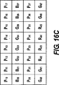
画素近傍の中心画素の1つがグリーン画素、例えば図16CにおけるG24である場合、下記予測子値が計算される。 If one of the central pixel of the pixel neighborhood is a G 24 in green pixels, for example, FIG. 16C, the following predictor values are computed.
画素近傍の中心画素の1つがグリーン画素、例えば図16DにおけるG24である場合、下記予測子値が計算される。 If one of the central pixel of the pixel neighborhood is a G 24 in green pixels, for example, FIG. 16D, the following predictor values are computed.
ブロック302(図3)によって計算される1つの分類子値集合がある。所与の近傍における中心画素の色は種々異なっていてよいが、分類子を計算するためには同じ式が用いられる。図16Aを参照すると、画素近傍の中心画素は、B24であり、そして下記分類子値が計算される。 There is one classifier value set calculated by block 302 (FIG. 3). Although the color of the center pixel in a given neighborhood can vary, the same formula is used to calculate the classifier. Referring to FIG. 16A, the central pixel near the pixel is B 24 and the following classifier value is calculated.
値tは、chorizontalがcslash、cvertical、又はcbackslashよりも小さいことの尤度を低減するが、しかし排除はしないために選択される閾値である。値tの典型的な値は、8ビット画素値データ範囲に関して20である。図16Bを参照すると、画素近傍の中心画素は、R24であり、そして下記分類子値が計算される。 The value t is a threshold chosen to reduce but not eliminate the likelihood that c horizontal is less than c slash , c vertical , or c backslash . A typical value for the value t is 20 for the 8-bit pixel value data range. Referring to FIG. 16B, the central pixel near the pixel is R 24 and the following classifier value is calculated.
値tは、chorizontalがcslash、cvertical、又はcbackslashよりも小さいことの尤度を低減するが、しかし排除はしないために選択される閾値である。値tの典型的な値は、8ビット画素値データ範囲に関して20である。図16Cを参照すると、画素近傍の中心画素は、G24であり、そして下記分類子値が計算される。 The value t is a threshold chosen to reduce but not eliminate the likelihood that c horizontal is less than c slash , c vertical , or c backslash . A typical value for the value t is 20 for the 8-bit pixel value data range. Referring to FIG. 16C, the central pixel of the pixel neighborhood is G 24, and the following classifier values are computed.
値tは、chorizontalがcslash、cvertical、又はcbackslashよりも小さいことの尤度を低減するが、しかし排除はしないために選択される閾値である。値tの典型的な値は、8ビット画素値データ範囲に関して20である。 The value t is a threshold chosen to reduce but not eliminate the likelihood that c horizontal is less than c slash , c vertical , or c backslash . A typical value for the value t is 20 for the 8-bit pixel value data range.
図3に戻ると、ブロック302において計算される分類子値は、計算方向決定ブロック304に渡される。ブロック304において、各分類子値が、活性閾値tactivityと比較される。tactivityの典型的な値は、8ビット画素値データ範囲に関して200である。全ての分類子値が活性閾値以上である場合、計算方向は、予測子値pcubicと連携する特殊事例となる。この第1の試験に失敗すると、最小値を有する分類子が決定される。この分類子と連携する方向は、ブロック304の出力になる。ブロック304の出力及びブロック300の出力は、高解像度パンクロマチック画素値計算ブロック306に渡される。ブロック306において、レッド、グリーン、又はブルー画素を中心とするそれぞれの画素近傍に対して、ブロック304で決定された計算方向に対応する予測子値は、補間されたパンクロマチック値になる。結果として生じる高解像度パンクロマチック・チャネルの一部が図17に示されている。図17において、下付き文字がない値は、元の既存のパンクロマチック値を表し、そして下付き文字を有する値は、補間されたパンクロマチック値を表す。加えて、図17は、図9に示された画素領域を生成するために、低解像度パンクロマチック画像形成ブロック206によって使用される画像領域である。下記式は、図9における画素値を生成するために、この好ましい態様において使用される。
Returning to FIG. 3, the classifier value calculated in
これらの式において、kは、出力値の所期画素値範囲を生成するためのスケール係数である。典型的には、kは、平均画素値を生成するためには8分の1である。 In these equations, k is a scale factor for generating the desired pixel value range of the output value. Typically k is 1/8 to produce an average pixel value.
図18は、高解像度色差形成ブロック210(図2)から形成された画素領域である。図18において、X1及びX5は、ブロック208(図2)によって形成された低解像度色差画像における既存の色差値を表す。下記式を用いて、ブロック210(図2)において補間された色差値X2、X3及びX4が計算される。 FIG. 18 shows a pixel region formed from the high-resolution color difference forming block 210 (FIG. 2). In FIG. 18, X 1 and X 5 represent existing color difference values in the low resolution color difference image formed by block 208 (FIG. 2). The interpolated color difference values X 2 , X 3, and X 4 are calculated using the following equation in block 210 (FIG. 2).
双2次線形補間のための標準的な実施と同様に、この演算は、各行における色差値量を3倍にするために各行に対して行われる。次いで、この計算は、各列における色差値量を3倍にするために各列に対して鉛直方向に繰り返される。ブロック210の出力は、高解像度フルカラー画像形成ブロック212に送られる。
Similar to the standard implementation for biquadratic linear interpolation, this operation is performed on each row to triple the amount of color difference values in each row. This calculation is then repeated vertically for each column to triple the amount of color difference values in each column. The output of
本発明の第3の別の態様をここで説明する。図2及び図3は、好ましい態様におけるものと同様である。図19は、RGBP CFA画像ブロック200(図2)全体にわたって反復された別の画素領域である。図19の顕著な特徴は、パンクロマチック画素の交互の単一の行及び単一の列が、隔離されたレッド、グリーン、及びブルー画素によって分離されていることである。 A third alternative aspect of the present invention will now be described. 2 and 3 are the same as in the preferred embodiment. FIG. 19 is another pixel region repeated throughout the RGBP CFA image block 200 (FIG. 2). The salient feature of FIG. 19 is that alternating single rows and single columns of panchromatic pixels are separated by isolated red, green and blue pixels.
図20は、図6に示された画素領域を生成するために、低解像度RGB CFA画像形成ブロック202(図2)によって使用される画素領域である。図6の画素値を生成するために、この別の態様において、下記式が用いられる。 FIG. 20 is a pixel area used by the low resolution RGB CFA imaging block 202 (FIG. 2) to generate the pixel area shown in FIG. In order to generate the pixel values of FIG. 6, in this alternative embodiment, the following equation is used:
これらの式において、kは、出力値の所期画素値範囲を生成するためのスケール係数である。kの典型的な値は、平均画素値を生成するためには4分の1、及び加算された画素値を生成するためには1である。なお、本発明の範囲内で、4つの画素値から1つの画素値を生成することは、サブサンプリングの形態である。 In these equations, k is a scale factor for generating the desired pixel value range of the output value. A typical value for k is a quarter to generate an average pixel value and 1 to generate an added pixel value. Note that generating one pixel value from four pixel values within the scope of the present invention is a form of sub-sampling.
図21は、画素近傍予測子計算ブロック300(図3)及び画素近傍分類子計算ブロック302(図3)の両方によって使用される別の画素領域を示す。中心画素X22はレッド、グリーン、又はブルー画素である。別の画素領域に関しては、下記予測子値が計算される。 FIG. 21 illustrates another pixel region used by both the pixel neighborhood predictor computation block 300 (FIG. 3) and the pixel neighborhood classifier computation block 302 (FIG. 3). The center pixel X 22 is a red, green, or blue pixel. For other pixel regions, the following predictor values are calculated:
同じ別の画素領域に関して、下記分類子が計算される。 The following classifier is calculated for the same different pixel region.
図3に戻ると、ブロック302において計算される分類子値は、計算方向決定ブロック304に渡される。ブロック304において、各分類子値が、活性閾値tactivityと比較される。tactivityの典型的な値は、8ビット画素値データ範囲に関して160である。全ての分類子値が活性閾値以下である場合、計算方向は、予測子値pflatと連携する特殊事例となる。この第1の試験に失敗すると、最小値を有する分類子が決定される。この分類子と連携する方向は、ブロック304の出力になる。ブロック304の出力及びブロック300の出力は、高解像度パンクロマチック画素値計算ブロック306に渡される。ブロック306において、レッド、グリーン、又はブルー画素を中心とするそれぞれの画素近傍に対して、ブロック304で決定された計算方向に対応する予測子値は、補間されたパンクロマチック値になる。結果として生じる高解像度パンクロマチック・チャネルの一部が図22に示されている。図22において、下付き文字がない値は、元の既存のパンクロマチック値を表し、そして下付き文字を有する値は、補間されたパンクロマチック値を表す。加えて、図22は、図9に示された画素領域を生成するために、低解像度パンクロマチック画像形成ブロック206(図2)によって使用される画像領域である。下記式は、図9における画素値を生成するために、この好ましい態様において使用される。
Returning to FIG. 3, the classifier value calculated in
これらの式において、kは、出力値の所期画素値範囲を生成するためのスケール係数である。典型的には、kは、平均画素値を生成するためには4分の1である。 In these equations, k is a scale factor for generating the desired pixel value range of the output value. Typically k is a quarter to produce an average pixel value.
図18は、高解像度色差形成ブロック210(図2)から形成された画素領域である。図18において、X1及びX5は、ブロック208(図2)によって形成された低解像度色差画像における既存の色差値を表す。下記式を用いて、ブロック210(図2)において補間された色差値X2、X3、及びX4が計算される。 FIG. 18 shows a pixel region formed from the high-resolution color difference forming block 210 (FIG. 2). In FIG. 18, X 1 and X 5 represent existing color difference values in the low resolution color difference image formed by block 208 (FIG. 2). The color difference values X 2 , X 3 , and X 4 interpolated in block 210 (FIG. 2) are calculated using the following equations:
双2次線形補間のための標準的な実施と同様に、この演算は、各行における色差値量を3倍にするために各行に対して行われる。次いで、この計算は、各列における色差値量を3倍にするために各列に対して鉛直方向に繰り返される。ブロック210の出力は、高解像度フルカラー画像形成ブロック212に送られる。
Similar to the standard implementation for biquadratic linear interpolation, this operation is performed on each row to triple the amount of color difference values in each row. This calculation is then repeated vertically for each column to triple the amount of color difference values in each column. The output of
本発明の好ましい態様に開示された補間アルゴリズムは、種々様々なユーザー状況及び環境において採用することができる。状況及び環境は、一例として、卸売業用デジタル写真仕上げ(例えば、フィルムの受け入れ、デジタル処理、プリントアウトのようなプロセス・ステップ又は段に関与する)、小売業用デジタル写真仕上げ(例えば、フィルムの受け入れ、デジタル処理、プリントアウト)、家庭内印刷(家庭内で走査されたフィルム又はデジタル画像、デジタル処理、プリントアウト)、デスクトップ・ソフトウェア(デジタルプリントをより良くするか、又はただこれらを変化させるだけのために、アルゴリズムをデジタルプリントに適用するソフトウェア)、デジタル・フルフィルメント(媒体からの、又はウェブを介したデジタル画像の受け入れ、デジタル処理、そして媒体上のデジタル形態の画像、又はウェブを介したデジタル形態の画像、又はハードコピー・プリント上に印刷された画像の納品を伴う)、キオスク(デジタル又は走査入力、デジタル処理、デジタル又は走査出力)、携帯デバイス(例えばPDA、又は処理ユニット、ディスプレイ・ユニット、又は処理指示を与えるためのユニットとして使用することができる携帯電話機)、及びワールド・ワイド・ウェブを介して提供されるサービスを含む。 The interpolation algorithm disclosed in the preferred embodiment of the present invention can be employed in a wide variety of user situations and environments. The situation and environment may include, for example, wholesale digital photofinishing (eg involved in process steps or stages such as film acceptance, digital processing, printout), retail digital photofinishing (eg film Acceptance, digital processing, printouts), home printing (films or digital images scanned in the home, digital processing, printouts), desktop software (better digital printing or just change them) Software that applies algorithms to digital prints), digital fulfillment (accepting digital images from the media or via the web, digital processing, and images in digital form on the media or via the web Images in digital form or Provide delivery of images printed on copy copies, kiosks (digital or scan input, digital processing, digital or scan output), portable devices (eg PDAs or processing units, display units, or processing instructions) Mobile phone that can be used as a unit for) and services provided via the World Wide Web.
それぞれの事例において、補間アルゴリズムは、独立していてよく、或いは、より大型のシステム手段の構成部分であってもよい。さらに、アルゴリズムを有するインターフェイス、例えば走査又は入力、デジタル処理、(必要な場合には)ユーザーに対する表示、(必要な場合には)ユーザー要求又は処理指示の入力、出力がそれぞれ、同じか又は異なるデバイス、及び物理的場所上で行われてよく、そしてデバイス及び場所の間の通信は、公的又は私的なネットワーク接続、又は媒体に基づく通信を介して行うことができる。本発明の前記開示内容と一致する場合には、アルゴリズム自体は、完全自動であってよく、ユーザー入力を有することができ(完全又は部分手動)、結果を受諾/拒絶するためのユーザー又は操作者の検閲を有することができ、或いはメタデータ(ユーザーによって供給するか、(例えばカメラ内の)測定デバイスによって供給するか、又はアルゴリズムによって決定することができるメタデータ)によって支援することができる。さらに、アルゴリズムは、種々のワークフロー・ユーザー・インターフェイス・スキームとインターフェイス接続することができる。 In each case, the interpolation algorithm may be independent or may be a component of a larger system means. In addition, interfaces with algorithms such as scanning or input, digital processing, display to the user (if necessary), input of user requests or processing instructions (if necessary), output, the same or different devices, respectively And communication between the device and the location can take place via public or private network connections or media based communication. In accordance with the above disclosure of the present invention, the algorithm itself may be fully automatic, may have user input (fully or partially manually), and the user or operator to accept / reject the results Or can be supported by metadata (metadata supplied by the user, supplied by a measurement device (eg in a camera) or determined by an algorithm). In addition, the algorithm can interface with various workflow user interface schemes.
本発明による本明細書中に開示された補間アルゴリズムは、種々のデータ検出・整理技術(例えば顔検出、眼検出、皮膚検出、フラッシュ検出)を利用する内部成分を有することができる。 The interpolation algorithm disclosed herein according to the present invention can have internal components that utilize various data detection and organization techniques (eg, face detection, eye detection, skin detection, flash detection).
110 コンピュータシステム
112 マイクロプロセッサをベースとするユニット
114 ディスプレイ
116 キーボード
118 マウス
120 ディスプレイ上のセレクタ
122 ディスク・ドライブ・ユニット
124 コンパクトディスク読み出し専用メモリ(CD−ROM)
126 フロッピー(登録商標)ディスク
127 ネットワーク接続
128 プリンタ
130 パーソナルコンピュータ・カード(PCカード)
132 PCカードリーダ
134 デジタルカメラ
136 カメラ・ドッキング・ポート
138 ケーブル接続
140 ワイヤレス接続
200 RGBP CFA画像
202 低解像度RGB CFA画像形成
204 高解像度パンクロマチック画像形成
206 低解像度パンクロマチック画像形成
208 低解像度色差形成
210 高解像度色差形成
212 高解像度フルカラー画像形成
214 高解像度フルカラー画像
216 低解像度色差画像補間
300 画素近傍予測子計算
302 画素近傍分類子計算
304 計算方向決定
306 高解像度パンクロマチック画素値計算
110
126
132
Claims (16)
(b) 該捕捉画像から、デジタル高解像度パンクロマチック画像、低解像度パンクロマチック画像、及び低解像度RGB CFA画像を提供すること;
(c) 低解像度色差画像を生成するために、該低解像度パンクロマチック画像及び該低解像度RGB CFA画像を使用すること;
(d) デジタル補間された低解像度色差画像を生成するために、該低解像度色差画像を使用すること;
(e) デジタル高解像度色差画像を生成するために、デジタル補間された低解像度色差画像を使用すること;そして
(f) 最終デジタル高解像度フルカラー画像を生成するために、該デジタル高解像度パンクロマチック画像及び該デジタル高解像度色差画像を使用すること
を含んで成る最終デジタルカラー画像を形成する方法。(A) The following sequence:
(B) providing a digital high resolution panchromatic image, a low resolution panchromatic image, and a low resolution RGB CFA image from the captured image;
(C) using the low resolution panchromatic image and the low resolution RGB CFA image to generate a low resolution color difference image;
(D) using the low resolution color difference image to generate a digitally interpolated low resolution color difference image;
(E) using a digitally interpolated low resolution color difference image to generate a digital high resolution color difference image; and (f) the digital high resolution panchromatic image to generate a final digital high resolution full color image. And a method of forming a final digital color image comprising using the digital high resolution color difference image.
Applications Claiming Priority (3)
| Application Number | Priority Date | Filing Date | Title |
|---|---|---|---|
| US11/341,206 | 2006-01-27 | ||
| US11/341,206 US7830430B2 (en) | 2005-07-28 | 2006-01-27 | Interpolation of panchromatic and color pixels |
| PCT/US2007/001113 WO2007089426A1 (en) | 2006-01-27 | 2007-01-17 | Interpolation of panchromatic and color pixels |
Publications (3)
| Publication Number | Publication Date |
|---|---|
| JP2009524989A JP2009524989A (en) | 2009-07-02 |
| JP2009524989A5 JP2009524989A5 (en) | 2011-03-17 |
| JP5123212B2 true JP5123212B2 (en) | 2013-01-23 |
Family
ID=38141171
Family Applications (1)
| Application Number | Title | Priority Date | Filing Date |
|---|---|---|---|
| JP2008552322A Active JP5123212B2 (en) | 2006-01-27 | 2007-01-17 | Interpolation of panchromatic and color pixels |
Country Status (6)
| Country | Link |
|---|---|
| US (1) | US7830430B2 (en) |
| EP (1) | EP1977613B1 (en) |
| JP (1) | JP5123212B2 (en) |
| KR (1) | KR101342806B1 (en) |
| CN (1) | CN101375610B (en) |
| WO (1) | WO2007089426A1 (en) |
Families Citing this family (53)
| Publication number | Priority date | Publication date | Assignee | Title |
|---|---|---|---|---|
| GB0503545D0 (en) * | 2005-02-21 | 2005-03-30 | E2V Tech Uk Ltd | Low light level colour camera |
| US8139130B2 (en) | 2005-07-28 | 2012-03-20 | Omnivision Technologies, Inc. | Image sensor with improved light sensitivity |
| US8274715B2 (en) | 2005-07-28 | 2012-09-25 | Omnivision Technologies, Inc. | Processing color and panchromatic pixels |
| US7916362B2 (en) | 2006-05-22 | 2011-03-29 | Eastman Kodak Company | Image sensor with improved light sensitivity |
| US8031258B2 (en) | 2006-10-04 | 2011-10-04 | Omnivision Technologies, Inc. | Providing multiple video signals from single sensor |
| US20080123997A1 (en) * | 2006-11-29 | 2008-05-29 | Adams James E | Providing a desired resolution color image |
| US7844127B2 (en) * | 2007-03-30 | 2010-11-30 | Eastman Kodak Company | Edge mapping using panchromatic pixels |
| US8594451B2 (en) * | 2007-03-30 | 2013-11-26 | Omnivision Technologies, Inc. | Edge mapping incorporating panchromatic pixels |
| US7889921B2 (en) * | 2007-05-23 | 2011-02-15 | Eastman Kodak Company | Noise reduced color image using panchromatic image |
| US8896712B2 (en) * | 2007-07-20 | 2014-11-25 | Omnivision Technologies, Inc. | Determining and correcting for imaging device motion during an exposure |
| US20090046182A1 (en) * | 2007-08-14 | 2009-02-19 | Adams Jr James E | Pixel aspect ratio correction using panchromatic pixels |
| US8452082B2 (en) * | 2007-09-27 | 2013-05-28 | Eastman Kodak Company | Pattern conversion for interpolation |
| US8411766B2 (en) * | 2008-04-09 | 2013-04-02 | Wi-Lan, Inc. | System and method for utilizing spectral resources in wireless communications |
| US20100149393A1 (en) * | 2008-05-22 | 2010-06-17 | Panavision Imaging, Llc | Increasing the resolution of color sub-pixel arrays |
| US8035711B2 (en) * | 2008-05-22 | 2011-10-11 | Panavision Imaging, Llc | Sub-pixel array optical sensor |
| US8350952B2 (en) * | 2008-06-04 | 2013-01-08 | Omnivision Technologies, Inc. | Image sensors with improved angle response |
| US7859033B2 (en) | 2008-07-09 | 2010-12-28 | Eastman Kodak Company | Wafer level processing for backside illuminated sensors |
| US7915067B2 (en) * | 2008-07-09 | 2011-03-29 | Eastman Kodak Company | Backside illuminated image sensor with reduced dark current |
| US8164669B2 (en) * | 2008-12-19 | 2012-04-24 | Truesense Imaging, Inc. | Charge-coupled device image sensor with efficient binning of same-color pixels |
| US8224082B2 (en) * | 2009-03-10 | 2012-07-17 | Omnivision Technologies, Inc. | CFA image with synthetic panchromatic image |
| US8068153B2 (en) | 2009-03-27 | 2011-11-29 | Omnivision Technologies, Inc. | Producing full-color image using CFA image |
| US8045024B2 (en) * | 2009-04-15 | 2011-10-25 | Omnivision Technologies, Inc. | Producing full-color image with reduced motion blur |
| US8203633B2 (en) * | 2009-05-27 | 2012-06-19 | Omnivision Technologies, Inc. | Four-channel color filter array pattern |
| JP5169994B2 (en) * | 2009-05-27 | 2013-03-27 | ソニー株式会社 | Image processing apparatus, imaging apparatus, and image processing method |
| US8237831B2 (en) * | 2009-05-28 | 2012-08-07 | Omnivision Technologies, Inc. | Four-channel color filter array interpolation |
| US8125546B2 (en) * | 2009-06-05 | 2012-02-28 | Omnivision Technologies, Inc. | Color filter array pattern having four-channels |
| US8253832B2 (en) * | 2009-06-09 | 2012-08-28 | Omnivision Technologies, Inc. | Interpolation for four-channel color filter array |
| JP5326943B2 (en) * | 2009-08-31 | 2013-10-30 | ソニー株式会社 | Image processing apparatus, image processing method, and program |
| JP5454075B2 (en) | 2009-10-20 | 2014-03-26 | ソニー株式会社 | Image processing apparatus, image processing method, and program |
| US20110205384A1 (en) * | 2010-02-24 | 2011-08-25 | Panavision Imaging, Llc | Variable active image area image sensor |
| JP5724185B2 (en) | 2010-03-04 | 2015-05-27 | ソニー株式会社 | Image processing apparatus, image processing method, and program |
| KR101671927B1 (en) | 2010-07-21 | 2016-11-04 | 삼성전자주식회사 | Apparatus and method for processing image |
| US9936109B2 (en) * | 2010-10-22 | 2018-04-03 | University Of New Brunswick | Method and system for fusing images |
| US9930316B2 (en) | 2013-08-16 | 2018-03-27 | University Of New Brunswick | Camera imaging systems and methods |
| US20120236173A1 (en) | 2011-03-17 | 2012-09-20 | Telek Michael J | Digital camera user interface which adapts to environmental conditions |
| DE202012013411U1 (en) | 2011-04-25 | 2016-11-15 | Terra Bella Technologies Inc. | Systems for overhead image and video display |
| EP2677732B1 (en) * | 2012-06-22 | 2019-08-28 | Nokia Technologies Oy | Method, apparatus and computer program product for capturing video content |
| US10230925B2 (en) | 2014-06-13 | 2019-03-12 | Urthecast Corp. | Systems and methods for processing and providing terrestrial and/or space-based earth observation video |
| US9225889B1 (en) | 2014-08-18 | 2015-12-29 | Entropix, Inc. | Photographic image acquisition device and method |
| US10871561B2 (en) | 2015-03-25 | 2020-12-22 | Urthecast Corp. | Apparatus and methods for synthetic aperture radar with digital beamforming |
| JP6622481B2 (en) * | 2015-04-15 | 2019-12-18 | キヤノン株式会社 | Imaging apparatus, imaging system, signal processing method for imaging apparatus, and signal processing method |
| US10615513B2 (en) | 2015-06-16 | 2020-04-07 | Urthecast Corp | Efficient planar phased array antenna assembly |
| EP3380864A4 (en) | 2015-11-25 | 2019-07-03 | Urthecast Corp. | Synthetic aperture radar imaging apparatus and methods |
| WO2017131618A1 (en) * | 2016-01-25 | 2017-08-03 | Hewlett-Packard Development Company, L.P. | Interpolating pixel values |
| CN105979233B (en) * | 2016-06-30 | 2018-10-19 | 北京奇艺世纪科技有限公司 | Demosaicing methods, image processor and imaging sensor |
| US11378682B2 (en) | 2017-05-23 | 2022-07-05 | Spacealpha Insights Corp. | Synthetic aperture radar imaging apparatus and methods for moving targets |
| CA3064735C (en) | 2017-05-23 | 2022-06-21 | Urthecast Corp. | Synthetic aperture radar imaging apparatus and methods |
| US11525910B2 (en) | 2017-11-22 | 2022-12-13 | Spacealpha Insights Corp. | Synthetic aperture radar apparatus and methods |
| JP7349806B2 (en) * | 2018-03-28 | 2023-09-25 | ブラックマジック デザイン ピーティーワイ リミテッド | Image processing method and filter array |
| CN114422766A (en) * | 2018-08-03 | 2022-04-29 | 杭州海康威视数字技术股份有限公司 | Image acquisition equipment |
| US10863128B2 (en) * | 2019-01-15 | 2020-12-08 | Bae Systems Information And Electronic Systems Integration Inc. | RCCC to monochrome interpolator |
| JP2023010159A (en) * | 2021-07-09 | 2023-01-20 | 株式会社ソシオネクスト | Image processing device and image processing method |
| CN114466170B (en) * | 2021-08-27 | 2023-10-31 | 锐芯微电子股份有限公司 | Image processing method and system |
Family Cites Families (26)
| Publication number | Priority date | Publication date | Assignee | Title |
|---|---|---|---|---|
| US472299A (en) * | 1892-04-05 | Bean pickerand sorter | ||
| US1035729A (en) * | 1911-08-03 | 1912-08-13 | Stanley C Peters | Composition of matter. |
| US1411471A (en) * | 1921-10-21 | 1922-04-04 | Ebenezer H Booth | Pipe wrench |
| JPH0488784A (en) * | 1990-07-31 | 1992-03-23 | Canon Inc | Color image pickup element and signal processing system |
| US5323233A (en) * | 1990-07-31 | 1994-06-21 | Canon Kabushiki Kaisha | Image signal processing apparatus having a color filter with offset luminance filter elements |
| US5374956A (en) * | 1992-05-29 | 1994-12-20 | Eastman Kodak Company | Electronic imaging apparatus with dithered color filter array |
| US5629734A (en) * | 1995-03-17 | 1997-05-13 | Eastman Kodak Company | Adaptive color plan interpolation in single sensor color electronic camera |
| US5506619A (en) * | 1995-03-17 | 1996-04-09 | Eastman Kodak Company | Adaptive color plan interpolation in single sensor color electronic camera |
| US5596367A (en) * | 1996-02-23 | 1997-01-21 | Eastman Kodak Company | Averaging green values for green photosites in electronic cameras |
| JP4377976B2 (en) * | 1997-12-26 | 2009-12-02 | キヤノン株式会社 | Color imaging apparatus, image signal reading method, image processing apparatus, image processing system, and storage medium |
| KR100398564B1 (en) * | 1998-05-08 | 2003-09-19 | 마츠시타 덴끼 산교 가부시키가이샤 | Solid-state color imager |
| US6529239B1 (en) * | 1998-06-01 | 2003-03-04 | Fairchild Imaging, Inc. | Image sensor with stripes of cyan filter material perpendicular to stripes of yellow filter material |
| US6697107B1 (en) * | 1998-07-09 | 2004-02-24 | Eastman Kodak Company | Smoothing a digital color image using luminance values |
| JP3784602B2 (en) | 1999-03-08 | 2006-06-14 | シャープ株式会社 | Image reading method and image reading system |
| US6714243B1 (en) * | 1999-03-22 | 2004-03-30 | Biomorphic Vlsi, Inc. | Color filter pattern |
| JP4626007B2 (en) * | 1999-06-14 | 2011-02-02 | 株式会社ニコン | Image processing method, machine-readable recording medium storing image processing program, and image processing apparatus |
| US6757012B1 (en) * | 2000-01-13 | 2004-06-29 | Biomorphic Vlsi, Inc. | Color selection for sparse color image reconstruction |
| CA2355021C (en) * | 2000-08-29 | 2004-11-02 | Hoya Corporation | Optical element having antireflection film |
| JP4517493B2 (en) * | 2000-10-18 | 2010-08-04 | ソニー株式会社 | Solid-state imaging device and signal processing method thereof |
| US7088392B2 (en) * | 2001-08-27 | 2006-08-08 | Ramakrishna Kakarala | Digital image system and method for implementing an adaptive demosaicing method |
| US7199122B2 (en) * | 2001-10-02 | 2007-04-03 | Fox Chase Cancer Center | Methods for inhibiting angiogenesis |
| US7012643B2 (en) | 2002-05-08 | 2006-03-14 | Ball Aerospace & Technologies Corp. | One chip, low light level color camera |
| US7084906B2 (en) | 2002-10-15 | 2006-08-01 | Eastman Kodak Company | Reducing computation time in removing color aliasing artifacts from color digital images |
| JP2004304706A (en) * | 2003-04-01 | 2004-10-28 | Fuji Photo Film Co Ltd | Solid-state imaging apparatus and interpolation processing method thereof |
| KR100699831B1 (en) * | 2004-12-16 | 2007-03-27 | 삼성전자주식회사 | Method and apparatus for interpolating Bayer-pattern color signals |
| US8139130B2 (en) | 2005-07-28 | 2012-03-20 | Omnivision Technologies, Inc. | Image sensor with improved light sensitivity |
-
2006
- 2006-01-27 US US11/341,206 patent/US7830430B2/en active Active
-
2007
- 2007-01-17 JP JP2008552322A patent/JP5123212B2/en active Active
- 2007-01-17 CN CN2007800034839A patent/CN101375610B/en active Active
- 2007-01-17 WO PCT/US2007/001113 patent/WO2007089426A1/en active Application Filing
- 2007-01-17 EP EP07716670.0A patent/EP1977613B1/en active Active
-
2008
- 2008-07-25 KR KR1020087018404A patent/KR101342806B1/en active IP Right Grant
Also Published As
| Publication number | Publication date |
|---|---|
| EP1977613A1 (en) | 2008-10-08 |
| WO2007089426A1 (en) | 2007-08-09 |
| KR101342806B1 (en) | 2013-12-17 |
| US20070024934A1 (en) | 2007-02-01 |
| CN101375610A (en) | 2009-02-25 |
| US7830430B2 (en) | 2010-11-09 |
| JP2009524989A (en) | 2009-07-02 |
| CN101375610B (en) | 2011-09-21 |
| KR20080096522A (en) | 2008-10-30 |
| EP1977613B1 (en) | 2015-10-07 |
Similar Documents
| Publication | Publication Date | Title |
|---|---|---|
| JP5123212B2 (en) | Interpolation of panchromatic and color pixels | |
| JP5260635B2 (en) | Noise-reduced color image using panchromatic image | |
| US20080123997A1 (en) | Providing a desired resolution color image | |
| JP5395053B2 (en) | Edge mapping using panchromatic pixels | |
| US7876956B2 (en) | Noise reduction of panchromatic and color image | |
| EP1395041B1 (en) | Colour correction of images | |
| TWI430202B (en) | Method of sharpening using panchromatic pixels | |
| JP5291084B2 (en) | Edge mapping incorporating panchromatic pixels | |
| US7652717B2 (en) | White balance correction in digital camera images | |
| JP2010537228A (en) | Pixel aspect ratio correction using panchromatic pixels | |
| JPH08298670A (en) | Adaptive color interpolation single sensor color electronic camera | |
| US20060152596A1 (en) | Noise cleaning sparsely populated color digital images | |
| US20050140804A1 (en) | Extended dynamic range image sensor capture using an array of fast and slow pixels |
Legal Events
| Date | Code | Title | Description |
|---|---|---|---|
| A521 | Request for written amendment filed |
Free format text: JAPANESE INTERMEDIATE CODE: A523 Effective date: 20100113 |
|
| A621 | Written request for application examination |
Free format text: JAPANESE INTERMEDIATE CODE: A621 Effective date: 20100113 |
|
| A521 | Request for written amendment filed |
Free format text: JAPANESE INTERMEDIATE CODE: A523 Effective date: 20110316 |
|
| A711 | Notification of change in applicant |
Free format text: JAPANESE INTERMEDIATE CODE: A711 Effective date: 20110608 |
|
| A977 | Report on retrieval |
Free format text: JAPANESE INTERMEDIATE CODE: A971007 Effective date: 20110707 |
|
| A131 | Notification of reasons for refusal |
Free format text: JAPANESE INTERMEDIATE CODE: A131 Effective date: 20110719 |
|
| A601 | Written request for extension of time |
Free format text: JAPANESE INTERMEDIATE CODE: A601 Effective date: 20111018 |
|
| A602 | Written permission of extension of time |
Free format text: JAPANESE INTERMEDIATE CODE: A602 Effective date: 20111025 |
|
| A521 | Request for written amendment filed |
Free format text: JAPANESE INTERMEDIATE CODE: A523 Effective date: 20120119 |
|
| A131 | Notification of reasons for refusal |
Free format text: JAPANESE INTERMEDIATE CODE: A131 Effective date: 20120529 |
|
| A521 | Request for written amendment filed |
Free format text: JAPANESE INTERMEDIATE CODE: A523 Effective date: 20120829 |
|
| TRDD | Decision of grant or rejection written | ||
| A01 | Written decision to grant a patent or to grant a registration (utility model) |
Free format text: JAPANESE INTERMEDIATE CODE: A01 Effective date: 20120925 |
|
| A01 | Written decision to grant a patent or to grant a registration (utility model) |
Free format text: JAPANESE INTERMEDIATE CODE: A01 |
|
| A61 | First payment of annual fees (during grant procedure) |
Free format text: JAPANESE INTERMEDIATE CODE: A61 Effective date: 20121025 |
|
| FPAY | Renewal fee payment (event date is renewal date of database) |
Free format text: PAYMENT UNTIL: 20151102 Year of fee payment: 3 |
|
| R150 | Certificate of patent or registration of utility model |
Free format text: JAPANESE INTERMEDIATE CODE: R150 Ref document number: 5123212 Country of ref document: JP Free format text: JAPANESE INTERMEDIATE CODE: R150 |
|
| R250 | Receipt of annual fees |
Free format text: JAPANESE INTERMEDIATE CODE: R250 |
|
| R250 | Receipt of annual fees |
Free format text: JAPANESE INTERMEDIATE CODE: R250 |
|
| R250 | Receipt of annual fees |
Free format text: JAPANESE INTERMEDIATE CODE: R250 |
|
| R250 | Receipt of annual fees |
Free format text: JAPANESE INTERMEDIATE CODE: R250 |
|
| R250 | Receipt of annual fees |
Free format text: JAPANESE INTERMEDIATE CODE: R250 |
|
| R250 | Receipt of annual fees |
Free format text: JAPANESE INTERMEDIATE CODE: R250 |
|
| R250 | Receipt of annual fees |
Free format text: JAPANESE INTERMEDIATE CODE: R250 |
|
| R250 | Receipt of annual fees |
Free format text: JAPANESE INTERMEDIATE CODE: R250 |
|
| R250 | Receipt of annual fees |
Free format text: JAPANESE INTERMEDIATE CODE: R250 |