JP5122918B2 - Device to reduce tension on elastic feed - Google Patents
Device to reduce tension on elastic feed Download PDFInfo
- Publication number
- JP5122918B2 JP5122918B2 JP2007287964A JP2007287964A JP5122918B2 JP 5122918 B2 JP5122918 B2 JP 5122918B2 JP 2007287964 A JP2007287964 A JP 2007287964A JP 2007287964 A JP2007287964 A JP 2007287964A JP 5122918 B2 JP5122918 B2 JP 5122918B2
- Authority
- JP
- Japan
- Prior art keywords
- strip
- support frame
- supply strip
- tension
- hydraulic
- Prior art date
- Legal status (The legal status is an assumption and is not a legal conclusion. Google has not performed a legal analysis and makes no representation as to the accuracy of the status listed.)
- Expired - Fee Related
Links
Images


Classifications
-
- B—PERFORMING OPERATIONS; TRANSPORTING
- B65—CONVEYING; PACKING; STORING; HANDLING THIN OR FILAMENTARY MATERIAL
- B65H—HANDLING THIN OR FILAMENTARY MATERIAL, e.g. SHEETS, WEBS, CABLES
- B65H23/00—Registering, tensioning, smoothing or guiding webs
- B65H23/04—Registering, tensioning, smoothing or guiding webs longitudinally
- B65H23/18—Registering, tensioning, smoothing or guiding webs longitudinally by controlling or regulating the web-advancing mechanism, e.g. mechanism acting on the running web
- B65H23/188—Registering, tensioning, smoothing or guiding webs longitudinally by controlling or regulating the web-advancing mechanism, e.g. mechanism acting on the running web in connection with running-web
- B65H23/1888—Registering, tensioning, smoothing or guiding webs longitudinally by controlling or regulating the web-advancing mechanism, e.g. mechanism acting on the running web in connection with running-web and controlling web tension
-
- B—PERFORMING OPERATIONS; TRANSPORTING
- B29—WORKING OF PLASTICS; WORKING OF SUBSTANCES IN A PLASTIC STATE IN GENERAL
- B29C—SHAPING OR JOINING OF PLASTICS; SHAPING OF MATERIAL IN A PLASTIC STATE, NOT OTHERWISE PROVIDED FOR; AFTER-TREATMENT OF THE SHAPED PRODUCTS, e.g. REPAIRING
- B29C48/00—Extrusion moulding, i.e. expressing the moulding material through a die or nozzle which imparts the desired form; Apparatus therefor
- B29C48/03—Extrusion moulding, i.e. expressing the moulding material through a die or nozzle which imparts the desired form; Apparatus therefor characterised by the shape of the extruded material at extrusion
- B29C48/07—Flat, e.g. panels
-
- B—PERFORMING OPERATIONS; TRANSPORTING
- B29—WORKING OF PLASTICS; WORKING OF SUBSTANCES IN A PLASTIC STATE IN GENERAL
- B29C—SHAPING OR JOINING OF PLASTICS; SHAPING OF MATERIAL IN A PLASTIC STATE, NOT OTHERWISE PROVIDED FOR; AFTER-TREATMENT OF THE SHAPED PRODUCTS, e.g. REPAIRING
- B29C48/00—Extrusion moulding, i.e. expressing the moulding material through a die or nozzle which imparts the desired form; Apparatus therefor
- B29C48/25—Component parts, details or accessories; Auxiliary operations
- B29C48/285—Feeding the extrusion material to the extruder
- B29C48/288—Feeding the extrusion material to the extruder in solid form, e.g. powder or granules
- B29C48/2888—Feeding the extrusion material to the extruder in solid form, e.g. powder or granules in band or in strip form, e.g. rubber strips
-
- B—PERFORMING OPERATIONS; TRANSPORTING
- B29—WORKING OF PLASTICS; WORKING OF SUBSTANCES IN A PLASTIC STATE IN GENERAL
- B29C—SHAPING OR JOINING OF PLASTICS; SHAPING OF MATERIAL IN A PLASTIC STATE, NOT OTHERWISE PROVIDED FOR; AFTER-TREATMENT OF THE SHAPED PRODUCTS, e.g. REPAIRING
- B29C48/00—Extrusion moulding, i.e. expressing the moulding material through a die or nozzle which imparts the desired form; Apparatus therefor
- B29C48/25—Component parts, details or accessories; Auxiliary operations
- B29C48/36—Means for plasticising or homogenising the moulding material or forcing it through the nozzle or die
- B29C48/365—Means for plasticising or homogenising the moulding material or forcing it through the nozzle or die using pumps, e.g. piston pumps
- B29C48/37—Gear pumps
-
- B—PERFORMING OPERATIONS; TRANSPORTING
- B65—CONVEYING; PACKING; STORING; HANDLING THIN OR FILAMENTARY MATERIAL
- B65H—HANDLING THIN OR FILAMENTARY MATERIAL, e.g. SHEETS, WEBS, CABLES
- B65H20/00—Advancing webs
- B65H20/02—Advancing webs by friction roller
- B65H20/04—Advancing webs by friction roller to effect step-by-step advancement of web
-
- B—PERFORMING OPERATIONS; TRANSPORTING
- B65—CONVEYING; PACKING; STORING; HANDLING THIN OR FILAMENTARY MATERIAL
- B65H—HANDLING THIN OR FILAMENTARY MATERIAL, e.g. SHEETS, WEBS, CABLES
- B65H20/00—Advancing webs
- B65H20/24—Advancing webs by looping or like devices
-
- B—PERFORMING OPERATIONS; TRANSPORTING
- B29—WORKING OF PLASTICS; WORKING OF SUBSTANCES IN A PLASTIC STATE IN GENERAL
- B29K—INDEXING SCHEME ASSOCIATED WITH SUBCLASSES B29B, B29C OR B29D, RELATING TO MOULDING MATERIALS OR TO MATERIALS FOR MOULDS, REINFORCEMENTS, FILLERS OR PREFORMED PARTS, e.g. INSERTS
- B29K2021/00—Use of unspecified rubbers as moulding material
-
- B—PERFORMING OPERATIONS; TRANSPORTING
- B65—CONVEYING; PACKING; STORING; HANDLING THIN OR FILAMENTARY MATERIAL
- B65H—HANDLING THIN OR FILAMENTARY MATERIAL, e.g. SHEETS, WEBS, CABLES
- B65H2801/00—Application field
- B65H2801/93—Tyres
Landscapes
- Engineering & Computer Science (AREA)
- Mechanical Engineering (AREA)
- Tyre Moulding (AREA)
- Extrusion Moulding Of Plastics Or The Like (AREA)
- Processing And Handling Of Plastics And Other Materials For Molding In General (AREA)
- Electroluminescent Light Sources (AREA)
Description
本発明は、供給ストリップの張力を軽減することに関し、特に、押出機への弾性供給ストリップの張力を軽減することに関する The present invention relates to reducing the tension of a supply strip, and in particular to reducing the tension of an elastic supply strip to an extruder.
ギアポンプ押出機は、ゴム構成部材を押し出し成形するためにタイヤ産業界で使用されている。通常、大形のゴム供給ストリップが押出機のフィードボックス(a feed box)に送られる。場合によっては、ギアポンプ押出機は間欠的に動作することができる。 Gear pump extruders are used in the tire industry to extrude rubber components. Usually, a large rubber feed strip is sent to the feed box of the extruder. In some cases, the gear pump extruder can operate intermittently.
押出機が停止すると、材料の供給ストリップに張力が働く。張力が大きすぎると、押出機のフィードボックス内の高温のゴム/金属のために供給ストリップが破断されることがある。ストリップが破断されると、生産に問題が生じるかまたは押出機が停止するか、あるいは場合によってはフィードボックスに供給ストリップが再供給されるまで押出機/ギアポンプの出力が誤ったものになる恐れがある。したがって、前述の欠点のない改良された供給システムを有することが望ましい。 When the extruder is stopped, tension is applied to the feed strip of material. If the tension is too high, the feed strip may break due to the hot rubber / metal in the extruder feed box. If the strip breaks, it can cause production problems or the extruder stops, or in some cases the output of the extruder / gear pump can be incorrect until the feed strip is re-fed to the feed box. is there. Therefore, it would be desirable to have an improved delivery system that does not have the aforementioned disadvantages.
本発明は、第1の態様では、押出機システムの弾性供給ストリップに対する張力を軽減する方法であって、供給ストリップに接触する装置を設けることと、供給ストリップがその前進運動を停止したときに装置によって供給ストリップを前方に押し出すこととを含む方法を提供する。装置は、一方向軸受を有するローラまたは支持板を有する。 The present invention, in a first aspect, is a method of reducing tension on an elastic supply strip of an extruder system, the apparatus comprising a device contacting the supply strip and the device when the supply strip stops its forward movement Pushing the feed strip forward. The device has a roller or support plate with unidirectional bearings.
供給ストリップに接触する張力軽減装置は、1つまたは2つ以上の支持脚を有する支持フレームを含み、支持フレームは第1の位置から第1の位置とは異なる第2の位置へ移動することができ、張力軽減装置は、供給ストリップに接触し、供給ストリップをその移動方向と同じ方向に押し出し、それによって供給ストリップの張力を軽減する供給ストリップ接触装置をさらに有する。 The strain relief device that contacts the supply strip includes a support frame having one or more support legs, the support frame being capable of moving from the first position to a second position different from the first position. The tension relief device can further comprise a supply strip contact device that contacts the supply strip and pushes the supply strip in the same direction of movement, thereby reducing the tension of the supply strip.
本発明によれば、ストリップの張力が該ストリップが破断されるのを防止するのに十分な程度に軽減される。 According to the present invention, the tension of the strip is reduced to a degree sufficient to prevent the strip from breaking.
本発明について、一例として添付の図面を参照して説明する。 The present invention will now be described by way of example with reference to the accompanying drawings.
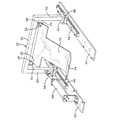
供給ストリップ張力軽減装置10が図1に示されている。供給ストリップ張力軽減装置10は、エラストマまたはゴムの供給ストリップを必要とする押出機または他の装置と一緒に使用するのに適している。供給ストリップ張力軽減装置10は、後述のようにエラストマの供給ストリップを前方に押し出すことによってエラストマの供給ストリップの張力を解放するように働く。
A supply
供給ストリップ張力軽減装置10は、概ねコンベアシステム22の走行方向を横切るかまたはコンベアシステムの走行方向に垂直に向けられた支持フレーム20を有している。コンベアシステムは通常、並列関係に取り付けられ、弾性ストリップを押出機または他の装置に搬送するコンベアシステムを形成する複数のローラ24を有している。ローラの代わりにコンベアベルト(不図示)を使用してもよい。
The supply strip
支持フレーム20は、支持脚50、52を接合する上部補強棒21を含んでいる。支持脚50、52は、コンベアシステムの互いに向かい合うサイドレール25上に取り付けられている。上部補強棒21は、2つの支持レール26、27の端部をピン28によってピボット運動可能に連結する互いに向かい合う2つのフランジ55をさらに含んでいる。
The
支持レール26、27間に1つまたは2つ以上の横棒30、32が取り付けられている。下方の横棒30の中央には、横棒30に回転可能に取り付けられたローラ40が設けられている。ローラ40は、互いに向かい合う溝44を有してよい外側駆動面42を有している。ローラ40の内側に、ローラ40が一方向のみに回転するのを可能にする一方向軸受(不図示)が設けられている。ローラ40は、供給ストリップと一緒にのみ回転することができ、すなわち、供給ストリップの移動方向にのみ回転することができる。ローラ40は、押出機の動作中に供給ストリップに接触し、供給ストリップと一緒に回転することができる。
One or more
フレーム側の支持脚50、52は、スライド可能なブロック60上に取り付けられたフランジ付き端部54を有している。ブロック60は、レール64をスライド可能に受け入れる内側溝62をさらに有している。したがって、支持フレーム20全体は、レール64上を前後にスライドすることができる。支持フレーム20は、引き込み可能なアーム68を有する空気圧、油圧または水圧機構(以下「油圧機構」と総称する。)66にさらに連結されている。引き込み可能なアーム68は支持脚52の下部に連結されている。したがって、油圧機構は、アーム68を伸ばしかつ引き込み、支持フレーム20をレール64上で前後にスライドさせる。図2は、引き込み位置における支持フレーム組立体を示している。さらに図2に示されているように、油圧アーム68は、支持フレーム20が完全引き込み位置に来たときに完全に伸ばされる。図1は、支持フレーム組立体を完全前方位置まで移動させた後の、引き込み位置における油圧アーム68を示している。油圧アーム68の動作は、押出機ギアポンプが空転するかまたはオフにされたときに引き込み位置に引き込むように油圧アーム68を制御するシステムPLCコントローラ(不図示)によって制御することができる。油圧アーム68が引き込むと、支持フレーム20がレール64上を前方に滑り(供給ストリップと同じ走行方向)、ローラ40が供給ストリップを前方に押し出し、それによって供給ストリップの張力を軽減する。ストリップの張力は、ストリップが破断されるのを防止するのに十分な程度に軽減される。システムコントローラは次いで、油圧アーム68が完全に伸びるように制御し、供給ストリップ張力軽減装置10を開始または引き込み位置に戻す。
The frame-
図3は、供給ストリップ張力軽減装置の他の実施形態を示している。ローラ40および支持レール26、27が支持板70で置き換えられていることを除いてすべての構成部材は上述のとおりである。支持板70は、ピン28を介して支持棒21のフランジ55にピボット運動可能に連結された管状の端部72を有している。支持板70は、供給ストリップに接触するように位置する傾斜した端部74を有している。支持板70は、任意の所望の形状を有してよく、図示のようにT字形に限らない。端部74は、供給ストリップに沿って重なる。押出機ギアポンプが空転するかまたはオフにされると、油圧アーム68が引き込み、支持フレーム20をレール64上を前方に(供給ストリップと同じ方向に)スライドさせ、支持板70がストリップに接触し、ストリップを前方に押し出し、それによって供給ストリップの張力を軽減する。ストリップの張力は、ストリップが破断されるのを防止するのに十分な程度に軽減される。システムコントローラは次いで、油圧アーム68が完全に伸びるように制御し、供給ストリップ張力軽減装置10を開始または引き込み位置に戻す。
FIG. 3 illustrates another embodiment of a supply strip tension relief device. All components are as described above except that the
本明細書に与えられた本発明の説明を考慮して本発明の変形が可能である。本発明を例示するためにある代表的な実施形態および詳細を示したが、当業者には、本発明の範囲から逸脱せずに実施形態に様々な変更および修正を施せることが明らかであろう。したがって、添付の特許請求の範囲によって定義される本発明の対象となる全範囲内の変更を前述の特定の実施形態に施せることを理解されたい。 Variations of the present invention are possible in light of the description of the invention provided herein. While exemplary embodiments and details have been shown to illustrate the present invention, it will be apparent to those skilled in the art that various changes and modifications can be made to the embodiments without departing from the scope of the invention. . It is therefore to be understood that changes may be made in the particular embodiments described above that fall within the full scope of the invention as defined by the appended claims.
10 供給ストリップ張力軽減装置
20 支持フレーム
22 コンベアシステム
24 ローラ
25 サイドレール
26、27 支持レール
28 ピン
30、32 横棒
40 ローラ
42 外側駆動面
44 溝
50、52 支持脚
55 フランジ
60 ブロック
64 レール
66 空気圧、油圧または水圧機構
68 アーム
70 支持板
72 管状の端部
74 端部
DESCRIPTION OF
Claims (9)
油圧または水圧機構に連結された支持フレームとを有し、前記支持フレームはサイドレールにスライド可能に取り付けられ、前記油圧または水圧機構は前記支持フレームに連結された引き込み可能なアームを有する、前記供給ストリップに接触する装置を設けるステップと、
前記供給ストリップがその前進運動を停止したときに前記装置によって前記供給ストリップを前方に押し出すステップと、を含む方法。 A method of reducing tension on an elastic feed strip of an extruder system comprising:
A support frame coupled to a hydraulic or hydraulic mechanism, the support frame slidably mounted on a side rail, and the hydraulic or hydraulic mechanism having a retractable arm coupled to the support frame. Providing a device for contacting the strip;
Pushing the supply strip forward by the device when the supply strip stops its forward movement.
一方向軸受を有するローラと、油圧または水圧機構に連結された支持フレームとを有し、前記支持フレームはサイドレールにスライド可能に取り付けられ、前記油圧または水圧機構は前記支持フレームに連結された引き込み可能なアームを有する、前記供給ストリップに接触する装置を設けるステップと、
前記供給ストリップの張力を監視するステップと、
前記張力があるレベルを超えたときに前記装置によって前記供給ストリップを前方に押し出すステップと、を含む方法。 A method of reducing tension on an elastic feed strip of an extruder system comprising:
A roller having a one-way bearing; and a support frame coupled to a hydraulic or hydraulic mechanism, the support frame being slidably attached to a side rail, and the hydraulic or hydraulic mechanism being retracted coupled to the support frame Providing a device in contact with the supply strip having a possible arm ;
Monitoring the tension of the supply strip;
Method comprising the steps of extruding the feed strip forward by the device when it exceeds a certain level said tensile force.
The tension relief device of claim 7 , wherein the supply strip contact device comprises a support plate.
Applications Claiming Priority (2)
| Application Number | Priority Date | Filing Date | Title |
|---|---|---|---|
| US11/599,773 | 2006-11-15 | ||
| US11/599,773 US7604148B2 (en) | 2006-11-15 | 2006-11-15 | Device for reducing the tension on an elastomeric feed |
Publications (2)
| Publication Number | Publication Date |
|---|---|
| JP2008120082A JP2008120082A (en) | 2008-05-29 |
| JP5122918B2 true JP5122918B2 (en) | 2013-01-16 |
Family
ID=39092816
Family Applications (1)
| Application Number | Title | Priority Date | Filing Date |
|---|---|---|---|
| JP2007287964A Expired - Fee Related JP5122918B2 (en) | 2006-11-15 | 2007-11-06 | Device to reduce tension on elastic feed |
Country Status (5)
| Country | Link |
|---|---|
| US (1) | US7604148B2 (en) |
| EP (1) | EP1923198A1 (en) |
| JP (1) | JP5122918B2 (en) |
| CN (1) | CN101181819B (en) |
| BR (1) | BRPI0704067A (en) |
Families Citing this family (6)
| Publication number | Priority date | Publication date | Assignee | Title |
|---|---|---|---|---|
| CN102962908B (en) * | 2012-11-28 | 2015-09-30 | 烟台鑫海矿山机械有限公司 | A kind of object transfer device |
| CN105606625B (en) * | 2016-02-03 | 2018-06-26 | 宁波韵升智能技术有限公司 | A kind of appearance defect detection device of thin slice band-type product |
| DE102016115049B3 (en) * | 2016-08-12 | 2018-02-15 | Troester Gmbh & Co. Kg | Device for feeding an extruder |
| CN109940915A (en) * | 2019-04-11 | 2019-06-28 | 湖北玲珑轮胎有限公司 | The material of Telescopic swing conveys laminating apparatus |
| CA3079153C (en) * | 2019-06-25 | 2022-08-02 | Omachron Intellectual Property Inc. | Puller apparatus with movable mounting arm |
| KR102123797B1 (en) * | 2019-10-10 | 2020-06-17 | 주식회사 연우케미칼 | Buoy manufacturing equipment |
Family Cites Families (11)
| Publication number | Priority date | Publication date | Assignee | Title |
|---|---|---|---|---|
| US3841818A (en) | 1973-01-24 | 1974-10-15 | Johnson Rubber Co | Extruder with feed system |
| SE382614B (en) * | 1973-02-27 | 1976-02-09 | Wifag Maschf | RAIL VOLTAGE DEVICE |
| DE2318743B2 (en) | 1973-04-13 | 1975-06-12 | Continental Gummi-Werke Ag, 3000 Hannover | Device for correcting the length of vulcanizable raw treads |
| DE2758267C2 (en) | 1977-12-27 | 1979-10-04 | Hermann Berstorff Maschinenbau Gmbh, 3000 Hannover | Device for the controlled feeding of a quantity of material into the filling opening of a rubber or plastic processing extruder |
| US4609396A (en) * | 1980-06-23 | 1986-09-02 | E. I. Du Pont De Nemours And Company | Quinoxalinyloxy ethers as selective weed control agents |
| GB8505199D0 (en) | 1985-02-28 | 1985-04-03 | Bicc Plc | Extrusion control |
| JPH0650166Y2 (en) * | 1988-10-29 | 1994-12-21 | 豊田合成株式会社 | Rubber tape feeding device |
| US5935377A (en) | 1994-08-30 | 1999-08-10 | Continental Ag | Device for joining ends of material strips |
| JP3935579B2 (en) * | 1997-10-29 | 2007-06-27 | 富士機械製造株式会社 | Cover tape feeding device, cover tape processing device and feeder unit |
| CN2543694Y (en) * | 2002-05-17 | 2003-04-09 | 韩富城 | Material feeder for extruder |
| US7124671B2 (en) * | 2003-05-06 | 2006-10-24 | Pitney Bowes Inc. | Method and device for reducing web breakage in a web cutter |
-
2006
- 2006-11-15 US US11/599,773 patent/US7604148B2/en not_active Expired - Fee Related
-
2007
- 2007-11-06 JP JP2007287964A patent/JP5122918B2/en not_active Expired - Fee Related
- 2007-11-08 BR BRPI0704067-9A patent/BRPI0704067A/en not_active Application Discontinuation
- 2007-11-09 EP EP07120388A patent/EP1923198A1/en not_active Withdrawn
- 2007-11-15 CN CN2007101697304A patent/CN101181819B/en not_active Expired - Fee Related
Also Published As
| Publication number | Publication date |
|---|---|
| BRPI0704067A (en) | 2008-07-01 |
| JP2008120082A (en) | 2008-05-29 |
| US7604148B2 (en) | 2009-10-20 |
| US20080111016A1 (en) | 2008-05-15 |
| CN101181819A (en) | 2008-05-21 |
| EP1923198A1 (en) | 2008-05-21 |
| CN101181819B (en) | 2011-04-13 |
Similar Documents
| Publication | Publication Date | Title |
|---|---|---|
| JP5122918B2 (en) | Device to reduce tension on elastic feed | |
| KR101514495B1 (en) | Sheet forming device | |
| US10493711B2 (en) | System for continuous tire tread extrusion, molding, and curing | |
| KR102228558B1 (en) | Apparatus and method for supplying rubber sheet member | |
| CN105980141B (en) | Tyre element forms device | |
| JP2010155318A (en) | Device and method for cutting unvulcanized rubber sheet in constant length | |
| KR101701744B1 (en) | Billet charging apparatus to improve productivity | |
| CN209835183U (en) | Exhaust conveyor of medicinal dactylotheca raw materials film | |
| US20110247917A1 (en) | Take-Up Machine | |
| JP2008307749A (en) | Method and apparatus for manufacturing retreaded tire | |
| JP5622545B2 (en) | Tire component supply device, unvulcanized tire manufacturing apparatus, and unvulcanized tire manufacturing method | |
| KR101550238B1 (en) | Rubber sheet feeding apparatus | |
| JP2008049589A (en) | Method and apparatus for jointing strip | |
| KR100625063B1 (en) | Apparatus for storaging tire extrusion strips having winch storage zone | |
| JP4526268B2 (en) | Strip-shaped member cutting device | |
| JP2008230026A (en) | Sheet molding equipment | |
| JP2015199213A (en) | Winding method and device of belt-like member | |
| KR102333710B1 (en) | Bi-directional paper tube extruder | |
| JP6937075B2 (en) | Winding method and device for band-shaped rubber member | |
| JP4434760B2 (en) | Long thin rubber material sticking mechanism | |
| WO2016190988A1 (en) | System with blade assemblies for continuous molding and curing of tire tread | |
| JP4764402B2 (en) | Rubber cylinder manufacturing method and unvulcanized rubber tape winding device | |
| JP2014088038A (en) | Method and device for wrapping band-like rubber member | |
| WO1999043488A1 (en) | Conveyors for a roller die extruder | |
| JP2009083357A (en) | Sheet molding facility |
Legal Events
| Date | Code | Title | Description |
|---|---|---|---|
| A621 | Written request for application examination |
Free format text: JAPANESE INTERMEDIATE CODE: A621 Effective date: 20101104 |
|
| A977 | Report on retrieval |
Free format text: JAPANESE INTERMEDIATE CODE: A971007 Effective date: 20120615 |
|
| A131 | Notification of reasons for refusal |
Free format text: JAPANESE INTERMEDIATE CODE: A131 Effective date: 20120619 |
|
| A521 | Request for written amendment filed |
Free format text: JAPANESE INTERMEDIATE CODE: A523 Effective date: 20120903 |
|
| TRDD | Decision of grant or rejection written | ||
| A01 | Written decision to grant a patent or to grant a registration (utility model) |
Free format text: JAPANESE INTERMEDIATE CODE: A01 Effective date: 20120925 |
|
| A01 | Written decision to grant a patent or to grant a registration (utility model) |
Free format text: JAPANESE INTERMEDIATE CODE: A01 |
|
| A61 | First payment of annual fees (during grant procedure) |
Free format text: JAPANESE INTERMEDIATE CODE: A61 Effective date: 20121025 |
|
| FPAY | Renewal fee payment (event date is renewal date of database) |
Free format text: PAYMENT UNTIL: 20151102 Year of fee payment: 3 |
|
| R150 | Certificate of patent or registration of utility model |
Free format text: JAPANESE INTERMEDIATE CODE: R150 |
|
| R250 | Receipt of annual fees |
Free format text: JAPANESE INTERMEDIATE CODE: R250 |
|
| R250 | Receipt of annual fees |
Free format text: JAPANESE INTERMEDIATE CODE: R250 |
|
| R250 | Receipt of annual fees |
Free format text: JAPANESE INTERMEDIATE CODE: R250 |
|
| LAPS | Cancellation because of no payment of annual fees |