JP5121701B2 - Metal alloy slurry dispenser - Google Patents
Metal alloy slurry dispenser Download PDFInfo
- Publication number
- JP5121701B2 JP5121701B2 JP2008509273A JP2008509273A JP5121701B2 JP 5121701 B2 JP5121701 B2 JP 5121701B2 JP 2008509273 A JP2008509273 A JP 2008509273A JP 2008509273 A JP2008509273 A JP 2008509273A JP 5121701 B2 JP5121701 B2 JP 5121701B2
- Authority
- JP
- Japan
- Prior art keywords
- outlet
- outlet cover
- alloy slurry
- metal alloy
- discharge body
- Prior art date
- Legal status (The legal status is an assumption and is not a legal conclusion. Google has not performed a legal analysis and makes no representation as to the accuracy of the status listed.)
- Expired - Fee Related
Links
- 239000002002 slurry Substances 0.000 title claims abstract description 93
- 229910001092 metal group alloy Inorganic materials 0.000 title claims abstract description 64
- 230000009969 flowable effect Effects 0.000 claims description 37
- 238000001816 cooling Methods 0.000 claims description 21
- 238000010438 heat treatment Methods 0.000 claims description 17
- 238000007599 discharging Methods 0.000 claims description 5
- 230000004044 response Effects 0.000 claims description 2
- 229910045601 alloy Inorganic materials 0.000 claims 9
- 239000000956 alloy Substances 0.000 claims 9
- 238000000465 moulding Methods 0.000 abstract description 30
- 230000009974 thixotropic effect Effects 0.000 description 27
- 239000007769 metal material Substances 0.000 description 23
- 239000000088 plastic resin Substances 0.000 description 13
- 230000000694 effects Effects 0.000 description 12
- 238000002347 injection Methods 0.000 description 12
- 239000007924 injection Substances 0.000 description 12
- 230000007246 mechanism Effects 0.000 description 12
- 239000007787 solid Substances 0.000 description 7
- 230000008859 change Effects 0.000 description 6
- 229910052751 metal Inorganic materials 0.000 description 6
- 238000000034 method Methods 0.000 description 6
- 230000000712 assembly Effects 0.000 description 5
- 238000000429 assembly Methods 0.000 description 5
- 239000000155 melt Substances 0.000 description 5
- 239000002184 metal Substances 0.000 description 5
- 230000008901 benefit Effects 0.000 description 4
- 230000015572 biosynthetic process Effects 0.000 description 4
- 238000002844 melting Methods 0.000 description 4
- 230000008018 melting Effects 0.000 description 4
- FYYHWMGAXLPEAU-UHFFFAOYSA-N Magnesium Chemical compound [Mg] FYYHWMGAXLPEAU-UHFFFAOYSA-N 0.000 description 3
- 229910052749 magnesium Inorganic materials 0.000 description 3
- 239000011777 magnesium Substances 0.000 description 3
- 239000000463 material Substances 0.000 description 3
- 239000011347 resin Substances 0.000 description 3
- 229920005989 resin Polymers 0.000 description 3
- 239000000243 solution Substances 0.000 description 3
- 238000009825 accumulation Methods 0.000 description 2
- 238000004891 communication Methods 0.000 description 2
- 230000001419 dependent effect Effects 0.000 description 2
- 239000012530 fluid Substances 0.000 description 2
- 230000006870 function Effects 0.000 description 2
- 238000012423 maintenance Methods 0.000 description 2
- 206010060904 Freezing phenomenon Diseases 0.000 description 1
- 229910000861 Mg alloy Inorganic materials 0.000 description 1
- 235000010627 Phaseolus vulgaris Nutrition 0.000 description 1
- 244000046052 Phaseolus vulgaris Species 0.000 description 1
- HCHKCACWOHOZIP-UHFFFAOYSA-N Zinc Chemical compound [Zn] HCHKCACWOHOZIP-UHFFFAOYSA-N 0.000 description 1
- 230000009471 action Effects 0.000 description 1
- 230000004913 activation Effects 0.000 description 1
- 230000002411 adverse Effects 0.000 description 1
- 238000005273 aeration Methods 0.000 description 1
- 229910052782 aluminium Inorganic materials 0.000 description 1
- XAGFODPZIPBFFR-UHFFFAOYSA-N aluminium Chemical compound [Al] XAGFODPZIPBFFR-UHFFFAOYSA-N 0.000 description 1
- 238000007664 blowing Methods 0.000 description 1
- -1 but not limited to Substances 0.000 description 1
- 238000005266 casting Methods 0.000 description 1
- 239000012809 cooling fluid Substances 0.000 description 1
- 238000005260 corrosion Methods 0.000 description 1
- 230000007797 corrosion Effects 0.000 description 1
- 230000001186 cumulative effect Effects 0.000 description 1
- 230000006378 damage Effects 0.000 description 1
- 230000002950 deficient Effects 0.000 description 1
- 238000011161 development Methods 0.000 description 1
- 238000004090 dissolution Methods 0.000 description 1
- 230000007717 exclusion Effects 0.000 description 1
- 238000004880 explosion Methods 0.000 description 1
- 238000007710 freezing Methods 0.000 description 1
- 230000008014 freezing Effects 0.000 description 1
- 239000012535 impurity Substances 0.000 description 1
- 238000001746 injection moulding Methods 0.000 description 1
- 239000007788 liquid Substances 0.000 description 1
- 238000005259 measurement Methods 0.000 description 1
- 238000012986 modification Methods 0.000 description 1
- 230000004048 modification Effects 0.000 description 1
- 239000012768 molten material Substances 0.000 description 1
- 238000010137 moulding (plastic) Methods 0.000 description 1
- 229910052755 nonmetal Inorganic materials 0.000 description 1
- 230000002028 premature Effects 0.000 description 1
- 230000008569 process Effects 0.000 description 1
- 238000004886 process control Methods 0.000 description 1
- 230000009467 reduction Effects 0.000 description 1
- 230000002441 reversible effect Effects 0.000 description 1
- 238000010008 shearing Methods 0.000 description 1
- 230000002269 spontaneous effect Effects 0.000 description 1
- 239000007921 spray Substances 0.000 description 1
- 238000001757 thermogravimetry curve Methods 0.000 description 1
- 230000000007 visual effect Effects 0.000 description 1
- XLYOFNOQVPJJNP-UHFFFAOYSA-N water Substances O XLYOFNOQVPJJNP-UHFFFAOYSA-N 0.000 description 1
- 229910052725 zinc Inorganic materials 0.000 description 1
- 239000011701 zinc Substances 0.000 description 1
Images


Classifications
-
- B—PERFORMING OPERATIONS; TRANSPORTING
- B22—CASTING; POWDER METALLURGY
- B22D—CASTING OF METALS; CASTING OF OTHER SUBSTANCES BY THE SAME PROCESSES OR DEVICES
- B22D35/00—Equipment for conveying molten metal into beds or moulds
-
- B—PERFORMING OPERATIONS; TRANSPORTING
- B22—CASTING; POWDER METALLURGY
- B22D—CASTING OF METALS; CASTING OF OTHER SUBSTANCES BY THE SAME PROCESSES OR DEVICES
- B22D17/00—Pressure die casting or injection die casting, i.e. casting in which the metal is forced into a mould under high pressure
- B22D17/007—Semi-solid pressure die casting
-
- B—PERFORMING OPERATIONS; TRANSPORTING
- B22—CASTING; POWDER METALLURGY
- B22D—CASTING OF METALS; CASTING OF OTHER SUBSTANCES BY THE SAME PROCESSES OR DEVICES
- B22D17/00—Pressure die casting or injection die casting, i.e. casting in which the metal is forced into a mould under high pressure
- B22D17/20—Accessories: Details
- B22D17/2015—Means for forcing the molten metal into the die
- B22D17/2023—Nozzles or shot sleeves
-
- B—PERFORMING OPERATIONS; TRANSPORTING
- B22—CASTING; POWDER METALLURGY
- B22D—CASTING OF METALS; CASTING OF OTHER SUBSTANCES BY THE SAME PROCESSES OR DEVICES
- B22D17/00—Pressure die casting or injection die casting, i.e. casting in which the metal is forced into a mould under high pressure
- B22D17/20—Accessories: Details
- B22D17/2015—Means for forcing the molten metal into the die
- B22D17/2038—Heating, cooling or lubricating the injection unit
-
- B—PERFORMING OPERATIONS; TRANSPORTING
- B29—WORKING OF PLASTICS; WORKING OF SUBSTANCES IN A PLASTIC STATE IN GENERAL
- B29C—SHAPING OR JOINING OF PLASTICS; SHAPING OF MATERIAL IN A PLASTIC STATE, NOT OTHERWISE PROVIDED FOR; AFTER-TREATMENT OF THE SHAPED PRODUCTS, e.g. REPAIRING
- B29C45/00—Injection moulding, i.e. forcing the required volume of moulding material through a nozzle into a closed mould; Apparatus therefor
- B29C45/17—Component parts, details or accessories; Auxiliary operations
- B29C45/20—Injection nozzles
- B29C45/23—Feed stopping equipment
-
- B—PERFORMING OPERATIONS; TRANSPORTING
- B29—WORKING OF PLASTICS; WORKING OF SUBSTANCES IN A PLASTIC STATE IN GENERAL
- B29C—SHAPING OR JOINING OF PLASTICS; SHAPING OF MATERIAL IN A PLASTIC STATE, NOT OTHERWISE PROVIDED FOR; AFTER-TREATMENT OF THE SHAPED PRODUCTS, e.g. REPAIRING
- B29C45/00—Injection moulding, i.e. forcing the required volume of moulding material through a nozzle into a closed mould; Apparatus therefor
- B29C45/17—Component parts, details or accessories; Auxiliary operations
- B29C45/26—Moulds
- B29C45/27—Sprue channels ; Runner channels or runner nozzles
- B29C45/28—Closure devices therefor
Abstract
Description
本発明は、総じて、金属合金成形機および/またはその関連の組立体に関し、具体的には、本発明は、金属合金成形機、金属合金ホットランナー組立体、金属合金成形用組立体、およびこれらの組合せのいずれかで用いるための金属合金スラリー吐出装置に関する。 The present invention generally relates to metal alloy molding machines and / or related assemblies, and more specifically, the present invention relates to metal alloy molding machines, metal alloy hot runner assemblies, metal alloy molding assemblies, and the like. The present invention relates to a metal alloy slurry discharge device for use in any of the combinations.
周知の金属合金スラリー成形機とその関連の組立体は、金属合金スラリー例えば(限定されないが)マグネシウム、アルミニウム、亜鉛、およびこれらの組合せ、またはこれらの等価体のスラリーを成形するのに用いられる。産業界は総じて金属合金スラリー成形機を揺変性成形機(チキソモールディング機械)と称する。 Known metal alloy slurry forming machines and associated assemblies are used to form metal alloy slurries such as, but not limited to, magnesium, aluminum, zinc, and combinations thereof, or equivalents. The industry generally refers to metal alloy slurry molding machines as thixotropic molding machines.
第1の種類の金属材料は2つの可能な状態のいずれか、すなわち液化状態または固化状態で存在する。第1の種類の金属材料が液化状態と固体状態の間で変化する温度を「溶融」温度という。大雑把にいえば、第1の種類の金属材料はその中にほぼ不純物を含まない純粋な金属である。例えば、注型成形やダイ成形の方法と機械は、液化状態で存在する第1の種類の金属材料を金型組立体に配し、金型組立体を冷却した後で金型組立体から固化された第1の種類の金属材料を除去することで第1の種類の金属材料を成形するのに用いる。 The first type of metallic material exists in one of two possible states: a liquefied state or a solidified state. The temperature at which the first type of metal material changes between a liquefied state and a solid state is referred to as a “melting” temperature. Roughly speaking, the first type of metal material is a pure metal that is substantially free of impurities. For example, the casting molding and die forming methods and machines are arranged in a liquefied state by placing the first type of metal material in the mold assembly, cooling the mold assembly, and then solidifying from the mold assembly. The first type metal material is used to form the first type metal material by removing the first type metal material.
第1の種類の金属材料と極めて対照的に、第2の種類の金属材料は3つの可能な状態の1つ、すなわち液化状態、固化状態、およびスラリー状態で存在する。第2の種類の金属材料が液化状態とスラリー状態の間で変化する温度を液化−スラリー変化温度という。第2の種類の金属材料がスラリー状態と固化状態の間で変化する温度をスラリー−固体変化温度という。スラリー−固体変化温度は液化−スラリー変化温度より低い。スラリー温度の範囲は、スラリー−固体変化温度と液化−スラリー変化温度間の温度である。スラリー状態で存在する第2の種類の金属材料は、液化状態の第2の種類の金属材料と固化状態の第2の種類の金属材料との組合せである。第2の種類の金属材料のおよその視覚的なアナロジーとしては、豆が入っている一杯の熱湯である。 In sharp contrast to the first type of metal material, the second type of metal material exists in one of three possible states: a liquefied state, a solidified state, and a slurry state. The temperature at which the second type metal material changes between the liquefied state and the slurry state is referred to as a liquefaction-slurry change temperature. The temperature at which the second type metal material changes between the slurry state and the solidified state is referred to as slurry-solid change temperature. The slurry-solid change temperature is lower than the liquefaction-slurry change temperature. The range of slurry temperature is the temperature between the slurry-solid change temperature and the liquefaction-slurry change temperature. The second type metal material existing in the slurry state is a combination of the second type metal material in the liquefied state and the second type metal material in the solidified state. An approximate visual analogy of the second type of metal material is a cup of hot water containing beans.
大雑把に言えば、第2の種類の金属材料は、通常一緒に溶融するすなわち互いに溶解する2以上の金属要素および/または非金属要素を含有する金属合金である。例えば、揺変性成形の方法と機械は、スラリー状態で存在する第2の種類の金属材料を金型組立体に配し、金型組立体を冷却したあと金型組立体から固化された第2の種類の金属材料を除去することで第2の種類の金属材料を成形するのに用いる。第2の種類の金属材料をスラリー状態で用いる利点は、成形品の強さがスラリーの温度に反比例し、スラリーの温度が低いほど結果としての成形品は強化されることにある。強度反比例現象の原因は周知である。さらに、スラリー温度範囲の低温度のMASを用いれば、成形品の収縮はあまり起らない。収縮要因を削減すれば、部品の保全と強度を改善できる。 Broadly speaking, the second type of metallic material is a metal alloy that contains two or more metal elements and / or non-metal elements that normally melt together, ie, melt together. For example, in the thixotropic forming method and machine, a second type of metal material existing in a slurry state is placed in a mold assembly, and after the mold assembly is cooled, the second solidified from the mold assembly is obtained. This is used to form the second type of metal material by removing this type of metal material. The advantage of using the second type metal material in the slurry state is that the strength of the molded product is inversely proportional to the temperature of the slurry, and the lower the temperature of the slurry, the stronger the resulting molded product. The cause of the intensity inverse proportional phenomenon is well known. Furthermore, if the MAS having a low temperature in the slurry temperature range is used, the molded product does not shrink much. Reducing the shrinkage factor can improve part maintenance and strength.
以下、スラリー温度の範囲内のスラリー状態で存在する第2の種類の金属材料を「金属合金スラリー」と言う。スラリー状態で存在する金属合金スラリーは液体成分と個体成分とを含有する。業界は金属合金スラリーを「揺変性金属材料」とも言い、揺変性金属材料を処理する成形機を揺変性成形機と称する。 Hereinafter, the second type of metal material existing in a slurry state within the range of the slurry temperature is referred to as “metal alloy slurry”. The metal alloy slurry existing in the slurry state contains a liquid component and a solid component. The industry also refers to metal alloy slurries as “thixotropic metal materials”, and molding machines that process thixotropic metal materials are referred to as thixotropic molding machines.
揺変性成形機は一見するとプラスチック樹脂射出成形機と似ている。しかし、この2種類の成形機間には多くの内面的な違いがある。揺変性成形機は室温で金属合金(例えばマグネシウムの合金)のチップの集まりを、揺変性成形機の頂部に取り付けられたホッパーに納める。次に固体状態で存在するチップを円筒体に直接装着された小型のホッパーに容積計量しながら充填する。それから円筒体に装着された回転スクリューを使って、円筒体の長さに沿ってチップを計量供給する。スクリューの回転は剪断作用を生じさせ、スクリューはチップを混ぜ合わせ、および/または、ずたずたにする。円筒体は加熱器を含み、加熱器はスクリューがチップを混合および/または剪断するときにチップに熱を加える。チップはこの時固化状態から金属合金スラリー(MAS)へ変形する。次にMASは締切弁を強制通過させられて、金型組立体で画成されたキャビティへ射出される。金型組立体の中でMASが固化状態になると、固化したMASは取り外されて整形される。総じて、揺変性成形機を用いると幾つかの利点が実現する。例えば優れた工程管理、部品間の首尾一貫性の強化、低有孔度、複雑な形状の成形能力、良好な表面仕上げ、正味形状の部品、薄壁の成形、および二次的操作の必要の低減/排除などである。 At first glance, the thixotropic machine is similar to a plastic resin injection machine. However, there are many internal differences between the two types of molding machines. The thixotropic machine places a collection of metal alloy (eg, magnesium alloy) chips at room temperature in a hopper attached to the top of the thixotropic machine. Next, the chips existing in a solid state are filled into a small hopper directly mounted on the cylindrical body while volumetric measurement is performed. The tip is then metered along the length of the cylinder using a rotating screw mounted on the cylinder. The rotation of the screw creates a shearing action that causes the chips to mix and / or mess up. The cylinder includes a heater that applies heat to the chip as the screw mixes and / or shears the chip. At this time, the chip is deformed from the solidified state into a metal alloy slurry (MAS). The MAS is then forced through a shut-off valve and injected into a cavity defined by the mold assembly. When the MAS is solidified in the mold assembly, the solidified MAS is removed and shaped. Overall, several advantages are realized when using thixotropic machines. For example, excellent process control, enhanced consistency between parts, low porosity, complex shape molding ability, good surface finish, net shaped parts, thin wall molding, and secondary operation needs Reduction / exclusion.
締切弁はノズルまたは吐出装置と言うこともある。総じて、締切弁はその中にMASを搬送する供給通路を画成する。締切弁は開口を画成する先端部を持つ。開口は金型組立体で画成されるキャビティにMASを連通させる。MASの流れの制御(つまり、望まなければ、流れを阻止し、望めば流れを可能にする)は、締切弁の開口またはその近辺に配されたMASを局所的に冷却し、局在するMASがスラリー状態から固化状態に転ずることで達成される。局在する固化したMASはいわゆる「揺変プラグ」を形成する。射出蓄積周期中に揺変プラグを弁開口内に位置させて、揺変性成形機は固化した揺変プラグの背後でMAS(スラリー状態のMAS)の射出を蓄積する。MASの射出は射出蓄積圧の下で累積し続ける。射出周期中に、揺変性成形機はMASの内部圧力を射出累積圧以上に高める。高い累積圧(円筒体と弁内部の圧力)は「プラグ吹き飛ばし」圧力として知られる。プラグ吹き飛ばし圧は高く、揺変プラグを弁開口からキャビティの中に吹き飛ばし、それに続いて(スラリー状態で存在する)MASを弁の通路から自由に流出させるほどである。金型のキャビティが充填されると、弁開口近傍に配置された冷却構造物により誘起される冷却効果で、揺変プラグは弁開口中に再び形成される。 The cutoff valve is sometimes called a nozzle or a discharge device. Overall, the shutoff valve defines a supply passage for carrying the MAS therein. The cutoff valve has a tip that defines an opening. The opening allows the MAS to communicate with a cavity defined by the mold assembly. Control of MAS flow (ie, block flow if desired and allow flow if desired) locally cools the MAS located at or near the opening of the shut-off valve and localizes the MAS. Is achieved by switching from a slurry state to a solidified state. The localized solidified MAS forms a so-called “fluctuating plug”. With the thundering plug positioned within the valve opening during the injection accumulation cycle, the thixotropic molding machine accumulates MAS (slurry MAS) injection behind the solidified thundering plug. MAS injections continue to accumulate under injection accumulation pressure. During the injection cycle, the thixotropic machine increases the internal pressure of the MAS above the cumulative injection pressure. High accumulated pressure (cylinder and valve internal pressure) is known as “plug blow-off” pressure. The plug blowing pressure is high enough to blow the fluctuating plug through the valve opening into the cavity, followed by free flow of MAS (present in slurry) out of the valve passage. When the mold cavity is filled, the turbulent plug is again formed in the valve opening due to the cooling effect induced by the cooling structure located in the vicinity of the valve opening.
一方、揺変プラグは、もし金型組立体が吐出装置から吹き飛ばされた揺変プラグを受け取る位置になければ、操作者に安全上の危害を加えるだろう。MAS(スラリー状態の)は疑念を持たぬ揺変性成形機の操作者に飛び散ったり跳ねかかったりするおそれがある。この危険の回避は、極めて安定した(固体状態での)揺変プラグまたは、金型組立体を開放するとき融成物流路の過剰な圧力が揺変プラグを偶発的に放出または吹き飛ばさないように、揺変プラグを形成する領域での局所熱状態の極めて良好な制御と管理を必要とする。金型の開放時に揺変プラグが急激に溶融状態になれば(局限冷却効果を断続的に作動させた結果として)、スラリー状態のMASが吐出装置から揺変性成形機の操作者へ制御不能に放出されるおそれがある。 On the other hand, the tamper plug will pose a safety hazard to the operator if the mold assembly is not in a position to receive the tamper plug blown from the dispenser. MAS (in a slurry state) may be scattered or splashed by an unsuspecting thixotropic machine operator. To avoid this danger, the extremely stable (solid state) thundering plug or the excessive pressure in the melt flow path will not accidentally release or blow off the thundering plug when opening the mold assembly. It requires very good control and management of the local thermal state in the area where the plug is formed. If the throttling plug suddenly melts when the mold is opened (as a result of intermittent activation of the localized cooling effect), the slurry MAS becomes uncontrollable from the dispenser to the thixotropic molding machine operator. May be released.
特許文献1から6はすべて、樹脂プラスチック成形機と共用される溶融プラスチック樹脂吐出装置を開示している。
ところが、これらの特許は溶融プラスチック樹脂吐出装置を用いてMASを吐出することを産業界に言及、提示、あるいは動機付けしていない。この理由は、MASとプラスチック樹脂との間に材料の属性または材料の特性の違いがあり、これらの違いが揺変性成形機でのプラスチック樹脂吐出装置の展開を妨害しまたは思いとどまらせているのかもしれない。MASとプラスチック樹脂との間のそのような違いは例えば(限定されないが)以下の如くである: However, these patents do not mention, present, or motivate the industry to discharge MAS using a molten plastic resin discharge device. The reason for this is that there are differences in material attributes or material properties between MAS and plastic resin, and these differences may hinder or discourage the development of plastic resin dispensing equipment in thixotropic molding machines. unknown. Such differences between MAS and plastic resin are for example (but not limited to):
MASの融点は400℃乃至700℃の範囲にあり、これはプラスチック樹脂のそれよりかなり高い。 The melting point of MAS is in the range of 400 ° C. to 700 ° C., which is much higher than that of plastic resin.
MASの熱伝導はプラスチック樹脂のそれより相当高い。 The thermal conductivity of MAS is considerably higher than that of plastic resin.
MASの圧縮性はプラスチック樹脂のそれより著しく低い。 The compressibility of MAS is significantly lower than that of plastic resin.
MASの(例えば揺変プラグとして固化されたときの)腐蝕性および/または摩耗性は溶融プラスチック樹脂のそれより相当高い。 The corrosion and / or wear properties of MAS (for example when solidified as a tumbling plug) are considerably higher than those of molten plastic resins.
MASの(溶融プラスチック樹脂に対する)高い流動性と低い粘性とは、MASをして揺変性成形機の構造成分間に存在する相当小さな隙間を通って移動させる。 The high fluidity and low viscosity of the MAS (relative to the molten plastic resin) causes the MAS to move through a rather small gap that exists between the structural components of the thixotropic machine.
ある種のMASの自然発生的爆発反応。例えば、マグネシウムの曝気はマグネシウムを爆発的に燃焼させる。際立って対照的に、プラスチック樹脂は曝気しても自発的に燃焼しない。 Spontaneous explosion reaction of some types of MAS. For example, aeration of magnesium causes magnesium to explode. In sharp contrast, plastic resins do not spontaneously combust when aerated.
上に列挙した材料の違いから諒解されるように、周知の、プラスチック樹脂に適合する成形機の弁がプラスチック樹脂を満足に扱う一方で、この種の弁を揺変性成形機との共用のために提案すれば、この弁は技術的な懸念を惹起する。この惹起された懸念は今のところ、周知のプラスチック樹脂吐出装置と揺変性成形機との組合せは回避すべきとして一般通念化している。なぜならMASは、揺変性成形機に使用された樹脂プラスチック吐出機に悪影響をあたえるかもしれないという技術的な難しさと不確実さとを押し付けるからである。
現在の揺変性成形技術に関する一般通念を示した例として、特許文献7は、金属ホットランナー射出成形機の金型が可動金型プレートと、溶融金属を前記キャビティへ射出するノズルを有した固定金型プレートと、ノズルの外側に配置された、金属を加熱する加熱装置とを含むMAS吐出機を開示している。ノズルには加熱装置と先端部との間にゲートカット部が設置される。ゲートカット部に隣接して温度測定装置が装置され、ゲートカット部の金属の温度を測定する。加熱装置には加熱制御装置が連結され、温度測定装置に基づきノズルの温度を制御する。ノズルには断熱装置が装置され、少なくともゲートカット部が形成される領域を覆う。特許文献7は、揺変プラグの形成/溶解で動作するノズルを開示している。図8はピン41で動作するノズルを示してある。ピン41は揺変プラグを溶融流路11に押し戻し、揺変プラグはそこで再溶融され融成物の一部となる。注目されるのは、揺変プラグが形成されてプラグ機構として一回だけ使用され、次の射出周期に完全に新しい揺変プラグが形成され使用されることである。その他の方法では、揺変プラグは融解圧により流路から押し出され揺変プラグの捕捉器に捕えられる。これらの方法には問題があるかもしれない。揺変プラグは溶融流路に再進入する場合、完全には溶融せずに射出されるから、成形品に安定性を欠くだろう。揺変プラグの流路からの放出は、金型開放時に揺変プラグが不注意に放出されれば安全上の危害となりうる。さらに、揺変プラグの放出に要求される圧力は射出毎に変動し、融解流路を開くタイミングの予測も難しい。これは、金型組立体へ多数の落下物があれば重大な懸念となる。
特許文献8は揺変性供給体(スプルーブッシュと言う)を開示しているが、揺変吐出装置は言及されず、漏れやすい供給穴連結部の解決法が示されている。 Patent Document 8 discloses a thixotropic supply body (referred to as a sprue bush), but does not refer to a thixotropic discharge device, and shows a solution for a supply hole connecting portion that is likely to leak.
したがって、上述した欠点およびその他の潜在的欠点に少なくとも部分的に対処した解決策が要望される。 Accordingly, there is a need for a solution that at least partially addresses the shortcomings described above and other potential shortcomings.
本発明の態様によれば、金属合金スラリー成形機、金属合金スラリー成形用組立体、金属合金スラリーホットランナー組立体、およびこれらの任意の組合せのいずれかのために、出口を画成する吐出装置本体と出口と協働する出口カバーとを含み、出口カバーが出口と少なくとも一回協働するように構成された金属合金スラリー吐出装置が提供される。 According to an aspect of the present invention, a discharge device that defines an outlet for any of a metal alloy slurry molding machine, a metal alloy slurry molding assembly, a metal alloy slurry hot runner assembly, and any combination thereof. A metal alloy slurry dispenser is provided that includes a body and an outlet cover that cooperates with the outlet, the outlet cover configured to cooperate at least once with the outlet.
本発明の別の態様によれば、基部と;基部と協働する円筒体と;基部と協働する、金属合金スラリー成形用組立体、金属合金スラリーホットランナー組立体、およびこれらの任意の組合せのいずれかと;円筒体、金属合金スラリー成形用組立体、金属合金スラリーホットランナー組立体、およびこれらの任意の組合せのいずれかと協働し、さらに出口を画成する吐出装置本体と、出口と協働する出口カバーとを含み、出口カバーが出口と少なくとも一回協働するように構成された金属合金スラリー吐出装置と;を含む金属合金スラリー成形機が提供される。 According to another aspect of the present invention, a base; a cylinder cooperating with the base; a metal alloy slurry forming assembly, a metal alloy slurry hot runner assembly, and any combination thereof, cooperating with the base A discharge device main body that cooperates with any one of a cylindrical body, a metal alloy slurry molding assembly, a metal alloy slurry hot runner assembly, and any combination thereof, and further defines an outlet; And a metal alloy slurry dispenser configured to cooperate with the outlet at least once with the outlet cover.
本発明のまた別の態様によれば、金型の通路をその中に画成する金型本体と;第1の金型部分と第2の金型部分のいずれかと協働し、さらに出口を画成する吐出装置本体と、出口と協働する出口カバーとを含み、出口カバーが出口と少なくとも一回協働するように構成された金属合金スラリー吐出装置と;を含む金属合金スラリー成形機が提供される。 According to yet another aspect of the present invention, a mold body defining a mold passage therein; cooperating with either the first mold part or the second mold part; A metal alloy slurry molding machine comprising: a defining dispenser body; and an outlet cover cooperating with the outlet, wherein the outlet cover is configured to cooperate at least once with the outlet. Provided.
本発明のさらに別の態様によれば、ホットランナー通路をその中に画成するホットランナー本体と;ホットランナー通路と協働し、さらに出口を画成する吐出装置本体と、出口と協働する出口カバーとを含み、出口カバーが出口と少なくとも一回協働するように構成された金属合金スラリー吐出装置と;を含む金属合金スラリーホットランナー組立体が提供される。 According to yet another aspect of the present invention, a hot runner body defining a hot runner passage therein; cooperating with the hot runner passage and further a discharge device body defining an outlet; and cooperating with the outlet. A metal alloy slurry hot runner assembly including: an outlet cover, wherein the outlet cover is configured to cooperate with the outlet at least once.
実施形態のよりよい理解は、実施形態についての以下の図面と説明とを参照すれば得ることができる。 A better understanding of the embodiments can be obtained by reference to the following drawings and description of the embodiments.
各図において同じ附番は同じ構成要素を示している。
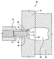
図1は第1の実施形態のMASD10の、流動不能位置での切欠き図である。MASD10は先端部13(または末端部)を有する吐出体12を具備し、先端部13はその中に出口15を画成する。出口15は出口ポートともよぶ。吐出体12はノズル、ノズル本体、または弁ともよぶが、説明を簡単にするために、以下、ノズル本体12とよぶ。ノズル本体12はまた、出口15につながる通路14をその中に画成する。MASD10はさらに出口カバー18も含む。図1の出口カバー18は金型組立体の片方の固定金型としても作用するが、図1および2に関する説明では出口カバー18とよぶ。片方の可動金型28は、(出口カバー18として示した)片方の固定金型と係合して、その中に金型のキャビティを画成する。作動時には、出口15と出口カバー18とは反復可能に互いと協働する。例えば、出口15と出口カバー18は、(図1に示す)流動不能位置と(図2に示す)流動可能位置との間を互いに対して能動的に移動する。「反復可能」とは、出口カバー18と出口15とが少なくとも一回反復可能に互いと協働することを意味する。極めて対照的に、揺変プラグは反復自在に出口と協働しない。なぜなら、揺変プラグは一回限りの使用品目で、一回だけ出口を掩蔽しその後は再使用されず(揺変プラグは金型のキャビティに吹き飛ばされる)、全く新しい揺変プラグが次のMASの金型キャビティへの吐出で形成されるからである。要するに、ノズル本体12はその中に出口15を画成し、出口カバー18は出口15と協働するが、出口カバー18は少なくとも一回出口15と協働するように構成される。
In each figure, the same reference numerals indicate the same components.
FIG. 1 is a cutaway view of the
流動不能位置では、出口カバー18は出口15を掩蔽し、覆われた出口15は、覆われた出口15の背後の通路14内に収容されたMASの流動を実質的に遮断する。図2に示すように、流動可能位置では、ノズル本体12は出口カバー18(すなわち片方の固定金型)に対して移動して、出口15が曝露される。この位置で、曝露された出口15はMASを金型キャビティ29へ自由に流動させる。
In the non-flowable position, the
MASD10を使用することにより、MASをスラリー状態に保持する十分な熱エネルギーがあれば、出口15での凍結した揺変プラグの形成が回避できる。要求される加熱効果は、ノズル本体12に連結される加熱器または、必要に応じて出口15に隣接設置されるその他の別の加熱器によりもたらされる。
By using the
有利なのは、出口15を覆った出口カバー18がほぼMASの出口15からの流れまたは移動を阻止するから、出口カバー18はほぼ出口からのMASの偶発的(すなわち過早または不測の)放出を阻止し、さらにまた揺変性成形機の生産性の低下のおそれを減じおよび/または操作者の付随的な火傷や怪我のおそれを低減する助けとなることである。
Advantageously, since the
MASD10は、揺変性成形機の円筒体に配置されたスクリュー機構(図示しないがMASD10に接続される)の動力学による逆の変化を避ける助けをする。揺変プラグの形成を回避することで、円筒体の圧力の変動を和らげることができる。円筒体の圧力が適度になると、キャビティ29での部品成形時に金型キャビティ29を充填する充填時間はより安定する。
The
揺変プラグの使用は揺変性成形機での円筒体とスクリュー機構とを必要とし、MASに大きな射程を強いることになる。円筒体の圧力が大きすぎると、キャビティ29を画成する金型組立体で金型のフラッシュ現象が起り、流動するMASは過早にキャビティ29に押しやられ、MASは金型組立体の各金型部分の間からはみ出す(または漏れる)だろう。この状態は、MASの漏洩またははみ出しの結果としてMASがキャビティ29に完全に詰め込まれる機会を与えられなかったことにより、欠陥成形部品または脆弱な成形部品を将来する。また、円筒体の圧力が低すぎると、キャビティ29で凍結現象が起り、MASは十分遠くまたは迅速にキャビティ29まで移動できない。そうすると移動の遅いMASは過早に凍結して、流動するMASのキャビティ29への完全な充填を阻止する。揺変吹付け圧の使用を回避することで円筒体の圧力は適正化され、上記のはみ出しと凍結との現象は回避される。
The use of a thundering plug requires a cylindrical body and a screw mechanism in a thixotropic molding machine, which imposes a large range on the MAS. If the pressure of the cylindrical body is too large, a mold flash phenomenon occurs in the mold assembly that defines the
出口カバー18は固定金型として示してある。しかし諒解されるように出口カバーは、適宜出口15に隣接配置されるその他の構造物、例えば金型ゲートインサート、金型組立体、あるいはホットランナー組立体であっても構わない。出口カバー18は、所望通りに出口15の掩蔽と曝露とに用いる出口カバーの表面20を呈する。第1の実施形態では、出口カバー表面20は出口15に直面しノズル本体12と共軸に滑動する。出口カバー18についてはその他の構成、例えば通路14内に弁棒(図示せず)を配置し、弁棒が移動して出口15に接触し、これが出口15を封止して覆われた出口15からのMASの流動を不能化することも考えられる。
The
出口カバー18は、ノズル本体12を収容する通路22を画成する。ノズル本体12は、出口カバー表面20に直面して出口カバー表面20と共軸に滑動する座部材16を呈する。
The
MASD10は熱エネルギー示差機構(図示せず)を含んでもよい。これは、局限基部で温度差を維持する加熱装置と冷却装置との組合せでよい。流動不能位置では、熱は出口15から除去でき、所望であれば出口15で十分にMASを固化することができる。この冷却効果は出口カバー18に出口15に隣接設置された冷却機構を使用して達成される。流動不能状態では、出口カバー18、または通路14に配されたMASのいずれか(または組合せ)により十分な熱がもたらされる。MASは出口15と通路14とに配されるが、もたらされた熱はMASをほぼスラリー状態に保持するに十分である。MASをスラリー状態に保持することにより凍結された揺変プラグの形成が回避されるのは有利である。
熱エネルギー示差機構は出口15を囲繞する所定の形状の構造物を含んでもよい。所定形状の構造物は加熱効果と冷却効果とを設定し維持する。この解決策は、加熱効果と冷却効果とを設定し維持する簡略化されたより経済的な構造物を可能にする。サーモグラフモデル化ソフトウエアを用いれば、出口15を囲繞する所定形状の構造物を確定できる。例えば、カリフォルニア州ゴリータのFLIRシステム社はサーモグラフモデル化ソフトウエアであるThermaGRAM(登録商標)の製造業者だが、このソフトウエアを使って熱エネルギー示差機構をモデル化し、ノズル本体12を囲繞する所定形状の構造物を確定できる。
The thermal energy differential mechanism may include a structure having a predetermined shape surrounding the
MASD10は、ノズル本体12、出口カバー18、および金型組立体のいずれか、およびこれらの適当な組合せに能動的に結合されたインターロック組立体(図示せず)を含んでもよい。インターロック組立体は、金型の各片方または各部分18、28が互いから偏位または変位したとき、出口15と出口カバー18との相対運動を阻止する。インターロック組立体は、MAS10が金型組立体と協働しなくなると、MASD10によるMAS吐出を阻止するように作用して、出口15からの溶融原料の偶発的放出を阻止する(例えば、可動金型28が固定金型18に当接しなくなるとき)。
第1の実施形態については、出口カバー18はノズル本体12の外側にある。出口カバー18は出口15に対して相対的に滑動しまたは関着する。これの例は回転締切弁である。ノズル本体12は、ノズル本体12を通過するその長手方向軸に沿って軸方向に移動する。ノズル本体12は揺変性成形機の円筒体に取り付けられる。円筒体は出口カバー18内で先端部13を往復運動させるように駆動され、ノズル本体12は、出口カバー18で画成される通路22に沿ってその中を滑動する。一方、以下に述べる別の実施形態では、ノズル本体12は出口カバー18に対して静止する。
For the first embodiment, the
MAS10は金属合金スラリー成形機(図示せず)の円筒体(図示せず)の末端部に接続できる。MAS10は金属合金スラリーホットランナー組立体(図示せず)で画成されるホットランナー通路に接続できる。MAS10は金属合金スラリー成形用組立体で画成される通路に接続できる。諒解されるように、MAS10はこれらの組立体とは別個に供給される。
The
座部材16と出口カバー18との間には隙間が画成される。具体的には隙間は出口カバー表面20と座部材16との間に存在する。少量のMASは隙間へ至る道に出くわしMAS層を生成する。MAS層は、MASのキャビティ29への射出中に冷却できる。こうしてMAS層を固化状態に冷却することで、固化されたMAS層は、MASが(圧力の下)キャビティ29へ射出されるあいだ追加のMASがさらに隙間に押し込まれるのを阻止または妨害する。MASの固化層は(出口15が掩蔽される)ノズル12の後退中に加熱でき、ノズル本体12がキャビティ29から遠くへ後退するあいだに摩擦は少なくなる。
A gap is defined between the
図2は図1のMASD10の、流動可能位置での切欠き図である。この位置で、揺変性成形機のスクリューと円筒体とはMASに射出圧をかける。ノズル本体12は前方へ(つまり通路22と流体連通に設置された金型のキャビティ29に向って)移動する。事実上、出口カバー18は出口15に対して相対的に移動するから(出口カバー18はこの実施形態では静止したままである)、出口カバー18はもう出口を掩蔽しない。この位置で、曝露された出口15は今や通路22と流体連通してMASの流れ24を実現する。曝露した出口15は、出口15からキャビティ29へのMASの自由な流れを可能にする。
FIG. 2 is a cutaway view of the
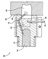
図3は第2の実施形態(これが好ましい実施形態)のMASD30の、流動不能位置での切欠き図である。同図で好ましい構造と形状とが示してある。出口カバー32を用いるから、固定金型部分18はもう、先に図1および2で示した出口カバーのところで作用しない。出口カバー32を好ましい実施形態用の締切体32と呼ぶ。
FIG. 3 is a cutaway view of the
固定金型18はキャビティ29を画成し、締切体32はボルト組立体(図示せず)により固定金型18に固定的に取り付けられる。ボルト33は加熱器34を締切体32に取り付ける。締切体32には加熱器34、冷却装置36、および温度センサ38(例えば熱電対など)が取り付けられる。締切体32に加熱器34、冷却装置36、および温度センサ38を取り付ければ、加熱器34および/または冷却装置36および/または温度センサ38に保守業務が必要な場合、締切体32を取り外して代替の締切体32を再挿着できるという利点を提供する。
The
掩蔽出口15の背後領域と通路22との熱エネルギーの差(勾配)は、追加の加熱および冷却用の構造要素によりさらに大きくできる。これらの構造物を用いる利点は、必要とされる局限の加熱および冷却効果をさらに高めることにある。
The thermal energy difference (gradient) between the area behind the
MASD30はまた、ノズル本体12に能動的に連結されたノズル加熱装置40または42を含んでもよい。ノズル加熱装置40は出口15内に収容されたMASをスラリー状態に維持する。
The
MASD30はさらに、締切体32に能動的に連結された出口カバー加熱装置34を含んでもよい。装置34は、MASD30が流動不能位置にあるとき、出口15に配されたMASを、それが出口15に滞留する間にほぼスラリー状態に維持する。
The
MASD30はさらに、締切体32、または出口15直近の構造物に能動的に連結される出口カバー冷却装置36を含んでもよい。装置36は導管を画成または提供し、導管はその中の冷却流体を搬送する。装置36は、締切体32とノズル本体12との間に画成される隙間に置かれたMASを固化状態に冷却する。この形状構成は向上した冷却効果をもたらし、流動可能位置で、隙間内に置かれた固化MASを用いて、MASの流れが通路22から隙間へ入り込まないようにすることができる。隙間は締切体32とノズル本体12との間に画成される。
The
熱量を変動または変化させることは冷却量を変化させるのに比して難しいことが分かっているから、加熱効果は比較的一定に保ち、冷却効果を変化させる。 Since it has been found that changing or changing the amount of heat is more difficult than changing the amount of cooling, the heating effect is kept relatively constant and the cooling effect is changed.
図4は、流動可能位置にある、図3のMASD30の切欠き図である。この位置で、ノズル本体12は揺変性成形機の円筒体により移動または変位しており、出口15はもう締切体32で掩蔽されていない。結果として、MASは曝露された出口15から流動できる(24)。
FIG. 4 is a cutaway view of
図5は第3の実施形態によるMASD50の、流動不能位置での切欠き図である。この位置で、締切体32は出口カバーのところで作用する。締切体32は動かされるが、ノズル本体12は動かされない。第3の実施形態はホットランナーマニホルド組立体に使用でき、図5には固定金型58に取り付けられた第3の実施形態が示してある。ホットランナー組立体(図示せず)はノズル本体12に結合される。
FIG. 5 is a cutaway view of the
MASD50は、固定金型58で画成されるキャビティ59内に嵌まるように形成された止め子52を含む。止め子52と締切体32との間にはばね54を配置する。
The
流動不能位置で、金型の可動側60は付勢された金型クランプ(図示せず)により動かされる。これにより金型の可動側60は固定金型58から偏位し、同様に締切体32からも偏位または移動する。締切体32から遠ざかる方に移動する金型組立体60の動きに応じて、ばね54は締切体32を可動金型部分60の方へ移動するように付勢する。移動した締切体32の一部はこのとき出口15を掩蔽し、覆われた出口15は通路14内に配されたMASの流れを無力化または遮断する。総じて、流動不能位置で、締切体32は可動金型部分60が固定金型58から遠ざかる方に移動する動きに応じて移動し、その結果移動した締切体32は出口15を覆う。加熱器56はノズル本体12に取り付けられるが、別の加熱器34を締切体32に取り付けてもよい。締切体32は、出口15と相互作用する出口カバー表面を呈する。
In the non-flowable position, the
図6は、流動可能位置にある図5のMASD50の切欠き図である。総じて、流動可能位置で、締切体32は、締切体32に向って移動しこれに当接する金型の片方60に応じて移動する。移動した締切体32は出口15から偏位し、MASは曝露された出口15から流動(24)できる。具体的には、可動金型60が動かされて締切体32を押し付けると、締切体32は止め子52側に変位する(そしてばね54が圧縮される)。金型のキャビティ62は締切体32の通路22と一直線になる。止め子52側に移動する締切体32に応じて、締切体はもう出口15を覆わないから、出口15内に収容されたMASは制限なしに自由に流動できる(24)。
FIG. 6 is a cutaway view of
図7は第4の実施形態のMASD70の、流動不能位置での切欠き図である。MASD70は、締切体72として示した出口カバーを含む。締切体72を心棒と呼んでもいい。ノズル本体12はその中にキャビティ74を画成し、キャビティ74はその中に締切体72を滑動可能に収容する。締切体72はキャビティ72内を滑動して出口15を交互に覆って曝露する。ノズル本体12はさらに、通路74からノズル本体12の外側縁部に向けて伸びる別の通路78も画成する。通路78内には、締切体72に接続する保持棒76を配置する。保持棒76は図示されない機構により外部から駆動する。例えば、保持棒76の一方の端部を締切体72に結合し、保持棒76の他端(図示せず)を液圧式や空圧式、電気的、または機械的駆動組立体に取り付けてもよい。棒76の駆動時に、締切体72を出口閉位置と出口開位置との間で移動させる。このようにして、締切体72の駆動は直接金型組立体の動作に依存させずに、仲介駆動機構として作用する駆動機構を介して間接的に金型組立体の動作に依存させてもよい。金型組立体が直接駆動機構に作用し、駆動機構が棒76を駆動してもよい。
FIG. 7 is a cutaway view of the
図8は流動可能位置にある図7のMASDの切欠き図である。同図で締切体72は(棒76により)出口15から遠ざかって後退し出口15を曝露している。
FIG. 8 is a cutaway view of the MASD of FIG. 7 in a flowable position. In this figure, the cut-off
諒解されるように一部の要素は特定の条件または機能のために変更することができる。上述のコンセプトはさらにその他の多様な用途に広げることができるが、それらは本発明の範囲内にあるのは明らかである。上記の如く実施形態を記述したが、上述のコンセプトから逸脱することなく変型および強化が可能なことは当業者には明らかである。したがって、特許文面による保護はクレームの範囲によってのみ制限されるべきである。 As will be appreciated, some elements can be modified for specific conditions or functions. The above concepts can be further extended to a variety of other applications, but they are clearly within the scope of the present invention. While embodiments have been described above, it will be apparent to those skilled in the art that modifications and enhancements can be made without departing from the concepts described above. Therefore, patent protection should be limited only by the scope of the claims.
Claims (11)
溶融合金スラリーを流すための一の通路を内部に有する吐出体であって、その一の通路の出口が前記吐出体の外面上に画定されている前記吐出体と、
他の通路を有し、前記金型と接触可能に配置される出口カバーであって、前記吐出体の前記出口から吐出された溶融合金スラリーを前記出口カバーの前記他の通路を介して前記金型の前記キャビティ内に導入する前記出口カバーと備え、
前記吐出体は、流動不能位置と流動可能位置との間で、前記出口カバー内を前記吐出体の前記外面が前記出口カバー内表面に直面するように前記出口カバーに対して相対的に滑動可動であって、
前記流動不能位置では、前記出口カバーの前記内表面が前記吐出体の前記出口を遮蔽して前記吐出体の前記一の通路中に保持された金属合金スラリーの流動を遮断し、
前記流動可能位置では、前記出口カバーは前記吐出体の前記出口を遮蔽せずに、前記吐出体の前記出口から前記出口カバーの前記他の通路を通って前記金型のキャビティ内へ金属合金スラリーの流動を可能とし、
前記流動不能位置において、前記出口と隣接しかつその出口の外側における部材から除去される熱は、前記出口カバーと前記吐出体との間の隙間における金属合金スラリーを固化させるに十分であることを特徴とする金属合金スラリー吐出装置。A metal alloy slurry discharge device that discharges molten alloy slurry into a cavity of a mold,
A discharge body having a passage for flowing molten alloy slurry therein, the discharge body having an outlet defined on the outer surface of the discharge body;
An outlet cover having another passage and disposed so as to be in contact with the mold, wherein the molten alloy slurry discharged from the outlet of the discharge body is passed through the other passage of the outlet cover. With the outlet cover for introduction into the cavity of the mold,
The discharge body is slidable relative to the outlet cover between the non-flowable position and the flowable position so that the outer surface of the discharge body faces the inner surface of the outlet cover in the outlet cover. Because
In the non-flowable position, the inner surface of the outlet cover shields the outlet of the discharge body and blocks the flow of the metal alloy slurry held in the one passage of the discharge body,
In the flowable position, the outlet cover does not shield the outlet of the discharge body, and passes from the outlet of the discharge body to the cavity of the mold through the other passage of the outlet cover. The flow of
The heat removed from the member adjacent to the outlet and outside the outlet at the non-flowable position is sufficient to solidify the metal alloy slurry in the gap between the outlet cover and the discharge body. A metal alloy slurry discharging apparatus characterized by the above.
溶融合金スラリーを流すための一の通路を内部に有する吐出体であって、その一の通路の出口が前記吐出体の外面上に画定されている前記吐出体と、
他の通路を有し、前記金型と接触可能に配置される出口カバーであって、前記吐出体の前記出口から吐出された溶融合金スラリーを前記出口カバーの前記他の通路を介して前記金型の前記キャビティ内に導入する前記出口カバーと備え、
前記吐出体は、流動不能位置と流動可能位置との間で、前記出口カバー内を前記吐出体の前記外面が前記出口カバー内表面に直面するように前記出口カバーに対して相対的に滑動可動であって、
前記吐出体が移動して、または前記金型の少なくとも一部の移動に応じて前記出口カバーが移動して、前記流動不能位置に至ると、前記出口カバーの前記内表面が前記吐出体の前記出口を遮蔽して前記吐出体の前記一の通路中に保持された金属合金スラリーの流動を遮断し、
前記吐出体が移動して、または前記金型の少なくとも一部の移動に応じて前記出口カバーが移動して、前記流動可能位置に至ると、前記出口カバーは前記吐出体の前記出口を遮蔽せずに、前記吐出体の前記出口から前記出口カバーの前記他の通路を通って前記金型のキャビティ内へ金属合金スラリーの流動を可能とすることを特徴とする金属合金スラリー吐出装置。A metal alloy slurry discharge device that discharges molten alloy slurry into a cavity of a mold,
A discharge body having a passage for flowing molten alloy slurry therein, the discharge body having an outlet defined on the outer surface of the discharge body;
An outlet cover having another passage and disposed so as to be in contact with the mold, wherein the molten alloy slurry discharged from the outlet of the discharge body is passed through the other passage of the outlet cover. With the outlet cover for introduction into the cavity of the mold,
The discharge body is slidable relative to the outlet cover between the non-flowable position and the flowable position so that the outer surface of the discharge body faces the inner surface of the outlet cover in the outlet cover. Because
When the discharge body moves or the outlet cover moves according to the movement of at least a part of the mold and reaches the non-flowable position , the inner surface of the outlet cover is moved to the discharge body. Shielding the flow of the metal alloy slurry held in the one passage of the discharge body by shielding the outlet;
When the discharge body moves or the outlet cover moves in response to movement of at least a part of the mold and reaches the flowable position , the outlet cover shields the outlet of the discharge body. not to the other metal alloy slurry ejection apparatus characterized by allowing the flow of metal alloy slurry through the passageway into the mold cavity of the outlet cover from the outlet of the discharge body.
溶融合金スラリーを流すための一の通路を内部に有する吐出体であって、その一の通路の出口が前記吐出体の外面上に画定されている前記吐出体と、
他の通路を有し、前記金型と接触可能に配置される出口カバーであって、前記吐出体の前記出口から吐出された溶融合金スラリーを前記出口カバーの前記他の通路を介して前記金型の前記キャビティ内に導入する前記出口カバーと備え、
前記吐出体は、流動不能位置と流動可能位置との間で、前記出口カバー内を前記吐出体の前記外面が前記出口カバー内表面に直面するように前記出口カバーに対して相対的に滑動可動であって、
前記流動不能位置では、前記出口カバーの前記内表面が前記吐出体の前記出口を遮蔽して前記吐出体の前記一の通路中に保持された金属合金スラリーの流動を遮断し、
前記流動可能位置では、前記出口カバーは前記吐出体の前記出口を遮蔽せずに、前記吐出体の前記出口から前記出口カバーの前記他の通路を通って前記金型のキャビティ内へ金属合金スラリーの流動を可能とし、
前記出口カバーから変位する前記金型の動きに応じて前記出口カバーは移動して、前記流動不能位置で、その移動した出口カバーは前記出口を覆うことを特徴とする金属合金スラリー吐出装置。A metal alloy slurry discharge device that discharges molten alloy slurry into a cavity of a mold,
A discharge body having a passage for flowing molten alloy slurry therein, the discharge body having an outlet defined on the outer surface of the discharge body;
An outlet cover having another passage and disposed so as to be in contact with the mold, wherein the molten alloy slurry discharged from the outlet of the discharge body is passed through the other passage of the outlet cover. With the outlet cover for introduction into the cavity of the mold,
The discharge body is slidable relative to the outlet cover between the non-flowable position and the flowable position so that the outer surface of the discharge body faces the inner surface of the outlet cover in the outlet cover. Because
In the non-flowable position, the inner surface of the outlet cover shields the outlet of the discharge body and blocks the flow of the metal alloy slurry held in the one passage of the discharge body,
In the flowable position, the outlet cover does not shield the outlet of the discharge body, and passes from the outlet of the discharge body to the cavity of the mold through the other passage of the outlet cover. The flow of
The metal alloy slurry discharging apparatus according to claim 1, wherein the outlet cover moves in accordance with the movement of the mold displaced from the outlet cover , and the moved outlet cover covers the outlet at the non- flowable position.
前記吐出体に動作可能に結合されている吐出装置加熱装置であって、溶融状態において前記出口内にある溶融金属合金スラリーを維持する吐出装置加熱装置を備える金属合金スラリー吐出装置。The metal alloy slurry discharge device according to any one of claims 1 to 4,
A discharge device heating device operably coupled to the discharge body, comprising: a discharge device heating device that maintains a molten metal alloy slurry in the outlet in a molten state.
前記出口カバーと動作可能に連結されている出口カバー加熱装置であって、前記流動可能位置にある間、前記出口に留まりながら、溶融状態において前記出口内にある溶融金属合金スラリーを維持することを特徴とする金属合金スラリー吐出装置。A metal alloy slurry discharge device according to any one of claims 1 to 5,
An outlet cover heating device operably connected to the outlet cover, wherein the molten metal alloy slurry in the outlet is maintained in a molten state while remaining at the outlet while in the flowable position. A metal alloy slurry discharging apparatus characterized by the above.
前記出口カバーと動作可能に連結されている出口カバー冷却装置であって、前記出口カバーと前記吐出体との間に画定される隙間にある溶融金属合金スラリーを固化状態にまで冷却する前記出口カバー冷却装置を具備することを特徴とする金属合金スラリー吐出装置。The metal alloy slurry discharge device according to any one of claims 1 to 6,
An outlet cover cooling device operably connected to the outlet cover, wherein the outlet cover cools the molten metal alloy slurry in a gap defined between the outlet cover and the discharge body to a solidified state. A metal alloy slurry discharge device comprising a cooling device.
前記出口カバーは前記吐出体の外側に配置されることを特徴とする金属合金スラリー吐出装置。The metal alloy slurry discharge device according to any one of claims 1 to 7,
The metal alloy slurry discharge device, wherein the outlet cover is disposed outside the discharge body.
前記出口カバーは前記出口に対して摺動可能であることを特徴とする金属合金スラリー吐出装置。The metal alloy slurry discharge device according to any one of claims 1 to 8,
The metal alloy slurry discharge device, wherein the outlet cover is slidable with respect to the outlet.
前記出口カバーは締切部材を具備し、
前記出口カバーの前記出口を遮蔽する前記出口カバーの前記内表面は、その締切部材の面であることを特徴とする金属合金スラリー吐出装置。A metal alloy slurry discharge device according to any one of claims 1 to 9,
The outlet cover includes a cutoff member;
The metal alloy slurry discharging apparatus according to claim 1, wherein the inner surface of the outlet cover that shields the outlet of the outlet cover is a surface of a cutoff member.
前記吐出体はその中を貫通する軸線を含み、前記出口カバーの内表面は前記出口に直面し、前記吐出体と同軸で摺動することを特徴とする金属合金スラリー吐出装置。The metal alloy slurry discharge device according to claim 1,
The discharge body includes an axis extending therethrough, and the inner surface of the outlet cover faces the outlet and slides coaxially with the discharge body.
Applications Claiming Priority (3)
| Application Number | Priority Date | Filing Date | Title |
|---|---|---|---|
| US11/120,223 | 2005-05-02 | ||
| US11/120,223 US7341094B2 (en) | 2005-05-02 | 2005-05-02 | Metallic alloy slurry dispenser |
| PCT/CA2006/000527 WO2006116838A2 (en) | 2005-05-02 | 2006-04-05 | A metallic alloy slurry dispenser |
Publications (3)
| Publication Number | Publication Date |
|---|---|
| JP2008540128A JP2008540128A (en) | 2008-11-20 |
| JP2008540128A5 JP2008540128A5 (en) | 2009-03-12 |
| JP5121701B2 true JP5121701B2 (en) | 2013-01-16 |
Family
ID=37233303
Family Applications (1)
| Application Number | Title | Priority Date | Filing Date |
|---|---|---|---|
| JP2008509273A Expired - Fee Related JP5121701B2 (en) | 2005-05-02 | 2006-04-05 | Metal alloy slurry dispenser |
Country Status (14)
| Country | Link |
|---|---|
| US (3) | US7341094B2 (en) |
| EP (1) | EP1896205B1 (en) |
| JP (1) | JP5121701B2 (en) |
| KR (1) | KR100977661B1 (en) |
| CN (1) | CN101663113B (en) |
| AT (1) | ATE473822T1 (en) |
| AU (1) | AU2006243698B2 (en) |
| BR (1) | BRPI0610109A2 (en) |
| CA (1) | CA2605263C (en) |
| DE (1) | DE602006015469D1 (en) |
| MX (1) | MX2007013608A (en) |
| RU (1) | RU2371281C2 (en) |
| TW (1) | TWI290497B (en) |
| WO (1) | WO2006116838A2 (en) |
Families Citing this family (14)
| Publication number | Priority date | Publication date | Assignee | Title |
|---|---|---|---|---|
| US20070131375A1 (en) * | 2005-12-09 | 2007-06-14 | Husky Injection Molding Systems Ltd. | Thixo-molding shot located downstream of blockage |
| FR2899510B1 (en) * | 2006-04-11 | 2010-09-10 | Michelin Soc Tech | METHOD AND DEVICE FOR MOLDING ELASTOMERIC ARTICLES |
| US20090000758A1 (en) | 2007-04-06 | 2009-01-01 | Ashley Stone | Device for Casting |
| US20100032123A1 (en) * | 2008-08-05 | 2010-02-11 | Ratte Robert W | Molding of die-cast product and method of |
| US8327914B2 (en) * | 2009-11-06 | 2012-12-11 | National Research Council Of Canada | Feeding system for semi-solid metal injection |
| US8376026B2 (en) * | 2010-01-29 | 2013-02-19 | National Research Council Of Canada | Thixotropic injector with improved annular trap |
| CN102092118B (en) * | 2010-12-22 | 2013-07-17 | 吉林大学珠海学院 | Spring slide valve type nozzle device |
| AT517240B1 (en) * | 2015-06-05 | 2018-04-15 | Ltc Gmbh | Barrel for a thixomolding device |
| JP6845612B2 (en) * | 2016-03-07 | 2021-03-17 | 中村留精密工業株式会社 | Measurement method and equipment for machine accuracy in machine tools |
| CN105880540A (en) * | 2016-06-23 | 2016-08-24 | 吴江市液铸液压件铸造有限公司 | Cooler for liquid casting distributor |
| CN107020363A (en) * | 2017-05-05 | 2017-08-08 | 广东鸿图武汉压铸有限公司 | A kind of monoblock type pouring bushing for die casting die |
| CN109332641A (en) * | 2018-09-30 | 2019-02-15 | 东莞市天禹五金科技有限公司 | A kind of production mould and its production technology of connector shell |
| CN109954858A (en) * | 2019-04-17 | 2019-07-02 | 昆明理工大学 | A kind of semi-solid slurrying forming integrated method |
| US11883879B1 (en) * | 2022-09-07 | 2024-01-30 | Additive Technologies, LLC | System and method for controlling flow through a 3D printer |
Family Cites Families (24)
| Publication number | Priority date | Publication date | Assignee | Title |
|---|---|---|---|---|
| US3401426A (en) * | 1966-05-31 | 1968-09-17 | New Britain Machine Co | Plastic injection molding machine |
| US4386903A (en) * | 1981-05-01 | 1983-06-07 | Husky Injection Molding Systems Ltd. | Injection-molding machine with hydraulic mold clamping |
| US4678427A (en) * | 1985-11-04 | 1987-07-07 | Husky Injection Molding System Ltd. | Automatic shut off nozzle for plastic extruder |
| US5040589A (en) | 1989-02-10 | 1991-08-20 | The Dow Chemical Company | Method and apparatus for the injection molding of metal alloys |
| US4922082A (en) | 1989-03-17 | 1990-05-01 | Axiomatics Corporation | Thermal valve gate for plastic molding apparatus |
| DE19531161C2 (en) * | 1995-08-24 | 1999-05-20 | Frech Oskar Gmbh & Co | Hot chamber die casting machine |
| DE19548687B4 (en) * | 1995-12-23 | 2004-01-08 | EWIKON Heißkanalsysteme GmbH & Co KG | Heated valve gate |
| DE19615029C2 (en) * | 1996-02-26 | 1998-07-02 | Richard Herbst | Injection molding tool for smart cards |
| EP0791448A3 (en) * | 1996-02-26 | 1999-05-12 | HERBST, Richard | Method and apparatus for injection moulding of plastic articles |
| US5975127A (en) * | 1996-02-28 | 1999-11-02 | Dray; R. F. | Shut-off valve |
| JP3329651B2 (en) * | 1996-03-07 | 2002-09-30 | 株式会社日本製鋼所 | Liquid phase injection molding of metal |
| US5785915A (en) * | 1996-09-13 | 1998-07-28 | Osuna-Diaz; Jesus M. | Injection molding with annular gate and sleeve shutoff valve |
| US6056536A (en) * | 1997-03-20 | 2000-05-02 | Husky Injection Molding Systems Ltd. | Valve gating apparatus for injection molding |
| US5928578A (en) * | 1997-03-26 | 1999-07-27 | Avalon Imaging, Inc. | Skip-eject system for injection molding machines |
| US6540006B2 (en) * | 1998-03-31 | 2003-04-01 | Takata Corporation | Method and apparatus for manufacturing metallic parts by fine die casting |
| US6203311B1 (en) * | 1998-05-04 | 2001-03-20 | Robert F. Dray | Sliding ring non-return valve |
| JP3268268B2 (en) * | 1998-05-26 | 2002-03-25 | 幸久 長子 | Automatic hot water injection system |
| WO2000047352A1 (en) * | 1999-02-10 | 2000-08-17 | Ju-Oh Inc. | Metal mold of hot runner type injection molding machine and method of manufacturing the metal mold |
| JP2000326062A (en) * | 1999-05-21 | 2000-11-28 | Kobe Steel Ltd | Method and device for injection molding of light alloy and nozzle used for the same |
| US6357511B1 (en) * | 2000-10-26 | 2002-03-19 | Husky Injection Molding Systems, Ltd. | Injection nozzle for a metallic material injection-molding machine |
| JP2002347084A (en) * | 2001-05-23 | 2002-12-04 | Esuipi Kk | Hot runner mold device for injection molding |
| CA2450411C (en) * | 2002-11-21 | 2012-01-03 | Mold-Masters Limited | Hot runner nozzle with a tip, a tip surrounding piece and an alignment piece |
| BR0318153A (en) * | 2003-03-06 | 2006-02-21 | Husky Injection Molding | jito appliance |
| US7284978B2 (en) * | 2005-06-30 | 2007-10-23 | Husky Injection Molding Systems Ltd. | Brake for molding machine valve |
-
2005
- 2005-05-02 US US11/120,223 patent/US7341094B2/en not_active Expired - Fee Related
-
2006
- 2006-04-05 AU AU2006243698A patent/AU2006243698B2/en not_active Ceased
- 2006-04-05 CN CN2006800151819A patent/CN101663113B/en not_active Expired - Fee Related
- 2006-04-05 AT AT06721780T patent/ATE473822T1/en not_active IP Right Cessation
- 2006-04-05 EP EP06721780A patent/EP1896205B1/en not_active Not-in-force
- 2006-04-05 JP JP2008509273A patent/JP5121701B2/en not_active Expired - Fee Related
- 2006-04-05 DE DE602006015469T patent/DE602006015469D1/en active Active
- 2006-04-05 BR BRPI0610109-7A patent/BRPI0610109A2/en not_active IP Right Cessation
- 2006-04-05 WO PCT/CA2006/000527 patent/WO2006116838A2/en active Application Filing
- 2006-04-05 MX MX2007013608A patent/MX2007013608A/en active IP Right Grant
- 2006-04-05 KR KR1020077028032A patent/KR100977661B1/en not_active IP Right Cessation
- 2006-04-05 RU RU2007144611/02A patent/RU2371281C2/en not_active IP Right Cessation
- 2006-04-05 CA CA2605263A patent/CA2605263C/en not_active Expired - Fee Related
- 2006-04-21 TW TW095114371A patent/TWI290497B/en not_active IP Right Cessation
-
2007
- 2007-07-23 US US11/781,408 patent/US20080011448A1/en not_active Abandoned
- 2007-07-23 US US11/781,401 patent/US20080011447A1/en not_active Abandoned
Also Published As
| Publication number | Publication date |
|---|---|
| RU2371281C2 (en) | 2009-10-27 |
| ATE473822T1 (en) | 2010-07-15 |
| EP1896205B1 (en) | 2010-07-14 |
| US7341094B2 (en) | 2008-03-11 |
| US20080011447A1 (en) | 2008-01-17 |
| US20080011448A1 (en) | 2008-01-17 |
| JP2008540128A (en) | 2008-11-20 |
| CA2605263A1 (en) | 2006-11-09 |
| CN101663113A (en) | 2010-03-03 |
| MX2007013608A (en) | 2008-01-24 |
| BRPI0610109A2 (en) | 2010-05-25 |
| EP1896205A2 (en) | 2008-03-12 |
| DE602006015469D1 (en) | 2010-08-26 |
| KR20080007274A (en) | 2008-01-17 |
| WO2006116838A2 (en) | 2006-11-09 |
| TWI290497B (en) | 2007-12-01 |
| EP1896205A4 (en) | 2009-03-04 |
| AU2006243698B2 (en) | 2009-08-20 |
| TW200702081A (en) | 2007-01-16 |
| AU2006243698A1 (en) | 2006-11-09 |
| RU2007144611A (en) | 2009-06-10 |
| US20060243416A1 (en) | 2006-11-02 |
| CA2605263C (en) | 2010-03-30 |
| KR100977661B1 (en) | 2010-08-24 |
| CN101663113B (en) | 2012-07-25 |
Similar Documents
| Publication | Publication Date | Title |
|---|---|---|
| JP5121701B2 (en) | Metal alloy slurry dispenser | |
| JP2008540128A5 (en) | ||
| EP2782692B1 (en) | Diecasting nozzle and method for operating a diecasting nozzle | |
| US7387154B2 (en) | Metallic-molding-material runner having equilibrated flow | |
| KR20000011472A (en) | semimelt-injecting method and apparatns of metal | |
| EP1934005B1 (en) | Die casting method | |
| JP2010094937A (en) | Side valve gate type hot runner system | |
| JP4156748B2 (en) | Metal injection molding method and apparatus, and molded product | |
| JP5958207B2 (en) | Die casting method | |
| JP2007061880A (en) | Injection molding apparatus | |
| EP0992333A1 (en) | Injection device of plunger type injection molding machine | |
| DE10334766A1 (en) | Casting mold and method for casting a metal object | |
| JP3502575B2 (en) | Mold for forming metal molded products | |
| JP2011143446A (en) | Apparatus and method for pressure-casting half-solidified metal | |
| JP4359826B2 (en) | Metal material forming equipment | |
| JP2004249344A (en) | Injection molding method and injection molding device of light alloy | |
| JP3677738B2 (en) | Injection plunger with ring valve for metal material molding | |
| JP2004243366A (en) | Die-casting equipment | |
| KR20080065144A (en) | The temperature control system for diecasting machine sleeve | |
| JP3677735B2 (en) | Metal material injection molding method | |
| JP2004025291A (en) | Injection molding method and injection molding apparatus for light alloy | |
| PL190635B1 (en) | Magnesium die casting process | |
| JP2004322200A (en) | Injection unit of molten metal former | |
| JPH0985782A (en) | Method and structure of preventing sagging phenomenon in injection molding machine | |
| JPH0671414A (en) | Die for forging molten metal |
Legal Events
| Date | Code | Title | Description |
|---|---|---|---|
| A521 | Request for written amendment filed |
Free format text: JAPANESE INTERMEDIATE CODE: A523 Effective date: 20090122 |
|
| A621 | Written request for application examination |
Free format text: JAPANESE INTERMEDIATE CODE: A621 Effective date: 20090122 |
|
| A621 | Written request for application examination |
Free format text: JAPANESE INTERMEDIATE CODE: A621 Effective date: 20090122 |
|
| A977 | Report on retrieval |
Free format text: JAPANESE INTERMEDIATE CODE: A971007 Effective date: 20110830 |
|
| A131 | Notification of reasons for refusal |
Free format text: JAPANESE INTERMEDIATE CODE: A131 Effective date: 20110907 |
|
| A521 | Request for written amendment filed |
Free format text: JAPANESE INTERMEDIATE CODE: A523 Effective date: 20111207 |
|
| A131 | Notification of reasons for refusal |
Free format text: JAPANESE INTERMEDIATE CODE: A131 Effective date: 20120206 |
|
| A521 | Request for written amendment filed |
Free format text: JAPANESE INTERMEDIATE CODE: A523 Effective date: 20120507 |
|
| A131 | Notification of reasons for refusal |
Free format text: JAPANESE INTERMEDIATE CODE: A131 Effective date: 20120604 |
|
| A521 | Request for written amendment filed |
Free format text: JAPANESE INTERMEDIATE CODE: A523 Effective date: 20120831 |
|
| TRDD | Decision of grant or rejection written | ||
| A01 | Written decision to grant a patent or to grant a registration (utility model) |
Free format text: JAPANESE INTERMEDIATE CODE: A01 Effective date: 20120925 |
|
| A01 | Written decision to grant a patent or to grant a registration (utility model) |
Free format text: JAPANESE INTERMEDIATE CODE: A01 |
|
| A61 | First payment of annual fees (during grant procedure) |
Free format text: JAPANESE INTERMEDIATE CODE: A61 Effective date: 20121023 |
|
| FPAY | Renewal fee payment (event date is renewal date of database) |
Free format text: PAYMENT UNTIL: 20151102 Year of fee payment: 3 |
|
| R150 | Certificate of patent or registration of utility model |
Free format text: JAPANESE INTERMEDIATE CODE: R150 |
|
| LAPS | Cancellation because of no payment of annual fees |