JP5121604B2 - Folding stroller - Google Patents
Folding stroller Download PDFInfo
- Publication number
- JP5121604B2 JP5121604B2 JP2008176106A JP2008176106A JP5121604B2 JP 5121604 B2 JP5121604 B2 JP 5121604B2 JP 2008176106 A JP2008176106 A JP 2008176106A JP 2008176106 A JP2008176106 A JP 2008176106A JP 5121604 B2 JP5121604 B2 JP 5121604B2
- Authority
- JP
- Japan
- Prior art keywords
- pair
- portions
- infant
- seat
- elastic
- Prior art date
- Legal status (The legal status is an assumption and is not a legal conclusion. Google has not performed a legal analysis and makes no representation as to the accuracy of the status listed.)
- Active
Links
Images


Landscapes
- Carriages For Children, Sleds, And Other Hand-Operated Vehicles (AREA)
Description
本発明は、例えば乳幼児等が乗車するための折畳式ベビーカーに関するものである。 The present invention relates to a folding stroller for an infant or the like to ride.
従来より、乳幼児等が乗車するためのベビーカーが用いられている。そして、このようなベビーカーの中でも、不使用時にはコンパクトに折畳みが可能で、軽量である、いわゆる折畳式ベビーカーが、持ち運びに便利であり、保管場所も省スペースで良いなどの理由から普及している。このような折畳式ベビーカーは、左右の一対の把持部と、左右前後の車輪を有し、左右の前輪を回動自在に連結する一対の前輪軸部と、同様に左右の後輪と連結する一対の後輪軸部と、を有している。そして、側面視で後輪軸部は、前輪軸部を斜めに支えるようになっている。この折畳式ベビーカーを折畳む際には、左右の一対の把持部、前輪軸部、後輪軸部、前輪、後輪はそれぞれ、左右の間隔を狭める方向に畳まれ、前輪軸部を把持部の方向に回動させて、後輪軸部と前輪軸部とが略同一線上となるようにすると、コンパクトに収容することができる。そして、このようなベビーカーは、折畳まれた状態で重量を支えて自立させて収容することができるようになっている。つまり、このようなベビーカーは折畳むと自立脚が出てくるようになっており、自立脚と後輪または前輪とでベビーカーの重量を支えて、自立して収容できるようになっている。また、折畳んだ状態では、把持部がちょうど傘の柄のような形状であることから、アンブレラタイプと称することもある。或いは、このような折畳んだ状態が、コンパクトで、軽量であり、持ち運びが便利で、収容するスペースが省スペースで良いような折畳式ベビーカーは、バギータイプのベビーカーと称することもある。(例えば、特許文献1及び特許文献2)。
このような、折畳式ベビーカーは、軽量化やコンパクト化を追及するものであるので、乳幼児が着座する座席部分の衝撃緩和性が不十分であり、座り心地のあまり良くないものが多い。また、着座している乳幼児が動いたり、走行時の路面の凹凸などのゆれなどに対応しきれずに、乳幼児が飛び出し、怪我をする等の恐れもある。このため、通常は、折畳式ベビーカーは、座席部分に背面側から左右の両肩に配置される一対の肩帯部と前股部分に配置される前股帯部とが設けられており、乳幼児を着座させた後に、この一対の肩帯部と前股帯部とを乳幼児の腹部部分で留めて乳幼児の身体が座席部に固定されるようになっている。しかし、乳幼児の身体の成長に合わせた肩帯部の高さ調整ができずに、最適な位置での固定が困難であるなどの問題がある。 Such foldable baby strollers are intended to be lighter and more compact, so that there are many cases in which the seat cushion where the infant is seated has insufficient impact relaxation and the seating comfort is not so good. In addition, there is a risk that the sitting infant may move, or the infant may jump out and be injured without being able to cope with the unevenness of the road surface during running. For this reason, normally, the folding stroller is provided with a pair of shoulder belt portions arranged on the left and right shoulders from the back side and a front crotch portion arranged on the front crotch portion on the seat portion, After the infant is seated, the pair of shoulder bands and the front crotch part are fastened to the abdomen of the infant so that the infant's body is fixed to the seat. However, there is a problem that the height of the shoulder band portion cannot be adjusted in accordance with the growth of the infant's body, and it is difficult to fix at the optimum position.
そこで、本発明は、乳幼児の着座する座席部の座り心地が良好で、且つ、乳幼児の身体の成長に合わせて肩帯部等の調整が可能であり、安全性の高い軽量でコンパクトな折畳式ベビーカーを提供することを目的としている。 Therefore, the present invention provides a comfortable, lightweight and compact foldable seat that can be comfortably seated by an infant and that can be adjusted according to the growth of the infant's body. The purpose is to provide a formula stroller.
前記課題は、第1の発明によれば、乳幼児が乗車する座席部と、前記乳幼児が乗車した際に背面から左右の肩部分を規制する一対の肩帯部と、前記座席部を支持する骨組部と、一対の前輪部と一対の後輪部とを有する回動可能な車輪部と、利用者が操作するための一対の把持部と、を備えており、前記座席部は、前記乳幼児が着座する衝撃緩和性を有する着脱可能な弾力性座席部と、前記弾力性座席部を支持する座席支持部と、を有し、前記弾力性座席部は、少なくとも、前記乳幼児の頭部部分を保護する頭部防護弾力性部と、前記乳幼児の臀部部分を保護する臀部防護弾力性部と、を有しており、前記座席支持部は、前記頭部防護弾力性部が配置され、前記乳幼児が着座した際に前記乳幼児の背中側が支持される背面座席支持部と、前記臀部防護弾力性部が配置され、前記乳幼児が着座した際に前記乳幼児の臀部側が支持される臀部座席支持部と、を有し、前記骨組部は、一対の前記把持部からそれぞれ伸びて、前記背面座席支持部を主に支持する一対の側面軸部と、前記前輪部を支持する一対の前輪軸部と、前記後輪部を支持する一対の後輪軸部と、一対の前記前輪軸部の幅と一対の前記後輪軸部の幅とを使用時には前記臀部座席支持部の幅で保持し、折畳み時には一対の前記前輪軸部の幅と一対の前記後輪軸部の幅とを狭める方向の状態で保持される底面配置骨組部と、一対の前記側面軸部と一対の後輪軸部とを使用時には前記背面座席支持部の幅で保持して、折畳み時には一対の前記側面軸部の幅と一対の後輪軸部の幅とを狭める状態で保持される背面配置骨組部と、を有しており、一対の前記肩帯部は、前記背面座席支持部に設けられた複数対の肩帯孔と、前記頭部防護弾力性部に設けられた複数対の肩帯高さ調節孔と、により、前記乳幼児の体型に合わせて調整可能とされており、前記頭部防護弾力性部は、一対の前記肩帯部の調整に併せて前記臀部座席支持部に対する高さの相対的位置調節が可能とされていること、を特徴とする折畳式ベビーカーにより達成される。 According to the first aspect of the present invention, there is provided a seat portion on which an infant rides, a pair of shoulder bands that regulate left and right shoulder portions from the back when the infant gets on, and a skeleton that supports the seat portion. And a pair of front wheel portions and a pair of rear wheel portions, a rotatable wheel portion, and a pair of grip portions for operation by a user. A detachable elastic seat portion having impact relaxation properties for sitting; and a seat support portion for supporting the elastic seat portion, wherein the elastic seat portion protects at least a head portion of the infant. A head protection elastic part that protects the buttocks part of the infant, and the seat support elastic part is disposed on the seat support part. A back seat support portion for supporting a back side of the infant when seated; A protective elastic part, and a buttock seat support part that supports a buttock side of the infant when the infant is seated, the skeleton part extending from a pair of the gripping parts, A pair of side shaft portions that mainly support the seat support portion, a pair of front wheel shaft portions that support the front wheel portion, a pair of rear wheel shaft portions that support the rear wheel portion, and a width of the pair of front wheel shaft portions And the width of the pair of rear wheel shaft portions are held at the width of the buttocks seat support portion when used, and in the state of narrowing the width of the pair of front wheel shaft portions and the width of the pair of rear wheel shaft portions when folded. The bottom surface arrangement frame portion to be held, the pair of side shaft portions and the pair of rear wheel shaft portions are held at the width of the back seat support portion when used, and when folded, the width of the pair of side shaft portions and the pair of paired rear wheel shaft portions are used. A rear-arranged frame portion that is held in a state where the width of the rear wheel shaft portion is narrowed. A pair of shoulder bands, a plurality of pairs of shoulder bands provided in the back seat support part, a plurality of pairs of shoulder band height adjustment holes provided in the head protection elastic part, Therefore, the head protection elastic part can be adjusted to a relative position of the height relative to the buttocks seat support part in conjunction with the adjustment of the pair of shoulder belt parts. This is achieved by a folding stroller characterized in that it is possible.
前記構成によれば、乳幼児が乗車する座席部と、乳幼児の肩部分を規制する一対の肩帯部と、座席を支持する骨組部と、車輪部と、把持部とを備えている折畳式ベビーカーである。
この折畳式ベビーカーの骨組部は、一対の側面軸部と、一対の後輪軸部と、一対の前輪軸部と、底面配置骨組部と、背面配置骨組部と、を有している。
そして、底面配置骨組部は、使用時には、臀部座席支持部の幅が保たれ、折畳み時には、狭める方向の状態で保持され、背面配置骨組部は、使用時には、背面座席支持部の幅が保たれ、折畳み時には、狭める方向の状態で保持される。このため、利用者は、折畳み時にコンパクトに収容できるようになっている。
また、座席部は、乳幼児が着座した際に衝撃緩和性を有する着脱可能な弾力性座席部を有し、この弾力性座席部を支持する座席支持部から構成されている。
このため、乳幼児が着座した際に、座席部の座り心地が良好である。
According to the said structure, the folding part provided with the seat part which an infant rides, a pair of shoulder belt part which controls the shoulder part of an infant, the frame part which supports a seat, a wheel part, and a holding part. It is a stroller.
The skeleton part of the folding stroller has a pair of side surface shaft parts, a pair of rear wheel shaft parts, a pair of front wheel shaft parts, a bottom face arrangement frame part, and a back face arrangement frame part.
In addition, the width of the buttock seat support part is maintained in the state of being narrowed when folded, and the width of the backseat support part is maintained in the state of being narrowed in use. When folded, it is held in a state of narrowing. For this reason, the user can be accommodated compactly when folded.
In addition, the seat portion includes a removable elastic seat portion that has a shock-relaxing property when an infant is seated, and includes a seat support portion that supports the elastic seat portion.
For this reason, when an infant sits down, the seating comfort of the seat portion is good.
そして、前記構成によれば、この弾力性座席部は、乳幼児が着座した際に乳幼児の頭部部分を保護する頭部防護弾力性部と、乳幼児の臀部部分を保護する臀部防護弾力性部と、を有している。
そのため、走行時の路面の凹凸などのゆれなどにより、乳幼児の身体が揺れても、臀部防護弾力性部と頭部防護弾力性部とにより骨組部等にぶつかって怪我をすることを未然に防止することができる。
また、座席支持部には、頭部防護弾力性部と臀部防護弾力性部とが直接配置することも可能となっているので、座席支持部を通気性の良い素材等で構成すれば、着座する乳幼児にとって、通気性も良好でありつつ、座り心地の良いものとして構成することができるようになっている。
According to the above configuration, the elastic seat portion includes a head protection elastic portion that protects the head portion of the infant when the infant is seated, and a hip protection elastic portion that protects the buttocks portion of the infant. ,have.
Therefore, even if the baby's body shakes due to the unevenness of the road surface when traveling, it is possible to prevent injury by hitting the frame part etc. by the buttocks protective elastic part and head protective elastic part can do.
In addition, the head support elastic part and the buttock protection elastic part can be directly arranged on the seat support part, so if the seat support part is made of a material having good air permeability, the seat support part It is possible for a baby to be configured to be comfortable to sit while having good breathability.
また、前記構成によれば、一対の前記肩帯部は、背面座席支持部に設けられた複数対の肩帯孔と、頭部防護弾力性部に設けられた複数対の肩帯高さ調節孔により、乳幼児の体型に合わせて調整可能とされている。
すなわち、背面座席支持部の複数対の肩帯孔と、頭部防護弾力性部の複数対の肩帯高さ調節孔とが設けられており、この複数対の肩帯孔と複数対の肩帯高さ調節孔との組み合わせによって、乳幼児の左右の肩部分に配置される一対の肩帯部の高さの調整が可能となっている。
このため、肩帯部の高さ調整は、着座する乳幼児の体型の大きさにより、乳幼児の臀部からの肩の位置が上方に配置される場合においても、乳幼児の肩に合わせて肩帯部を配置することが可能である。
つまり、肩帯部は、乳幼児の成長に合わせて、調節可能となっており、最適な位置で固定することができるので、安全性の高いものとなる。
Further, according to the above configuration, the pair of shoulder belt portions includes a plurality of pairs of shoulder belt holes provided in the back seat support portion and a plurality of pairs of shoulder belt height adjustments provided in the head protection elastic portion. It can be adjusted to fit the baby's body shape through the holes.
That is, a plurality of pairs of shoulder belt holes in the back seat support portion and a plurality of pairs of shoulder belt height adjustment holes in the head protection elastic portion are provided. By the combination with the belt height adjustment hole, the height of the pair of shoulder belt portions arranged on the left and right shoulder portions of the infant can be adjusted.
For this reason, the height of the shoulder band is adjusted according to the size of the infant's body to be seated, even when the shoulder position from the buttocks of the infant is positioned upward. It is possible to arrange.
That is, the shoulder band portion can be adjusted according to the growth of the infant and can be fixed at an optimum position, so that the safety is high.
そして、前記構成によれば、頭部防護弾力性部は、臀部座席支持部に対する高さの相対的位置の調整が可能とされている。
このため、乳幼児の成長に合わせて肩帯部の高さを調整する際に、臀部防護弾力性部に対して頭部防護弾力性部の相対的な高さ調整が可能となる。
And according to the said structure, adjustment of the relative position of the height with respect to a buttocks seat support part is possible for the head protection elastic part.
For this reason, when adjusting the height of the shoulder band according to the growth of the infant, it is possible to adjust the relative height of the head protection elastic portion with respect to the hip protection elastic portion.
好ましくは、第2の発明によれば、第1の発明の構成において、前記弾力性座席部は、前記背面座席支持部と前記頭部防護弾力性部との間に配置され、着座した前記乳幼児の前記背中側を弾性的に支持する背もたれ弾力性部と、前記臀部座席支持部と前記臀部防護弾力性部との間に配置され、着座した前記乳幼児の前記臀部側を弾性的に支持する座面弾力性部と、を更に有しており、前記背もたれ弾力性部は、前記背面座席支持部の複数対の前記肩帯孔と対応する位置に設けられた複数対の肩帯通孔を有しており、複数対の前記肩帯孔と複数対の前記肩帯通孔とに一対の前記肩帯部が通され、複数対の前記肩帯高さ調節孔とにより、一対の前記肩帯部は調節可能とされていることを特徴とする折畳式ベビーカーである。 Preferably, according to the second invention, in the configuration of the first invention, the resilient seat portion is disposed between the rear seat support portion and the head protection resilient portion, and the seated infant is seated. A seat back elastically supporting the back side of the body, and a seat elastically supporting the buttocks side of the seated infant disposed between the buttocks seat support section and the buttocks protection elastic section A back elastic portion, and the back elastic portion has a plurality of pairs of shoulder belt holes provided at positions corresponding to the plurality of shoulder belt holes of the back seat support portion. A pair of the shoulder belt portions are passed through the plurality of pairs of shoulder belt holes and the plurality of pairs of shoulder belt holes, and the plurality of pairs of shoulder belt height adjustment holes are used to form the pair of shoulder belt holes. The part is a foldable baby stroller characterized by being adjustable.
前記構成によれば、弾力性座席部は、着座した乳幼児の前記背中側を弾性的に支持する背もたれ弾力性部と乳幼児の前記臀部側を弾性的に支持する座面弾力性部と、を更に有している。そして、背もたれ弾力性部には、背面座席支持部の複数対の肩帯孔と対応する位置に肩帯通孔が設けられている。このため、肩帯部は、肩帯孔と肩帯通孔とに通され、頭部保護弾性部材に設けられた肩帯高さ調節孔とに通されることにより、高さの調整が可能となっている。そして、弾力性座席部は、背もたれ弾力性部と座面弾力性部と、を更に有しているので、乳幼児のすわり心地が更によいものとなり、また、寒い時期などの保温性等に優れたものとなる。 According to the above configuration, the elastic seat portion further includes a backrest elastic portion that elastically supports the back side of the seated infant and a seat surface elastic portion that elastically supports the buttocks side of the infant. Have. The back elastic portion is provided with a shoulder belt through hole at a position corresponding to the plurality of pairs of shoulder belt holes of the back seat support portion. For this reason, the height of the shoulder band can be adjusted by passing through the shoulder band hole and the shoulder band hole, and through the shoulder band height adjustment hole provided in the head protection elastic member. It has become. And since the elastic seat part further has a back elastic part and a seat surface elastic part, the comfort of the infant becomes even better, and it has excellent heat retention etc. in cold weather etc. It will be a thing.
好ましくは、第3の発明によれば、第1または第2の発明の構成において、一対の前記側面軸部は、前記乳幼児の前記頭部部分の横方向の飛び出しを防止するための飛出防止部が設けられており、前記頭部防護弾力性部は、前記乳幼児の側頭部分を保護する一対の側頭部防護弾力性部を有しており、前記飛出防止部の近傍に前記側頭部防護弾力性部が配置されるようになっていることを特徴とする折畳式ベビーカーである。 Preferably, according to the third invention, in the configuration of the first or second invention, the pair of side surface shaft portions prevent the infant from jumping out in the lateral direction of the head portion. The head protection elastic part has a pair of temporal protection elastic parts for protecting the temporal part of the infant, and the side is in the vicinity of the pop-out prevention part. The folding stroller is characterized in that a head protection elastic part is arranged.
前記構成によれば、折畳式ベビーカーは、一対の側面軸部に設けられた飛出防止部と、頭部防護弾力性部の乳幼児の側頭部分を保護する一対の側頭部防護弾力性部を有している。そして、飛出防止部の近傍に配置されるようになっている。
このため、走行時の路面の凹凸などにより、特に横ゆれなどが発生した場合において、乳幼児の頭部等の身体が大きく横揺れしても、飛出防止部により横方向の飛び出しを防止することができる。そして、この飛出防止部近傍に側頭部防護弾力性部が調整され配置される。そのため、万一、乳幼児の頭部部分が飛出防止部の方へ勢いよく当たってしまう状況になった場合でも、側頭部防護弾力性部によって緩衝することが可能である。したがって、乳幼児の横方向の飛び出しを防止しつつ、万一の怪我を未然に防止することができる。
According to the above configuration, the foldable baby stroller has a pair of side protection elasticities that protect the infant's temporal portion of the jump prevention portion provided on the pair of side surface shaft portions and the head protection elasticity portion. Has a part. And it is arrange | positioned in the vicinity of the jump-out prevention part.
For this reason, even if the body sways, such as the head of an infant, due to the unevenness of the road surface during travel, even if the body such as the infant's head shakes significantly, the jump-out prevention unit should prevent lateral jump-out. Can do. And the temporal protection elastic part is adjusted and arrange | positioned in the vicinity of this protrusion prevention part. Therefore, even if it becomes a situation where the infant's head part hits the jump-out prevention part vigorously, it can be buffered by the temporal protection elastic part. Therefore, it is possible to prevent injuries in advance while preventing the infant from jumping out in the lateral direction.
好ましくは、第4の発明によれば、第1乃至第3のいずれかの発明の構成において、一対の前記把持部の近傍と一対の前記飛出防止部とに着脱自在に取り付け可能な日除け部を有しており、前記日除け部は、少なくとも2本の略逆U字状骨部と、前記略逆U字状骨部の間に張られる第一覆い部と、一対の前記把持部の近傍で取り付けられ、前記略逆U字状骨部と前記背もたれ弾力性部の上縁部付近との間を覆う第二覆い部と、を有し、前記飛出防止部の前記日除け部の取り付け位置で回動可能とされ、少なくとも前記日除け部の前記第二覆い部が折畳まれ、前記第一覆い部が広げられた状態で保持される位置を含む多段階の保持位置を有していること、を特徴とする折畳式ベビーカーである。 Preferably, according to the fourth invention, in the configuration of any one of the first to third inventions, an awning part that can be detachably attached to the vicinity of the pair of gripping parts and the pair of jump-out preventing parts. The awning portion includes at least two substantially inverted U-shaped bone portions, a first covering portion stretched between the substantially inverted U-shaped bone portions, and a vicinity of the pair of gripping portions. A second covering portion that covers the space between the substantially inverted U-shaped bone portion and the vicinity of the upper edge portion of the backrest elastic portion, and the attachment position of the sunshade portion of the pop-out prevention portion It has a multi-stage holding position including a position where at least the second covering part of the sunshade part is folded and the first covering part is held in an unfolded state. This is a foldable baby stroller.
前記構成によれば、折畳式ベビーカーは、着脱自在に取り付け可能な日除け部を有している。この日除け部は、飛出防止部の日除け部の取り付け位置で回動可能とされている。そして、日除け部は、少なくとも2本の略逆U字状骨部と、これらの略逆U字状骨部の間に張られる第一覆い部と、一対の把持部の近傍で取り付けられ、略逆U字状骨部と背もたれ弾力性部の上縁部付近との間を覆う第二覆い部とを有している。また、この日除け部は、少なくとも日除け部の前記第二覆い部が折畳まれ、第一覆い部が広げられた状態で保持される位置を含む多段階の保持位置を有している。
このため、利用者が、乳幼児を折畳式ベビーカーに着座させて、日差しを避けたい場合には、日除け部を取り付けて使用することができる。また、この日除け部は、飛出防止部の日除け部の取り付け位置で回動可能とされており、多段階の保持位置を有しているので、日差しの強さや、日の当たる方向に併せて日除け部で覆う位置を調整できる。
According to the said structure, the folding stroller has the sunshade part which can be attached detachably. This awning portion is rotatable at the position where the awning portion of the pop-out prevention portion is attached. The sunshade is attached in the vicinity of at least two substantially inverted U-shaped bone parts, a first covering part stretched between these substantially inverted U-shaped bone parts, and a pair of gripping parts, It has a 2nd cover part which covers between an inverted U-shaped bone part and the upper edge part vicinity of a backrest elastic part. The sunshade has a multi-stage holding position including a position where the second cover of the sunshade is folded and the first cover is held in an expanded state.
For this reason, when a user wants to sit an infant in a folding stroller and avoid the sun, the sunshade can be attached and used. In addition, this awning part can be rotated at the attachment position of the awning part of the pop-out prevention part, and has a multi-stage holding position, so that it can be combined with the strength of sunlight and the direction of sun exposure. The position covered by the sunshade can be adjusted.
好ましくは、第5の発明によれば、第1乃至第4のいずれかの発明の構成において、前記後輪軸部は、前記側面軸部とその側面軸部の延長上に設けられている前記前輪軸部を後方から支えるように連設されており、前記後輪軸部の前記後輪部が設けられている端部は、前記前輪部と離間する方向に向いており、前記後輪軸部は側面視で緩やかな略S字状カーブを有する形状となっていることを特徴とする折畳式ベビーカーである。 Preferably, according to a fifth invention, in the configuration of any one of the first to fourth inventions, the rear wheel shaft portion is provided on the side surface shaft portion and an extension of the side surface shaft portion. The rear wheel shaft portion is provided so as to support the wheel shaft portion from the rear, and an end portion of the rear wheel shaft portion where the rear wheel portion is provided faces in a direction away from the front wheel portion, and the rear wheel shaft portion is a side surface. A foldable baby stroller characterized by having a shape having a substantially S-shaped curve that is gentle to the eye.
前記構成によれば、後輪軸部の後輪部が設けられている端部は、前輪部と離間する方向に向いており、後輪軸部は側面視で緩やかな略S字状カーブを有する形状となっている。そして、この後輪軸部は、側面軸部とその側面軸部の延長上に設けられている前輪軸部を後方から支えるように連設されている。
このため、後輪部と前輪部の間隔を大きくすることにより、把持部を握って折畳式ベビーカーを走行させる際の重心が前輪部側に係りすぎることがなく、折畳式ベビーカーの重心位置を低い位置とすることができるので、安定感を増し、使い勝手のよいものとすることができる。
According to the said structure, the edge part in which the rear-wheel part of the rear-wheel axial part is provided has faced the direction away from a front-wheel part, and a rear-wheel axial part is a shape which has a gentle substantially S-shaped curve by side view. It has become. And this rear-wheel axial part is continuously provided so that the front-wheel axial part provided on the extension of the side-surface axial part and its side-surface axial part may be supported from back.
For this reason, by increasing the distance between the rear wheel part and the front wheel part, the center of gravity of the folding stroller is not excessively engaged with the front wheel part side when the gripping part is held and the folding stroller is driven. Since the position can be lowered, the sense of stability can be increased and the usability can be improved.
本発明によれば、軽くてコンパクトな折畳式ベビーカーであるにも係わらず、座席部は、前記乳幼児が着座する衝撃緩和性を有する弾力性座席部と、前記弾力性座席部を支持する座席支持部とを有している為、乳幼児の着座する座席部の座り心地が良好である。また、肩帯部は、背面座席支持部と背もたれ弾力性部とに設けられた複数対の肩帯孔と複数対の肩帯通孔、頭部防護弾力性部に設けられた複数対の肩帯高さ調節孔により、乳幼児の身体の成長に合わせて肩帯部等の調整が可能であり、安全性の高いものとなる。そして、弾力性座席部は、臀部防護弾力性部と、頭部防護弾力性部とを有しているので、乳幼児の危険を未然に防ぐことができる。 According to the present invention, in spite of being a light and compact foldable baby stroller, the seat portion includes a resilient seat portion having impact relaxation properties on which the infant is seated, and a seat that supports the resilient seat portion. Since it has a support part, the sitting comfort of the seat part on which the infant sits is good. Further, the shoulder belt portion includes a plurality of pairs of shoulder belt holes and a plurality of pairs of shoulder belt holes provided in the back seat support portion and the backrest elastic portion, and a plurality of pairs of shoulder portions provided in the head protection elastic portion. The belt height adjustment hole allows adjustment of the shoulder band portion and the like in accordance with the growth of the infant's body, and is highly safe. And since the elastic seat part has a buttocks protection elasticity part and a head protection elasticity part, the danger of the infant can be prevented beforehand.
以下、この発明の好適な実施の形態を添付図面等を参照しながら、詳細に説明する。
尚、以下に述べる実施の形態は、本発明の好適な具体例であるから、技術的に好ましい種々の限定が付されているが、本発明の範囲は、以下の説明において特に本発明を限定する旨の記載がない限り、これらの態様に限られるものではない。
Preferred embodiments of the present invention will be described below in detail with reference to the accompanying drawings.
The embodiments described below are preferred specific examples of the present invention, and thus various technically preferable limitations are given. However, the scope of the present invention is particularly limited in the following description. Unless otherwise stated, the present invention is not limited to these embodiments.
図1は、本実施の形態にかかる折畳式ベビーカー1の主な構成を示す概略斜視図であり、図2は、図1の折畳式ベビーカー1の概略背面図である。図3は、図1及び図2の折畳式ベビーカー1から、日除け部の一例である着脱自在な幌部23と前倒れ防止部22とが取り外された状態の折畳式ベビーカー1を示す主な構成を示す概略斜視図である。
FIG. 1 is a schematic perspective view showing a main configuration of the folding stroller 1 according to the present embodiment, and FIG. 2 is a schematic rear view of the folding stroller 1 of FIG. FIG. 3 shows the foldable baby stroller 1 in a state in which the
図1等に示すように、折畳式ベビーカー1は、回動可能な双輪の車輪を有する車輪部である例えば、前輪部18a,18b及び後輪部19a,19bを有している。なお、後輪部19bは、前輪部18a等と同様に2個形成されている。また、折畳式ベビーカー1は、乳幼児が乗車する座席部45を有している。座席部45の構成については後述する。
折畳式ベビーカー1は、前輪部18a,18bを支持する前輪軸部14a,14bと、後輪部19a,19bを支持する後輪軸部17a,17bを有している。前輪部18a,18bは左右対称の位置に設けられており、また、後輪部19a,19bも同様に左右対称の位置となるように設けられている。つまり、一対の前輪部18a,18bと、一対の後輪部19a,19bとなっている。そして、前輪軸部14a,14bも同様に左右に設けられ、一対となっており、後輪軸部17a,17bもまた、同様に左右に設けられ、一対となっている。
As shown in FIG. 1 and the like, the foldable baby stroller 1 includes, for example,
The foldable baby stroller 1 includes front
また、折畳式ベビーカー1は利用者が操作するための左右一対の把持部2a,2bを有しており、この把持部2a,2bからそれぞれ側面軸部10a,10bが連なっている。そして、この左右の一対の側面軸部10a,10bは、前輪軸部14a,14b及び後輪軸部17a,17bとに、それぞれ回動可能な固定部を介して連結されている。
左右の一対の側面軸部10a,10bは、背面幅支持部35によって、使用時には、座席部45の幅に保たれている。同様に、一対の前輪軸部14a,14b及び一対の後輪軸部17a,17bは、使用時には、底面幅支持部15によって、座席部45の幅に保たれている。
つまり、一対の側面軸部10a,10b、一対の前輪軸部14a,14b、一対の後輪軸部17a,17b、背面幅支持部35及び底面幅支持部15によって、前輪部18a,18bと後輪部19a,19b及び座席部45が支持されている。
ここで、一対の側面軸部10a,10b、一対の前輪軸部14a,14b、一対の後輪軸部17a,17b、背面幅支持部35及び底面幅支持部15は骨組部の一例となっている。そして、底面幅支持部15は、底面配置骨組部の一例であり、背面幅支持部35は、背面配置骨組部の一例となっている。
また、本実施の形態においては、後述するように、折畳式ベビーカー1は、一対の側面軸部10a,10b、一対の前輪軸部14a,14b及び一対の後輪軸部17a,17bとが、それぞれ固定部の位置で回動され折畳むことができるようになっている。つまり、左右の一対の前輪部18a,18bと左右の一対の後輪部19a,19bとが、それぞれ左右互いに近接する方向に移動し幅を狭め、さらに、前輪部18a,18bが把持部2a,2bに近接する方向に回動して、座席部45を折り畳んでコンパクトにすることができる構成とされている。
The foldable baby stroller 1 has a pair of left and
The pair of left and right side
That is, the
Here, the pair of side
In the present embodiment, as will be described later, the foldable stroller 1 includes a pair of side
また、この折畳式ベビーカー1は、図1等に示すように、乳幼児が肘を置いたり、前方に倒れるのを防止したりするための前倒れ防止部22を有しており、この前倒れ防止部22は、折畳式ベビーカー1に対して着脱自在となっている。そのため、利用者は、必要に応じて、前倒れ防止部22を外した状態で使用したり、付けた状態で使用したりすることができる。
さらに、折畳式ベビーカー1は、乳幼児を直射日光から守る幌部23を有しており、この幌部23も折畳式ベビーカー1に対し着脱自在となっている。このため、必要に応じて、幌部23を外した状態で使用したり、付けた状態で使用したりすることができる。
そして、利用者が、これらの着脱自在な前倒れ防止部22や幌部23等を外して折畳式ベビーカー1を使用すれば、折畳式ベビーカー1は、さらに、軽量化できる。
また、折畳式ベビーカー1は、利用者である例えば保護者等が荷物を入れる物入れ部30や乳幼児が乗車中に足を置く足のせ部16、乳幼児を座席部45に保持するための前股帯部20や腰帯部46a,46bも有している。これらの物入れ部30や足のせ部16、前股帯部20や腰帯部46a,46b等も着脱可能とされていてもよく、必要に応じて付けたり、外したりすることができ、利用者にとっては、更に便利である。
物入れ部30は、例えば、メッシュ上の素材からなる籠状とされており、後述する座面支持部48の下側であって、底面幅支持部15との間に配置されている。そのため、物入れ部30に荷物を入れてもその重みで、下がってしまっても、底面幅支持部15がこの重みを支えることができるので、走行中に路面で擦れてしまうこともない。そして、足のせ部16は、帯状の形態を有しているものであり、左右の一対の前輪軸部14a,14bの端部に配置される前輪部18a,18bの上方であって、左右の一対の前輪軸部14a,14bの間に配置されている。この足のせ部16は、折畳み易いように、例えば、折り曲げ可能な部材で構成されている。前股帯部20、腰帯部46a,46bは、乳幼児の身体をしっかりと固定できるように、例えば、伸びない素材で構成されている。
さらに、足のせ部16は、前輪軸部14a,14bに接続部50a,50bを介して固定さている。つまり、足のせ部16の左右端が、それぞれ接続部50a,50bの内部に挿入され、接続部50a,50bで挟むようにして固定されている。したがって、足のせ部16と接続部50a,50bとの間には、隙間がない。このため、乳幼児が足の指等を誤って足のせ部16と接続部50a,50bとの隙間に挟んで負傷することを予防できる構成とされている(図1及び図3参照)。
In addition, as shown in FIG. 1 and the like, the folding stroller 1 has a forward
Further, the foldable baby stroller 1 has a
And if a user removes these detachable front-falling
The foldable baby stroller 1 is also a user's front case, for example, a
The
Furthermore, the
ところで、図1及び図3に示すように本実施の形態では、座席部45は、座席支持部13と乳幼児が着座し衝撃緩和性を有する弾力性座席部47を有している。このため、乳幼児が座席部45に着座した際に、座り心地が良好である。
この座席支持部13は、背もたれ支持部44と座面支持部48を有しており、背もたれ支持部44と座面支持部48とが一体となって座席支持部13を構成している。
そして、背もたれ支持部44は、一対の側面軸部10a,10bと背面幅支持部35と一対の前輪軸部14a,14b及び一対の後輪軸部17a,17b等の骨組部で形成される領域に配置され、座面支持部48は、一対の前輪軸部14a,14b及び一対の後輪軸部17a,17bと底面幅支持部15等の骨組部で形成される領域に配置されている。ここで、背もたれ支持部44は、背面座席支持部の一例であり、座面支持部48は、臀部座席支持部の一例となっている。
そして、この座席支持部13は、例えば、通気性の良いメッシュ状の素材で構成されている。
By the way, as shown in FIG.1 and FIG.3, in this Embodiment, the
The
The
And this
また、弾力性座席部47は、乳幼児が着座し衝撃緩和性を有する程度のクッション性を有している。ここでは、弾力性座席部47は、背もたれクッション部3、座面部12、頭部保護クッション部7、臀部保護クッション部40を有している。
本実施の形態では、背もたれクッション部3、座面部12は、座席支持部13に着脱可能に配置されており、背もたれクッション部3と座面部12を取り外して、座席支持部13に、直接、頭部保護クッション部7と臀部保護クッション部40を取り付けて使用することもできる。つまり、頭部保護クッション部7と臀部保護クッション部40は、座席支持部13に背もたれクッション部3と座面部12を介さずに配置して使用することもできるようにも構成されている。
したがって、座席支持部13に直接、頭部保護クッション部7と臀部保護クッション部40を配置して使用した場合には、特に気温や湿度の高い季節においても、乳幼児の座り心地の良さを保ちながら通気性の確保が可能となり、背もたれクッション部3、座面部12を座席支持部13に取り付けて使用している場合には、更にクッション性が良好となり、また、保温性も良好となる。
また、後述するように、この頭部保護クッション部7は、背もたれクッション部3上で、座面部12及び臀部保護クッション部40に対する高さの相対位置の調節が可能となっており、背もたれクッション部3や座面部12を介さずに使用した場合においても、座席支持部13の背もたれ支持部44上で、座面支持部48及び臀部保護クッション部40に対する高さの相対位置の調節が可能となっている。つまり、乳幼児の成長に合わせて頭部保護クッション部7の高さ調整が可能とされている。
なお、頭部保護クッション部7は、後頭部保護クッション部5と側頭部保護クッション部6とを有しており、臀部保護クッション部40は、横臀部保護部11と臀部中心保護部39とを有している。
ここで、座面部12は、座面弾力性部の一例であり、背もたれクッション部3は、背もたれ弾力性部の一例である。臀部保護クッション部40は、臀部防護弾力性部の一例であり、頭部保護クッション部7は、頭部防護弾力性部の一例である。
Further, the
In the present embodiment, the
Therefore, when the head
Further, as will be described later, the head
The head
Here, the
本実施の形態の頭部保護クッション部7と臀部保護クッション部40とは、連結部41により連なっている。このため、乳幼児が座席部45に着座した際において、頭部保護クッション部7と臀部保護クッション部40が、左右に大きくずれてしまったり、上下に大きく動いてしまったりすることを連結部41により防止できるようになっている。もっとも、頭部保護クッション部7と臀部保護クッション部40とが、連結されない状態とされていてもよい。このように連結されていない場合には、乳幼児の成長に合わせて頭部保護クッション部7の高さの調整がより容易である。
The head
図18は、折畳式ベビーカー1の一部概略図であり、座席支持部13に背もたれクッション部3と座面部12等を取り付けていない状態を示している。また、図19は、頭部保護クッション部7および臀部保護クッション部40の裏面側を示している。
図19に示すように、側頭部保護クッション部6および横臀部保護部11には、固定部59a,59b、60a,60b、61a,61bが設けられている。つまり、側頭部保護クッション部6の横方向の外側周辺に、左右に2箇所、一対の固定部59a,59bと一対の固定部60a,60bが設けられており、横臀部保護部11の裏面側の周辺部近傍には、一対の固定部61a,61bが、設けられている。なお、それぞれの固定部は、側頭部保護クッション部6の裏面側の周辺部近傍や臀部保護クッション部40の横方向の外側周辺に設けられていてもよい。
そして、図18に示すように、背もたれ支持部44の側面側であって、背もたれ支持部44の中腹の高さには、左右に頭部保護クッション固定部57,57が設けられている。この頭部保護クッション固定部57,57は、側頭部保護クッション部6の固定部59a,59b、60a,60bと対応して、着脱可能な固定手段となる。
また、背もたれ支持部44の側面側であって、座面支持部48からやや上側の位置には、左右に臀部保護クッション固定部58,58が設けられている。この臀部保護クッション固定部58,58は、横臀部保護部11の固定部61a,61bと対応して、着脱可能な固定手段となる。
なお、図面上では、左側面側に設けられた頭部保護クッション固定部57及び臀部保護クッション固定部58のみを示しているが、右側面側にも同様に頭部保護クッション固定部57及び臀部保護クッション固定部58が設けられている。
そして、頭部保護クッション部7および臀部保護クッション部40は、これらの固定部により、座席支持部13上に配置した際に、その位置を保つことが可能となる。つまり、座席支持部13上に配置した際に、側頭部保護クッション部6および横臀部保護部11が、内側に倒れてこないようになっている。さらに、言い換えると、これらの固定部57,57、58,58、59a,59b、60a,60b、61a,61bは、側頭部保護クッション部6および横臀部保護部11が、後頭部保護クッション部5や臀部中央保護部39側に倒れてくることを抑えることができるようになっている。
また、頭部保護クッション部7の側頭部保護クッション部6に設けられた固定部59a,59b、60a,60bが、左右に設けられている。このため、座席支持部13の左右の側面側にそれぞれ設けられた頭部保護クッション固定部57,57により、頭部保護クッション部7は、座面部12からの高さの位置調節が可能となっている。
ここで、これらの固定部59a,59b、60a,60b、61a,61b、頭部保護クッション固定部57,57及び臀部保護クッション固定部58,58は、着脱可能な固定手段であり、例えば釦、面ファスナー、ファスナー、紐等で構成されている。
FIG. 18 is a partial schematic view of the foldable baby stroller 1 and shows a state in which the
As shown in FIG. 19, the temporal head
As shown in FIG. 18, head protection
Further, on the side of the
In the drawing, only the head protection
And the head
Moreover, the fixing |
Here, these fixing
図2は、本実施の形態に係る折畳式ベビーカー1の背面概略図である。図2には、背もたれ支持部44と、背面幅支持部35、一対の側面軸部10a,10b、一対の後輪軸部17a,17b等の関係が示されている。また、幌部23は、後述するように、一対の把持部2a,2bと一対の側面軸部10a,10bとの連接付近で、着脱自在な固定手段である幌着脱固定部43a,43bにより取り付けられている。そして、幌部23は、後述するように幌位置固定部36a,36b,36cにより座席部45を覆う範囲の調整が可能となっている。
FIG. 2 is a schematic rear view of the folding stroller 1 according to the present embodiment. FIG. 2 shows the relationship between the
背もたれ支持部44には、一対の支持部肩帯第1挿通孔4a,4bと、一対の支持部肩帯第2挿通孔34a,34bと、が設けられており、後述するように頭部保護クッション部7及び肩帯部8a,8bの高さ調整が可能となっている。
背面幅支持部35は、左右の一対の側面軸部10a,10bと一対の後輪軸部17a,17bの間に配置されている。そして、図2で示すように背面側から見ると、折畳式ベビーカー1の使用状態においては、二本の支柱が支柱の長さ方向の略中心位置でクロス(X字状)するように配置されている。この二本の支柱は、クロスしている部分でビス等により回動可能に固定され、背面幅支持部35となっている。そして、折畳式ベビーカー1を折畳む際には、背面幅支持部35の二本の支柱は、その間の距離を縮めるように、クロスしている部分を中心に回動され、両者が接近すると、背もたれ支持部44が折畳まれ、その幅が縮められコンパクトに収容できるようになる。
The
The back
使用状態において、後輪軸部17a,17b上の後輪19a,19bが連結されている位置より上方であって、背面幅支持部35と近接する位置には、この後輪軸部17a,17bの幅を保持するための横幅保持部33が配置されている。そして、背面幅支持部35は、この横幅保持部33を介して座面支持部48の下側に配置されている支持軸62に連結されている。
つまり、使用状態において、横幅保持部33が、背面幅支持部35の幅を保持し、背もたれ支持部44の幅を確保できる程度に保持するようになっている。そして、横幅保持部33は、幅方向の略中心位置において、折り曲げができるようにされており、この横幅保持部33が折り曲げられると、背面幅支持部35の二本の支柱が接近させられる。これにより、背もたれ支持部44の幅方向の距離は縮められる。つまり、この横幅保持支持部33によって、背もたれ支持部44の幅方向の距離が保たれるようにもなっている。ここで、幅方向とは、例えば左右の把持部2a,2b間であり、図2における横方向である。
In use, the width of the rear
That is, in use, the horizontal
また、この横幅保持部33の略中心位置の折曲がり部分には、幅保持解除レバー32が設けられている。幅保持解除レバー32は、使用時においては、横幅保持支持部33の折曲がり部分が折り曲げられないような留めの役割をもっており、幅方向の距離が保たれるようになっている。
後述するように、利用者が、この幅保持解除レバー32を操作して、留めの役割を解除すると、横幅保持支持部33は略中心位置で折り曲げられ、幅方向の距離が縮められて、折畳式ベビーカー1は、折畳まれる。そして、後輪19a,19bとの間に自立スタンド部31が下げられた状態となり、自立スタンド部31と後輪19a,19bとで折畳式ベビーカー1が支えられるので、折畳式ベビーカー1を自立させた状態で収容することが可能となる。
In addition, a width holding
As will be described later, when the user operates the width holding
図3は、図1及び図2の折畳式ベビーカー1において、幌部23と前倒れ防止部22を取り外した状態の概略を示す斜視図である。
図3で示すように、頭部保護クッション部7は、背もたれクッション部3上に配置されており、座面部12には、臀部保護クッション部40が配置されている。背もたれクッション部3には、一対のクッション部肩帯第1挿通孔64a,64bと、ここでは図示されていないが後述する一対のクッション部肩帯第2挿通孔65a,65bが設けられている。そして、頭部保護クッション部7の後頭部保護クッション部5には、一対の頭部保護肩帯第1挿通孔21a,21bと、ここでは図示されていないが後述する一対の頭部保護肩帯第2挿通孔38a,38bが設けられている。
ここで、一対のクッション部肩帯第2挿通孔65a,65bは、後述する背もたれ支持部44に設けられた一対の支持部肩帯第2挿通孔34a,34b(図2参照)と頭部保護肩帯第1挿通孔21a,21bとに重ねられて配置され、一対の肩帯部8a,8bがこれらを通されて配置されている。そして、肩帯部8a,8bは、頭部保護クッション部7の頭部保護肩帯第1挿通孔21a,21bから伸びるように配置されている。
そして、臀部保護クッション部40には、前股帯挿通部20aが設けられており、前股帯部20が、この前股帯挿通部20aから上方に向かって伸びるように配置されている。また、臀部保護クッション部40には、乳幼児の腰部付近を横方向から斜め上方に向かって押えることのできる腰帯部46a,46bが左右に配置されている。
そして、肩帯部8a、8bは、図示しない連結部を介して腰帯部46a,46bに連結されたのち、乳幼児の前面側の腹部分で前股帯部20に設けられた着脱連結部49によって連結されるように構成されている。このため、この肩帯部8a,8b、前股帯部20、腰帯部46a,46bによって、乳幼児が座席部45に固定され、乳幼児の安全性が確保できるようになっている。
FIG. 3 is a perspective view schematically showing a state in which the
As shown in FIG. 3, the head
Here, the pair of cushion part shoulder band
The buttocks
The
また、側面軸部10a,10bには、乳幼児を座席部45に着座させて走行している際に、路面の凹凸等による折畳式ベビーカー1の横揺れの影響を受けて、乳幼児が横方向(幅方向)に飛び出すことを防止するための側面飛出し防止部9a,9bが設けられている。つまり、側面飛出し防止部9a,9bは、乳幼児の横方向の飛び出しを防止する防護部となっており、側面軸部10a,10bを跨ぐように取り付けられている。
そして、側面飛出し防止部9a,9bの形状は、万が一、乳幼児が横方向に揺れて飛び出した際に確実に防止できるように、側面軸部10a,10bより前方にやや飛び出す形状とされていることが好ましく側面視で外形が例えば、略弓状の形状、或いは略三日月状の形状をしている。さらに、万が一、乳幼児がこの側面飛出し防止部9a,9bに当たってしまった場合を考え、比較的柔らかくかつ保護部材としての強度を有する材料で形成されていることが好ましい。そのため、たとえば、側面飛出し防止部9a,9bを形成する材料としては、ポリプロピレン系又はポリオレフィン系又はポリアミド系その他の熱可塑性樹脂や、ポリプロピレン系、ポリオレフィン系又はポリエステル系その他の熱可塑性エラストマー等が挙げられる。また、側面飛出し防止部9a,9bは、比較的硬く強度を有する材料で基部を形成し、比較的柔らかい材料で表面を覆ったり、二色成形したりしてもよい。
ここで、側面飛出し防止部9a,9bは、飛出防止部の一例となっている。
Further, when the infant is seated on the
And the shape of the side
Here, the side surface
また、本実施の形態においては、頭部保護クッション部7は、後頭部保護クッション部5と側頭部保護クッション部6を有しており、この側頭部保護クッション部6は、左右に設けられている。そして、側面飛出し防止部9a、9bの配置されている位置には、頭部保護クッション部7の側頭部保護クッション部6が配置されるようになっている。
このため、乳幼児が着座した際に、側面飛出し防止部9a,9bにより横方向の飛び出しを防止できるとともに、万が一、乳幼児が側面飛出し防止部9a,9bへ当たった場合においても、その衝撃を側頭部保護クッション部6によって低減でき、安全性のより高いものとすることができる。
Further, in the present embodiment, the head
For this reason, when the infant is seated, the side jump-
なお、本実施の形態においては、各前輪部18a,18b及び各後輪部19a,19bとの左右の間が近接する方向に折り畳まれ、把持部2a,2bが前輪部18a,18b等と近接する方向に折り畳む構造等となる折畳式ベビーカー1であるので、座面支持部48及び背もたれ支持部44は、比較的薄く変形可能なシート状のものとしたり、屈曲部や分割片として屈曲可能なもので構成することができる。そして、軽量化を図るため、本実施の形態においては、座面支持部48及び背もたれ支持部44を有する座席支持部13は、乳幼児の体重等を支持できる程度の強度を有するメッシュ状の素材等で構成してもよい。
In the present embodiment, the left and right of the
次に図4乃至図7を使用して、本実施の形態の折畳式ベビーカー1の座席部45の弾力性座席部47の頭部保護クッション部7の高さ調整について説明する。
図4乃至図7は、背もたれクッション部3、頭部保護クッション部7、連結部41、臀部保護クッション部40とを抜き出して、説明の便宜の為に、平面的に記載したものである。尚、背もたれクッション部3は、背もたれ支持部44上に配置されており、頭部保護クッション部7の高さ調整に対する役割は、背もたれクッション部3と背もたれ支持部44とでほぼ同様となっている。
Next, the height adjustment of the head
FIGS. 4 to 7 illustrate the
上述したように弾力性座席部47は、背もたれクッション部3、座面部12、頭部保護クッション部7、臀部保護クッション部40を備えている。頭部保護クッション部7には、一対の頭部保護肩帯第1挿通孔21a,21bと一対の頭部保護肩帯第2挿通孔38a,38bが設けられている。つまり、頭部保護クッション部7には、左右対称に上下2段、合計で4個の肩帯部8a,8b用の挿通孔が配置されている。
また、背もたれクッション部3には、一対のクッション部肩帯第1挿通孔64a、64bと一対のクッション部肩帯第2挿通孔65a,65bが設けられており、背もたれ支持部44には、一対の支持部肩帯第1挿通孔4a,4bと一対の支持部肩帯第2挿通孔34a,34bが設けられている。
つまり、背もたれクッション部3には、左右対称に上下2段、合計4個の肩帯部8a,8b用の挿通孔が配置されている。同様に、背もたれ支持部44にも、左右対称に上下2段、合計4個の肩帯部8a,8b用の挿通孔が配置されている。
そして、背もたれ支持部44上には背もたれクッション部3が配置されており、これらに設けられた一対のクッション部肩帯第1挿通孔64a,64bと一対の支持部肩帯第1挿通孔4a,4bとは、互いに重ねられるように配置されている。同様に、一対のクッション部肩帯第2挿通孔65a,65bと一対の支持部肩帯第2挿通孔34a,34bも重ねられるように配置されている。そのため、上述したように、頭部保護クッション部7の高さ調整に対する役割は、背もたれクッション部3と背もたれ支持部44とでほぼ同様となっている。
As described above, the
Further, the
In other words, the
And the
つまり、上記したように、各挿通孔のうち背もたれ支持部44および背もたれクッション部3の各第1挿通孔4a,64aと各第2挿通孔65a、34aは、互いに重ねられて配置されているので、肩帯部8aは、これらの組の何れかが選択され、通される。そして、頭部保護クッション部7の頭部保護肩帯第1挿通孔21a又は頭部保護肩帯第2挿通孔38aの何れかが選択され肩帯部8aが通される。
もう一方の肩帯部8bも、同様に、これらの各挿通孔4b,34b,64b、65b,21b,38bの何れかに通される。つまり、支持部44および背もたれクッション部3の各第1挿通孔4b,64bと各第2挿通孔65b、34bは、互いに重ねられて配置されているので、肩帯部8bは、これらの組の何れかが選択され、通される。そして、頭部保護肩帯第1挿通孔21b又は頭部保護肩帯第2挿通孔38bの何れかが選択され肩帯部8bが通される。
以上のようにして、肩帯部8a,8bは、各挿通孔の4a,4b、34a,34b、64a,64b、65a,65b、21a,21b,38a,38bの何れかに通されて、頭部保護クッション部7の前面に配置され、乳幼児の体型や成長等に合わせて高さ調節等が行えるようになっている。そして、肩帯部8a,8bの調整に合わせて、頭部保護クッション部7は、臀部保護クッション部40からの相対的な高さ調整が可能とされている。
That is, as described above, the
Similarly, the other
As described above, the
図4は、背もたれクッション部3の一対のクッション部肩帯第2挿通孔65a,65b(これと重ねられている背もたれ支持部44の支持部肩帯第2挿通孔34a,34b)と頭部保護クッション部7の一対の頭部保護肩帯第1挿通孔21a,21bとがそれぞれ重ねられるように、頭部保護クッション部7が配置され、肩帯部8a,8bは、これらを通って、正面側に配置されるようになっている。
この状態で、頭部保護クッション部7が、座席部45に配置されている場合は、乳幼児の体型が余り大きくない場合に適していると考えられる。つまり、頭部保護クッション部7は、座面部12(図3等参照)上に配置されている臀部保護クッション部40と近づく方向に配置されている。そのため、乳幼児が座席部45に着座した際に、頭部保護クッション部7は、背もたれクッション部3上の比較的低い位置に配置されることになる。
ただし、上記の状態では乳幼児の体型が比較的大きいと、頭部保護クッション部7の位置が、乳幼児の頭部よりやや下方向に配置されることとなるので、側頭部保護クッション部6は、乳幼児の側頭部の位置と合わなくなってしまう。このような状態では、頭部保護クッション部7は、乳幼児の頭部部分を保護する役割を十分に発揮することができないこととなる。
つまり、側面飛出し防止部9a,9b(図3参照)の近傍に配置され、乳幼児の側頭部部分を保護する役割を果たし、着座している乳幼児を一番効果的な位置で固定できるようにするために、頭部保護クッション部7の位置と、肩帯部8a,8bの位置等がこのように調整可能とされている。
FIG. 4 shows a pair of cushion part shoulder band
In this state, when the head
However, in the above state, if the baby's body shape is relatively large, the position of the head
In other words, it is arranged in the vicinity of the side jump-out preventing
図5及び図6は、背もたれクッション部3および背もたれ支持部44と頭部保護クッション部7との位置関係は同様である。つまり、一対のクッション部肩帯第1挿通孔64a,64bおよび支持部肩帯第1挿通孔4a,4bと一対の頭部保護肩帯第1挿通孔21a,21bとが重ねられ、一対のクッション部肩帯第2挿通孔65a,65bおよび支持部肩帯第2挿通孔34a,34bと一対の頭部保護肩帯第2挿通孔38a,38bとが重ねられるように配置されており、それぞれの挿通孔(図面上では、重ねられた4つの孔として図示されている)は、保護クッション部7、背もたれクッション部3、背もたれ支持部44までを通る貫通孔とされている。
5 and 6, the positional relationship between the
図5では、肩帯部8a,8bは、一対の頭部保護肩帯第2挿通孔38a,38bを通り、正面側に配置されるようになっている。つまり、肩帯部8a,8bは、一対のクッション部肩帯第2挿通孔65a,65bおよび支持部肩帯第2挿通孔34a,34bを通り、一対の頭部保護肩帯第2挿通孔38a,38bを通って配置される。
そして、図6では、肩帯部8a,8bは、頭部保護肩帯第1挿通孔21a,21bを通り、正面側に配置されるようになっている。つまり、肩帯部8a,8bは、一対のクッション部肩帯第1挿通孔64a,64bおよび支持部肩帯第1挿通孔4a,4bを通り、頭部保護肩帯第1挿通孔21a,21bを通って配置される。
したがって、座席部45において、頭部保護クッション部7の背もたれクッション部3との位置は変えず、肩帯部8a,8bの取り付ける位置の挿通孔を変えることにより、肩帯部8a,8bの高さ調整を容易に行うことができる。そのため、たとえば、乳幼児の成長に合わせて容易に肩帯部8a,8bの高さ調整を行うことができるので、利用者にとっては便利である。
また、たとえば、この折畳式ベビーカー1を体型の異なる2人以上の乳幼児が共通で使用する場合に、頭部保護クッション部7の位置は変えずに、肩帯部8a,8bの高さ調整が容易に行えるので、利用者にとって便利である。
また、上述したように、この頭部保護クッション部7及び臀部保護クッション部40は、固定部59a,59b、60a,60b、61a,61b等を有しており、座席支持部13に配置される各固定部57,57、58,58に対して、着脱自在に固定できるようになっている。そして、頭部保護クッション部7に設けられた固定部59a,59b、60a,60bは、左右に上下2段、高さを変えて配置されている(図19参照)ので、肩帯部8a,8bの調整、及び頭部保護クッション部7の高さ調整に併せて、座席支持部13との固定位置も調節することができるようになっている。
In FIG. 5, the
In FIG. 6, the
Therefore, in the
Further, for example, when two or more infants with different body shapes are using the folding stroller 1 in common, the height of the
Further, as described above, the head
この図5及び図6の頭部保護クッション部7は、図4の場合よりも、背もたれクッション部3上でやや上方向に配置される。ここで、上方向とは、把持部2a,2bの配置されている側に向かう方向であり、下方向とは、車輪部が配置されている側に向かう方向である。
したがって、頭部保護クッション部7は、座面部12(図3等参照)上に配置されている臀部保護クッション部40との位置関係において、図4の位置よりはやや上方向に離れて配置されることとなる。そのため、乳幼児が着座した際に、頭部保護クッション部7は、背もたれクッション部3上において、図4よりはやや高い位置に配置されることになる。そして、このような場合においても、頭部保護クッション部7の側頭部保護クッション部6は、側面飛出し防止部9a,9bの近傍に確実に配置されるようになり、乳幼児の頭部部分が横に飛び出してしまうのを防止することができると共に、側頭部保護クッション部6により、頭部部分の怪我を低減することができる。
The head
Therefore, the head
図7は、頭部保護クッション部7を図5及び図6のさらに上方向に配置した状態である。つまり、頭部保護クッション部7の一対の頭部保護肩帯第2挿通孔38a,38bと、背もたれクッション部3の一対のクッション部肩帯第1挿通孔64a,64bおよび背もたれ支持部44の一対の支持部肩帯第1挿通孔4a,4bが重ねられるように配置されている状態である。
そのため、頭部保護クッション部7の一対の頭部保護肩帯第1挿通孔21a,21bは、背もたれクッション部3に設けられている二対の挿通孔64a,64b、65a,65bおよび背もたれ支持部44の二対の挿通孔4a,4b、34a,34bと異なる部分に配置される。つまり、一対の頭部保護肩帯第1挿通孔21a,21bは、背もたれクッション部3に設けられている一対のクッション部肩帯第1挿通孔64a,64bおよび支持部肩帯第1挿通孔4a,4bの上方に配置される。
FIG. 7 shows a state in which the head
Therefore, the pair of head protection shoulder band
肩帯部8a,8bは、一対のクッション部肩帯第1挿通孔64a,64bおよび支持部肩帯第1挿通孔4a,4bと一対の頭部保護肩帯第2挿通孔38a,38bとに通し、正面側に配置される。そして、この肩帯部8a,8bにより、乳幼児が着座した際に、その身体を座席部45に固定することができる。
そして、図7においては、頭部保護クッション部7は、背もたれクッション部3上における上方に配置される。つまり、頭部保護クッション部7は、座面部12から高い位置に配置されるので、体型が大きい乳幼児が着座した際に、頭部が比較的上方であってもしっかりと保護することができる。
The
In FIG. 7, the head
このように、本実施の形態の折畳式ベビーカー1は、座席部45の背もたれクッション部3および背もたれ支持部44の前面側で乳幼児の頭部部分との間に配置される頭部保護クッション部7の位置が、乳幼児の成長や体型等に合わせて調節することができる。さらに着脱可能な背もたれクッション部3を取り外し、背もたれ支持部44の上に頭部保護クッション部7を配置することも可能となっているので、乳幼児の座り心地の良さを保ちながら通気性の確保が可能となっている。また、肩帯部8a,8bも乳幼児の成長等に合わせて高さの調整等が可能となっている。このため、常に、乳幼児の体型に最適な状態で使用することが可能となる。
As described above, the folding stroller 1 according to the present embodiment includes the head protection cushion portion disposed between the
ここで、背もたれ支持部44の一対の支持部肩帯第1挿通孔4a,4bと一対の支持部肩帯第2挿通孔34a,34bは、背面座席支持部に設けられた複数対の肩帯孔の一例となっている。そして、頭部保護クッション部7の一対の頭部保護肩帯第1挿通孔21a,21bと一対の頭部保護肩帯第2挿通孔38a,38bは、頭部防護弾力性部に設けられた複数対の肩帯高さ調節孔の一例となっている。
そのため、肩帯部8a,8bは、これらの挿通孔4a,4b、34a,34b、21a,21b、38a,38bを組み合わせることにより、乳幼児の左右の肩部分に配置される一対の肩帯部の高さの調整が可能となる。
また、背もたれクッション部3の一対のクッション部肩帯第1挿通孔64a,64bと一対のクッション部肩帯第2挿通孔65a,65bは、背もたれ弾力性部の複数対の肩帯通孔の一例となっている。そのため、肩帯部8a,8bは、更に、これらの挿通孔64a,64b、65a,65を上述の挿通孔4a,4b、34a,34b、21a,21b、38a,38bと併せて、組み合わせることにより、乳幼児の左右の肩部分に配置される一対の肩帯部の高さの調整が可能となっている。
そのため、肩帯部8a,8bは、乳幼児の体形に合わせた最適な位置で乳幼児を座席部45に固定することができる。したがって、走行時に路面上の凹凸などにより発生するゆれなどにより、乳幼児の身体の揺れが低減できる。
また、頭部保護クッション部7は、座面支持部48に配置された座面部12上の臀部保護クッション部40に対しての高さの相対的位置の調整が可能となっている。そして、頭部保護クッション部7は、乳幼児の体型に合わせて最適な位置に配置することができる。このため、万一、乳幼児の頭部等が横揺れして、ベビーカーの骨組部等にぶつかっても、頭部保護クッション部7によって、衝撃が緩和され、吸収されるので、頭部部分等の怪我等を低減することができる。
Here, the pair of support portion shoulder belt
Therefore, the
The pair of cushion shoulder belt
Therefore, the
Further, the head
次に、図8乃至図10は、本実施の形態の折畳式ベビーカー1の幌部23を取り付ける場合を説明する為に一部部分を示した概略説明図である。また、図11乃至図13は、幌部23の多段階の保持位置について説明するため、幌部分23について示した概略説明図である。
Next, FIG. 8 to FIG. 10 are schematic explanatory views showing a part of the case in order to explain the case where the
図8に示すように、折畳式ベビーカー1の側面飛出し防止部9aには、幌着脱係止受部29aが設けられており、幌部23には、幌着脱部42aが設けられている。ここで、図8では、折畳式ベビーカー1の一方側の側面しか示していないが、もう一方の側面から見た場合には、側面飛出し防止部9bには、幌着脱係止受部29aと同様の幌着脱係止受部29bが設けられており、幌部23のもう一方の側には、幌着脱部42aと同様の幌着脱部42bが設けられている。そして、利用者は、幌部23を使用したい場合には、折畳式ベビーカー1の把持部2a,2b近傍まで幌部23を持ち上げ、上部から覆うようにして配置し、幌着脱係止受部29a,29bに幌着脱部42a,42bをそれぞれ差し込むように取り付ける。
As shown in FIG. 8, the side jump-out preventing
次に、図9で示すように、幌部23の第2幌部27には、把持部2a,2bの近傍の側面軸部10a、10bに着脱自在に取り付けられるように、幌着脱固定部43a,43bが左右に設けられている。この幌着脱固定部43a,43bは、第2幌部27の左右方向の端部近傍であって、背もたれ支持部44の近傍に配置される端部側に設けられている。つまり、幌着脱固定部43a,43bは、左右に設けられており、把持部2a,2bの近傍の側面支持部10a,10bに巻きつけるように取り付けて幌部23を固定できるようになっている。
この幌着脱固定部43a,43bは、たとえば、面ファスナーであり、巻きつけるように取り付けることができるように、幌部23の左右にそれぞれ、雄側と雌側の面ファスナーが配置されている。または、ホックやスナップ釦などの雄側と雌側が配置されていてもよいし、紐で側面軸部10a,10bにくくり付けてもよい。
Next, as shown in FIG. 9, the hood attachment /
The hood attachment /
そして、図10で示すように、背もたれ支持部44の上端部近傍領域の中心部には幌位置固定部36aが設けられている。また、幌部23の第2骨組部25の左右両端部からの中心部領域には幌位置固定部36bが、第2幌部27の背もたれ支持部44の近傍に配置される側の左右両端部からの中心部には幌位置固定部36cが設けられている。この幌位置固定部36aおよび36b,36cは、たとえば1つが突起状の釦となっており、他は釦穴やループ状の係止輪となっている。そして、この幌位置固定部36aおよび36bまたは36cを掛けて留めると、幌部23は、後述するように、第1幌部26が広がり、第2幌部27は折畳まれた状態とすることもできる。つまり、この幌位置固定部36a,36b,36cは、幌部23の覆う位置を調整することをできるようするものである。また、幌位置固定部36a,36b,36cは面ファスナーであってもよい。
And as shown in FIG. 10, the hood position fixing |
図11乃至図13は、幌部23が折畳式ベビーカー1の座席部45を覆う位置が多段階で調整できることを説明するための概略説明図であり、幌部23を中心に図示している。
まず、幌部23の構成を説明すると、幌部23は、第1幌部26と、第2幌部27を有し、第1幌部26は、第1骨組部24と第2骨組部25の間を覆うことができるように張られており、第2幌部27は、取り付け時には第2骨組部25と把持部2a,2b間の領域、つまり、背もたれ支持部44の上端部近傍を覆うことができるようになっている。第1幌部26は、二つの骨組部24,25を有し、その間を張るように設けられているが、第2幌部27には、骨組部は、第1幌部26との間にあるのみである。このため、通常の幌部と比較して、本実施の形態の態の幌部23は軽量となっている。また、第1骨組部24と第2骨組部25は、略逆U字状の形状(図1等参照)をしており、略U字状骨組部の一例となっている。そして、第1幌部26は、第1骨組部24と第2骨組部25の間に張られ、左右の側面軸部10a,10bの間で尾根状となり、座席部45を覆うことができるようになっている。ここで、第1幌部は、第一覆い部の一例となっている。
11 to 13 are schematic explanatory views for explaining that the position where the
First, the configuration of the
図11は、幌部23が、折畳まれた状態であり、日除けとして使用していない状態である。
この位置では、二つの骨組部24,25の間が近づけられ両者が重ねるように移動され、第1幌部26が折畳まれた状態とされ、更に二つの骨組部24,25が共に把持部2a,2bの近傍、つまり、背もたれ支持部44の上端部近傍まで移動されて、第2幌部27が、折畳まれた状態とされている。幌部23は、上述した幌着脱部42a,42bを中心に回動して、把持部2a,2bの近傍の位置まで二つの骨組部24、25等を可動して、折畳まれる。つまり、幌部23のこの状態の位置は、多段階の保持位置の一例となっている。
FIG. 11 shows a state where the
At this position, the two
図12は、図11の状態から第1骨組部24を前側(正面側)に移動させた状態である。つまり、利用者が、図12の矢印r1の方向に第1骨組部24を移動させ、ヒンジ52を下方向r3に移動させ固定すると、第1幌部26を広げた状態とすることができる。この場合に、この位置で固定するために、上述した幌位置固定部36a,36b,36cは互いに掛けて留めている。
そして、第2幌部27は、この状態では、第2骨組部25と把持部2a,2bの近傍、つまり、背もたれ支持部44の上端部近傍の間で折畳まれた状態で収容されている。つまり、この状態の位置は、第2幌部27が折畳まれ、第1幌部26が広げられた状態で保持される位置である。
ここで、第1幌部26が広げられ、第2幌部27が折畳まれた状態の位置は、多段階の保持位置の一例となっている。
FIG. 12 shows a state in which the
And in this state, the 2nd
Here, the position where the
また、図13で示すように、さらに、第2幌部27を広げた状態とすることもできる。この場合には、上述の幌位置固定部36aと36bの掛け留めを外して、更に、第1骨組部24を引張り、幌部23を座席部45の前側を大きく覆うようにする。つまり、利用者が、図面上の矢印r2の方向に第1骨組部24を移動させると、第2幌部27を広げた状態とすることができる。
この状態は、図示しないが折畳式ベビーカー1の正面側から見た場合に、幌部23が、座席部45の上部前面側をすっぽりと覆うようにされており、乳幼児の顔や上半身部分を日差しから保護することができるようになっている。ここで、第2幌部27は、第二覆い部の一例となっており、背もたれ支持部44の上縁端部と第2骨組部25の間を覆うことができるようになっている。幌23は、ラチェット(ratchet)式を採用して、多段階で固定可能となっていてもよい。
この状態の位置は、第1幌部26及び第2幌部27の両方が、広げられた状態であり、幌部23が最も大きく広げられた状態である。幌部23のこの状態の位置は、多段階の保持位置の一例となっている。
Further, as shown in FIG. 13, the
Although this state is not shown, when viewed from the front side of the foldable baby stroller 1, the
The position in this state is a state where both the
このように、本実施の形態の折畳式ベビーカー1に着脱自在に取り付けられる幌部23は、上述したように側面飛出し防止部9a,9bに配置された幌着脱係止受部29a,29bに取り付けられた幌着脱部42a,42bで回動可能となっており、この幌着脱部42a,42bを基点として、幌部23は図11乃至図13のように広げられたり、折畳まれたりすることができる。
ここで、幌部23は、日除け部の一例であり、上述のように多段階の保持位置を有している。
このため、利用者は、乳幼児を折畳式ベビーカー1に着座させて、日差しを避けたい場合には、幌部23を取り付けて使用することができる。
また、幌部23は、多段階の保持位置を有しているので、日差しの強さや、日差しの角度にあわせて幌部23で座席部45に着座する乳幼児を覆う位置を調整することができるようになっている。
In this way, the
Here, the
For this reason, the user can attach and use the
Moreover, since the
また、図20乃至図22に示すように、幌部23の第2幌部27の略中心領域には、のぞき窓53が設けられていてもよい。のぞき窓53はフラップ部54と窓部55を有しており、のぞき窓53を使用しない場合は、窓部55を覆うようにフラップ部54が配置されている。このフラップ部54は、窓部55の周辺部の領域に設けられた、例えば二箇所のフラップ部固定部55a、55bによって開閉自在とされている。
つまり、窓部55がフラップ部54で覆われている場合には、フラップ部54は、このフラップ部固定部55a、55bにより、固定されている。また、この状態では、のぞき窓53は、フラップ部54で覆われているので、幌部23は、日差しを遮断することができる。
また、フラップ部固定部55a、55bの固定を解除して、図20、図21で示すように、フラップ部54をめくると、窓部55が表出される。この状態とすると、利用者は、幌部23を取り付けている場合でも、窓部55から、容易に乳幼児の様子を観察することができる。
フラップ部54は、幌部23と同様な材質で形成されていてもよい。つまり、図20および図21で示すように、フラップ部54は、片側まで丸めてフラップ部押さえ部56で容易に留めることができるように、柔軟な材質であることが好ましい。また、窓部55は、第2幌部27の略中心領域に略四角形上に貫通孔として形成され、その貫通孔をふさぐようにネット状の部材や、透明なプラスチックシートが配置され形成されている。この窓部55は、着座している乳幼児の様子が分かる程度の視認性を有するもので構成されていればよく、また、幌部23が折畳まれることから、折り曲げ可能な柔軟性の良い材料が好ましい。このようなのぞき窓53が設けられているので、利用者が、幌部23を取り付けていて使用している場合でも、のぞき窓53の窓部55から容易に乳幼児の様子を観察することができる。
In addition, as shown in FIGS. 20 to 22, a
That is, when the
When the fixing of the
The
図14は、本実施の形態の折畳式ベビーカー1を側面視方向から図示した概略側面図であり、図15は、従来の折畳式ベビーカーの一例を示すものである。
図14に示すように、本実施の形態の折畳式ベビーカー1の後輪軸部17aは、側面軸部10aと側面軸部10aの延長上の前輪軸部14aを後方から支えるように配置されている。
そして、後輪軸部17aの後輪部19aが設けられている端部は、前輪部18aと離間する方向に向いている。後輪軸部17aは側面視で緩やかな略S字状カーブを有する形状となっている。
一方、図15で示すように、従来の折畳み式ベビーカーは、後輪軸部171aが前輪軸部141aとの連設部分から伸びる際に、やや前輪軸部141aの端部に設けられている前輪部181aの方向に緩やかに近づくような形状とされており、後輪部191aは、前輪部181aと近づく方向に配置されている。
つまり、本実施の形態の折畳式ベビーカー1の後輪部19aと前輪部18aの配置されている間隔は、従来の折畳み式ベビーカーと比較し、広くなっている。図面上で示すように、本実施の形態の折畳式ベビーカー1の前輪部18aと後輪部19aの間隔Bは、従来の折畳式ベビーカー1の前輪部181aと後輪部191aの間隔Aより大きくされている。ここでは、一方の側面側から見た場合で説明しているが、もう一方の側面側から見た場合においても前輪部18bと後輪部19b、前輪軸部14b、後輪軸部17b等は、それぞれ同様な構成とされている。
このように、後輪部19aと前輪部18aの間隔を大きくすることにより、把持部2a,2bを握って折畳式ベビーカー1を走行させる際の重心が前輪部18a,18b側に係りすぎることがなく、折畳式ベビーカー1の重心位置を低い位置とすることができるので、安定感を増し、使い勝手のよいものとすることができる。
FIG. 14 is a schematic side view illustrating the folding stroller 1 according to the present embodiment from the side view direction, and FIG. 15 illustrates an example of a conventional folding stroller.
As shown in FIG. 14, the rear
And the edge part in which the rear-
On the other hand, as shown in FIG. 15, the conventional foldable baby stroller has a front wheel portion that is provided slightly at the end of the front
That is, the space | interval which the rear-
Thus, by enlarging the space | interval of the rear-
図16は、本実施の形態の折畳式ベビーカー1を折畳む際の横幅保持部33と幅保持解除レバー32と背面幅支持部35等の動きを説明するための一部概略説明図である。
利用者は、この折畳式ベビーカー1を収納したり、持ち運んだりする場合には、まず、幅保持解除レバー32を足等で右の後輪軸部17a側から左の後輪軸部17b側に向かって蹴る。すると、横幅保持部33の幅方向の略中心部に設けられた、例えば、幅保持手段が解除され、横幅保持部33は幅方向の略中心部領域で折り曲げることができるようになる。
このとき、横幅保持部33は、幅方向の略中心部が上方、図面上では矢印x3の向きに押し上げられる。すると、背面幅支持部35は、その2本の支柱がそれぞれ近づくように中心部に移動する。そして、それに伴い、左右の後輪軸部17a,17bも互いに幅を狭める方向に近づくようになる。つまり、図面上の矢印x1と矢印x2の向きに背面幅支持部35の二本の支柱と、左右の後輪軸部17a,17bと、左右の後輪部19a,19bが移動する。こうして、折畳式ベビーカー1は、その幅を狭めて、折畳まれる。
ここで、幅解除保持レバー32は、その先端部に舌片上の形状を有する樹脂部が設けられているので、利用者が、折畳式ベビーカー1を折畳みたい時に、先端部を足等で蹴って解除する際に、滑ることがない。そのため、片手で乳幼児を抱えて、折畳まなければならない状況などにおいても容易に横幅保持部33の解除を行うことができ、折畳むことができる。
FIG. 16 is a partial schematic explanatory diagram for explaining the movement of the lateral
When the user stores or carries the foldable baby stroller 1, first, the width holding
At this time, the lateral
Here, since the width
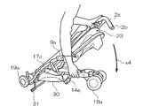
次に、図17に示すように、利用者は、把持部2a,2bのいずれかを持って、把持部2a,2bを前輪部18a,18bの方向に回動するように移動させる。
つまり、利用者は、把持部2a,2bを図の矢印x4の向きに移動させ、把持部2a,2bを前輪部18a,18bの方向に近づけるようにする。このようにして、折畳式ベビーカー1は、コンパクトに収容できるようになる。また、本実施の形態では、把持部2a,2bを持って、把持部2a,2bを前輪部18a,18bの方向に回動させたが、逆に、前輪軸部14a,14bを持って、把持部2a,2bに近づけるようにして折畳んでも同様である。
さらに、利用者が、図2に示される移動用帯部51を持って、移動用帯部51を把持部2a,2bに近づけるように引き上げて折畳むことも可能である。この方法によれば、利用者はしゃがむことなく、折畳式ベビーカー1を折畳むことができるので、利用者が背の高い場合や、荷物を抱えているとき等には便利である。
そして、この時、自立スタンド部31は、左右の後輪部19a,19bと同じ平面で、折畳まれた折畳式ベビーカー1を支えて自立して収納ができるように下降するようになっている。つまり、本実施の形態の折畳式ベビーカー1は、一対の後輪部19a,19bと自立スタンド部31によって、折畳式ベビーカー1の重量を支えて、自立させて収容できるようになっている。
このように、本実施の折畳式ベビーカー1は、折畳んでコンパクトに収容でき、かつ、自立して収容することも可能である。
また、本実施の折畳式ベビーカー1は、折畳んだ状態では、把持部2a,2bがちょうど傘の柄のような形状であるので、アンブレラタイプと称したり、コンパクトで、軽量であり、持ち運びが便利で、収容するスペースが省スペースで良いので、バギータイプのベビーカーとも称する場合がある。
Next, as shown in FIG. 17, the user holds either of the
That is, the user moves the
Further, the user can hold the moving
At this time, the self-supporting
Thus, the folding stroller 1 of the present embodiment can be folded and accommodated in a compact manner, and can also be accommodated independently.
Further, the folding stroller 1 of the present embodiment is called an umbrella type or compact, lightweight, and portable because the
本発明は、上述の実施の形態に限定されない。 The present invention is not limited to the above-described embodiment.
1・・・折畳式ベビーカー、2a,2b・・・把持部、3・・・背もたれクッション部、4a,4b・・・支持部肩帯第1挿通孔、5・・・後頭部保護クッション部、6・・・側頭部保護クッション部、7・・・頭部保護クッション部、8a,8b・・・肩帯部、9a,9b・・・側面飛出し防止部、10a,10b・・・側面軸部、11・・・横臀部保護部、12・・・座面部、13・・・座席支持部、14a,14b・・・前輪軸部、15・・・底面幅支持部、16・・・足乗せ部、17a、17b・・・後輪軸部、18a,18b・・・前輪部、19a,19b・・・後輪部、20・・・前股帯部、20a・・・前股帯挿通部、21a,21b・・・頭部保護肩帯第1挿通孔、22・・・前倒れ防止部、23・・・幌部、24・・・第1骨組部、25・・・第2骨組部、26・・・第1幌部、27・・・第2幌部、28・・・幌幅調整部、29a,29b・・・幌着脱係止受部、30・・・物入れ部、31・・・自立スタンド部、32・・・幅保持解除レバー、33・・・横幅保持部、34a,34b・・・支持部肩帯第2挿通孔、35・・・背面幅支持部、36a,36b,36c・・・幌位置固定部、37・・・幌取り付け部、38a,38b・・・頭部保護肩帯第2挿通孔、39・・・臀部中心保護部、40・・・臀部保護クッション部、41・・・連結部、42a,42b・・・幌着脱部、43・・・幌着脱固定部、44・・・背もたれ支持部、45・・・座席部、46a,46b・・・腰帯部、47・・・弾力性座席部、48・・・座面支持部、49・・・着脱連結部、64a,64b・・・クッション部肩帯第1挿通孔、65a,65b・・・クッション部肩帯第2挿通孔
DESCRIPTION OF SYMBOLS 1 ... Folding stroller, 2a, 2b ... Grasping part, 3 ... Back cushion part, 4a, 4b ... Support part shoulder belt 1st insertion hole, 5 ... Back head protection cushion part, 6 ... side head protection cushion part, 7 ... head protection cushion part, 8a, 8b ... shoulder band part, 9a, 9b ... side jump-out prevention part, 10a, 10b ... side face Shaft part, 11 ... Recumbent part protection part, 12 ... Seat surface part, 13 ... Seat support part, 14a, 14b ... Front wheel shaft part, 15 ... Bottom width support part, 16 ... Foot rest, 17a, 17b ... rear wheel shaft, 18a, 18b ... front wheel, 19a, 19b ... rear wheel, 20 ... front crotch, 20a ... front crotch insertion Part, 21a, 21b ... head protection shoulder belt first insertion hole, 22 ... forward fall prevention part, 23 ... top part, 24 ... first Frame part, 25 ... second frame part, 26 ... first hood part, 27 ... second hood part, 28 ... hood width adjustment part, 29a, 29b ...
Claims (5)
前記乳幼児が乗車した際に背面から左右の肩部分を規制する一対の肩帯部と、
前記座席部を支持する骨組部と、
一対の前輪部と一対の後輪部とを有する回動可能な車輪部と、
利用者が操作するための一対の把持部と、を備えており、
前記座席部は、前記乳幼児が着座する衝撃緩和性を有する着脱可能な弾力性座席部と、前記弾力性座席部を支持する座席支持部と、を有し、
前記弾力性座席部は、少なくとも、前記乳幼児の頭部部分を保護する頭部防護弾力性部と、前記乳幼児の臀部部分を保護する臀部防護弾力性部と、を有しており、
前記座席支持部は、前記頭部防護弾力性部が配置され、前記乳幼児が着座した際に前記乳幼児の背中側が支持される背面座席支持部と、前記臀部防護弾力性部が配置され、前記乳幼児が着座した際に前記乳幼児の臀部側が支持される臀部座席支持部と、を有し、
前記骨組部は、
一対の前記把持部からそれぞれ伸びて、前記背面座席支持部を主に支持する一対の側面軸部と、
前記前輪部を支持する一対の前輪軸部と、前記後輪部を支持する一対の後輪軸部と、
一対の前記前輪軸部の幅と一対の前記後輪軸部の幅とを使用時には前記臀部座席支持部の幅で保持し、折畳み時には一対の前記前輪軸部の幅と一対の前記後輪軸部の幅とを狭める方向の状態で保持される底面配置骨組部と、
一対の前記側面軸部と一対の後輪軸部とを使用時には前記背面座席支持部の幅で保持して、折畳み時には一対の前記側面軸部の幅と一対の後輪軸部の幅とを狭める状態で保持される背面配置骨組部と、を有しており、
一対の前記肩帯部は、前記背面座席支持部に設けられた複数対の肩帯孔と、前記頭部防護弾力性部に設けられた複数対の肩帯高さ調節孔と、により、前記乳幼児の体型に合わせて調整可能とされており、
前記頭部防護弾力性部は、一対の前記肩帯部の調整に併せて前記臀部座席支持部に対する高さの相対的位置調節が可能とされていること、
を特徴とする折畳式ベビーカー。 A seat where an infant rides;
A pair of shoulder bands for regulating the left and right shoulders from the back when the infant gets on board,
A skeleton part that supports the seat part;
A rotatable wheel portion having a pair of front wheel portions and a pair of rear wheel portions;
A pair of grips for the user to operate,
The seat portion has a removable elastic seat portion having impact relaxation properties on which the infant is seated, and a seat support portion that supports the elastic seat portion,
The elastic seat portion includes at least a head protection elastic portion that protects the head portion of the infant and a buttocks protection elastic portion that protects the buttocks portion of the infant,
The seat support elastic part is provided with the head protection elastic part, and when the infant is seated, a back seat support part that supports a back side of the infant and the buttocks protection elastic part is arranged, and the infant And a buttocks seat support portion that supports the buttocks side of the infant when seated,
The skeleton part is
A pair of side shafts extending mainly from the pair of gripping portions and mainly supporting the back seat support portion;
A pair of front wheel shaft portions that support the front wheel portion; and a pair of rear wheel shaft portions that support the rear wheel portion;
The width of the pair of front wheel shaft portions and the width of the pair of rear wheel shaft portions are held by the width of the buttocks seat support portion when used, and when folded, the width of the pair of front wheel shaft portions and the pair of rear wheel shaft portions A bottom surface arrangement frame portion held in a state of narrowing the width;
The pair of side shaft portions and the pair of rear wheel shaft portions are held by the width of the back seat support portion when used, and when folded, the pair of side shaft portions and the pair of rear wheel shaft portions are narrowed. And a back-arranged skeleton part held by
The pair of shoulder belt portions includes a plurality of pairs of shoulder belt holes provided in the back seat support portion and a plurality of pairs of shoulder belt height adjustment holes provided in the head protection elastic portion. It can be adjusted according to the baby's body shape,
The head protection elastic part is capable of adjusting the relative position of the height with respect to the buttocks seat support part in conjunction with the adjustment of the pair of shoulder bands.
A foldable baby stroller.
前記背もたれ弾力性部は、前記背面座席支持部の複数対の前記肩帯孔と対応する位置に設けられた複数対の肩帯通孔を有しており、複数対の前記肩帯孔と複数対の前記肩帯通孔とに一対の前記肩帯部が通され、複数対の前記肩帯高さ調節孔とにより、一対の前記肩帯部は調節可能とされていることを特徴とする請求項1に記載の折畳式ベビーカー。 The elastic seat portion is disposed between the back seat support portion and the head protection elastic portion, and a back elastic portion that elastically supports the back side of the seated infant, and the buttocks seat A seat surface elastic part that is disposed between a support part and the buttocks protective elastic part and elastically supports the buttocks side of the seated infant;
The backrest elastic part has a plurality of pairs of shoulder band holes provided at positions corresponding to the plurality of pairs of shoulder band holes of the back seat support part. A pair of the shoulder belt portions are passed through the pair of shoulder belt passage holes, and the pair of shoulder belt portions are adjustable by a plurality of pairs of the shoulder belt height adjustment holes. The folding stroller according to claim 1.
前記日除け部は、少なくとも2本の略逆U字状骨部と、前記略逆U字状骨部の間に張られる第一覆い部と、一対の前記把持部の近傍で取り付けられ、前記略逆U字状骨部と前記背もたれ弾力性部の上縁部付近との間を覆う第二覆い部と、を有し、前記飛出防止部の前記日除け部の取り付け位置で回動可能とされ、少なくとも前記日除け部の前記第二覆い部が折畳まれ、前記第一覆い部が広げられた状態で保持される位置を含む多段階の保持位置を有していること、を特徴とする請求項1乃至請求項3のいずれかに記載の折畳式ベビーカー。 It has a sunshade part that can be detachably attached to the vicinity of the pair of gripping parts and the pair of jump-out prevention parts,
The sunshade is attached in the vicinity of at least two substantially inverted U-shaped bone parts, a first covering part stretched between the substantially inverted U-shaped bone parts, and a pair of the gripping parts, A second cover portion covering between the inverted U-shaped bone portion and the vicinity of the upper edge portion of the backrest elastic portion, and is rotatable at an attachment position of the sunshade portion of the pop-out preventing portion. The at least one second cover part of the sunshade part is folded and has a multi-stage holding position including a position where the first cover part is held in an unfolded state. The foldable baby stroller according to any one of claims 1 to 3.
前記後輪軸部の前記後輪部が設けられている端部は、前記前輪部と離間する方向に向いており、前記後輪軸部は側面視で緩やかな略S字状カーブを有する形状となっていること、を特徴とする請求項1乃至請求項4のいずれかに記載の折畳式ベビーカー。 The rear wheel shaft part is continuously provided so as to support the front wheel shaft part provided on the extension of the side shaft part and the side shaft part from the rear,
An end portion of the rear wheel shaft portion where the rear wheel portion is provided faces in a direction away from the front wheel portion, and the rear wheel shaft portion has a shape having a gentle S-shaped curve in a side view. The foldable baby stroller according to any one of claims 1 to 4, wherein the foldable baby stroller is provided.
Priority Applications (3)
| Application Number | Priority Date | Filing Date | Title |
|---|---|---|---|
| JP2008176106A JP5121604B2 (en) | 2008-07-04 | 2008-07-04 | Folding stroller |
| CN 200910139854 CN101618732B (en) | 2008-07-04 | 2009-07-03 | Collapsible pushchair |
| HK10106542.8A HK1139904A1 (en) | 2008-07-04 | 2010-07-06 | Folding baby carriage |
Applications Claiming Priority (1)
| Application Number | Priority Date | Filing Date | Title |
|---|---|---|---|
| JP2008176106A JP5121604B2 (en) | 2008-07-04 | 2008-07-04 | Folding stroller |
Publications (2)
| Publication Number | Publication Date |
|---|---|
| JP2010013008A JP2010013008A (en) | 2010-01-21 |
| JP5121604B2 true JP5121604B2 (en) | 2013-01-16 |
Family
ID=41512177
Family Applications (1)
| Application Number | Title | Priority Date | Filing Date |
|---|---|---|---|
| JP2008176106A Active JP5121604B2 (en) | 2008-07-04 | 2008-07-04 | Folding stroller |
Country Status (3)
| Country | Link |
|---|---|
| JP (1) | JP5121604B2 (en) |
| CN (1) | CN101618732B (en) |
| HK (1) | HK1139904A1 (en) |
Families Citing this family (6)
| Publication number | Priority date | Publication date | Assignee | Title |
|---|---|---|---|---|
| JP5410313B2 (en) * | 2010-01-22 | 2014-02-05 | コンビ株式会社 | Folding stroller |
| JP5432787B2 (en) * | 2010-03-23 | 2014-03-05 | アップリカ・チルドレンズプロダクツ株式会社 | Folding baby carriage |
| JP5489834B2 (en) * | 2010-04-16 | 2014-05-14 | アップリカ・チルドレンズプロダクツ株式会社 | Folding baby carriage |
| CN106954968A (en) * | 2017-04-24 | 2017-07-18 | 浙江陀曼精密机械有限公司 | A kind of seat with eye light adjusting device |
| CN107264600A (en) * | 2017-06-01 | 2017-10-20 | 好孩子儿童用品有限公司 | A kind of children trolley |
| JP7364490B2 (en) * | 2020-02-10 | 2023-10-18 | ニューウェルブランズ・ジャパン合同会社 | Removable footrest and pram |
Family Cites Families (10)
| Publication number | Priority date | Publication date | Assignee | Title |
|---|---|---|---|---|
| JPS5583665A (en) * | 1978-12-16 | 1980-06-24 | Kasai Kk | Collapsible baby carriage |
| JPS6130939Y2 (en) * | 1980-11-13 | 1986-09-09 | ||
| JPS5954325U (en) * | 1982-10-04 | 1984-04-10 | タカタ株式会社 | Child protection sheet |
| US6679552B1 (en) * | 1999-10-27 | 2004-01-20 | Aprica Kassai Kabushikikaisha | Nursery instrument |
| JP4361303B2 (en) * | 2003-03-28 | 2009-11-11 | 株式会社ティーレックス | Baby carriage top |
| CN2619854Y (en) * | 2003-04-18 | 2004-06-09 | 周伟中 | Dual-purpose carriage for child |
| US7188897B2 (en) * | 2005-03-15 | 2007-03-13 | Graco Children's Products Inc. | Infant carrier with adjustable harness system |
| JP4757567B2 (en) * | 2005-05-27 | 2011-08-24 | コンビ株式会社 | stroller |
| JP4823592B2 (en) * | 2005-07-12 | 2011-11-24 | コンビ株式会社 | Stroller cushion |
| US8186368B2 (en) * | 2008-03-20 | 2012-05-29 | Kolcraft Enterprises, Inc. | Child caretaking structures with adjustable canopies and/or headrests |
-
2008
- 2008-07-04 JP JP2008176106A patent/JP5121604B2/en active Active
-
2009
- 2009-07-03 CN CN 200910139854 patent/CN101618732B/en active Active
-
2010
- 2010-07-06 HK HK10106542.8A patent/HK1139904A1/en unknown
Also Published As
| Publication number | Publication date |
|---|---|
| HK1139904A1 (en) | 2010-09-30 |
| CN101618732A (en) | 2010-01-06 |
| CN101618732B (en) | 2013-06-05 |
| JP2010013008A (en) | 2010-01-21 |
Similar Documents
| Publication | Publication Date | Title |
|---|---|---|
| US11684175B2 (en) | Adjustable child carrier with multiple carry orientations | |
| JP6763891B2 (en) | Baby carrier | |
| US8650663B2 (en) | Bunting bag with cover | |
| US9357852B2 (en) | Infant carrier with expandable seat | |
| US6836902B2 (en) | Infant walking trainer and carrier garment | |
| US20140231472A1 (en) | Strap-on child carrier with support seating element | |
| US20080313812A1 (en) | Portable Infant Support Apparatus | |
| US20100072236A1 (en) | Multifunctional child carrier | |
| JP5121604B2 (en) | Folding stroller | |
| EP2194818B1 (en) | Arrangement for adjusting the height of a carrier | |
| US20110240693A1 (en) | Baby carrier with tie straps | |
| WO2018140570A1 (en) | Child carrier with base width adjustment rail | |
| US20100051658A1 (en) | Infant sling | |
| US20160128491A1 (en) | A combination of child carrier and stroller | |
| EP2755527A1 (en) | Child carrier | |
| US20100155446A1 (en) | Device for Carrying a Child | |
| US8484782B2 (en) | Infant bonding lap seat | |
| WO2012079787A1 (en) | Child carrier | |
| KR200473475Y1 (en) | Baby hip seat carrier | |
| NL2008730C2 (en) | Child carrier. | |
| US9474307B2 (en) | Pants to assist in holding up a diaper | |
| KR20150004498U (en) | Variable width multi-functional sling blanket | |
| US20120272926A1 (en) | Shopping cart and walking harness | |
| GB2442533A (en) | Supportive insert for a pushchair | |
| JP2007195937A (en) | Sling type baby holding carrier |
Legal Events
| Date | Code | Title | Description |
|---|---|---|---|
| A621 | Written request for application examination |
Free format text: JAPANESE INTERMEDIATE CODE: A621 Effective date: 20110701 |
|
| TRDD | Decision of grant or rejection written | ||
| A977 | Report on retrieval |
Free format text: JAPANESE INTERMEDIATE CODE: A971007 Effective date: 20121011 |
|
| A01 | Written decision to grant a patent or to grant a registration (utility model) |
Free format text: JAPANESE INTERMEDIATE CODE: A01 Effective date: 20121016 |
|
| A01 | Written decision to grant a patent or to grant a registration (utility model) |
Free format text: JAPANESE INTERMEDIATE CODE: A01 |
|
| A61 | First payment of annual fees (during grant procedure) |
Free format text: JAPANESE INTERMEDIATE CODE: A61 Effective date: 20121023 |
|
| FPAY | Renewal fee payment (event date is renewal date of database) |
Free format text: PAYMENT UNTIL: 20151102 Year of fee payment: 3 |
|
| R150 | Certificate of patent or registration of utility model |
Free format text: JAPANESE INTERMEDIATE CODE: R150 Ref document number: 5121604 Country of ref document: JP Free format text: JAPANESE INTERMEDIATE CODE: R150 |
|
| R250 | Receipt of annual fees |
Free format text: JAPANESE INTERMEDIATE CODE: R250 |
|
| R250 | Receipt of annual fees |
Free format text: JAPANESE INTERMEDIATE CODE: R250 |
|
| R250 | Receipt of annual fees |
Free format text: JAPANESE INTERMEDIATE CODE: R250 |
|
| R250 | Receipt of annual fees |
Free format text: JAPANESE INTERMEDIATE CODE: R250 |
|
| R250 | Receipt of annual fees |
Free format text: JAPANESE INTERMEDIATE CODE: R250 |
|
| R250 | Receipt of annual fees |
Free format text: JAPANESE INTERMEDIATE CODE: R250 |
|
| R250 | Receipt of annual fees |
Free format text: JAPANESE INTERMEDIATE CODE: R250 |
|
| R250 | Receipt of annual fees |
Free format text: JAPANESE INTERMEDIATE CODE: R250 |
|
| R250 | Receipt of annual fees |
Free format text: JAPANESE INTERMEDIATE CODE: R250 |