JP5121253B2 - Powder filling apparatus, powder filling method and process cartridge - Google Patents
Powder filling apparatus, powder filling method and process cartridge Download PDFInfo
- Publication number
- JP5121253B2 JP5121253B2 JP2007048405A JP2007048405A JP5121253B2 JP 5121253 B2 JP5121253 B2 JP 5121253B2 JP 2007048405 A JP2007048405 A JP 2007048405A JP 2007048405 A JP2007048405 A JP 2007048405A JP 5121253 B2 JP5121253 B2 JP 5121253B2
- Authority
- JP
- Japan
- Prior art keywords
- powder
- filling
- container
- filled
- pressure hopper
- Prior art date
- Legal status (The legal status is an assumption and is not a legal conclusion. Google has not performed a legal analysis and makes no representation as to the accuracy of the status listed.)
- Expired - Fee Related
Links
Images


Description
本発明は、静電式複写機、プリンタ等の画像形成装置の現像装置に用いられるトナー等の微粉体を、被充填容器に充填する粉体充填装置、粉体充填方法、及び、該粉体充填方法で粉体の充填が行われたプロセスカートリッジに関する。 The present invention relates to a powder filling apparatus, a powder filling method, and the powder for filling a container to be filled with fine powder such as toner used in a developing device of an image forming apparatus such as an electrostatic copying machine or a printer. The present invention relates to a process cartridge in which powder is filled by a filling method.
従来、トナー等の微粉体は、スクリューフィーダー、オーガー式充填機、粉体自身の重力による自由落下、若しくは、空気を用いて粉体を搬送する手段等により粉体を被粉体充填容器に充填している。例えば、特許文献1には、空気を用いて粉体を搬送する方法の一例が記載されている。 Conventionally, fine powder such as toner is filled into a powder-filled container by a screw feeder, an auger-type filling machine, free fall of the powder itself due to gravity, or means for conveying the powder using air. doing. For example, Patent Document 1 describes an example of a method for conveying powder using air.
特許文献1には、粉体供給機に貯留した粉体に気体を導入して粉体の流動性を高めた後、導入した気体の圧力を利用し粉体を被充填容器へ充填する構成が開示されている。特許文献1では、導入した圧力により粉体供給機中の粉体を搬送チューブへと搬送し、その搬送チューブを介して被充填容器へと粉体を供給し、所望の充填量に達した後、粉体供給機中の圧力を開放することで粉体の搬送を停止している。 Patent Document 1 discloses a configuration in which gas is introduced into powder stored in a powder supply machine to improve the fluidity of the powder, and then the powder is filled into the filling container using the pressure of the introduced gas. It is disclosed. In Patent Document 1, after the powder in the powder feeder is transported to the transport tube by the introduced pressure, the powder is supplied to the container to be filled through the transport tube, and the desired filling amount is reached. The powder conveyance is stopped by releasing the pressure in the powder feeder.
しかしながら、特許文献1に開示されている構成においては、気体で粉体供給機中に貯留している粉体の流動性を高めた後に被充填容器へと粉体を充填しているため、粉体を必要以上に流動化してしまい、粉体を高密度に被充填容器に充填することが困難であった。また、更には必要以上に流動化することで、充填に長時間を要するようになっていた。 However, in the configuration disclosed in Patent Document 1, the powder is filled into the container to be filled after increasing the fluidity of the powder stored in the powder supply machine with gas. The body was fluidized more than necessary, and it was difficult to fill the filled container with powder at a high density. Furthermore, the fluidization more than necessary required a long time for filling.
また、特許文献2では、粉体の流動性を高めることなく気体で搬送する充填方法が提案されている。 特許文献2においては、先ず測定チャンバを減圧状態にすることで、粉体を測定チャンバに定量充填し、その後、測定チャンバの粉体搬送方向上流側から圧力を導入し、その圧力導入により粉体を充填する方法が開示されている。
Further,
しかしながら、特許文献2に開示されている構成においては、測定チャンバの大きさにより粉体充填量が決まってしまうため、例えば、充填量の異なる充填を同じ装置で行う場合、測定チャンバ自体を交換することとなり、その負荷は大きいものとなる。また、多量の粉体を充填する際、本構成では、減圧により測定チャンバに充填する段階で、充填する粉体でフィルターが詰まりやすく、所定量の充填が困難になりやすいものであった。
However, in the configuration disclosed in
また、特許文献3及び特許文献4には、粉体に含まれる気体を脱気することで粉体を高密度にした後に被充填容器に充填する構成が開示されている。
Patent Document 3 and
すなわち、特許文献3においては、内室及び外室を持つ中空円筒形の容器に粉体を充填し、その後、内室に設けた孔から粉体に含まれる空気を抜き、粉体を締固めた後に粉体を下方のフレキシブルな被充填容器に充填する構成が開示されている。 That is, in Patent Document 3, a hollow cylindrical container having an inner chamber and an outer chamber is filled with powder, and then air contained in the powder is discharged from a hole provided in the inner chamber, and the powder is compacted. After that, a configuration is disclosed in which the powder is filled into a flexible container to be filled below.
また、特許文献4においては、同様のフィルター機能を有する粉体充填室へ横型オーガスクリューを用いて粉体を充填し、充填と共に脱気を行い粉体を高密度にし、その後、被充填容器へと粉体を充填する構成が開示されている。
In
更に、被充填容器へ粉体を高密度に充填する方法として、以下の技術も開示されている。
特許文献5には、粉体充填装置の充填ノズルが、充填容器内の粉体によって囲繞された状態で粉体を充填することにより、粉体の飛散を避けつつ、容器底部から徐々に上側に空気を追い出す方法であり、特に充填容器が細く狭い形状である場合には有効な方法が開示されている。
また、特許文献6には,粉体充填装置のエア吸引管を予め容器内部へ挿入した状態から、粉体の充填量にともなってエア吸引管を上昇させながら粉体を充填することにより、粉体内の気体を吸引し、粉体を高密度かつ高速に被充填容器へ充填する方法が開示されている。
Furthermore, the following technique is also disclosed as a method for filling a container to be filled with powder with high density.
In Patent Document 5, the filling nozzle of the powder filling device fills the powder in a state surrounded by the powder in the filling container, so that the powder is gradually scattered upward from the bottom of the container while avoiding scattering of the powder. It is a method for expelling air, and an effective method is disclosed particularly when the filling container has a narrow and narrow shape.
In
本発明の目的は、粉体を高密度に充填することができる粉体充填装置及び粉体充填方法を提供することにある。
また、本発明の目的は、粉体を短時間で充填することができる粉体充填装置及び粉体充填方法を提供することにある。
更に、本発明の目的は、上記の粉体充填方法によって現像剤の充填を行った電子写真用プロセスカートリッジを提供することにある。
An object of the present invention is to provide a powder filling apparatus and a powder filling method capable of filling powder with high density.
Another object of the present invention is to provide a powder filling apparatus and a powder filling method capable of filling powder in a short time.
Another object of the present invention is to provide an electrophotographic process cartridge filled with a developer by the above powder filling method.
即ち、本発明は、加圧ホッパを有する粉体充填装置であって、前記加圧ホッパが、粉体を排出する排出部と、少なくとも前記加圧ホッパ内の粉体により形成される粉体層表面よりも上方に位置する気体導入部とを有しており、前記粉体層は加圧ホッパ内において前記排出部を塞ぐように形成されるものであり、前記排出部を閉じた状態で、前記気体導入部より気体を導入して、前記加圧ホッパ内を加圧し、加圧後、前記排出部を開放することにより、圧力を利用して、前記排出部を塞ぐように形成されている粉体層を排出し、粉体を被充填容器に充填することを特徴とする粉体充填装置に関する。 That is, the present invention is a powder filling apparatus having a pressure hopper, in which the pressure hopper discharges a powder, and a powder layer formed by at least the powder in the pressure hopper A gas introduction part located above the surface, the powder layer is formed so as to close the discharge part in the pressure hopper, and the discharge part is closed, Gas is introduced from the gas introduction part, the inside of the pressurization hopper is pressurized, and after the pressurization, the discharge part is opened, so that the discharge part is closed using pressure. The present invention relates to a powder filling apparatus characterized by discharging a powder layer and filling powder into a filling container.
また、本発明は、加圧ホッパを有する粉体充填装置を用いて行う粉体充填方法であって、前記加圧ホッパが、粉体を排出する排出部と、少なくとも前記加圧ホッパ内の粉体により形成される粉体層表面よりも上方に位置する気体導入部とを有しており、前記粉体層は加圧ホッパ内において前記排出部を塞ぐように形成し、前記排出部を閉じた状態で、前記気体導入部より気体を導入して、前記加圧ホッパ内を加圧し、加圧後、前記排出部を開放することにより、圧力を利用して、前記排出部を塞ぐように形成されている粉体層を排出し、粉体を被充填容器に充填することを特徴とする粉体充填方法に関する。 Further, the present invention is a powder filling method performed using a powder filling apparatus having a pressure hopper, wherein the pressure hopper discharges powder, and at least the powder in the pressure hopper A gas introduction part located above the surface of the powder layer formed by the body, the powder layer is formed so as to close the discharge part in the pressure hopper, and the discharge part is closed In such a state, gas is introduced from the gas introduction part, the inside of the pressure hopper is pressurized, and after the pressurization, the discharge part is opened to close the discharge part using pressure. The present invention relates to a powder filling method characterized by discharging a formed powder layer and filling a filled container with powder.
更に、本発明は、蓋と粉体収納部に分かれた被充填容器に粉体を充填する粉体充填方法であって、被充填容器内に粉体を送り込む排出部の後端部が、粉体収納部に充填された粉体の表面形状として求められる形状と実質的に等しい形状を有しており、粉体収納部における粉体の表面形状を求められる形状に成形して充填を行うことを特徴とする粉体充填方法に関する。 Further, the present invention is a powder filling method for filling powder into a filling container divided into a lid and a powder container, wherein the rear end of the discharge part for feeding the powder into the filling container is a powder. It has a shape that is substantially equal to the shape required as the surface shape of the powder filled in the body storage part, and the surface shape of the powder in the powder storage part is molded into the required shape for filling. The present invention relates to a powder filling method.
更に、本発明は、蓋と粉体収納部に分かれた被充填容器に粉体を充填する粉体充填方法であって、被充填容器内に粉体を送り込む排出部の後端部が、被充填容器の蓋の内面側形状と実質的に等しい形状を有しており、粉体収納部における粉体の表面形状を該蓋の内面側形状と実質的に等しい形状に成形して充填を行うことを特徴とする粉体充填方法に関する。 Furthermore, the present invention is a powder filling method for filling powder into a container to be filled divided into a lid and a powder container, wherein the rear end of the discharge part for feeding the powder into the container to be filled is covered. It has a shape that is substantially equal to the shape of the inner surface of the lid of the filling container, and is filled by forming the surface shape of the powder in the powder container into a shape that is substantially equal to the shape of the inner surface of the lid. The present invention relates to a powder filling method.
更に、本発明は、上記の粉体充填方法によって現像剤の充填を行った電子写真用プロセスカートリッジに関する。 The present invention further relates to an electrophotographic process cartridge filled with a developer by the above-described powder filling method.
本発明の充填装置並びに充填方法を用いることで、高密度な充填を短時間で行うことができる。 By using the filling apparatus and the filling method of the present invention, high-density filling can be performed in a short time.
以下、本発明について説明する。
第1の発明は、加圧ホッパを有する粉体充填装置であって、前記加圧ホッパが、粉体を排出する排出部と、少なくとも前記加圧ホッパ内の粉体により形成される粉体層表面よりも上方に位置する気体導入部とを有しており、前記粉体層は加圧ホッパ内において前記排出部を塞ぐように形成されるものであり、前記排出部を閉じた状態で、前記気体導入部より気体を導入して、前記加圧ホッパ内を加圧し、加圧後、前記排出部を開放することにより、圧力を利用して、前記排出部を塞ぐように形成されている粉体層を排出し、粉体を被充填容器に充填することを特徴とする粉体充填装置に関する。
第1の発明の粉体充填装置では、排出部を閉じた状態で加圧することにより粉体を圧縮し、その後、排出部を開放することによって、密度が高められた粉体が排出されるため、被充填容器へのより高密度な充填を容易に行うことができる。
The present invention will be described below.
1st invention is a powder filling apparatus which has a pressure hopper, Comprising: The said pressure hopper discharges | emits the powder, The powder layer formed with the powder in the said pressure hopper at least A gas introduction part located above the surface, the powder layer is formed so as to close the discharge part in the pressure hopper, and the discharge part is closed, Gas is introduced from the gas introduction part, the inside of the pressurization hopper is pressurized, and after the pressurization, the discharge part is opened, so that the discharge part is closed using pressure. The present invention relates to a powder filling apparatus characterized by discharging a powder layer and filling powder into a filling container.
In the powder filling device according to the first aspect of the invention, the powder is compressed by pressurizing the discharge part in a closed state, and then the powder having an increased density is discharged by opening the discharge part. Thus, it is possible to easily fill the filled container with a higher density.
また、第2の発明は、第1の発明に示した粉体充填装置において、前記加圧ホッパと前記粉体層が接する部分の少なくとも一部に、空気を通し粉体を遮断するフィルターが設けており、前記フィルターを介して、加圧ホッパ内の粉体層中に含まれる気体を脱気することを特徴とする。
第2の発明の粉体充填装置を用いることで、前記粉体を更に高密度に充填することができる。
According to a second aspect of the present invention, in the powder filling apparatus according to the first aspect of the present invention, a filter that blocks air through air is provided in at least a part of a portion where the pressure hopper contacts the powder layer. The gas contained in the powder layer in the pressure hopper is degassed through the filter.
By using the powder filling apparatus of the second invention, the powder can be filled at a higher density.
更に、第3の発明は、第1の発明に示した粉体充填装置において、前記加圧ホッパに連通し、加圧可能な空間の容積を大きくするための補助容器が設けられていることを特徴とする。
第3の発明の粉体充填装置を用いることで、種々の充填量に対応できるようになり、装置の汎用性を向上できる。
Furthermore, a third aspect of the invention is that in the powder filling apparatus shown in the first aspect of the invention, an auxiliary container is provided for increasing the volume of the pressurizable space that communicates with the pressure hopper. Features.
By using the powder filling apparatus of the third invention, it becomes possible to cope with various filling amounts, and the versatility of the apparatus can be improved.
更に、第4の発明は、第3の発明に示した粉体充填装置において、前記加圧ホッパと前記補助容器との間に、空気を通し粉体を遮断するフィルターを設けたことを特徴とする。
第4の発明の粉体充填装置を用いることで、前記補助容器に前記粉体が入り込んでしまうことを防ぐことができる。
Further, a fourth invention is characterized in that, in the powder filling apparatus shown in the third invention, a filter is provided between the pressurizing hopper and the auxiliary container so as to pass air and block the powder. To do.
By using the powder filling apparatus of the fourth invention, it is possible to prevent the powder from entering the auxiliary container.
更に、第5の発明は、第3の発明に示した粉体充填装置において、前記補助容器が、前記粉体層の表面よりも上方で前記加圧ホッパと接続されていることを特徴とする。
第5の発明の粉体充填装置を用いることで、前記補助容器内の加圧エアーを効率良く前記粉体の搬送に用いることができる。
Furthermore, a fifth invention is characterized in that, in the powder filling apparatus shown in the third invention, the auxiliary container is connected to the pressure hopper above the surface of the powder layer. .
By using the powder filling apparatus according to the fifth aspect of the invention, the pressurized air in the auxiliary container can be efficiently used for conveying the powder.
更に、第6の発明は、第1の発明に示した粉体充填装置において、前記被充填容器に充填された粉体の充填量を検知する検知手段と、該検知手段によって検知される充填量が所定量になった際、一旦前記加圧ホッパからの粉体の排出を停止し、停止した後、再び充填を行う制御手段とを有することを特徴とする。
第6の発明の粉体充填装置では、一旦加圧ホッパからの粉体の排出を停め、粉体を落ち着かせてから再充填を行うことで、前記被充填容器への粉体の充填量の制御精度を向上させることができる。
Further, the sixth invention is the powder filling apparatus shown in the first invention, wherein the detecting means for detecting the filling amount of the powder filled in the filling container, and the filling amount detected by the detecting means. And control means for once again stopping the discharge of the powder from the pressure hopper when it reaches a predetermined amount, and then filling again.
In the powder filling apparatus according to the sixth aspect of the present invention, the discharge of the powder from the pressure hopper is temporarily stopped, and the powder is settled after the powder is settled, so that the filling amount of the powder into the container to be filled is reduced. Control accuracy can be improved.
更に、第7の発明は、第6の発明に示した粉体充填装置において、前記検知手段が、前記加圧ホッパの質量の減少を検知することで、前記被充填容器の粉体の充填量を検知することを特徴とする。
第7の発明の粉体充填装置を用いることで、粉体充填装置の汎用性を向上させ、更に粉体の充填量の制御精度を向上させることができる。
Furthermore, a seventh aspect of the present invention is the powder filling apparatus according to the sixth aspect, wherein the detecting means detects a decrease in the mass of the pressure hopper so that the filling amount of the powder in the container to be filled is detected. It is characterized by detecting.
By using the powder filling device of the seventh invention, the versatility of the powder filling device can be improved, and the control accuracy of the powder filling amount can be further improved.
更に、第8の発明は、第1の発明に示した粉体充填装置において、被充填容器内に粉体を送り込む排出部の後端部が、被充填容器内に充填された粉体の表面形状として求められる形状と実質的に等しい形状を有することを特徴とする。
尚、以降の発明においても同じであるが、排出部の後端部とは、加圧ホッパの排出部そのものの後端部であっても良く、或いは、加圧ホッパの排出部に連結されたチューブの如き搬送路の後端部であっても良い。さらには、後端部とは、排出部或いは搬送路に接続された脱気装置の如き部材を指す場合も含む。また、後端部とは、粉体の排出方向の下流側の端部のことである。
第8の発明の粉体充填装置を用いることで、前記粉体の充填量を更に増やし、蓋をする場合等においてもトナーの飛散等を抑制することができる。
Further, the eighth invention is the powder filling apparatus shown in the first invention, wherein the rear end of the discharge part for feeding the powder into the filled container is the surface of the powder filled in the filled container It has the shape substantially equal to the shape calculated | required as a shape, It is characterized by the above-mentioned.
The same applies to the following inventions, but the rear end portion of the discharge portion may be the rear end portion of the discharge portion of the pressure hopper itself, or connected to the discharge portion of the pressure hopper. It may be the rear end portion of the conveyance path such as a tube. Furthermore, the rear end portion includes a case where a member such as a deaeration device connected to the discharge portion or the conveyance path is included. Further, the rear end portion is an end portion on the downstream side in the powder discharging direction.
By using the powder filling apparatus according to the eighth aspect of the present invention, it is possible to further increase the filling amount of the powder and to suppress toner scattering and the like even when the lid is covered.
更に、第9の発明は、第1の発明に示した粉体充填装置において、被充填容器内に粉体を送り込む排出部の後端部が、被充填容器の蓋の内面側形状と実質的に等しい形状を有していることを特徴とする。
第9の発明の粉体充填装置を用いることで、前記粉体の充填量を更に増やすことができる。また、蓋の内面側形状と実質的に等しい形状を有している粉体層表面とすることができるため、蓋をかぶせる場合においても、蓋の凸部等によって粉体層が荒らされることがなく、接合面や周辺にトナーを飛散させたりすることなく良好な接合を行うことができる。
Further, the ninth invention is the powder filling apparatus shown in the first invention, wherein the rear end portion of the discharge portion for feeding the powder into the filled container is substantially the same as the inner surface side shape of the lid of the filled container. It has the shape equal to.
By using the powder filling apparatus according to the ninth aspect of the invention, the filling amount of the powder can be further increased. Further, since the surface of the powder layer having a shape substantially equal to the shape of the inner surface side of the lid can be obtained, even when the lid is covered, the powder layer may be roughened by the convex portion of the lid. Therefore, it is possible to perform good bonding without scattering toner on the bonding surface or the periphery.
更に、第10の発明は、第8の発明に示した粉体充填装置において、被充填容器内に粉体を送り込む排出部の後端部が、被充填容器内を脱気する脱気装置を備えていることを特徴とする。
第10の発明の粉体充填装置を用いることで、前記粉体を更に高密度に充填することができる。また、前記被充填容器の蓋を接合する際の前記粉体の飛散を防止できる。
Furthermore, a tenth aspect of the present invention is the powder filling apparatus according to the eighth aspect, wherein the rear end portion of the discharge unit that feeds the powder into the filled container degass the filled container. It is characterized by having.
By using the powder filling apparatus according to the tenth aspect of the invention, the powder can be filled at a higher density. Moreover, scattering of the powder when the lid of the container to be filled is joined can be prevented.
更に、第11の発明は、第9の発明に示した粉体充填装置において、被充填粉体への粉体の充填が、脱気装置を用いて粉体収納部内を脱気しながら行われるものであり、被充填容器内に粉体を送り込む排出部の後端部に、被充填容器の蓋の内面側形状と実質的に等しい形状を有するフィルターが付けられており、前記フィルターを介して脱気が行われることを特徴とする。
第11の発明の粉体充填装置を用いることで、前記粉体を更に高密度に充填することができる。また、前記被充填容器の蓋を接合する際の前記粉体の飛散を防止できる。
Furthermore, an eleventh aspect of the invention is the powder filling apparatus according to the ninth aspect, wherein the filling of the powder into the powder to be filled is performed while the inside of the powder container is deaerated using the deaerator. A filter having a shape substantially equal to the shape of the inner surface of the lid of the container to be filled is attached to the rear end of the discharge part for feeding the powder into the container to be filled, Degassing is performed.
By using the powder filling apparatus according to the eleventh aspect of the invention, the powder can be filled at a higher density. Moreover, scattering of the powder when the lid of the container to be filled is joined can be prevented.
更に、第12の発明は、第1の発明に示した粉体充填装置において、被充填容器内に粉体を送り込む排出部の後端部には、被充填容器と密着させるためのシール部材が備えられていることを特徴とする。
第12の発明の粉体充填装置を用いることで、充填中の前記粉体の被充填容器外への漏れを防ぐことができる。
Furthermore, a twelfth aspect of the invention is the powder filling apparatus according to the first aspect of the invention, wherein a seal member for bringing the powder into the container to be filled is in contact with the container to be filled at the rear end of the discharge part. It is provided.
By using the powder filling apparatus of the twelfth invention, leakage of the powder being filled out of the container to be filled can be prevented.
更に、第13の発明は、第1〜12のいずれか1つの発明に示した粉体充填装置において、前記加圧ホッパと前記被充填容器との間に、前記粉体を貯留する貯留部が設けられており、前記貯留部は、少なくともその壁面の一部が、空気を通し粉体を遮断する貯留部フィルターで構成されており、前記貯留部は、前記粉体を前記被充填容器へと排出する貯留部粉体排出口を封止するシャッターを有していることを特徴とする。
第13の発明の粉体充填装置を用いることで、前記粉体を被充填容器に更に高密度に充填することができる。また、前記粉体を素早く充填できる。また、高密度に充填しながら、充填による粉体への負荷を軽減できる。また、粉体による装置汚れの発生を抑制できる。
Further, a thirteenth aspect of the invention is the powder filling apparatus according to any one of the first to twelfth aspects, wherein a storage part for storing the powder is provided between the pressure hopper and the filling container. The storage unit is configured by a storage unit filter that at least part of the wall surface passes air and blocks powder, and the storage unit transfers the powder to the container to be filled. It has the shutter which seals the storage part powder discharge port discharged.
By using the powder filling apparatus according to the thirteenth aspect of the invention, the powder can be filled into the filled container at a higher density. Moreover, the powder can be quickly filled. In addition, the load on the powder due to filling can be reduced while filling with high density. Moreover, generation | occurrence | production of the apparatus dirt by powder can be suppressed.
また、第14の発明は、第13の発明に示した粉体充填装置において、前記貯留部フィルターを介して前記貯留部内を脱気する貯留部脱気装置が接続されていることを特徴とする。
第14の発明の粉体充填装置を用いることで、前記粉体を更に高密度に、且つ短時間で充填することができる。
According to a fourteenth aspect of the present invention, in the powder filling apparatus according to the thirteenth aspect of the present invention, a reservoir deaeration device for deaerating the interior of the reservoir via the reservoir filter is connected. .
By using the powder filling apparatus according to the fourteenth aspect of the invention, the powder can be filled at a higher density and in a shorter time.
更に、第15の発明は、第13の発明に示した粉体充填装置において、前記貯留部フィルターを介して前記貯留部内へ気体を導入する貯留部給気装置が接続されていることを特徴とする。
第15の発明の粉体充填装置を用いることで、前記貯留部フィルターに付着する粉体の量を減らせ、充填精度を高めることができる。また、更には、前記貯留部フィルターの寿命を延長させることができる。また、更には前記貯留部フィルターの通気性能を安定化でき、耐久後に至るまで充填精度を安定化させることができる。
Furthermore, the fifteenth invention is characterized in that, in the powder filling apparatus shown in the thirteenth invention, a reservoir air supply device for introducing gas into the reservoir via the reservoir filter is connected. To do.
By using the powder filling apparatus according to the fifteenth aspect of the invention, the amount of powder adhering to the reservoir filter can be reduced and the filling accuracy can be increased. Furthermore, the life of the reservoir filter can be extended. Furthermore, the ventilation performance of the reservoir filter can be stabilized, and the filling accuracy can be stabilized until after the endurance.
更に、第16の発明は、第13の発明に示した粉体充填装置において、前記貯留部粉体排出口の大きさが、前記被充填容器に設けられた粉体充填用の充填口よりも小さいことを特徴とする。
第16の発明の粉体充填装置を用いることで、前記貯留部から被充填容器への充填時の粉体に起因する汚れの発生を抑制することができる。
Furthermore, the sixteenth aspect of the invention is the powder filling apparatus shown in the thirteenth aspect of the invention, wherein the size of the reservoir powder discharge port is larger than the powder filling port provided in the container to be filled. It is small.
By using the powder filling apparatus according to the sixteenth aspect of the invention, it is possible to suppress the occurrence of dirt caused by the powder when filling the filling container from the reservoir.
また、第17の発明は、加圧ホッパを有する粉体充填装置を用いて行う粉体充填方法であって、前記加圧ホッパが、粉体を排出する排出部と、少なくとも前記加圧ホッパ内の粉体により形成される粉体層表面よりも上方に位置する気体導入部とを有しており、前記粉体層は加圧ホッパ内において前記排出部を塞ぐように形成し、前記排出部を閉じた状態で、前記気体導入部より気体を導入して、前記加圧ホッパ内を加圧し、加圧後、前記排出部を開放することにより、圧力を利用して、前記排出部を塞ぐように形成されている粉体層を排出し、粉体を被充填容器に充填することを特徴とする粉体充填方法に関する。
第17の発明の粉体充填方法を用いることで、より高密度に、且つ短時間で、被充填容器への粉体の充填を行うことができる。
The seventeenth invention is a powder filling method performed using a powder filling apparatus having a pressure hopper, wherein the pressure hopper includes a discharge portion for discharging powder, and at least inside the pressure hopper. A gas introduction portion positioned above the surface of the powder layer formed by the powder of the powder, and the powder layer is formed so as to close the discharge portion in a pressure hopper, and the discharge portion In a closed state, gas is introduced from the gas introduction part, the inside of the pressure hopper is pressurized, and after the pressurization, the discharge part is opened to block the discharge part using pressure. It is related with the powder filling method characterized by discharging the powder layer formed in this way and filling a filling container with the powder.
By using the powder filling method according to the seventeenth aspect of the present invention, the filling container can be filled with powder at a higher density and in a shorter time.
更に、第18の発明は、第17の発明に示した粉体充填方法において、加圧ホッパの加圧時の導入圧が、10〜150kPaであることを特徴とする。
第18の発明の粉体充填方法を用いることで、前記粉体を短時間で高密度に充填することができる。
Furthermore, an eighteenth invention is characterized in that, in the powder filling method shown in the seventeenth invention, the introduction pressure when the pressure hopper is pressurized is 10 to 150 kPa.
By using the powder filling method of the eighteenth aspect of the invention, the powder can be filled with high density in a short time.
更に、第19の発明は、第17の発明に示した粉体充填方法において、前記加圧ホッパと前記粉体層とが接する部分の少なくとも一部に、空気を通し粉体を遮断するフィルターが設けられており、前記フィルターを介して加圧ホッパ内の粉体層に含まれる気体を脱気した後、被充填容器への粉体の充填が行われることを特徴とする。
第19の発明の粉体充填方法を用いることで、前記粉体を更に高密度に充填することができる。
Further, a nineteenth aspect of the invention is the powder filling method according to the seventeenth aspect, wherein a filter that blocks air by passing air through at least a part of a portion where the pressure hopper contacts the powder layer. It is provided, and after the gas contained in the powder layer in the pressure hopper is degassed through the filter, the filling container is filled with the powder.
By using the powder filling method of the nineteenth invention, the powder can be filled at a higher density.
更に、第20の発明は、第17の発明に示した粉体充填方法において、前記加圧ホッパに連通し、加圧可能な空間の容積を大きくするための補助容器が設けられていることを特徴とする。
第20の発明の粉体充填方法を用いることで、種々の充填量に対応できる充填方法とすることができ、充填方法の汎用性を向上できる。
Furthermore, a twentieth aspect of the invention is the powder filling method according to the seventeenth aspect of the invention, wherein an auxiliary container for increasing the volume of the pressurizable space is provided in communication with the pressure hopper. Features.
By using the powder filling method of the twentieth invention, it is possible to obtain a filling method that can cope with various filling amounts, and the versatility of the filling method can be improved.
更に、第21の発明は、第20の発明に示した粉体充填方法において、前記加圧ホッパと前記補助容器との間に、空気を通し粉体を遮断する補助容器フィルターを設けたことを特徴とする。
第21の発明の粉体充填方法を用いることで、前記補助容器側に前記粉体が入り込んでしまうことを防ぐことができる。
Furthermore, the twenty-first invention is the powder filling method shown in the twentieth invention, wherein an auxiliary container filter is provided between the pressure hopper and the auxiliary container to block air through the air. Features.
By using the powder filling method according to the twenty-first aspect of the invention, it is possible to prevent the powder from entering the auxiliary container.
更に、第22の発明は、第20の発明に示した粉体充填方法において、前記補助容器が、少なくとも前記粉体層表面よりも上方で前記加圧ホッパと接続されていることを特徴とする。
第22の発明の粉体充填方法を用いることで、前記補助容器内の加圧エアーを効率良く前記粉体の搬送に用いることができる。
Furthermore, a twenty-second invention is characterized in that, in the powder filling method shown in the twentieth invention, the auxiliary container is connected to the pressure hopper at least above the surface of the powder layer. .
By using the powder filling method according to the 22nd aspect of the invention, the pressurized air in the auxiliary container can be efficiently used for conveying the powder.
更に、第23の発明は、第17の発明に示した粉体充填方法において、前記加圧ホッパからの粉体排出時、少なくとも1回は前記排出部からの粉体の排出量を減らす或いは排出を停止する工程を含むことを特徴とする。
第23の発明の粉体充填方法では、加圧ホッパからの粉体の排出を一旦停める或いは緩めて粉体を落ち着かせてから、再度充填を行うことで、前記被充填容器への粉体の充填量の制御精度を向上させることができる。
Further, the twenty-third aspect is the powder filling method according to the seventeenth aspect, wherein the amount of discharged powder from the discharge portion is reduced or discharged at least once when the powder is discharged from the pressure hopper. And a step of stopping the operation.
In the powder filling method according to the twenty-third aspect of the present invention, the discharge of the powder from the pressure hopper is temporarily stopped or loosened to settle the powder, and then the filling is performed again, whereby the powder into the container to be filled is filled. The control accuracy of the filling amount can be improved.
更に第24の発明は、第17の発明に示した粉体充填方法において、前記加圧ホッパからの粉体排出時、少なくとも1回は前記排出部からの粉体の排出を停止する工程を含み、排出停止時の1回あたりの時間が0.2秒以上であることを特徴とする。
第24の発明の粉体充填方法では、加圧ホッパからの粉体の排出を一旦停めて粉体を落ち着かせてから、再度充填を行うことで、前記被充填容器への粉体の充填量の制御精度を向上させることができる。
Furthermore, a twenty-fourth aspect of the invention is the powder filling method according to the seventeenth aspect of the invention, comprising the step of stopping the discharge of the powder from the discharge portion at least once when the powder is discharged from the pressure hopper. The time per discharge when stopping the discharge is 0.2 seconds or more.
In the powder filling method according to the twenty-fourth aspect of the invention, the amount of powder to be filled in the container to be filled is obtained by once stopping the discharge of the powder from the pressure hopper and allowing the powder to settle, and then filling again. The control accuracy can be improved.
更に、第25の発明は、第24の発明に示した粉体充填方法において、前記加圧ホッパからの排出を停止するタイミングが、前記被充填容器への最終的な充填量の70%から95%を排出した時点であることを特徴とする。
第25の発明の粉体充填方法を用いることで、前記被充填容器への粉体の充填量の精度を向上させ、且つ、短時間で充填することができる。上記のタイミングで一旦排出を停止した場合には、加圧ホッパ内の加圧度が程度であり、所望の最終的な充填量に対する微調整を行いやすい。
Furthermore, according to a 25th aspect of the invention, in the powder filling method of the 24th aspect of the invention, the timing for stopping the discharge from the pressure hopper is from 70% to 95% of the final filling amount of the filling container. % At the time of discharge.
By using the powder filling method of the twenty-fifth aspect of the invention, the accuracy of the filling amount of the powder into the filling container can be improved and the filling can be performed in a short time. When the discharge is temporarily stopped at the above timing, the degree of pressurization in the pressurization hopper is moderate, and it is easy to make a fine adjustment to a desired final filling amount.
更に、第26の発明は、第17の発明に示した粉体充填方法において、排出前の前記加圧ホッパ内の粉体量が、前記被充填容器への最終的な充填量よりも多いことを特徴とする。
第26の発明の粉体充填方法を用いることで、前記被充填容器への粉体の充填量の制御精度を向上させることができる。最終的に加圧ホッパ内に粉体を残すことにより、充填の最後まで排出口を塞ぐことができ、加圧ホッパ内の圧力を利用した安定した充填が可能となる。
Furthermore, the twenty-sixth aspect of the invention is the powder filling method of the seventeenth aspect, wherein the amount of powder in the pressure hopper before discharge is larger than the final filling amount of the filling container. It is characterized by.
By using the powder filling method of the twenty-sixth aspect of the invention, it is possible to improve the control accuracy of the amount of powder filled into the filling container. By finally leaving the powder in the pressure hopper, the discharge port can be closed until the end of filling, and stable filling using the pressure in the pressure hopper becomes possible.
更に、第27の発明は、第17の発明に示した粉体充填方法において、充填開始時からの前記加圧ホッパの質量を測定することで、前記被充填容器に充填された充填量を検知することを特徴とする。
第27の発明の粉体充填方法を用いることで、前記被充填容器への粉体の充填量の制御精度を向上させることができる。
Further, the twenty-seventh aspect of the invention is the powder filling method of the seventeenth aspect, wherein the filling amount filled in the filling container is detected by measuring the mass of the pressure hopper from the beginning of filling. It is characterized by doing.
By using the powder filling method according to the twenty-seventh aspect of the invention, it is possible to improve the control accuracy of the amount of powder filled into the filling container.
更に、第28の発明は、第17の発明に示した粉体充填方法において、被充填容器内に粉体を送り込む排出部の後端部が、被充填容器の粉体収納部に充填された粉体の表面形状として求められる形状と実質的に等しい形状を有しており、粉体収納部における粉体の表面形状を所望の形状に成形して充填を行うことを特徴とする。
第28の発明の粉体充填方法を用いることで、前記粉体の充填量を更に増やし、また、蓋をする場合等においてもトナーの飛散等を抑制することができる。
できる。
Furthermore, in the powder filling method according to the seventeenth aspect of the invention, in the powder filling method according to the seventeenth aspect of the invention, the rear end portion of the discharge portion for feeding the powder into the filling container is filled in the powder storage portion of the filling container. It has a shape that is substantially equal to the shape required as the surface shape of the powder, and is characterized in that the surface shape of the powder in the powder container is formed into a desired shape for filling.
By using the powder filling method according to the twenty-eighth aspect of the invention, the powder filling amount can be further increased, and toner scattering can be suppressed even when the lid is covered.
it can.
更に、第29の発明は、第17の発明に示した粉体充填方法において、被充填容器内に粉体を送り込む排出部の後端部が、被充填容器の蓋の内面側形状と実質的に等しい形状を有しており、被充填容器の粉体収納部における粉体の表面形状を該蓋の内面側形状と実質的に等しい形状に成形して充填を行うことを特徴とする。
第29の発明の粉体充填方法を用いることで、前記粉体の充填量を更に増やすことができる。また、蓋の内面側形状と実質的に等しい形状を有している粉体層表面とすることができるため、蓋をかぶせる場合においても、蓋の凸部等によって粉体層が荒らされることがなく、接合面や周辺にトナーを飛散させたりすることなく、良好な接合を行うことができる。
Further, the twenty-ninth aspect of the invention is the powder filling method according to the seventeenth aspect of the invention, wherein the rear end portion of the discharge portion for feeding the powder into the filled container is substantially the same as the inner surface side shape of the lid of the filled container. The surface shape of the powder in the powder container of the container to be filled is formed into a shape substantially equal to the shape on the inner surface side of the lid, and filling is performed.
By using the powder filling method of the 29th invention, the filling amount of the powder can be further increased. Further, since the surface of the powder layer having a shape substantially equal to the shape of the inner surface side of the lid can be obtained, even when the lid is covered, the powder layer may be roughened by the convex portion of the lid. In addition, it is possible to perform good bonding without scattering toner on the bonding surface or the periphery.
更に、第30の発明は、第17の発明に示した粉体充填方法において、被充填容器内への粉体の充填が、被充填容器内を脱気しながら行われることを特徴とする。
第30の発明の粉体充填方法を用いることで、前記粉体を更に高密度に充填することができる。
Further, the thirtieth aspect is characterized in that, in the powder filling method shown in the seventeenth aspect, the filling of the powder into the filling container is performed while the inside of the filling container is deaerated.
By using the powder filling method of the 30th invention, the powder can be filled with higher density.
更に、第31の発明は、第29の発明に示した粉体充填方法において、被充填容器内への粉体の充填が、脱気装置を用いて粉体収納部内を脱気しながら行われるものであり、被充填容器内に粉体を送り込む排出部の後端部に、被充填容器の蓋の内面側形状と実質的に等しい表面形状を有する蓋形状フィルターが付けられており、前記蓋形状フィルターを介して脱気装置により脱気が行われることを特徴とする。
第31の発明の粉体充填方法を用いることで、前記粉体の充填量を更に高めることができる。
Further, the thirty-first invention is the powder filling method according to the twenty-ninth invention, wherein the filling of the powder into the filling container is performed while degassing the inside of the powder container using the degassing device. A lid-shaped filter having a surface shape substantially equal to the shape of the inner surface of the lid of the filling container is attached to the rear end of the discharge portion for feeding the powder into the filling container. Deaeration is performed by a deaeration device through a shape filter.
By using the powder filling method of the thirty-first invention, the filling amount of the powder can be further increased.
更に、第32の発明は、第17〜第31のいずれか1つの発明に示した粉体充填方法において、前記加圧ホッパと前記被充填容器との間に、前記粉体を貯留する貯留部が設けられており、前記貯留部は、少なくともその壁面の一部が、空気を通し粉体を遮断する貯留部フィルターで構成されており、前記貯留部は、前記粉体を前記被充填容器へと排出する貯留部粉体排出口を封止するシャッターを有しており、前記貯留部粉体排出口が前記シャッターにより封止されている状態で、前記粉体を前記加圧ホッパから前記貯留部へ前記粉体を充填し、その後、前記シャッターを開放することで前記粉体を貯留部より被充填容器へと充填することを特徴とする。
第32の発明の粉体充填方法を用いることで、前記粉体を被充填容器に更に高密度に充填することができる。また、前記粉体を素早く充填できる。また、高密度に充填しながら、充填による粉体への負荷を軽減できる。また、粉体による装置汚れの発生を抑制できる。
Furthermore, a thirty-second invention relates to the powder filling method according to any one of the seventeenth to thirty-first inventions, wherein the storage part stores the powder between the pressure hopper and the filling container. The storage unit is configured by a storage unit filter that allows air to pass through and blocks the powder, and the storage unit transfers the powder to the container to be filled. And a storage unit powder discharge port for discharging the storage unit, and the storage unit powder discharge port is sealed by the shutter, and the powder is stored from the pressure hopper. The powder is filled into the part, and then the shutter is opened to fill the powder into the filling container from the storage part.
By using the powder filling method according to the thirty-second invention, the powder can be filled into the filled container at a higher density. Moreover, the powder can be quickly filled. In addition, the load on the powder due to filling can be reduced while filling with high density. Moreover, generation | occurrence | production of the apparatus dirt by powder can be suppressed.
また、第33の発明は、第32の発明に示した粉体充填方法において、前記貯留部に粉体を充填する際、貯留部脱気装置を用いて、前記貯留部フィルターから前記貯留部内を脱気することを特徴とする。
第33の発明の粉体充填方法を用いることで、前記粉体を更に高密度に、且つ短時間で充填することができる。
The thirty-third invention is the powder filling method according to the thirty-second invention, wherein when the reservoir is filled with powder, the reservoir is degassed from the reservoir filter using a reservoir deaeration device. It is characterized by deaeration.
By using the powder filling method of the thirty-third invention, the powder can be filled at a higher density and in a shorter time.
更に、第34の発明は、第32の発明に示した粉体充填方法において、前記貯留部内の粉体を被充填容器に充填する際、貯留部給気装置を用いて、前記貯留部フィルターから前記貯留部の内部へ気体を送ることを特徴とする。
第34の発明の粉体充填方法を用いることで、前記貯留部フィルターに付着する粉体の量を減らすことができ、充填精度を高めることができる。また、更には、前記貯留部フィルターの寿命を延長させることができる。また、更には前記貯留部フィルターの通気性能を安定化でき、耐久後に至るまで充填精度を安定化させることができる。
Furthermore, the thirty-fourth invention is the powder filling method according to the thirty-second invention, wherein when the powder in the reservoir is filled into the filled container, the reservoir is supplied from the reservoir filter using a reservoir air supply device. A gas is sent to the inside of the storage part.
By using the powder filling method of the 34th invention, the amount of powder adhering to the reservoir filter can be reduced, and the filling accuracy can be increased. Furthermore, the life of the reservoir filter can be extended. Furthermore, the ventilation performance of the reservoir filter can be stabilized, and the filling accuracy can be stabilized until after the endurance.
更に、第35の発明は、第32の発明に示した粉体充填方法において、前記貯留部粉体排出口の大きさが、前記被充填容器に設けられた粉体充填用の充填口よりも小さいことを特徴とする。
第35の発明の粉体充填方法を用いることで、前記貯留部から被充填容器への充填時の粉体に起因する汚れの発生を抑制することができる。
Furthermore, in a powder filling method according to the thirty-second invention, the thirty-fifth aspect of the present invention is the powder filling method according to the thirty-second aspect, wherein the reservoir powder discharge port is larger than the powder filling port provided in the container to be filled. It is small.
By using the powder filling method of the thirty-fifth aspect of the invention, it is possible to suppress the occurrence of dirt due to the powder when filling the filling container from the reservoir.
更に、第36の発明は、第17の発明に示した粉体充填方法において、前記被充填容器は、粉体充填用の被充填容器粉体充填口と、前記粉体収容部内の気体を脱気する被充填容器脱気部とを有しており、前記被充填容器粉体充填口よりも上方に、被充填容器脱気部が設けられており、前記被充填容器脱気部には、気体を通し、粉体を遮断する被充填容器脱気フィルターが設けられており、前記被充填容器脱気部より、脱気しながら、前記被充填容器への粉体の充填が行われることを特徴とする。
第36の発明の粉体充填方法を用いることで、粉体の落下による嵩密度低下を抑制することができる。また粉体噴出部よりも被充填容器脱気部が上方に配置されていることにより、スムーズに脱気が行われ、粉体収容部への粉体のより高密度な充填を短時間で行うことができる。
Further, a thirty-sixth aspect of the present invention is the powder filling method according to the seventeenth aspect, wherein the filling container removes the gas in the filling container powder filling port for powder filling and the gas in the powder container. A filling container deaeration part to be aired, and a filling container deaeration part is provided above the filling container powder filling port, and the filling container deaeration part includes: A filling container deaeration filter that allows gas to pass through and blocks powder is provided, and the filling container is filled with powder while degassing from the filling container deaeration unit. Features.
By using the powder filling method of the thirty-sixth aspect of the invention, it is possible to suppress a decrease in bulk density due to powder dropping. In addition, since the container deaeration part is arranged above the powder ejection part, the deaeration is performed smoothly and the powder container is filled with a higher density of powder in a short time. be able to.
第37の発明は、第36の発明に示した粉体充填方法において、前記被充填容器粉体充填口が、前記被充填容器の粉体収容部の鉛直方向の下端或いはその近傍に配置されており、前記被充填容器脱気部が前記粉体収容部の鉛直方向の上端或いはその近傍に配置されることを特徴とする。
第37の発明の粉体充填方法を用いることで、トナーよりも比重の軽い気体を粉体収容部内から効率よく安定して脱気でき、より高密度に安定して充填することができる。
A thirty-seventh aspect is the powder filling method according to the thirty-sixth aspect, wherein the filling container powder filling port is disposed at or near the lower end in the vertical direction of the powder container of the filling container. The filling container deaeration part is arranged at the upper end in the vertical direction of the powder container or in the vicinity thereof.
By using the powder filling method of the thirty-seventh aspect of the invention, a gas having a lighter specific gravity than the toner can be efficiently and stably degassed from the powder container, and can be stably filled at a higher density.
更に、第38の発明は、第17〜第35のいずれか1つの発明に示した粉体充填方法において、前記被充填容器は、粉体が収容される粉体収容部と被充填容器脱気部とを有しており、前記被充填容器が充填時の姿勢にて、前記粉体収容部の鉛直上方側から下方へ延在する充填補助管を有し、前記被充填容器脱気部は、前記粉体収容部の鉛直上方に配置されており、前記被充填容器内に粉体を送り込む排出部の後端部が前記充填補助管の上端部に接続され、前記粉体収容部内の気体を前記被充填容器脱気部から脱気しながら、粉体を前記粉体収容部へ前記充填補助管を通して充填することを特徴とする。
第38の発明の粉体充填方法を用いることで、排出部より排出された粉体を粉体収容部内の下方から充填でき、短時間で、より高密度な充填を行うことができる。また、粉体収容部に充填補助管を設けることにより、粉体充填装置の省スペース設計が可能になるとともに,充填時の粉体飛散を防止することができる。
Further, the thirty-eighth aspect of the invention is the powder filling method according to any one of the seventeenth to thirty-fifth aspects of the invention, wherein the filling container includes a powder container for containing powder and a filling container deaeration. A filling auxiliary pipe extending downward from the vertical upper side of the powder container in the posture when the filling container is filled, and the filling container deaeration part is The rear end portion of the discharge portion that is arranged vertically above the powder storage portion and feeds the powder into the container to be filled is connected to the upper end portion of the auxiliary filling tube, and the gas in the powder storage portion The powder is filled into the powder container through the filling auxiliary tube while degassing the container from the filling container deaeration unit.
By using the powder filling method according to the thirty-eighth aspect of the invention, the powder discharged from the discharge portion can be filled from below in the powder storage portion, and a higher density can be filled in a short time. In addition, by providing a filling auxiliary pipe in the powder container, it is possible to design a space for the powder filling device and to prevent powder scattering during filling.
第39の発明は、第38の発明で示した粉体充填方法において、前記充填補助管の上端部と前記被充填容器内に粉体を送り込む排出部の後端部との接続部に、該接続部を密封する密閉シールが前記粉体充填装置と前記被充填容器との少なくとも一方に設けられていることを特徴とする。
第39の発明の粉体充填方法を用いることで、充填中期から後期であっても、排出部から排出された粉体を充填補助管を通して、粉体収容部の下方へ確実に案内でき、より安定して粉体の充填を行うことができる。
A thirty-ninth aspect of the invention is the powder filling method according to the thirty-eighth aspect of the invention, in the connecting portion between the upper end portion of the auxiliary filling tube and the rear end portion of the discharge portion for feeding the powder into the filling container A hermetic seal for sealing the connecting portion is provided in at least one of the powder filling device and the container to be filled.
By using the powder filling method of the thirty-ninth aspect of the invention, the powder discharged from the discharge part can be reliably guided to the lower part of the powder storage part through the auxiliary filling pipe even during the middle to late stage of the filling. The powder can be stably filled.
第40の発明は、第38の発明で示した粉体充填方法において、前記被充填容器脱気部に脱気装置が設けられていることを特徴とする。
第40の発明の粉体充填方法を用いることで、スムーズに脱気が行われ、粉体収容部への粉体のより高密度な充填を短時間で行うことができる。また充填時の粉体の飛散を防止する事ができる。
The 40th invention is characterized in that, in the powder filling method shown in the 38th invention, a degassing device is provided in the filling container degassing part.
By using the powder filling method according to the 40th aspect of the invention, deaeration can be performed smoothly, and the powder container can be filled with a higher density of powder in a shorter time. In addition, the powder can be prevented from scattering during filling.
また、第41の発明は、蓋と粉体収納部に分かれた被充填容器に粉体を充填する粉体充填方法であって、被充填容器内に粉体を送り込む排出部の後端部が、粉体収納部に充填された粉体の表面形状として求められる形状と実質的に等しい表面形状を有しており、粉体収納部における粉体の表面形状を求められる形状に成形して充填を行うことを特徴とする粉体充填方法に関する。
第41の発明の粉体充填方法を用いることで、粉体の充填量を高めることができる。
A forty-first aspect of the invention is a powder filling method for filling powder into a container to be filled divided into a lid and a powder container, wherein the rear end of the discharge part for feeding the powder into the container to be filled is provided. The surface shape is substantially equal to the shape required as the surface shape of the powder filled in the powder container, and the surface shape of the powder in the powder container is molded into the required shape and filled. It is related with the powder filling method characterized by performing.
By using the powder filling method of the forty-first aspect of the invention, the powder filling amount can be increased.
また、第42の発明は、蓋と粉体収納部に分かれた被充填容器に粉体を充填する粉体充填方法であって、被充填容器内に粉体を送り込む排出部の後端部が、被充填容器の蓋の内面側形状と実質的に等しい表面形状を有してり、粉体収納部における粉体の表面形状を該蓋の内面側形状と実質的に等しい形状に成形して充填を行うことを特徴とする粉体充填方法に関する。
第42の発明の粉体充填方法を用いることで、粉体の充填量を高めることができる。また、前記被充填容器の蓋を接合する際の前記粉体の飛散を防止できる。
A forty-second aspect of the present invention is a powder filling method for filling powder into a filling container divided into a lid and a powder container, wherein the rear end of the discharge part for feeding the powder into the filling container is provided. And having a surface shape substantially equal to the shape of the inner surface side of the lid of the container to be filled, and forming the surface shape of the powder in the powder container into a shape substantially equal to the shape of the inner surface side of the lid. The present invention relates to a powder filling method characterized by performing filling.
By using the powder filling method of the forty-second invention, the filling amount of powder can be increased. Moreover, scattering of the powder when the lid of the container to be filled is joined can be prevented.
更に、第43の発明は、第41又は第42の発明に示した粉体充填方法において、粉体収納部への粉体の充填を、脱気装置を用いて粉体収納部内を脱気しながら行うことを特徴とする。
第43の発明の粉体充填方法を用いることで、粉体をより高密度に充填することができる。
Further, the forty-third invention is the powder filling method shown in the forty-first or forty-second invention, wherein the powder container is filled with powder by degassing the inside of the powder container using a deaeration device. It is characterized by being performed.
By using the powder filling method according to the 43rd aspect, the powder can be filled more densely.
更に、第44の発明は、第42の発明に示した粉体充填方法において、被充填粉体への粉体の充填が、脱気装置を用いて粉体収納部内を脱気しながら行われるものであり、被充填容器内に粉体を送り込む排出部の後端部に、被充填容器の蓋の内面側形状と実質的に等しい表面形状を有する蓋形状フィルターが付けられており、前記蓋形状フィルターを介して脱気装置により脱気が行われることを特徴とする。
第44の発明の粉体充填方法を用いることで、粉体の充填量をより高めることができる。
Furthermore, the forty-fourth aspect of the invention is the powder filling method according to the forty-second aspect of the present invention, wherein filling of the powder to be filled is performed while degassing the inside of the powder container using a deaeration device. A lid-shaped filter having a surface shape substantially equal to the shape of the inner surface of the lid of the filling container is attached to the rear end of the discharge portion for feeding the powder into the filling container. Deaeration is performed by a deaeration device through a shape filter.
By using the powder filling method according to the 44th aspect of the invention, the powder filling amount can be further increased.
更に、第45の発明は、第43の発明に示した粉体充填方法において、前記脱気装置には1つ以上の穴が設けられ、前記穴を通って前記粉体の前記粉体収納部への充填が行われることを特徴とする。
第45の発明の粉体充填方法を用いることで、粉体をより高密度に充填することができる。
Furthermore, the 45th invention is the powder filling method shown in the 43rd invention, wherein the deaerator is provided with one or more holes, through which the powder container for the powder is stored. Filling is performed.
By using the powder filling method of the forty-fifth aspect of the invention, the powder can be filled more densely.
更に、第46の発明は、第41又は42の発明に示した粉体充填方法において、前記粉体の充填は、気体により粉体を搬送することにより行われることを特徴とする。
第46の発明の粉体充填方法を用いることで、粉体をより高密度に充填することができる。
Furthermore, the forty-sixth invention is characterized in that, in the powder filling method shown in the forty-first or forty-second invention, the filling of the powder is performed by conveying the powder by a gas.
By using the powder filling method according to the 46th aspect of the invention, the powder can be filled more densely.
また、第47の発明は、第17〜第46の発明に記載のいずれかの粉体充填方法によって、現像剤の充填が行われた電子写真用プロセスカートリッジに関するものである。そして、第47の発明の該電子写真用プロセスカートリッジは、高密度に現像剤が充填されたものである。 The 47th invention relates to an electrophotographic process cartridge filled with a developer by any one of the powder filling methods described in the 17th to 46th inventions. The electrophotographic process cartridge according to the 47th aspect of the present invention is a cartridge filled with a developer at a high density.
(実施例1)
次に第1の実施例について説明する。
図1に本発明に係る充填装置を用いた充填装置システムの一例を示す。図1において、1が粉体貯留容器で、充填する粉体4を多量に貯留するものである。粉体貯留容器1の下方には、粉体4を定量的に搬送する搬送手段2が設けられており、搬送手段2は駆動手段3から駆動を受け、粉体貯留容器1に貯留された粉体4を、下方に設けた加圧ホッパ5へ搬送する。
加圧ホッパ5にはコンプレッサ6、駆動制御装置8、搬送チューブ9、粉体導入バルブ10、加圧バルブ12、粉体排出バルブ13、内圧計15、ロードセル16がそれぞれ設けられている。
Example 1
Next, the first embodiment will be described.
FIG. 1 shows an example of a filling apparatus system using a filling apparatus according to the present invention. In FIG. 1, reference numeral 1 denotes a powder storage container which stores a large amount of
The pressurization hopper 5 is provided with a
粉体貯留容器1から搬送された粉体4は、粉体導入バルブ10を開放することにより、加圧ホッパ5の粉体導入口5−1から加圧ホッパ5内に導入される。この際には、粉体排出バルブ13によって搬送チューブ9は閉じられている。ロードセル16が加圧ホッパ5の重量をモニターしており、加圧ホッパ5内に所定量粉体4が導入されると、その情報はロードセル16から駆動制御装置8へ伝達され、駆動制御装置8から駆動手段3へ停止信号が出され、駆動手段3は駆動を停止する構成となっている。
The
加圧ホッパ5に所定量の粉体4が導入された後、導入バルブ10が閉じられ、加圧ホッパ5内は気密状態になる。その後、コンプレッサ6と加圧バルブ12の開放により、加圧ホッパ5内が加圧される。その後、加圧バルブ12を閉じ、排出バルブ13を開けると粉体4は粉体排出口(排出部)5−2から押し出され、搬送チューブ9内に搬送され、搬送チューブ9の端部より粉体が押し出される。搬送チューブ9を被充填容器14に接続しておくことで被充填容器14に粉体4を充填することができる。
After a predetermined amount of the
以上が本充填装置の基本的な構成である。以下に各部分の詳細を説明する。
まず、加圧ホッパ5について説明する。
本実施例において、加圧ホッパ5はSUS製で上側が円筒形状、下側が円錐形状の容器である。加圧ホッパ5は、約900gの粉体を保持するためには1500〜3000cm3の容量であることが好ましく、本実施例においては2000cm3の容量の加圧ホッパを用いた。また、導入圧は、10〜150kPaが好ましく、より好ましくは35〜120kPa、特に好ましくは35〜100kPaである。尚、加圧時の加圧ホッパの内圧は、上記の導入圧に101.3kPa(大気圧)を加えた圧となる。また、加圧ホッパ5の上部には円筒状の粉体導入口5−1が設けられており、その内側に粉体導入バルブ10を設けている。なお、粉体導入口5−1と、粉体貯留容器1の開口部1−1とは接続せずに離間している。これは、加圧ホッパ5の重量をロードセル16によりモニターしているためで、重量を精度良く検知するためには、粉体導入口5−1と開口部1−1とを離間させることが必要である。加圧ホッパ5に粉体4を供給する際に、粉体4が前記離間部から飛散することを防止するため、粉体導入開口部5−1を開口部1−1よりも太くし、開口部1−1の先端の一部を粉体導入開口部5−1に挿入する構成としても良い。
The above is the basic configuration of the filling apparatus. Details of each part will be described below.
First, the pressure hopper 5 will be described.
In this embodiment, the pressure hopper 5 is made of SUS and has a cylindrical shape on the upper side and a conical shape on the lower side. The pressure hopper 5 is preferably to hold the powder of approximately 900g is the capacitance of 1500~3000Cm 3, in the present embodiment using a pressurizing hopper capacity of 2000 cm 3. The introduction pressure is preferably 10 to 150 kPa, more preferably 35 to 120 kPa, and particularly preferably 35 to 100 kPa. The internal pressure of the pressure hopper at the time of pressurization is a pressure obtained by adding 101.3 kPa (atmospheric pressure) to the above introduction pressure. In addition, a cylindrical powder inlet 5-1 is provided on the upper portion of the pressure hopper 5, and a
また、加圧ホッパ5の天面部には加圧バルブ12を介しコンプレッサ6が設けられている。 本実施例において、コンプレッサ6は加圧ホッパ5の天面から接続しているが、加圧ホッパ5内の粉体層の表面が低い場合は、前記表面よりも高くなる位置の加圧ホッパ5の側面に設けてもよい。
A
更に、加圧ホッパ5の側面下部には加圧ホッパ5の重量を検知するロードセル16が設けられており、ロードセル16により加圧ホッパ5内の粉体4の量を検知している。
Further, a
更に、加圧ホッパ5の円錐形状の最下端には粉体排出開口部(排出部)5−2が設けられており、粉体排出開口部(排出部)5−2と搬送路としての搬送チューブ9とが接続されている。その結果、粉体4は加圧ホッパ5内にて、加圧エアーにより押し出され、粉体排出開口部5−2から搬送チューブへと搬送される。粉体排出開口部5−2の径は、粉体搬送チューブ9の径と略等しくしている(外径8mm程度)。
Further, a powder discharge opening (discharge section) 5-2 is provided at the lowermost conical shape of the pressure hopper 5, and the powder discharge opening (discharge section) 5-2 and the conveyance as a conveyance path are provided. The tube 9 is connected. As a result, the
次にコンプレッサ6の構成について説明する。
コンプレッサ6は加圧ホッパ5に設定圧力までの圧力を与える装置であり、付属の圧調整手段(不図示)により、設定圧力を調整できるものを用いている。
コンプレッサ6は加圧バルブ12を介して、加圧ホッパ5の天面部分に接続している。また、コンプレッサ6から注入する空気を加湿空気とすることで、特に静電式複写機若しくはプリンター等の画像形成装置の現像装置に用いられる現像剤の場合、搬送に伴い高まる現像剤の静電気量の増加を抑制することができる。
Next, the configuration of the
The
The
次に、駆動制御装置8の構成について説明する。
駆動制御装置8は本実施例においては粉体貯留容器1からの粉体4の搬送を制御している。即ち、先ず、駆動制御装置8から駆動手段3へ駆動開始の信号が送られる。すると、駆動手段3は駆動を開始し、粉体貯留容器1内の粉体4の搬送を開始する。その後、粉体4が搬送され加圧ホッパ5内の重量が所定量に達したら、駆動制御装置8から駆動手段3へ停止信号が送られ、粉体4の搬送が停止される。この制御により、加圧ホッパ5内の粉体4の重量をある程度一定にすることで、その結果、加圧ホッパ5内の粉体4の密度をある程度一定にすることができる。密度を一定とすることで、結果的には被充填容器14への充填量の精度が向上する。なお、本実施例において、充填前の加圧ホッパ5内の粉体4の充填量を約900gとし、その内の400gを被充填容器14に充填する。また、加圧ホッパへの導入圧は40kPaとした。
Next, the configuration of the
In this embodiment, the
次にロードセル16について説明する。
本実施例においてロードセル16は加圧ホッパ5の重量を検知するものであり、充填前には加圧ホッパ内の粉体4の充填量を、充填時においては被充填容器14への粉体4の充填量を検知している。
Next, the
In this embodiment, the
充填時において、ロードセル16は加圧ホッパ5の充填開始時の重量と終了時の重量差を検知し、充填量の制御を行っている。即ち、加圧ホッパ5内に所定の圧力が導入されると、内圧計15から粉体排出バルブ13へ信号が送られ、粉体排出バルブ13は開き、充填が開始される。その後、加圧ホッパ5の初期重量からの重量差に基づき、被充填容器14に所望の充填量粉体が充填されたことをロードセル16が検知した後、ロードセル16から粉体排出バルブ13に停止信号が送られ、粉体バルブ13が閉じられる。
At the time of filling, the
なお、1回の粉体排出バルブ13の開閉制御で充填すると充填に要する時間を短くできるという利点があるが、充填精度を高めるためには、充填の途中で、排出部からの粉体の排出量を一旦減らす或いは充填を停止する工程を行ったほうがよい。より好ましくは、0.5秒以上排出を停止することである。但し、充填に要する時間を短縮するという観点から停止時間は1.0秒以下であることが好ましい。所定量に達する前に粉体バルブを0.5秒程度閉じ、再度開けて残りを充填するといった方法で充填を行う場合には、粉体を一旦落ち着かせることに加えて、再開後の2段目の充填が低い圧力でゆっくりと行われるようになるため、充填精度を向上させることができる。
In addition, there is an advantage that the time required for filling can be shortened by filling by controlling the opening and closing of the
なお、本実施例においては400gの粉体を充填するのに350gを1段目に充填し、0.5秒閉じた後、残りの50g充填した。その結果、1回の充填では達成できなかった充填量精度400g±3g(397g〜403g)を達成することができた。 In this example, 350 g was filled in the first stage for filling 400 g of powder, and after closing for 0.5 seconds, the remaining 50 g was filled. As a result, it was possible to achieve a filling amount accuracy of 400 g ± 3 g (397 g to 403 g) that could not be achieved by one filling.
そして、ロードセル16により、所定量粉体4が充填されたと検知され、粉体排出バルブ13が閉じられる。その後、粉体導入バルブ10が開かれ、駆動制御装置8から駆動手段3へと駆動開始の信号が行き、粉体貯留容器1から加圧ホッパ5への粉体4の再供給が開始され、次の充填が開始されるのである。
Then, the
次に搬送チューブ9の構成について説明する。
搬送チューブ9は、加圧ホッパ5の排出部に連結され、被充填容器14へ粉体を搬送する搬送路となるものであり、本実施例においては、内径6mm、外形8mmのシリコーン樹脂製のチューブを用いた。加圧ホッパ5から押し出された粉体4は搬送チューブ9を通って被充填容器14へ搬送される。本チューブを採用することで、加圧ホッパ5に対する被充填容器14の位置を自由に配置することができる。
Next, the configuration of the transfer tube 9 will be described.
The transfer tube 9 is connected to the discharge part of the pressure hopper 5 and serves as a transfer path for transferring the powder to the
次に粉体排出バルブ13の構成について説明する。
粉体バルブ13は内圧計15からの信号でバルブを開け、ロードセル16からの信号でバルブを閉じる。粉体バルブ13の構成は電磁弁であり、搬送チューブ9を挟んでつぶすことで閉じ、解除することで開けるという制御をしている。なお、本実施例においては、加圧ホッパ5の排出開口部5−2の付近に粉体バルブ13を設けた構成を示したが、搬送チューブ9の被充填容器14側に設けても良い。また、本実施例においては、搬送チューブ9を用いて被充填容器14内に粉体を充填する形態としたが、加圧ホッパ5の排出部にそのまま被充填容器を接続する形態であってもよい。その場合には、加圧ホッパ5の排出部に排出バルブを設け、加圧ホッパ内の加圧状態及び粉体の排出を制御する。
Next, the configuration of the
The
次に被充填容器14の構成について説明する。
被充填容器14には搬送チューブ9が接続する部分が設けられており、その部分から被充填容器14内に粉体4が充填される。なお、充填終了後は搬送チューブ9を被充填容器14から取り外し、被充填容器14の充填に使用した穴部をキャップにより封止したり、別部材を接着したり、若しくはライトガイド等の機能部材を溶着して封止する。
Next, the configuration of the filling
A portion to which the transport tube 9 is connected is provided in the filling
最後に粉体4について説明する。
本発明の粉体充填装置及び粉体充填方法で充填される粉体4としては、例えば、電子写真画像形成装置に用いられる現像剤を挙げることができる。特に、非磁性一成分現像剤を充填する場合に好適に用いられる。
本現像剤の如き粉体としては、少なくともカーの噴流性指数が40以上であることが好ましく、より好ましくは60以上であり、更に好ましくは80以上である。
Finally, the
Examples of the
The powder such as the developer preferably has at least a Kerr jetting index of 40 or more, more preferably 60 or more, and still more preferably 80 or more.
以下、カーの流動性指数及びカーの噴流性指数の測定方法について述べる。
カーの流動性指数及び噴流性指数は、パウダーテスターPT−R型(ホソカワミクロン株式会社製)を用い、「改訂 増補 粉体物性図説(粉体工学会 日本粉体工業技術協会編)」151〜155頁に記載の方法に準じて測定されるものである。その具体的方法は以下の通りである。
(カーの流動性指数の測定方法)
下記の4項目に関する測定を行い、表1に示す換算表に基づき、各々の指数を算出する。その合計値を流動性指数とする。
A)安息角
B)圧縮度
C)スパチュラ角
D)凝集度
Hereinafter, a method for measuring the Kerr fluidity index and Kerr jetability index will be described.
Kerr's fluidity index and jetability index use powder tester PT-R type (manufactured by Hosokawa Micron Co., Ltd.). It is measured according to the method described on the page. The specific method is as follows.
(Measurement method of car liquidity index)
The following four items are measured, and each index is calculated based on the conversion table shown in Table 1. The total value is the liquidity index.
A) Angle of repose B) Compressibility C) Spatula angle D) Cohesion

A)安息角測定方法
直径8cmの円板上に漏斗を介して粉体を落下させ、形成された円錐状の堆積層の角度を、分度器を用いて直接測定する。その際の現像剤の供給は、漏斗の上に目開き608μm(24メッシュ)の篩いを配置し、その上に粉体を乗せ、振動を加え漏斗へ供給する。
A) Angle of repose measurement method Powder is dropped on a disk having a diameter of 8 cm through a funnel, and the angle of the formed conical layer is directly measured using a protractor. In this case, the developer is supplied by placing a sieve having a mesh size of 608 μm (24 mesh) on the funnel, placing the powder thereon, adding vibration, and supplying it to the funnel.
B)圧縮度測定方法
圧縮度Cは下記式により算出する。
C=[(ρP−ρA)/ρP]×100
ここで、ρAは嵩密度であり、直径5.03cm、高さ5.03cmの円筒容器へ現像剤を目開き608μm(24メッシュ)の篩いを通して上方から均一に供給し、上面をすり切って秤量することによりρAを得る。
ρPはタッピング密度であり、上記ρA測定後円筒状のキャップをはめ、この上縁まで粉体を加えてタップ高さ1.8cmのタッピングを180回行う。終了後、キャップを外して容器の上面で粉体をすり切って秤量し、この状態の密度をρPとする。
B) Compression degree measuring method The compression degree C is calculated by the following formula.
C = [(ρ P −ρ A ) / ρ P ] × 100
Here, ρ A is a bulk density, and the developer is uniformly supplied from above through a sieve having a mesh size of 608 μm (24 mesh) into a cylindrical container having a diameter of 5.03 cm and a height of 5.03 cm, and the upper surface is ground. obtain [rho a by weighing.
ρ P is a tapping density. After the above ρ A measurement, a cylindrical cap is put on, powder is added to the upper edge, and tapping with a tap height of 1.8 cm is performed 180 times. After completion, the cap is removed, the powder is ground on the upper surface of the container and weighed, and the density in this state is defined as ρ P.
C)スパチュラ角測定方法
幅22mm×長さ120mmの金属製のスパチュラを上下に昇降する受け皿のすぐ上に水平にセットし、その上に目開き608μm(24メッシュ)の篩を通過させた粉体を堆積させる。十分に堆積させた後、受け皿を静かに下げ、その時のスパチュラ上に堆積した粉体の側面の角度をAとする。次にスパチュラを支持するアーム上に重錐落下による衝撃を一回加えて再び測定した角度をBとする。上記AとBの平均値((A+B)/2)をスパチュラ角とする。
C) Spatula angle measurement method Powder set by passing a metal spatula with a width of 22 mm x length of 120 mm horizontally just above a saucer that moves up and down and passing through a sieve with an opening of 608 μm (24 mesh) To deposit. After sufficiently depositing, the pan is gently lowered, and the angle of the side surface of the powder deposited on the spatula at that time is A. Next, let B be the angle measured once again by applying an impact caused by falling a heavy cone on the arm that supports the spatula. The average value of (A) and B ((A + B) / 2) is the spatula angle.
D)凝集度測定方法
測定は3種類の目開きの篩を目開きの粗い方から上、中、下段に重ね、その上に2gの粉体を設置し、1mmの振幅で振動を加えた後の篩上の残存量から凝集度を算出する。用いる篩は嵩密度の値により決定する。嵩密度が0.4g/cm3未満の場合には、目開き355μm(40メッシュ)、263μm(60メッシュ)、154μm(100メッシュ)の篩を使用する。嵩密度が0.4g/cm3以上0.9g/cm3未満の場合には、目開き263μm(60メッシュ)、154μm(100メッシュ)、77μm(200メッシュ)の篩を使用する。嵩密度が0.9g/cm3以上である場合には、目開き154μm(100メッシュ)、77μm(200メッシュ)、43μm(325メッシュ)の篩を使用する。
その際の振動時間T(sec)は、下記式より決定される。
T=20+{(1.6−ρW)/0.016}
ρW=(ρP−ρA)×(C/100)+ρA
凝集度は上、中、下段の振動後の残存量w1、w2、w3を測定し、下記式により求める。
C0=w1×100×(1/2)
+w2×100×(1/2)×(3/5)
+w3×100×(1/2)×(1/5)
D) Method for measuring agglomeration After measuring three kinds of sieves in the order of coarser openings, the upper, middle and lower stages are stacked, 2 g of powder is placed on the sieve, and vibration is applied with an amplitude of 1 mm. The degree of aggregation is calculated from the remaining amount on the sieve. The sieve to be used is determined by the value of bulk density. When the bulk density is less than 0.4 g / cm 3 , a sieve having an opening of 355 μm (40 mesh), 263 μm (60 mesh), and 154 μm (100 mesh) is used. When the bulk density is 0.4 g / cm 3 or more and less than 0.9 g / cm 3 , sieves having openings of 263 μm (60 mesh), 154 μm (100 mesh), and 77 μm (200 mesh) are used. When the bulk density is 0.9 g / cm 3 or more, sieves having an opening of 154 μm (100 mesh), 77 μm (200 mesh), and 43 μm (325 mesh) are used.
The vibration time T (sec) at that time is determined from the following equation.
T = 20 + {(1.6−ρ W ) /0.016}
ρ W = (ρ P −ρ A ) × (C / 100) + ρ A
The degree of aggregation is determined by measuring the remaining amounts w1, w2, and w3 after the upper, middle, and lower vibrations, and using the following equation.
C 0 = w1 × 100 × (1/2)
+ W2 × 100 × (1/2) × (3/5)
+ W3 × 100 × (1/2) × (1/5)
[カーの噴流性指数測定方法]
下記の4項目に関する測定を行い、表2に示す換算表に基づき、各々の指数を算出する。その合計値を噴流性指数とする。
E)流動性
F)崩壊角
G)差角
H)分散度
[Measurement method of car jet characteristics]
The following four items are measured, and each index is calculated based on the conversion table shown in Table 2. The total value is taken as the jet property index.
E) Fluidity F) Collapse angle G) Difference angle H) Dispersion
E)流動性
流動性は、流動性指数を用いて、指数を求める。
E) Liquidity For liquidity, an index is obtained using the liquidity index.
F)崩壊角
崩壊角は、安息角を測定した後に、注入安息角ベースを乗せた短形バットに重錐落下による一定の衝撃を与えて、堆積層を崩壊させ、崩壊後の斜面の角度を崩壊角とする。
F) Decay angle After measuring the angle of repose, give a constant impact to the short bat on which the injected angle of repose base is placed by falling a pyramid to collapse the sedimentary layer and determine the angle of the slope after the collapse. Decay angle.
G)差角
安息角と崩壊角の差を差角とする。
G) Difference angle The difference angle is the difference between the angle of repose and the collapse angle.
H)分散度
図8に示すように、内径98mm、長さ344mmのガラス円筒21を通して上方に設置されたホッパから10gの粉体を一度に落下させて時計皿22の上にたまった量w(g)を測定して、下記式より求める。
分散度(%)={(10−w)/10}×100
なお、これらの物性の測定は、相対湿度が50%、温度が20℃の環境下で行うこととする。
H) Dispersion As shown in FIG. 8, an amount w (10 g) of powder accumulated on the
Dispersity (%) = {(10−w) / 10} × 100
These physical properties are measured in an environment where the relative humidity is 50% and the temperature is 20 ° C.
上記に示した粉体充填装置を用いることで、加圧ホッパ5内の粉体4の流動性を必要以上に高めることなく粉体4の充填を行えるため、従来の粉体層下側から気体を導入させて充填する装置と比較してより高密度な状態での粉体搬送が可能となる。その結果、高密度な充填、及び充填時間の短縮が可能となる。
By using the powder filling apparatus shown above, the
また、本構成では、加圧ホッパ5と被充填容器14とを搬送チューブ9で接続していることから、加圧ホッパ5と被充填容器14との位置関係を自由に配置できる。更には、加圧ホッパ5内を加圧して粉体4を搬送するため、加圧ホッパ5よりも高い位置に被充填容器14を配置することが可能となる。
従って、充填装置としては、よりコンパクトな設計が可能となり、充填方法としては、作業者が充填しやすい配置が可能となり、両者を両立させ得る充填装置、及び充填方法とすることができる。
Moreover, in this structure, since the pressurization hopper 5 and the to-
Therefore, a more compact design is possible as the filling device, and the filling method can be arranged so that an operator can easily fill, and a filling device and a filling method that can achieve both of them can be obtained.
(実施例2)
次に、第2の実施例について説明する。
図2に第2の実施例に係る充填装置の一例を示す。図2において、粉体貯留容器1、加圧ホッパ5、コンプレッサ6、駆動制御装置8、搬送チューブ9、粉体導入バルブ10、加圧バルブ12、粉体排出バルブ13、内圧計15、ロードセル16等は実施例1と同じ構成であるので説明は省略する。尚、粉体4としては、実施例1で述べたものと同じ物を用いることができる。
第2の実施例に係る充填装置の特徴的な部分は、補助容器7及び補助容器用バルブ11を加圧ホッパ5に連結させた点である。
(Example 2)
Next, a second embodiment will be described.
FIG. 2 shows an example of a filling apparatus according to the second embodiment. In FIG. 2, the powder storage container 1, the pressure hopper 5, the
A characteristic part of the filling device according to the second embodiment is that the auxiliary container 7 and the
補助容器7の構成について図2を用いて説明する。
図2に示すように補助容器7は加圧ホッパ5の天面部に接続されている。この目的は、補助容器7側に粉体4を入り込ませないようにするためであり、加圧ホッパ5内の粉体層の表面が低い場合は、表面よりも高くなる位置の加圧ホッパ5の側部円筒面に設けてもよい。
また、補助容器7の接続部に空気は通過できるが粉体は通過できないフィルター7−1を設けている。フィルター7−1を設けることで、補助容器7内への粉体4の入り込みを防止することができる。補助容器7側に粉体4が入り込むと、その粉体は被充填容器14に搬送されないとともに、補助容器7の容積を減らす結果となり好ましくない。但し、フィルター7−1は本充填装置に必須な構成ではなく、無くてもよい。フィルターとしては、特に限定されるものではなく、空気と粉体とを分けることができるものであれば良い。
また同様に、補助容器7の接続部を粉体層の表面よりも常に上になる位置に設けることによって、補助容器7内の加圧エアーを、粉体を排出開口部5−2に対し後ろ側から押し出すように作用させることができ、補助容器7の機能を十分に果たすことができる。
The configuration of the auxiliary container 7 will be described with reference to FIG.
As shown in FIG. 2, the auxiliary container 7 is connected to the top surface portion of the pressure hopper 5. The purpose is to prevent the
In addition, a filter 7-1 that allows air to pass through but does not allow powder to pass through is provided at the connecting portion of the auxiliary container 7. By providing the filter 7-1, the
Similarly, by providing the connecting portion of the auxiliary container 7 at a position that is always above the surface of the powder layer, the compressed air in the auxiliary container 7 is moved behind the powder discharge opening 5-2. It can be made to act to extrude from the side, and the function of the auxiliary container 7 can be sufficiently achieved.
本発明の粉体充填装置においては、加圧ホッパ5への導入圧力を一定として考えると、粉体4の搬送量は加圧ホッパ5の容積に依存する。粉体4が静電式複写機若しくはプリンター等の画像形成装置の現像装置に用いられる現像剤の場合、製品の仕様により製品毎に充填量がそれぞれ異なる。それら充填量の異なる製品群に対応するべく、加圧ホッパ5に補助容器用バルブ11を介して補助容器7を接続している。即ち、充填量の多い製品に粉体4を充填する際には補助容器用バルブ11を開放することで、補助容器7の内容積まで使用することができ、見かけ上加圧ホッパ5の容積を大きくできる。そのため、加圧ホッパ5内の導入圧力を同じに設定しても、結果として搬送できる粉体4の量をふやすことができる。
また、補助容器7の容積が可変とするとさらに汎用性が向上でき、より好適な構成にすることができる。
In the powder filling apparatus according to the present invention, when the pressure introduced into the pressure hopper 5 is considered to be constant, the conveyance amount of the
Moreover, if the volume of the auxiliary container 7 is variable, versatility can be further improved, and a more suitable configuration can be obtained.
尚、導入圧力を高めることで粉体4の搬送量を増やすこともできるが、導入圧力を著しく高めると粉体4の時間当たりの搬送量が多くなり、その結果、粉体4の充填量の制御が困難となり、充填量の精度が低下してしまう。
また、一方で導入圧力を低くすると、粉体4の時間当たりの搬送量が少なくなりすぎて、充填時間の延長を招く結果となる。
即ち、充填量の精度・充填時間の最適化を行うには、注入圧力をある一定の範囲内に調整することが好ましく、その場合、加圧ホッパ5の容積を可変としなければ、粉体4の充填量を大きく変えることができなくなる。
そのため補助容器7を設けることで、加圧ホッパ5内の容積を大きさを見かけ上大きくすることができ、その結果、種々の充填量に対応し得る充填装置とすることができ、且つ、高精度の充填を安定して行うことができる。
Although the conveyance amount of the
On the other hand, if the introduction pressure is lowered, the transport amount per hour of the
That is, in order to optimize the accuracy of the filling amount and the filling time, it is preferable to adjust the injection pressure within a certain range. In this case, if the volume of the pressure hopper 5 is not variable, the
Therefore, by providing the auxiliary container 7, the volume in the pressure hopper 5 can be apparently increased, and as a result, a filling device that can cope with various filling amounts can be obtained. Accurate filling can be performed stably.
本実施例においては、充填前の加圧ホッパ5内の粉体4の充填量を約900gとし、その内の600gを被充填容器14に充填する。また、加圧ホッパとして容積が2000cm3のものを用い、補助容器7として容量が1000cm3のものを用い、補助容器と連結された加圧ホッパへの導入圧は40kPaとした。600gの粉体を充填するのに550gを1段目に充填し、0.8秒閉じた後、残りの50g充填した。その結果、充填量精度600g±3g(597g〜603g)を達成することができた。
In the present embodiment, the filling amount of the
(実施例3)
次に、第3の実施例について説明する。
図3に第3の実施例に係る充填装置の一例を示す。図3において、粉体貯留容器1、加圧ホッパ5、コンプレッサ6、駆動制御装置8、搬送チューブ9、粉体導入バルブ10、加圧バルブ12、粉体排出バルブ13、内圧計15、ロードセル16等は実施例1と同じ構成であるので説明は省略する。尚、粉体4としては、実施例1で述べたものと同じ物を用いることができる。
(Example 3)
Next, a third embodiment will be described.
FIG. 3 shows an example of a filling apparatus according to the third embodiment. In FIG. 3, the powder storage container 1, the pressure hopper 5, the
第3の実施例に係る充填装置の特徴的な部分は、被充填容器内に粉体を送り込む排出部に連結された搬送路(搬送チューブ9)の後端部が、被充填容器の粉体収納部に充填された粉体層の表面形状として求められる形状と実質的に等しい形状を有している脱気フィルターを有する脱気装置17で形成されていることである。尚、図3では、搬送チューブの後端部に後述の脱気装置を設け、該脱気装置の形状を所望の粉体層の表面形状とした例が記載されているが、被充填容器の粉体層の表面を成形するためだけであれば、脱気の機構を有さないものであっても良い。また、図3の如く、搬送チューブ9が連結されている必要はなく、加圧ホッパ5の排出部の後端部が、そのまま脱気装置を有する構成であっても良い。
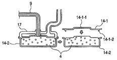
このような粉体充填装置を用いて、粉体の充填を行う場合には、被充填容器14としては、蓋14−1と粉体収納部14−2から構成されたものが用いられる(図5参照)。
A characteristic part of the filling apparatus according to the third embodiment is that the rear end portion of the conveyance path (conveyance tube 9) connected to the discharge portion for feeding the powder into the filling container is the powder of the filling container. It is formed with the
When powder filling is performed using such a powder filling apparatus, the
充填時においては、被充填容器の蓋14−1を外して、被充填容器14の粉体収納部14−2に充填された粉体層の表面形状として求められる形状と実質的に等しい形状を有している該後端部を、粉体収納部14−2に接合し、粉体の充填が行われる。
At the time of filling, the lid 14-1 of the container to be filled is removed, and a shape substantially equal to the shape required as the surface shape of the powder layer filled in the powder container 14-2 of the
次に、脱気装置17の構成について図4を用いて説明する。
脱気装置17は、脱気装置枠体17−1、粉体導入部17−2、蓋形状フィルター(脱気フィルター)17−3(フィルター凹部17−6、フィルター凸部17−7)、負圧接続部17−4、脱気パッキン17−5とを有する。
脱気装置枠体17−1は、被充填容器14の蓋14−1と粉体収納部14−2との接合部に沿った形状をしており、粉体収納部14−2に対して上方から嵌合する。なお、嵌合部には嵌合状態を密にする脱気パッキン17−5が設けられている。脱気装置枠体17−1の接合部と反対側には負圧接続部17−4が設けられ、この部分と負圧源とが接続されており、脱気が行われる。
また、粉体導入部17−2は本実施例においては中央部に1ヶ所設けているが、充填速度向上のため、粉体導入部17−2部を複数設けても良いし、また、位置についても中央部ではなく端部であっても良い。
更に蓋形状フィルター17−3については、五層の金属焼結フィルターを使用し、その目開きは粉体4と接する側から1層目:縦、横ともに150μm(100メッシュ)、2層目:縦7.5μm(2000メッシュ)、横10.7μm(1400メッシュ)、3層目:縦、横ともに150μm(100メッシュ)、4層目:縦1400μm(12メッシュ)、横234μm(64メッシュ)、5層目:縦1400μm(12メッシュ)、横234μm(64メッシュ)といったフィルターを用いた。但し、蓋形状フィルター17−3の構成については上記構成に限定するものではなく、粉体4を通過せずに気体のみを通過できる構成であれば良い。
このような脱気装置17を用いることで、主に被充填容器14内にて粉体層に含まれた気体を脱気することができ、その結果、粉体4を高密度に充填できる。
Next, the configuration of the
The
The deaerator frame 17-1 has a shape along the joint between the lid 14-1 of the
In addition, in the present embodiment, the powder introduction portion 17-2 is provided at one central portion, but a plurality of powder introduction portions 17-2 may be provided to improve the filling speed. Also, the end portion may be used instead of the central portion.
Further, for the lid-shaped filter 17-3, a five-layer sintered metal filter is used, and the opening is the first layer from the side in contact with the powder 4: 150 μm (100 mesh) both vertically and horizontally, and the second layer: 7.5 μm in length (2000 mesh), 10.7 μm in width (1400 mesh), 3rd layer: 150 μm (100 mesh) in both length and width, 4th layer: 1400 μm in length (12 mesh), 234 μm in width (64 mesh), 5th layer: A filter having a length of 1400 μm (12 mesh) and a width of 234 μm (64 mesh) was used. However, the configuration of the lid-shaped filter 17-3 is not limited to the above-described configuration, and any configuration that allows only gas to pass without passing through the
By using such a
次に蓋14−1の接合について図5を用いて説明する。
粉体4が粉体収納部14−2に所定量充填されたことが検知されたら、粉体排出バルブ13を閉じて粉体4の排出を止める。その後、脱気装置17は粉体収納部14−2から外され、別途用意された蓋14−1と粉体収納部14−2とが接合される。例えば、この蓋14−1と粉体収納部14−2との接合は、公知の手段である超音波溶着等により行われる。
Next, joining of the lid 14-1 will be described with reference to FIG.
When it is detected that a predetermined amount of the
また、脱気装置17を用いることで、粉体収納部14−2に充填した粉体層の表面形状を蓋14−1の内面側形状と実質的に等しい形状に容易に成形できる。凹部や凸部を有する蓋を用いる場合には、粉体収納部14−2に充填された粉体層の表面形状を成形しておくことが好ましい。例えば、蓋14−1に凹部14−1−1がある場合には、蓋形状フィルター17−3に前記凹部に合わせた凹部17−6を設けることで、その凹部にまで粉体を充填可能となり、更に多くの粉体を充填することが可能となる。また、蓋14−1に凸部14−1−2がある場合においては、蓋形状フィルター17−3に前記凸部に合わせた凸部17−7を設けることで、次工程である蓋14−1を載せて接合する工程において、蓋14−1を載せることに伴う粉体4の飛散を少なくすることができる。なお、凸部17−7についてはフィルター17−3を加工して設けてもよく、脱気枠体17−1にフィルター機能を有さない凸部を設けても良い。
Further, by using the
図5には蓋14−1の中央部に凹部14−1−1がある構成を示している。このように蓋14−1に凹部14−1−1がある構成においては、凹部14−1−1に十分に充填を行うことは困難であるが、本構成のように、蓋形状フィルター17−3に凹部14−1−1に実質的に合わせた凹部17−6を設けることで、脱気により粉体4を蓋形状フィルター17−3の形状に成形できるため、凹部14−1−1にも十分に充填できる。
FIG. 5 shows a configuration in which a recess 14-1-1 is provided at the center of the lid 14-1. Thus, in the configuration in which the lid 14-1 has the recess 14-1-1, it is difficult to sufficiently fill the recess 14-1-1. However, as in this configuration, the lid-shaped filter 17- 3 is provided with a concave portion 17-6 substantially matched with the concave portion 14-1-1 so that the
一方、蓋14−1の側端部には凸部14−1−2が設けてある。このように蓋14−1の側端部に凸部14−1−2が設けてある構成においては、蓋14−1を粉体収納部14−2に装着する工程において、蓋14−1の凸部14−1−2により粉体4が押し出され、粉体4の飛散が発生しやすい。しかしながら、脱気装置17に蓋14−1に合わせた凸形状17−7を設けることで、蓋14−1の凸部14−1−2に対応する部分の粉体4を予め除くことができ、その結果、粉体4の飛散を軽減することができる。
On the other hand, the convex part 14-1-2 is provided in the side edge part of the lid | cover 14-1. As described above, in the configuration in which the convex portion 14-1-2 is provided at the side end of the lid 14-1, in the step of attaching the lid 14-1 to the powder container 14-2, The
即ち、粉体4の飛散を軽減することで粉体4のムダを防止でき、更には蓋14−1と粉体収納部14−2との接合部への粉体4の巻き込みを防止でき、その結果、蓋14−1と粉体収納部14−2との接着の安定性が向上させることができる。
That is, the
なお、本実施例において、負圧源の負圧力は−5〜−10kPa程度が好ましい。前記脱気装置17を用いて脱気処理を行うことで、単位容積あたりの粉体の充填量を、0.35g/cm3から0.50g/cm3に向上させることができた。即ち、1000cm3の容積の被充填容器においては、粉体の充填量を350gから500gに増量することができた。
In this embodiment, the negative pressure of the negative pressure source is preferably about −5 to −10 kPa. By performing the deaeration process using the
(実施例4)
次に第4の実施例について説明する。
図6に第4実施例の充填装置の一例を示す。図6において、粉体貯留容器1、加圧ホッパ5、コンプレッサ6、搬送チューブ9、粉体導入バルブ10、加圧バルブ12、粉体排出バルブ13、内圧計15、ロードセル16等は実施例1と同じ構成であるので説明は省略する。尚、粉体4としては、実施例1で述べたものと同じ物を用いることができる。
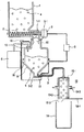
第4の実施例に係る充填装置の特徴的な部分は、加圧ホッパ5の下方円錐形状部の周面に脱気装置18を設けた点である。
Example 4
Next, a fourth embodiment will be described.
FIG. 6 shows an example of the filling device of the fourth embodiment. In FIG. 6, the powder storage container 1, the pressure hopper 5, the
A characteristic part of the filling device according to the fourth embodiment is that a
脱気装置18の構成について図7を用いて説明する。
脱気装置18は、脱気装置枠体18−1、フィルター(脱気フィルター)18−2、負圧接続部18−3、脱気バルブ18−4とを有する。
本実施例においては、脱気フィルター18−2として、実施例3で説明した脱気装置17のフィルターと同様の五層の金属焼結フィルターを使用したが、本フィルターの構成についても上記構成に限定するものではない。脱気フィルター18−2としては、粉体4を通過せずに気体のみを通過できるものであれば良い。
脱気バルブ18−4についても、気密状態を確保できるバルブであれば特に限定するものではなく、本実施例においてはピンチバルブを用いた。
The configuration of the
The
In this example, a five-layer sintered metal filter similar to the filter of the
The deaeration valve 18-4 is not particularly limited as long as it can ensure an airtight state, and a pinch valve is used in this embodiment.
次に本装置を用いた充填方法について説明する。
粉体貯留容器1に貯留された粉体4は搬送手段2によって、下方に設けた加圧ホッパ5へ搬送される。所定量の粉体4が加圧ホッパ5内に搬送された後、脱気バルブ18−4が開き、加圧ホッパ5内の粉体4の脱気が行われる。なお、脱気のタイミングは加圧ホッパ5に粉体4を搬送している段階に行っても良い。
所定時間脱気した後、脱気バルブ18−4、粉体導入バルブ10が閉じられ、加圧ホッパ5内が気密となり、その後、コンプレッサ6と加圧バルブ12により、加圧ホッパ5内が加圧される。内圧計15により、加圧ホッパ5内が所定圧に達したことが検知されると、信号が粉体排出バルブ13に送られ、粉体排出バルブ13が開かれ、粉体4の充填が開始される。
なお、以後の制御については、第1の実施例と同じであるので、説明は省略する。
上記に述べた脱気装置18を用いる場合、圧力−5〜−10kPa程度で脱気を行うことが好ましい。
Next, a filling method using this apparatus will be described.
The
After deaeration for a predetermined time, the deaeration valve 18-4 and the
Since the subsequent control is the same as in the first embodiment, description thereof is omitted.
When the
本実施例においては、脱気装置18を用いて−10kPaで脱気処理を行った後、加圧ホッパに導入圧40kPaを加え、実施例1と同様にして充填を行うことで、搬送チューブ9から排出される粉体の見かけ嵩密度を、脱気処理を行わない場合の見かけ嵩密度0.35g/cm3から0.40g/cm3に向上させることができた。
In the present embodiment, after carrying out the deaeration process at −10 kPa using the
(実施例5)
次に、第5の実施例について説明する。
図9に第5の実施例に係る充填装置の一例を示す。図9において、粉体貯留容器1、加圧ホッパ5、コンプレッサ6、駆動制御装置8、搬送チューブ9、粉体導入バルブ10、加圧バルブ12、粉体排出バルブ13、内圧計15、ロードセル16等は実施例1と同じ構成であるので説明は省略する。尚、粉体4としては、実施例1で述べたものと同じ物であっても良いが、本実施例においては磁性1成分トナーを用いた。
第5の実施例に係る充填装置の特徴的な部分は、加圧ホッパと前記被充填容器との間に、前記粉体を貯留する貯留部が設けられた点である。
(Example 5)
Next, a fifth embodiment will be described.
FIG. 9 shows an example of a filling apparatus according to the fifth embodiment. In FIG. 9, the powder storage container 1, the pressure hopper 5, the
A characteristic part of the filling apparatus according to the fifth embodiment is that a storage part for storing the powder is provided between the pressure hopper and the container to be filled.
次に貯留部19の構成について説明する。
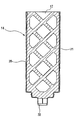
貯留部19は、貯留部枠体19−1、貯留部フィルター19−2、接続部19−3、シャッター19−4、貯留部粉体排出口19−5とを有する。なお貯留部19は内径100mmの円筒形状であり、貯留部粉体排出口19−5も内径100mmである。一方、対応する被充填容器14は内径120mmの円筒形状を有している。
本実施例においては、貯留部フィルター19−2として、実施例3で説明した脱気装置17のフィルターと同様の五層の金属焼結フィルターを使用したが、本フィルターの構成についても上記構成に限定するものではない。貯留部フィルター19−2としては、粉体4を通過せずに気体のみを通過できるものであれば良い。
シャッター19−4は、スライドして貯留部19の下方に設けられた貯留部粉体排出口19−5を封止状態と開封状態とに制御する。
Next, the configuration of the
The
In this example, a five-layer sintered metal filter similar to the filter of the
The shutter 19-4 slides and controls the storage unit powder discharge port 19-5 provided below the
次に本装置を用いた充填方法についても図9を用いて説明する。
粉体4は加圧ホッパ5内に注入された空気圧により、粉体排出バルブ13を開放することで搬送チューブ9を経て貯留部19に搬送される。このとき、貯留部19の貯留部粉体排出口19−5はシャッター19−4により気密に封止されているため、粉体4は貯留部19に粉体の飛散などを起こすことなく充填できる。貯留部19に設けられた接続部19−3を負圧源に接続することで、貯留部フィルター19−2を介して貯留部19内を脱気しながら粉体4の充填が行える。従って、粉体4は貯留部19の充填されるともに脱気され、その結果、粉体4の見かけ密度は高まり、その体積は減少する。一方、その間も搬送チューブ9を経て粉体4は貯留部19に充填され続けるため、粉体4の体積が減少したその減少分にも即座に充填が行え、その結果、粉体4を高密度に、且つ、早く充填できるのである。なお、図9では、貯留部フィルター19−2と接続部19−3とにより貯留部内を脱気した例を示しているが、貯留部19内の空気を抜くだけであれば、接続部19−3を有さないものであっても良い。この場合、貯留部19内は強制的に脱気されることはないが、加圧ホッパ5からの圧力により、粉体4は貯留部フィルター19−2に押し付けられるように充填され、比較的高密度な状態で充填できる。
Next, a filling method using this apparatus will be described with reference to FIG.
The
次に貯留部19に充填した粉体4を被充填容器14に充填する状況を図10A及び10Bを用いて説明する。所定量粉体4が充填されたことが検知された後、粉体バルブ13が閉じられる。その時の貯留部19の状態が図10Aである。その後、シャッター19−4を開封することで、貯留部19内の粉体4が被充填容器14へ充填される。なお、シャッター19−4の開封と共に、接続部19−3を加圧源に接続し貯留部フィルター19−2を介し貯留部9に空気を逆に注入しても良い。空気を注入することで、負圧により貯留部フィルター19−2の表面に付着していた粉体4は貯留部フィルター19−2から剥がされ、その結果、貯留部フィルター19−2に付着し、残留する粉体4を低減させることができる。また、更には貯留部フィルター19−2の目詰りを防止でき、その結果、貯留部フィルター19−2の寿命の延長できる。また、更には貯留部フィルター19−2の通気性能を維持することができ、その結果、充填精度を良化でき、また、長期にわたる充填の安定化を図ることができる。なお、空気を注入の無くした場合、貯留部19への充填を繰り返し行うと、たまに、今まで出来ていた充填量の充填が途中で止まって出来なくなる現象が見られた。更に、その状態で貯留部フィルター19−2を使用し続けると、貯留部フィルター19−2の目に完全に粉体4が詰まってしまい、空気で洗浄しても粉体4が抜けなくなってしまう。その状態となると、前記貯留部フィルター19−2を交換する必要があり、結果として充填後に貯留部フィルター19−2に空気の注入を行うことで、貯留部フィルター19−2の寿命が延長できるのである。
Next, a situation where the filling
シャッター19−4の開封とともに、粉体4は貯留部19から被充填容器14へ重力により落下し充填される。その時の充填状況を観察すると、粉体4は貯留部での締め固められた状態のまま落下するため、落下時に空気をまき込みずらく、その結果、嵩密度を低下させずに被充填容器14に充填される。その時の貯留部19と被充填容器14の状態が図10Bである。なお、この充填時に被充填容器14側に振動をかけると、粉体4の粉面が平らにできるため、蓋の装着時における粉体4の飛散を防止でき、更には充填率の向上も見込める。
With the opening of the shutter 19-4, the
また、貯留部19の内径が100mmであるのに対し、被充填容器14の内径及び充填口の内径は120mmであるため、貯留部19から被充填容器14へ粉体4を充填する際、被充填容器14の外への飛散を抑制できる。なお、貯留部19と被充填容器14との接合部をシールするシール部材を貯留部19側、又は、被充填容器14側に別途設けてもよい。そして、粉体4が十分に被充填容器14に充填された後、蓋14−1を接着することにより封止し、被充填容器14への充填が完了となる。この状況を示したのが図11である。
In addition, since the inner diameter of the
上記構成において、内周100mmの周面全域にフィルターを設けた高さ410mm、内容積3200cm3の貯留部19を設けた充填装置を用い、磁性1成分トナーを用いて充填を行ったところ、貯留部19内での充填量は2300g〜2370gであり、単位容積あたりの充填量は約0.72g/cm3〜0.74g/cm3であった。また、被充填容器14として内径120mm、高さ300mm、内容積3390cm3の円筒状の容器を用いた場合、被充填容器14へ300mm落下させて充填した後においても単位容積あたりの充填量で約0.68g/cm3〜0.70g/cm3で充填することができた。なお、充填は、加圧ホッパ4への導入圧を100kPa、貯留部19の脱気圧を−20kPaとし、搬送チューブは、内径15mmのシリコーン樹脂製のものを用いて行った。
In the above configuration, when a filling device provided with a
一方、貯留部19内を脱気しなかった場合であっても、貯留部19における充填量は約2240gであって、貯留部19における単位容積あたりの充填量は約0.70g/cm3であった。
On the other hand, even if the inside of the
また、上記の如くにして被充填容器に充填された磁性1成分トナーを目開き38μm(400メッシュ)の篩いを通したところ、充填の前後で篩上に残る粒子数は、貯留部を経由させずに充填を行った場合に比べて増加傾向は見られなかった。 Further, when the magnetic one-component toner filled in the container to be filled as described above is passed through a sieve having an opening of 38 μm (400 mesh), the number of particles remaining on the sieve before and after filling passes through the storage section. No increase was observed compared to the case where the filling was performed.
尚、本実施例5においては、実施例1の如き充填装置において貯留部を設けた構成としたが、実施例2乃至4の如き構成を有する充填装置に貯留部を設ける構成とすることもできる。 In the fifth embodiment, the storage device is provided in the filling device as in the first embodiment. However, the storage device may be provided in the filling device having the configuration as in the second to fourth embodiments. .
(実施例6)
次に、第6の実施例について説明する。
第6の実施例においては、図1の搬送チューブ9の後端部に図12に示される被充填容器を、被充填容器粉体充填口よりも上方に被充填容器脱気部がくるように接続したことを特徴とする。
(Example 6)
Next, a sixth embodiment will be described.
In the sixth embodiment, the filled container shown in FIG. 12 is placed at the rear end of the transfer tube 9 in FIG. 1, and the filled container deaeration part is positioned above the filled container powder filling port. It is connected.
先ず、被充填容器14の構成について図12を用いて説明する。
被充填容器14には、粉体を収容する粉体収容部20と、内部粉体を撹拌搬送する搬送部材21、搬送チューブとの接続部が設けられた被充填容器粉体充填口22が設けられており、前記被充填容器粉体充填口22から粉体収容部20内に粉体4が充填される。また粉体4を充填する際には、粉体収容部20からの粉体4の漏れが無いように、被充填容器粉体充填口22、脱気部17は不図示のシール材等で隙間は完全に密閉された状態であることが好ましい。また、図示した搬送部材21の構成については特に制限は無く、被充填容器が自転や公転することによって、内部の粉体を搬送するように、粉体収容部20の内壁にらせん状の溝(不図示)が設けられていても良い。
First, the configuration of the filling
The filling
続いて、図13を用いて、被充填容器脱気部17の構成について説明する。
被充填容器14の粉体収容部20への粉体4の充填が行われる搬送チューブ9に接続された被充填容器粉体充填口22よりも上方に被充填容器脱気部17がくるようにして充填は行われる。図13に示すように被充填容器脱気部17は主に、粉体4を遮断し粉体収容部20内の気体を通過可能な被充填容器脱気フィルター17−1と、被充填容器脱気フィルター17−1と一体化し、粉体収容部20に接続するための枠体17−2、粉体収容部20と被充填容器脱気部17との接続部からの粉体4の漏れを防ぐシール材17−3によって構成される。すなわち、被充填容器脱気部17に被充填容器脱気フィルター17−1を密閉した状態で設けることにより、粉体収容部20内の気体のみを確実に脱気できる。
Then, the structure of the to-be-filled
The filled
粉体収容部20において、被充填容器粉体充填口22よりも上方に被粉体容器脱気部17を配置することで、脱気をスムーズに行うことができ、粉体4の充填密度を高めることが可能となる。また、粉体収容部20の鉛直方向下端部に被充填容器粉体充填口22を接続し、前記被充填容器粉体充填口22に対向する粉体収容部20の鉛直方向上端部に被充填容器脱気部17を接続することがより好ましく、本実施例においては、このような構成で粉体の充填を行った。
In the
本実施例においては、被充填容器脱気フィルター17−1として、実施例3で説明した脱気装置のフィルターと同様の五層の金属焼結フィルターを使用したが、本フィルターの構成については上記構成に限定するものではない。被充填容器脱気フィルター17−1としては、粉体4を通過せずに気体のみを通過できるものであれば良い。尚、本実施例においては、脱気装置を用いなかったが、被充填容器脱気フィルターに脱気装置を接続し、積極的に脱気することもできる。
In this example, a five-layered sintered metal filter similar to the filter of the deaeration apparatus described in Example 3 was used as the filling container deaeration filter 17-1, but the configuration of the filter was as described above. The configuration is not limited. The filling container deaeration filter 17-1 may be any filter that can pass only gas without passing through the
本実施例においては、加圧ホッパへの導入圧を50kPaとして、被充填容器内を脱気しながら、被充填容器粉体充填口より磁性1成分トナーの充填を行ったところ、0.70g/cm3の高密度な充填をスムーズに行うことができた。 In this embodiment, when the pressure introduced into the pressure hopper is 50 kPa and the magnetic one-component toner is filled from the filling container powder filling port while degassing the inside of the filling container, 0.70 g / A high-density filling of cm 3 could be performed smoothly.
尚、本実施例6においては、実施例1の如き充填装置において被充填容器を変更した構成としたが、実施例2乃至4の如き構成を有する充填装置において被充填容器を変更した構成とすることもできる。 In the sixth embodiment, the filling container is changed in the filling apparatus as in the first embodiment. However, the filling container is changed in the filling apparatus having the structure as in the second to fourth embodiments. You can also.
(実施例7)
次に、第7の実施例について説明する。
第7の実施例においては、図1の搬送チューブ9の後端部に、図15に示される被充填容器脱気部を装着した図14に示される被充填容器を接続したことを特徴とする。
(Example 7)
Next, a seventh embodiment will be described.
The seventh embodiment is characterized in that the filling container shown in FIG. 14 equipped with the filling container deaeration unit shown in FIG. 15 is connected to the rear end of the transfer tube 9 shown in FIG. .
先ず、被充填容器14の構成について図14、図15を用いて説明する。
図14に示すように被充填容器14には、粉体収容部20と、粉体収容部20の上方から下方へ延在する充填補助管29、封止キャップ30が設けられている。また、粉体収容部20内の不図示の規制部によって、充填補助管29の下端部23と粉体収容部20の底部とは、1〜120mmの距離を有して保持されることが好ましく、より好ましくは15〜85mmである。この範囲内である場合に、特に良好に粉体の飛散の抑制とスムーズな充填を両立できる。
First, the configuration of the filling
As shown in FIG. 14, the filling
被充填容器14が充填時の姿勢において、充填補助管29の上端部22が被充填容器粉体充填口7と接続される。粉体4は、被充填容器粉体充填口7より導入され、充填補助管29内を経て充填補助管29の下端部23より、粉体4の層面が粉体収容部20の底部から徐々に上昇するようにして、粉体収容部20内へ充填される。また、粉体収容部20の上部には被充填容器脱気部17が接続されており、粉体収容部20内の気体を被充填容器脱気部17より粉体収容部20外へ脱気しながら、粉体収容部20内への粉体4の充填が行われる。尚、本実施例においては、粉体収容部は長手の長さが350mmであり、充填補助管29は内径が15mm、長手の長さが300mmであり、充填補助管29の下端部23と粉体収容部20の底部との距離が約50mmであった。また、搬送チューブ9としては内径15mmのものを用いた。
In the posture when the filling
次いで、被充填容器脱気部17の構成について説明する。
被充填容器脱気部17は、充填時の姿勢において、被充填容器粉体導入部7が接続される充填補助管29の上端部22を避けるように、粉体収容部20の上部に配置される。図15に示すように被充填容器脱気部17は主に、粉体4を遮断し、粉体収容部20内の気体を通過可能な被充填容器脱気フィルター17−1と、被充填容器脱気フィルター17−1と一体化し、粉体収容部20に接続するための枠体17−2、粉体収容部20と被充填容器脱気部17との接続部からの粉体4の漏れを防ぐシール材17−3によって構成される。すなわち、被充填容器脱気部17に被充填容器脱気フィルター17−1を密閉した状態で接続されることにより、粉体収容部20内の気体のみを確実に脱気でき、粉体収容部20からの粉体の飛散を防止することができる。また、枠体17−2は粉体収容部20に装着し易いように、粉体収容部20の内周に入りこむようなインロー形状となっていることが好ましい。
Next, the configuration of the filling
The filling
また、搬送チューブ9の先端に接続された被充填容器粉体充填口7が、被充填容器脱気フィルター17−1を貫通して、被充填容器脱気部17と一体に設けられている。さらに、被充填容器粉体充填口7の先端には充填補助管29と被充填容器粉体充填口7とを密閉し接続する密閉シール31が設けられている。この密閉シール31によって、被充填容器粉体充填口7から噴出された粉体4が接続部から漏れること無く、確実に充填補助管29内に案内される。ここで、上記密閉シール31は後述する充填補助管29の上端部に設けてあっても良い。
Further, a filling container powder filling port 7 connected to the tip of the transfer tube 9 penetrates the filling container deaeration filter 17-1 and is provided integrally with the filling
本実施例においては、被充填容器脱気フィルター17−1として、実施例3で説明した脱気装置のフィルターと同様の五層の金属焼結フィルターを使用したが、本フィルターの構成については上記構成に限定するものではない。被充填容器脱気フィルター17−1としては、粉体4を通過せずに気体のみを通過できるものであれば良い。尚、本実施例においては、脱気装置を用いなかったが、被充填容器脱気フィルターに脱気装置を接続し、積極的に脱気することもできる。
In this example, a five-layered sintered metal filter similar to the filter of the deaeration apparatus described in Example 3 was used as the filling container deaeration filter 17-1, but the configuration of the filter was as described above. The configuration is not limited. The filling container deaeration filter 17-1 may be any filter that can pass only gas without passing through the
本実施例においては、加圧ホッパへの導入圧を50kPaとして、被充填容器内を脱気しながら、被充填容器粉体充填口より磁性1成分トナーの充填を行ったところ、0.69g/cm3の高密度な充填をスムーズに行うことができた。 In this embodiment, when the pressure introduced into the pressure hopper is 50 kPa and the magnetic one-component toner is filled from the filling container powder filling port while degassing the inside of the filling container, 0.69 g / A high-density filling of cm 3 could be performed smoothly.
尚、本実施例7においては、実施例1の如き充填装置において被充填容器を変更した構成としたが、実施例2乃至4の如き構成を有する充填装置において被充填容器を変更した構成とすることもできる。 In the seventh embodiment, the filling container is changed in the filling apparatus as in the first embodiment. However, the filling container is changed in the filling apparatus having the structure as in the second to fourth embodiments. You can also.
1 粉体貯留容器
2 搬送手段
3 駆動手段
4 粉体
5 加圧ホッパ
6 コンプレッサ
8 駆動制御装置
9 (粉体)搬送チューブ
10 粉体導入バルブ
12 加圧バルブ
13 粉体排出バルブ
15 内圧計
16 ロードセル
5−1 粉体導入口
5−2 粉体排出口(粉体排出開口部)
14 被充填容器
1−1 開口部
7 補助容器
11 補助容器用バルブ
7−1 フィルター
17 脱気装置
14−1 被充填容器の蓋
14−2 被充填容器の粉体収納部
17−1 脱気装置枠体
17−2 粉体導入部
17−3 蓋形状フィルター(脱気フィルター)
17−4 負圧接続部
17−5 脱気パッキン
17−6 フィルター凹部
17−7 フィルター凸部
14−1−1 蓋凹部
14−1−2 蓋凸部
18 脱気装置
18−1 脱気装置枠体
18−2 フィルター(脱気フィルター)
18−3 負圧接続部
18−4 脱気バルブ
19 貯留部
19−1 貯留部枠体
19−2 貯留部フィルター
19−3 接続部
19−4 シャッター
19−5 貯留部粉体排出口
20 粉体収容部
21 搬送部材
23 充填補助管の下端部
22 被充填容器粉体充填口
29 充填補助管
30 封止キャップ
DESCRIPTION OF SYMBOLS 1
14 Filled Container 1-1 Opening 7
17 Deaerator 14-1 Cap 14-2 of Filled Container Powder Storage Unit 17-1 of Filled Container 17-1 Deaerator Frame 17-2 Powder Introducing Unit 17-3 Cover Shape Filter (Degas Filter)
17-4 Negative pressure connection part 17-5 Deaeration packing 17-6 Filter concave part 17-7 Filter convex part 14-1-1 Cover concave part 14-1-2 Cover
18-3 Negative pressure connection part 18-4
Claims (21)
前記加圧ホッパが、粉体を排出する排出部と、少なくとも前記加圧ホッパ内の粉体により形成される粉体層表面よりも上方に位置する気体導入部とを有しており、
前記加圧ホッパと前記粉体層とが接する部分の少なくとも一部に、加圧ホッパ内の粉体層中に含まれる気体を脱気するためのフィルターが設けられており、該フィルターは空気を通し粉体を遮断するものであり、
前記粉体層は加圧ホッパ内において前記排出部を塞ぐように形成されるものであり、
前記排出部を閉じた状態で、前記気体導入部より気体を導入して、前記加圧ホッパ内を加圧し、加圧後、前記排出部を開放することにより、圧力を利用して、前記排出部を塞ぐように形成されている粉体層を排出し、粉体を被充填容器に充填することを特徴とする粉体充填装置。 A powder filling apparatus having a pressure hopper,
The pressure hopper has a discharge part for discharging powder, and a gas introduction part located at least above the surface of the powder layer formed by the powder in the pressure hopper;
A filter for degassing the gas contained in the powder layer in the pressure hopper is provided in at least a part of the portion where the pressure hopper and the powder layer are in contact with each other. To block through powder,
The powder layer is formed so as to block the discharge part in a pressure hopper,
With the discharge portion closed, the gas is introduced from the gas introduction portion, the inside of the pressure hopper is pressurized, and after the pressurization, the discharge portion is opened to utilize the pressure. A powder filling apparatus for discharging a powder layer formed so as to close a portion and filling the container with the powder.
前記加圧ホッパが、粉体を排出する排出部と、少なくとも前記加圧ホッパ内の粉体により形成される粉体層表面よりも上方に位置する気体導入部とを有しており、
前記加圧ホッパと前記被充填容器との間に、前記粉体を貯留する貯留部が設けられており、
前記貯留部は、少なくともその壁面の一部が、空気を通し粉体を遮断する貯留部フィルターで構成されており、
前記貯留部は、前記粉体を前記被充填容器へと排出する貯留部粉体排出口を封止するシャッターを有しており、
前記粉体層は加圧ホッパ内において前記排出部を塞ぐように形成されるものであり、
前記排出部を閉じた状態で、前記気体導入部より気体を導入して、前記加圧ホッパ内を加圧し、加圧後、前記排出部を開放することにより、圧力を利用して、前記排出部を塞ぐように形成されている粉体層を排出し、粉体を被充填容器に充填することを特徴とする粉体充填装置。 A powder filling apparatus having a pressure hopper,
The pressure hopper has a discharge part for discharging powder, and a gas introduction part located at least above the surface of the powder layer formed by the powder in the pressure hopper;
A reservoir for storing the powder is provided between the pressure hopper and the container to be filled.
The reservoir is configured by a reservoir filter in which at least a part of the wall surface blocks the powder through air,
The storage unit has a shutter that seals a storage unit powder discharge port for discharging the powder to the filled container ,
The powder layer is formed so as to block the discharge part in a pressure hopper,
With the discharge portion closed, the gas is introduced from the gas introduction portion, the inside of the pressure hopper is pressurized, and after the pressurization, the discharge portion is opened to utilize the pressure. A powder filling apparatus for discharging a powder layer formed so as to close a portion and filling the container with the powder.
前記加圧ホッパが、粉体を排出する排出部と、少なくとも前記加圧ホッパ内の粉体により形成される粉体層表面よりも上方に位置する気体導入部とを有しており、
前記加圧ホッパと前記粉体層とが接する部分の少なくとも一部に、空気を通し粉体を遮断するフィルターが設けられており、前記フィルターを介して加圧ホッパ内の粉体層に含まれる気体を脱気した後、被充填容器への粉体の充填が行われ、
前記粉体層は加圧ホッパ内において前記排出部を塞ぐように形成し、
前記排出部を閉じた状態で、前記気体導入部より気体を導入して、前記加圧ホッパ内を加圧し、加圧後、前記排出部を開放することにより、圧力を利用して、前記排出部を塞ぐように形成されている粉体層を排出し、粉体を被充填容器に充填することを特徴とする粉体充填方法。 A powder filling method performed using a powder filling apparatus having a pressure hopper,
The pressure hopper has a discharge part for discharging powder, and a gas introduction part located at least above the surface of the powder layer formed by the powder in the pressure hopper;
At least a part of the portion where the pressure hopper and the powder layer are in contact with each other is provided with a filter that blocks air through the air and is included in the powder layer in the pressure hopper via the filter. After degassing the gas, the container is filled with powder,
The powder layer is formed in the pressure hopper so as to block the discharge part,
With the discharge portion closed, the gas is introduced from the gas introduction portion, the inside of the pressure hopper is pressurized, and after the pressurization, the discharge portion is opened to utilize the pressure. A powder filling method characterized by discharging a powder layer formed so as to close the portion and filling the filling container with the powder.
前記貯留部は、少なくともその壁面の一部が、空気を通し粉体を遮断する貯留部フィルターで構成されており、
前記貯留部は、前記粉体を前記被充填容器へと排出する貯留部粉体排出口を封止するシャッターを有しており、
前記貯留部粉体排出口が前記シャッターにより封止されている状態で、前記粉体を前記加圧ホッパから前記貯留部へ前記粉体を充填し、その後、前記シャッターを開放することで前記粉体を貯留部より被充填容器へと充填することを特徴とする請求項12乃至19のいずれかに記載の粉体充填方法。 A reservoir for storing the powder is provided between the pressure hopper and the container to be filled.
The reservoir is configured by a reservoir filter in which at least a part of the wall surface blocks the powder through air,
The storage unit has a shutter that seals a storage unit powder discharge port for discharging the powder to the filled container,
In a state where the storage unit powder discharge port is sealed by the shutter, the powder is filled into the storage unit from the pressure hopper, and then the shutter is opened to release the powder. The powder filling method according to any one of claims 12 to 19 , wherein the body is filled into the filling container from the storage part.
前記被充填容器内に粉体を送り込む排出部の後端部が前記充填補助管の上端部に接続され、
前記粉体収容部内の気体を前記被充填容器脱気部から脱気しながら、粉体を前記粉体収容部へ前記充填補助管を通して充填することを特徴とする請求項12乃至20のいずれかに記載の粉体充填方法。 The container to be filled has a powder container for containing powder and a container deaeration unit to be filled, and the container to be filled is in a vertically upper position with respect to the powder container in a posture at the time of filling. A filling auxiliary pipe extending downward from the side, and the filled container degassing part is arranged vertically above the powder container,
The rear end of the discharge part for feeding powder into the container to be filled is connected to the upper end of the auxiliary filling pipe,
While degassed gas in the powder accommodating portion from the the filling container deaerating section, any one of claims 12 to 20 powder, characterized in that filling through the filling auxiliary tube to the powder accommodating portion The powder filling method according to 1.
Priority Applications (1)
| Application Number | Priority Date | Filing Date | Title |
|---|---|---|---|
| JP2007048405A JP5121253B2 (en) | 2006-02-28 | 2007-02-28 | Powder filling apparatus, powder filling method and process cartridge |
Applications Claiming Priority (3)
| Application Number | Priority Date | Filing Date | Title |
|---|---|---|---|
| JP2006052216 | 2006-02-28 | ||
| JP2006052216 | 2006-02-28 | ||
| JP2007048405A JP5121253B2 (en) | 2006-02-28 | 2007-02-28 | Powder filling apparatus, powder filling method and process cartridge |
Related Child Applications (1)
| Application Number | Title | Priority Date | Filing Date |
|---|---|---|---|
| JP2012153366A Division JP5539450B2 (en) | 2006-02-28 | 2012-07-09 | Powder filling apparatus, powder filling method and process cartridge |
Publications (3)
| Publication Number | Publication Date |
|---|---|
| JP2007261687A JP2007261687A (en) | 2007-10-11 |
| JP2007261687A5 JP2007261687A5 (en) | 2010-04-22 |
| JP5121253B2 true JP5121253B2 (en) | 2013-01-16 |
Family
ID=38635073
Family Applications (1)
| Application Number | Title | Priority Date | Filing Date |
|---|---|---|---|
| JP2007048405A Expired - Fee Related JP5121253B2 (en) | 2006-02-28 | 2007-02-28 | Powder filling apparatus, powder filling method and process cartridge |
Country Status (1)
| Country | Link |
|---|---|
| JP (1) | JP5121253B2 (en) |
Families Citing this family (2)
| Publication number | Priority date | Publication date | Assignee | Title |
|---|---|---|---|---|
| JP5982759B2 (en) | 2011-09-06 | 2016-08-31 | ブラザー工業株式会社 | Powder filling equipment |
| CN109018560A (en) * | 2018-07-02 | 2018-12-18 | 湖南科伦制药有限公司 | A kind of pulvis packing loading amount detection system |
Family Cites Families (2)
| Publication number | Priority date | Publication date | Assignee | Title |
|---|---|---|---|---|
| JPS62109702A (en) * | 1985-07-03 | 1987-05-20 | 上田 博巳 | Powdered and granular body filler |
| JP3978262B2 (en) * | 1997-08-07 | 2007-09-19 | インターメタリックス株式会社 | Filling method and apparatus |
-
2007
- 2007-02-28 JP JP2007048405A patent/JP5121253B2/en not_active Expired - Fee Related
Also Published As
| Publication number | Publication date |
|---|---|
| JP2007261687A (en) | 2007-10-11 |
Similar Documents
| Publication | Publication Date | Title |
|---|---|---|
| JP5539450B2 (en) | Powder filling apparatus, powder filling method and process cartridge | |
| JP4108901B2 (en) | Powder filling method, powder filling apparatus and tubular body | |
| US6679301B2 (en) | Powder packing method and apparatus therefor | |
| WO2004083038A1 (en) | Powder charging device and powder charging method | |
| EP1568609B1 (en) | Apparatus and method of filling microscopic powder | |
| KR100861039B1 (en) | Transferring method of powder toner for electrophotograph and transferring apparatus thereof, and filling method of powder toner and the filling apparatus thereof | |
| JPH08198203A (en) | Method and apparatus for filling powder | |
| JPH08198202A (en) | Method and apparatus for filling powder | |
| JP5121253B2 (en) | Powder filling apparatus, powder filling method and process cartridge | |
| JP3547730B2 (en) | Filling method and filling device for fine powder | |
| JP2009051544A (en) | Granule filling device and granule filling method | |
| JP2009051544A5 (en) | ||
| JP2002337801A (en) | Method and apparatus of filling extra-fine powder | |
| JP3457717B2 (en) | Powder filling equipment | |
| JP4274537B2 (en) | Powder filling method | |
| WO2004063010A1 (en) | Powder filling method, powder filling device, and powder filling nozzle | |
| JP4397640B2 (en) | Powder filling nozzle, powder filling apparatus and powder filling method | |
| JP2008074415A (en) | Powder filling method and powder filling device | |
| JP6083686B2 (en) | Powder body filling device and filling pipe unit | |
| JP2005053550A (en) | Method and apparatus for filling powder, and filling nozzle | |
| JP2005075374A (en) | Fine powder filling apparatus | |
| JP2005067653A (en) | Method for filling powder and system for filling powder | |
| JP4335600B2 (en) | Powder filling method and filling device | |
| JP2005075375A (en) | Powder filling method and powder filling apparatus | |
| JP2004299787A (en) | Filling device of powdered matter and method of filling using the same |
Legal Events
| Date | Code | Title | Description |
|---|---|---|---|
| A621 | Written request for application examination |
Free format text: JAPANESE INTERMEDIATE CODE: A621 Effective date: 20100226 |
|
| A521 | Written amendment |
Free format text: JAPANESE INTERMEDIATE CODE: A523 Effective date: 20100305 |
|
| RD04 | Notification of resignation of power of attorney |
Free format text: JAPANESE INTERMEDIATE CODE: A7424 Effective date: 20100617 |
|
| RD05 | Notification of revocation of power of attorney |
Free format text: JAPANESE INTERMEDIATE CODE: A7425 Effective date: 20100730 |
|
| RD04 | Notification of resignation of power of attorney |
Free format text: JAPANESE INTERMEDIATE CODE: A7424 Effective date: 20101227 |
|
| A131 | Notification of reasons for refusal |
Free format text: JAPANESE INTERMEDIATE CODE: A131 Effective date: 20120509 |
|
| A521 | Written amendment |
Free format text: JAPANESE INTERMEDIATE CODE: A523 Effective date: 20120709 |
|
| RD05 | Notification of revocation of power of attorney |
Free format text: JAPANESE INTERMEDIATE CODE: A7425 Effective date: 20120727 |
|
| RD05 | Notification of revocation of power of attorney |
Free format text: JAPANESE INTERMEDIATE CODE: A7425 Effective date: 20120730 |
|
| RD05 | Notification of revocation of power of attorney |
Free format text: JAPANESE INTERMEDIATE CODE: A7425 Effective date: 20120731 |
|
| RD03 | Notification of appointment of power of attorney |
Free format text: JAPANESE INTERMEDIATE CODE: A7423 Effective date: 20120831 |
|
| TRDD | Decision of grant or rejection written | ||
| A01 | Written decision to grant a patent or to grant a registration (utility model) |
Free format text: JAPANESE INTERMEDIATE CODE: A01 Effective date: 20121018 |
|
| A01 | Written decision to grant a patent or to grant a registration (utility model) |
Free format text: JAPANESE INTERMEDIATE CODE: A01 |
|
| A61 | First payment of annual fees (during grant procedure) |
Free format text: JAPANESE INTERMEDIATE CODE: A61 Effective date: 20121023 |
|
| FPAY | Renewal fee payment (event date is renewal date of database) |
Free format text: PAYMENT UNTIL: 20151102 Year of fee payment: 3 |
|
| FPAY | Renewal fee payment (event date is renewal date of database) |
Free format text: PAYMENT UNTIL: 20151102 Year of fee payment: 3 |
|
| LAPS | Cancellation because of no payment of annual fees |