JP5119752B2 - Work body - Google Patents
Work body Download PDFInfo
- Publication number
- JP5119752B2 JP5119752B2 JP2007151662A JP2007151662A JP5119752B2 JP 5119752 B2 JP5119752 B2 JP 5119752B2 JP 2007151662 A JP2007151662 A JP 2007151662A JP 2007151662 A JP2007151662 A JP 2007151662A JP 5119752 B2 JP5119752 B2 JP 5119752B2
- Authority
- JP
- Japan
- Prior art keywords
- vehicle body
- manual
- arm
- rolling
- operating
- Prior art date
- Legal status (The legal status is an assumption and is not a legal conclusion. Google has not performed a legal analysis and makes no representation as to the accuracy of the status listed.)
- Expired - Fee Related
Links
Images


Landscapes
- Transplanting Machines (AREA)
- Lifting Devices For Agricultural Implements (AREA)
Description
この発明は、苗植機等の如き作業車体の左右方向の作業姿勢を制御するローリング装置に関するもので、このローリング制御の操作を行い易くして、操作性を高めるものである。 The present invention relates to a rolling device that controls the working posture in the left-right direction of a work vehicle body such as a seedling transplanter and the like, and facilitates the operation of the rolling control to improve operability.
左右両車輪に対して苗植車体をピッチングシリンダの伸縮によって昇降させると共に、これら左右の車輪相互間の高さ位置をローリングシリンダの伸縮によリ変更することによって、この車体の左右傾斜姿勢をローリング制御する。しかも、このローリング制御のバルブを手動操作レバーによって操作可能に構成する形態の苗植機の走行車体(例えば、特許文献1参照)が知られている。つまり、車体の左右傾斜を検出する傾斜センサに基づく自動ローリング制御モードと、手動操作具の操作に基づく手動ローリング制御モードとを備え、自動ローリング制御モード中でも前記手動操作具を操作して一時的に手動ローリング制御モードとなる構成とした苗植機の走行車体が知られている。
苗植機のように作業車体の走行姿勢によって苗植付状態、乃至苗植付着姿勢が著しく変化することが多い作業形態では、車体の作業姿勢の変更制御を手動や、自動によって、その作業状態に応じて速やかに切替て対応していく必要がある。又、自動制御によって車体姿勢を変更制御する場合は、操作を誤ると車体姿勢が転倒し易い形態に急傾斜されて、その修正操作が遅れて、間に合わないことがある。 In a work mode where the seedling planting state or the seedling attachment posture often changes significantly depending on the traveling posture of the work vehicle body, such as a seedling transplanter, the work state change control is performed manually or automatically. It is necessary to switch quickly according to the situation. In addition, when the vehicle posture is changed and controlled by automatic control, if the operation is mistaken, the vehicle posture may be steeply inclined so that the corrective operation is delayed and may not be in time.
請求項1に記載の発明は、車体(1)の左右傾斜を検出する傾斜センサ(2)に基づいて車体(1)をローリングさせる自動ローリング制御モードと、手動操作具(3)の操作に基づいて車体(1)をローリングさせる手動ローリング制御モードとを備え、前記自動ローリング制御モードと手動ローリング制御モードとの切替を前記手動操作具(3)の操作で行えるローリング装置を設け、手動操作具(3)は、自動ローリング制御モードを実行する自動ローリング位置(A)と手動ローリング制御モードを実行する手動ローリング位置(B)に切替操作する構成とし、手動操作具(3)を自動ローリング位置(A)側へ付勢するスプリング(47)を設け、ローリング制御バルブを作動させるセンサ軸(44)を設け、傾斜センサ(2)は、車体(1)の左右傾斜によりセンサ軸(44)周りに左右に回動自在なウエイトアーム(43)を備え、手動操作具(3)の操作によりセンサ軸(44)を一体的に回動させる操作アーム(46)をセンサ軸(44)に沿って前後方向に移動可能に設け、手動操作具(3)を自動ローリング位置(A)へ操作するとウエイトアーム(43)が操作アーム(46)に係合し、手動操作具(3)を手動ローリング位置(B)へ操作するとスプリング(47)に抗して操作アーム(46)がウエイトアーム(43)から離れる側へ移動してウエイトアーム(43)と操作アーム(46)の係合が外れる構成とした作業車体とする。 The invention according to claim 1 is based on an automatic rolling control mode in which the vehicle body (1) is rolled based on an inclination sensor (2) for detecting a left-right inclination of the vehicle body (1) and an operation of the manual operation tool (3). Te and a manual rolling control mode for rolling the vehicle body (1), wherein the rolling device is provided that allows the switching between the automatic rolling control mode and a manual rolling control mode by operating the manual operating device (3), a manual operating member ( 3) is configured to switch between an automatic rolling position (A) for executing the automatic rolling control mode and a manual rolling position (B) for executing the manual rolling control mode, and the manual operating tool (3) is switched to the automatic rolling position (A ) Side spring (47), a sensor shaft (44) for operating the rolling control valve, a tilt sensor (2) A weight arm (43) that can be rotated left and right around the sensor shaft (44) by tilting the vehicle body (1) left and right is provided, and the sensor shaft (44) is integrally rotated by operation of the manual operation tool (3). The operation arm (46) is provided so as to be movable in the front-rear direction along the sensor axis (44), and when the manual operation tool (3) is operated to the automatic rolling position (A), the weight arm (43) becomes the operation arm (46). When the manual operating tool (3) is engaged and operated to the manual rolling position (B), the operating arm (46) moves away from the weight arm (43) against the spring (47) to move the weight arm (43). ) And the operating arm (46) are disengaged from each other.
請求項2に記載の発明は、昇降機構(4)により車体(1)が下降するのに連動して手動ローリング制御モードに切り替わり、昇降機構(4)により車体(1)が上昇するのに連動して自動ローリング制御モードに切り替わる構成とした請求項1に記載の作業車体とする。
請求項3に記載の発明は、昇降機構(4)により車体(1)が下降するのに連動して、スプリング(47)に抗して操作アーム(46)をウエイトアーム(43)から離れる側へ移動させてウエイトアーム(43)と操作アーム(46)の係合を外すアーム(53)を設けた請求項1又は請求項2に記載の作業車体とする。
The invention according to claim 2 switches to the manual rolling control mode in conjunction with the lowering of the vehicle body (1) by the lifting mechanism (4) and interlocks with the lifting of the vehicle body (1) by the lifting mechanism (4). Thus, the work vehicle body according to claim 1 is configured to switch to the automatic rolling control mode .
According to the third aspect of the present invention, the operating arm (46) is separated from the weight arm (43) against the spring (47) in conjunction with the lowering of the vehicle body (1) by the lifting mechanism (4). The work vehicle body according to claim 1 or 2, further comprising an arm (53) that disengages the weight arm (43) and the operation arm (46) .
請求項1に記載の発明によると、車体(1)は駆動走行しながら、傾斜センサ(2)によってこの車体(1)の左右方向の傾斜を検出する。作業者が、手動操作具(3)を操作して自動ローリング制御モードに切り替えたときは、傾斜センサ(2)による車体(1)の左右傾斜角度に基づいて車体(1)のローリング作動が行われて、車体(1)の作業姿勢が略左右水平状の姿勢又は一定の傾斜姿勢等に維持される。また、手動操作具(3)を操作して手動ローリング制御モードに切り替えたときは、現実の車体(1)の傾斜姿勢に拘らず手動操作具(3)の操作に基づいて手動ローリング制御が行われる。従って、作業状態や、形態等に応じて、ローリング制御モードの選択を行い易くして、的確な作業性を維持することができ、操作性を向上することができる。更に、手動操作具(3)を操作して自動ローリング制御モードの実行を解除し、手動操作具(3)によるローリング停止直前のローリング制御による車体(1)の姿勢を固定維持して作業が行える。また、自動ローリング制御モード中でも手動操作具(3)の操作により一時的に手動ローリング制御モードを実行させることができ、的確な作業性を維持することができ、操作性を向上することができる。そして、手動操作具(3)を自動ローリング位置(A)へ操作すればウエイトアーム(43)が操作アーム(46)に係合し、手動操作具(3)を手動ローリング位置(B)へ操作すればスプリング(47)に抗して操作アーム(46)がウエイトアーム(43)から離れる側へ移動してウエイトアーム(43)と操作アーム(46)の係合が外れるため、的確な作業性を維持することができ、操作性を向上することができる。 According to the invention described in claim 1, the vehicle body (1) detects the inclination of the vehicle body (1) in the left-right direction by the inclination sensor (2) while driving. When the operator operates the manual operation tool (3) to switch to the automatic rolling control mode, the rolling operation of the vehicle body (1) is performed based on the left / right inclination angle of the vehicle body (1) by the inclination sensor (2). Thus, the working posture of the vehicle body (1) is maintained in a substantially horizontal horizontal posture or a constant inclined posture. When the manual operation tool (3) is operated to switch to the manual rolling control mode, the manual rolling control is performed based on the operation of the manual operation tool (3) regardless of the actual inclination posture of the vehicle body (1). Is called. Therefore, the rolling control mode can be easily selected according to the work state, the form, etc., and accurate workability can be maintained, and operability can be improved. Further , the manual operation tool (3) is operated to cancel execution of the automatic rolling control mode, and the posture of the vehicle body (1) by the rolling control immediately before the rolling stop by the manual operation tool (3) is fixed and maintained. . In addition, even in the automatic rolling control mode, the manual rolling control mode can be temporarily executed by operating the manual operation tool (3), so that accurate workability can be maintained and operability can be improved. When the manual operating tool (3) is operated to the automatic rolling position (A), the weight arm (43) is engaged with the operating arm (46), and the manual operating tool (3) is operated to the manual rolling position (B). Then, the operating arm (46) moves away from the weight arm (43) against the spring (47) and the weight arm (43) and the operating arm (46) are disengaged. Can be maintained, and operability can be improved.
請求項2に記載の発明によると、請求項1に記載の発明の効果に加えて、車体(1)は、昇降機構(4)により走行姿勢と作業姿勢に昇降される。昇降機構(4)により車体(1)を下降すると手動ローリング制御モードに切り替えられ、昇降機構(4)により車体(1)を上昇すると自動ローリング制御モードに切り替えられるので、車体(1)が下降しているときは地面の傾斜に応じて作業者が機体を所望の姿勢にすることができ、車体(1)が上昇しているときすなわち機体旋回時に地面の傾斜に拘らず機体を所望の姿勢に維持でき、旋回が容易に行える。そして、このようなローリング制御モードの切替を、誤操作なく、容易に、速やかにかつ的確に行って、より操作性を高めることができる。
請求項3に記載の発明によると、請求項1又は請求項2に記載の発明の効果に加えて、昇降機構(4)により車体(1)が下降するのに連動して、スプリング(47)に抗して操作アーム(46)を移動させるので、ローリング制御モードの切替を、誤操作なく、容易に、速やかにかつ的確に行って、より操作性を高めることができる。
According to the invention described in claim 2 , in addition to the effect of the invention described in claim 1 , the vehicle body (1) is raised and lowered by the elevating mechanism (4) to the traveling posture and the working posture. When the vehicle body (1) is lowered by the lifting mechanism (4), it is switched to the manual rolling control mode. When the vehicle body (1) is lifted by the lifting mechanism (4), it is switched to the automatic rolling control mode, so that the vehicle body (1) is lowered. When the vehicle body (1) is raised, that is, when the vehicle body is turning, that is, when the vehicle is turning, the vehicle body is brought into a desired posture. It can be maintained and swiveled easily. Then, such switching of the rolling control mode can be performed easily, promptly and accurately without erroneous operation, and the operability can be further improved.
According to the invention described in
図例に基づいて、作業車体1の例示として苗植機車体1は、前部にエンジン5を搭載のミッションケース6を有し、後部にハンドル7を有して前後方向に沿うメインフレーム8を主体として、このミッションケース6の左右両側部にアクスルハウジング9を突出させて、このアクスルハウジング9の周りに、車輪伝動ケース10の前端部を上下搖動可能に設け、この伝動ケース10の後端部の車軸11に後輪12を設ける。また、この後輪12と後端部のハンドル7との間の上方部には、上部に苗供給装置18としての苗カップ19を無端チエン14に沿って配置したカップコンベアを、左右両端部のスプロケット20間に渡って掛けわたして、略水平面に沿って回転させる。このカップコンベアの前後のカップ移動行程部を左右に長くして略平行状形態に形成している。このようなカップコンベアの下側に苗植嘴16を設ける。
Based on the illustrated example, the seedling plant vehicle body 1 as an example of the work vehicle body 1 has a transmission case 6 with an
前記ミッションケース6の前側に搭載のエンジン5によって、このミッションケース6の伝動機構を連動し、左右アクスルハウジング9、及び車輪伝動ケース10の伝動機構を介して後輪12を駆動して走行することができる。ミッションケース6の後部には、ピッチングシリンダ13を設け、このピッチングシリンダ13を、アクスルハウジング9と一体の左右アーム15間にわたって連結のアームバー21に連結して、このピッチングシリンダ13の伸縮によって左右の後輪12を車体1に対して昇降して車高を変更する構成としている。左右一対の前輪22は、前記ミッションケース6の前側に位置して前輪アームを介して回転自在に軸装している。又、この前輪22は、操向自在、乃至操向操作可能に構成することができる。
The
前記ピッチングシリンダ13によって前後動されるアームバー21の左右両端部には、前方のハウジングアーム15との間を連動ロッド24で連結している。このうち左側の連動ロッド24にはローリングシリンダ25を設けて、このローリングシリンダ25の伸縮によって左側の後輪12を昇降させることができ、車体1をローリングさせることができる。このようなピッチングシリンダ13による車体1の昇降位置や、ローリングシリンダ25による車体1のローリング姿勢位置作動は、共に油圧回路のピッチングバルブや、ローリングバルブ等の油圧制御バルブのコントローラからの電磁的出力による切替制御によって行われる。
The
ここにおいて、この発明にかかる苗植機は、車体1の左右傾斜を検出する傾斜センサ2に基づく自動ローリング制御に対して、手動操作具3による手動ローリング制御を優先して行わせることを特徴とする作業車体のローリング装置の構成とする。車体1は車輪を駆動走行しながら、傾斜センサ2によってこの車体1の左右方向の傾斜を検出しており、この車体1が所定以上に傾斜するときは、ローリング制御作動を行ってこの車体1を左右水平状態や、又は一定の傾斜姿勢等に維持制御しながら走行し作業する。作業者が、操作具3を操作して傾斜センサ2を効かす形態におくときは、この傾斜センサ2による車体1の左右傾斜角度に基づいて、車体1のローリング作動が行われて、車体1の作業姿勢が略左右水平状の姿勢等に維持される。又、この操作具3を操作して傾斜センサ2を左右に手動回動させるときは、現実の車体1の傾斜姿勢に拘らず手動ローリング制御が行われて、この傾斜センサ2の回動位置に応じた車体1のローリング姿勢に維持される。従って、作業者が、この操作具3を操作して傾斜センサ2による作動を解除することによって、この傾斜センサ2に基づくローリング制御は行われなくなり、この操作具3によるローリング停止直前のローリング制御による車体1の姿勢が固定維持されて、作業が行われることになる。
Here, the seedling transplanter according to the present invention is characterized in that manual rolling control by the
又、このような自動ローリング制御と手動ローリング制御の切替えを、車体1を昇降させる昇降機構4によって連動操作可能に設けたことを特徴とするものである。車体1は、昇降機構4の操作によって昇降させて、走行姿勢と、作業姿勢とに切替操作することができる。この昇降機構4を下降操作することによって、車体1を作業姿勢位置に下降させると、前記ローリングは手動ローリング制御に切替られる。又、昇降機構4を上昇操作することによって、車体1を非作業姿勢位置へ上昇させると、ローリングが自動ローリング制御に切替えられる。車体1の作業走行姿勢に対して、この車体1自体のローリング制御モードを速やかに一致させることができる。 Further, the switching between the automatic rolling control and the manual rolling control is provided so as to be interlocked by a lifting mechanism 4 that lifts and lowers the vehicle body 1. The vehicle body 1 can be moved up and down by an operation of the lifting mechanism 4 to be switched between a traveling posture and a working posture. When the vehicle body 1 is lowered to the working posture position by lowering the lifting mechanism 4, the rolling is switched to manual rolling control. Further, when the vehicle body 1 is raised to the non-working posture position by raising the lifting mechanism 4, the rolling is switched to the automatic rolling control. The rolling control mode of the vehicle body 1 itself can be quickly matched to the working travel posture of the vehicle body 1.
前記ミッションケース6の後方に苗植伝動ケース26を設け、この苗植伝動ケース26から後方へ上下一対の平行リンク形態の植付リンク27を突出して、後端部に苗植嘴16の嘴ベース28を取付ける。これら植付リンク27をクランク29機構の駆動によって昇降すると共に、下部植付リンク27を前後揺動カム機構によって前後動し、苗植嘴4の下端部を前後に揺動して、この苗植嘴4を側面視略楕円形状の苗植軌跡線Dを描いて作動させるように構成する。この苗植嘴16は下端部が嘴ベース28に対して左右、又は前後方向へ回動して開閉することができ、該苗植軌跡線Dの上昇位置では閉鎖して苗の供給を受けることができ、下降位置では土壌面下で開いて植付穴を形成しながら、この植付穴部に苗を落として植付けるものである。前記カップコンベアのスプロケット20軸30は、該苗植伝動ケース26の伝動機構から連動するように構成して、苗植嘴16が上昇したとき苗カップ19が苗供給位置の直上に位置するように連動構成している。苗植嘴16の嘴ベース28上には苗ホッパー31を有して、苗カップ19から苗植嘴16へ落下供給される苗を案内する。
A seedling
前記車体1の上部には、カップコンベアの前方に位置するエンジン5上部に、後向きのシート32を取付ける。このシート23に搭乗する作業者が各カップコンベアの苗カップ19に対して苗を供給するものである。このシート32の外方にはステップフロア33を介して外側に補助苗載台枠17を設け、前記作業者による苗カップ19への苗供給を行わせ易くしている。このステップフロア33は前記ピッチング制御装置や、ローリング制御装置等の上部を被覆するような形態に設けて、前部をエンジン5の左右両側に位置させると共に、後端部をカップコンベア部の下側へ介入させている。前記苗植嘴16の後側位置には苗植付土壌面を植付部に鎮圧培土する培土ディスク34を設ける。この培土ディスク34は、前記メインフレーム8に対してハンドル35の操作によって上下位置操作可能の支持ロッド36の下端部ディスク軸37周りに回転自在に設けている。
A rearward facing
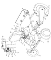
前記シート32は、車体1フレーム、乃至ミッションケース6等に支持させる支持パイプ40に対してシート軸38を回動可能に嵌合支持し、これらシート軸38に設けるロックレバー39を、支持パイプ40側のソケットに係合させて、シート32姿勢を前後に振り替えることができる。このシート32の下側のシートカバー41内側に前記傾斜センサ2を設ける。この傾斜センサ2は、ウエイト42を有するウエイトアーム43をセンサ軸44の周りに左右回動自在に支持させて、車体1の左右傾斜によって回動することにより車体1の左右傾斜角度を検出することができる。このようセンサ軸44は車体1に支持させた支持ブラケット45に対して前後方向水平状に設け、前記ウエイトアーム43と共に操作アーム46を嵌合させて、操作具3によってスプリング47に抗して前後方向へ移動操作可能に設ける。この操作具3、及び操作アーム46をスプリング47によってウエイト42の側へ押圧した状態では、この操作アーム46に設けられたテーパピン48がウエイトアーム43に形成されたピン穴49に係合して一体的に回動する状態になる。このときの形態を自動ローリング位置Aとして、このウエイト42の左右揺動によって車体1の左右傾斜角度を検出して、ローリング制御バルブを連動して、ローリング制御を行うものである。又、操作具3をこのテーパピン48の係合した状態で左右へ移動すると操作アーム46をセンサ軸44の周りに回動することができ、ウエイト42による傾斜角度位置を決めることができる。ここで、操作具3をスプリング47に抗して前側へ操作することによって、操作アーム46のテーパピン48をウエイトアーム43のピン穴49から外し、ローリング位置を一定の状態に固定して手動ローリング位置Bとする。この状態では、ウエイト42が左右に揺動してもローリング制御バルブは作動されないため、ローリング位置はこの傾斜センサ2によって指定された傾斜角度のもとに固定維持されて、作業走行するものである。従って操作具3をシートカバー41に形成のレバーガイド50に沿って左右に回動することによってウエイト42の傾斜角度を変えて車体1の左右傾斜角度を優先的に変更して、この車体1の傾斜姿勢を固定した状態のもとに作業走行することができる。
The
前記昇降機構4は、ハンドル7部に植付レバー51を有し、この植付レバー51を操作することによって、前記ピッチングバルブを作動してピッチングシリンダ13を作動し、車体1を下降、又は上昇すると共に、苗植装置の伝動の苗植クラッチを入り、切りするように連動構成している。このような植付レバー51によりワイヤー52連動のクランクアーム53を車体1フレームのブラケット54に対して回動可能に設け、このクランクアーム53先端部56に回動自在のローラ55を設け、このローラ55を操作アーム46の後面に摺接させてスプリング47に抗して手動ローリング位置Bへ移動操作することができる。植付レバー51を植付位置に操作すると、この操作アーム46を前側の手動ローリング位置Bへ移動し、植付レバー51を非植付位置へ操作すると、自動ローリング位置Aへ切替移動することができる。このように植付レバー51の操作に連動して操作アーム46、及びテーパピン48により、傾斜センサー2のウエイト42との結合、解除を可能に構成している。
The elevating mechanism 4 has a
苗植作業時は、作業者がハンドル7操作しながら車体を走行し、苗供給装置18の苗カップ19コンベア、及び苗植嘴16を伝動して苗植付作用を行わせる。カップ19コンベアの各苗カップ19への苗補給は、作業者がシート32横方向の補助苗載台枠17部から苗を取出しながら行う。このように各苗カップ19に補給された苗は、この苗カップ19が各苗植嘴16の作動する苗供給位置に移動したとき、苗カップ19底部のシャッターが開かれて、下側に位置する苗植嘴16の苗ホッパー31に落下供給する。各苗植嘴16は上昇位置にあって、苗ホッパー31を介して案内する苗を苗植嘴16内に収容保持すると、下降して土壌面に差し込む。この苗植嘴16が土壌面に差し込まれると左右へ開かれて土壌面に植付穴を形成する。この開かれた状態の苗植嘴16は苗を植付穴部に残して上昇し、後続の培土ディスク34の培土作用を行って苗植付姿勢を保持させることができる。上昇した苗植嘴16は、各対向の苗供給位置で次の苗カップ19による苗供給を受けるものである。
At the time of the seedling planting operation, the operator travels the vehicle body while operating the
次に、主として図3、〜図5に基づいて、前記支持ロッド36をメインフレーム8に固定の支持部材57のロッド穴に対して上下動自在に嵌合案内させている。この支持ロッド36は下部の培土ディスク37等の重量によって下動状態にあって、常時苗植付土壌面に圧接して培土する状態にあるが、ハンドル35を操作して、又は、培土ディスク37の接地圧が大きくなるときは、この支持ロッド36が押し上げられる。このとき支持ロッド36の途中に形成の係止溝58部にロックボルト62によって締付け固定されるカラー60を設ける。このカラー60をも該支持部材57のロッド穴63に対して嵌合して上下動して、この下動時にカラー60の下縁部がロッド穴63の上縁部に係止されて、この支持ロッド36や、培土ディスク37等の下動を係止吊持することができる。このカラー60上面に円錐形状のテーパー面59を形成したカラー60を、ロッド穴63に嵌合させて上下動させるため、支持ロッド36の上動時はテーパー面59によってカラー60のロッド穴63に対する嵌合を円滑に行わせる。又、このカラー60がロッド穴63の上側から下動するときはこれらの嵌合位置を変心させて、カラー60の下縁部をロッド穴35縁部を係合させる。このカラー60は、ボルト穴61に螺挿のロックボルト62によって支持ロッド36に対して固定することができる。又、このカラー60は摩耗することによって交換を容易に行うことができる。又、支持ロッド36をタフトライト等の表面硬化処理を行い、カラー60側を摩耗しやすくすることもできる。又、このカラー60の上下移動調節によって苗植付土壌面の高さに適応した培土位置に調節することができる。又、この支持ロッド36の上端部のハンドル35部を後側へ曲げて、前記苗供給装置18、ないしこの上部に載せる苗箱等に対する接触を防止する。又、苗供給装置18の上部に突出させて目視センサーとすることができる。
Next, mainly based on FIGS. 3 to 5, the
次に、主として図6に基づいて、前記後輪12の車軸11を外側へ延出させて、この車軸11部にステップペダル64を設けて、作業者の乗り降りを行い易くするものである。このステップペダル64は車軸11に対して回動自在に嵌合支持して踏付けし易くすることができる。
Next, mainly based on FIG. 6, the
次に、主として図7に基づいて、前記シートカバー41の上側にシート32を前後振替回動可能に設けるが、このシート32を支持するシートベース65の後側部に対してタンクベース66を前後方向へ摺動可能に設ける。このタンクベース66に比較的浅いタンク受け67を支持し、このタンク受け67には灌水用の水タンク68を搭載可能に設ける。水タンク68を左右方向へ拡張させて、しかもタンクベース66を前後方向へ移動調節することによって、水タンク68搭載のスペースを狭くすると共に、重量バランスを取り易くするものである。又、シート32を前後に振替旋回するときは、この水タンク68をも一体にして旋回することができる。又、タンク受け67から水タンク68を外した状態では、このタンク受け67を空トレイ受けとして使用することができる。
Next, mainly based on FIG. 7, the
次に、主として図8に基づいて、前記支持パイプ40とシート軸38との間にトルクスプリング70を設けて、シート32を一定の位置に回動付勢して、作業者の昇降を容易化するものである。トルクスプリング70を支持パイプ40やシート軸38の周りに絞め付けて、シート32の回り止めとするようにすることができる。又、このスプリング70の立ち上げ部を利用してシート32のクッション性を維持させることができる。
Next, mainly based on FIG. 8, a
1 車体
2 傾斜センサ
3 操作具
4 昇降機構
DESCRIPTION OF SYMBOLS 1 Car body 2
Claims (3)
Priority Applications (1)
| Application Number | Priority Date | Filing Date | Title |
|---|---|---|---|
| JP2007151662A JP5119752B2 (en) | 2007-06-07 | 2007-06-07 | Work body |
Applications Claiming Priority (1)
| Application Number | Priority Date | Filing Date | Title |
|---|---|---|---|
| JP2007151662A JP5119752B2 (en) | 2007-06-07 | 2007-06-07 | Work body |
Publications (3)
| Publication Number | Publication Date |
|---|---|
| JP2008301761A JP2008301761A (en) | 2008-12-18 |
| JP2008301761A5 JP2008301761A5 (en) | 2011-09-08 |
| JP5119752B2 true JP5119752B2 (en) | 2013-01-16 |
Family
ID=40231033
Family Applications (1)
| Application Number | Title | Priority Date | Filing Date |
|---|---|---|---|
| JP2007151662A Expired - Fee Related JP5119752B2 (en) | 2007-06-07 | 2007-06-07 | Work body |
Country Status (1)
| Country | Link |
|---|---|
| JP (1) | JP5119752B2 (en) |
Families Citing this family (4)
| Publication number | Priority date | Publication date | Assignee | Title |
|---|---|---|---|---|
| JP5445111B2 (en) * | 2009-12-22 | 2014-03-19 | 井関農機株式会社 | Seedling planting machine |
| JP5728901B2 (en) * | 2010-11-25 | 2015-06-03 | 井関農機株式会社 | Transplanter |
| JP6248922B2 (en) * | 2014-12-24 | 2017-12-20 | 井関農機株式会社 | Transplanter |
| JP6859987B2 (en) * | 2018-07-30 | 2021-04-14 | 井関農機株式会社 | Seedling machine |
Family Cites Families (5)
| Publication number | Priority date | Publication date | Assignee | Title |
|---|---|---|---|---|
| JPS63269905A (en) * | 1987-04-28 | 1988-11-08 | Iseki & Co Ltd | Device for rolling of tractor working machine |
| JP2597432Y2 (en) * | 1993-08-24 | 1999-07-05 | ヤンマー農機株式会社 | Rolling control device for vegetable transplanter |
| JP4422278B2 (en) * | 2000-02-16 | 2010-02-24 | ヤンマー株式会社 | Vegetable transplanter |
| JP4454133B2 (en) * | 2000-10-02 | 2010-04-21 | ヤンマー株式会社 | Vegetable transplanter |
| JP2002209406A (en) * | 2001-01-18 | 2002-07-30 | Iseki & Co Ltd | Apparatus for carrying out rolling control of working machine |
-
2007
- 2007-06-07 JP JP2007151662A patent/JP5119752B2/en not_active Expired - Fee Related
Also Published As
| Publication number | Publication date |
|---|---|
| JP2008301761A (en) | 2008-12-18 |
Similar Documents
| Publication | Publication Date | Title |
|---|---|---|
| JP4835248B2 (en) | Seedling transplanter | |
| JP5600892B2 (en) | Working machine | |
| JP5119752B2 (en) | Work body | |
| JP5045654B2 (en) | Ride type rice transplanter | |
| JP2008301761A5 (en) | ||
| JP2013215149A (en) | Transplanter | |
| JP4726643B2 (en) | Transplanter | |
| JP6196145B2 (en) | Ambulatory transplanter | |
| JP2011045280A (en) | Seedling transplanter | |
| JP5954468B2 (en) | Ride type rice transplanter | |
| JP2010029091A (en) | Seedling planter | |
| JP5641096B2 (en) | Seedling transplanter | |
| JP4998223B2 (en) | Seedling transplanter | |
| JP4862721B2 (en) | Seedling transplanter | |
| JP2007006708A (en) | Transplanter | |
| JP2014030428A (en) | Seedling transplanter | |
| JP5957953B2 (en) | Seedling transplanter | |
| JP4891175B2 (en) | Transplanter | |
| JP2007295816A (en) | Seedling planter | |
| JP2005058085A (en) | Self-traveling walking type vegetable transplanter | |
| JP4796440B2 (en) | Transplanter | |
| JP6900968B2 (en) | Seedling transplanter | |
| JP3719011B2 (en) | Seedling transplanter | |
| JP7115503B2 (en) | transplanter | |
| JP4526491B2 (en) | Transplanter |
Legal Events
| Date | Code | Title | Description |
|---|---|---|---|
| A621 | Written request for application examination |
Free format text: JAPANESE INTERMEDIATE CODE: A621 Effective date: 20100528 |
|
| A521 | Request for written amendment filed |
Free format text: JAPANESE INTERMEDIATE CODE: A523 Effective date: 20110727 |
|
| A977 | Report on retrieval |
Free format text: JAPANESE INTERMEDIATE CODE: A971007 Effective date: 20111228 |
|
| A131 | Notification of reasons for refusal |
Free format text: JAPANESE INTERMEDIATE CODE: A131 Effective date: 20120117 |
|
| A521 | Request for written amendment filed |
Free format text: JAPANESE INTERMEDIATE CODE: A523 Effective date: 20120309 |
|
| TRDD | Decision of grant or rejection written | ||
| A01 | Written decision to grant a patent or to grant a registration (utility model) |
Free format text: JAPANESE INTERMEDIATE CODE: A01 Effective date: 20120925 |
|
| A01 | Written decision to grant a patent or to grant a registration (utility model) |
Free format text: JAPANESE INTERMEDIATE CODE: A01 |
|
| A61 | First payment of annual fees (during grant procedure) |
Free format text: JAPANESE INTERMEDIATE CODE: A61 Effective date: 20121008 |
|
| FPAY | Renewal fee payment (event date is renewal date of database) |
Free format text: PAYMENT UNTIL: 20151102 Year of fee payment: 3 |
|
| R150 | Certificate of patent or registration of utility model |
Free format text: JAPANESE INTERMEDIATE CODE: R150 Ref document number: 5119752 Country of ref document: JP Free format text: JAPANESE INTERMEDIATE CODE: R150 |
|
| LAPS | Cancellation because of no payment of annual fees |