JP5118924B2 - Showcase - Google Patents

Showcase Download PDF

Info

Publication number
JP5118924B2
JP5118924B2 JP2007242408A JP2007242408A JP5118924B2 JP 5118924 B2 JP5118924 B2 JP 5118924B2 JP 2007242408 A JP2007242408 A JP 2007242408A JP 2007242408 A JP2007242408 A JP 2007242408A JP 5118924 B2 JP5118924 B2 JP 5118924B2
Authority
JP
Japan
Prior art keywords
shelf
duct
damper
cold air
back panel
Prior art date
Legal status (The legal status is an assumption and is not a legal conclusion. Google has not performed a legal analysis and makes no representation as to the accuracy of the status listed.)
Expired - Fee Related
Application number
JP2007242408A
Other languages
Japanese (ja)
Other versions
JP2009072283A (en
Inventor
繁 新井
芳朗 石坂
Current Assignee (The listed assignees may be inaccurate. Google has not performed a legal analysis and makes no representation or warranty as to the accuracy of the list.)
Sanyo Electric Co Ltd
Original Assignee
Sanyo Electric Co Ltd
Priority date (The priority date is an assumption and is not a legal conclusion. Google has not performed a legal analysis and makes no representation as to the accuracy of the date listed.)
Filing date
Publication date
Application filed by Sanyo Electric Co Ltd filed Critical Sanyo Electric Co Ltd
Priority to JP2007242408A priority Critical patent/JP5118924B2/en
Publication of JP2009072283A publication Critical patent/JP2009072283A/en
Application granted granted Critical
Publication of JP5118924B2 publication Critical patent/JP5118924B2/en
Expired - Fee Related legal-status Critical Current
Anticipated expiration legal-status Critical

Links

Images

Description

本発明は、断熱壁内に陳列室を構成し、この陳列室内に商品陳列用の棚を架設して成るショーケースに関するものである。   The present invention relates to a showcase in which a display room is formed in a heat insulating wall, and a shelf for displaying merchandise is installed in the display room.

従来よりスーパーマーケットやコンビニエンスストアなどに設置されるショーケースは、断熱壁の内側に間隔を存して設けた仕切板との間にダクトを構成し、仕切板の内側には陳列室を構成すると共に、ダクトには冷却器と送風機を設置し、この冷却器と熱交換した冷気を送風機により、ダクトから陳列室内に吹き出す構成とされている。   Traditionally, showcases installed in supermarkets and convenience stores, etc., form a duct between the heat insulation wall and a partition plate provided with a space inside, and configure a display room inside the partition plate. The duct is provided with a cooler and a blower, and cool air exchanged with the cooler is blown out from the duct into the display room.

この場合、陳列室の開口上縁には冷気吐出口が形成されていると共に、開口下縁には冷気吸込口が形成され、いずれもダクトに連通されている。そして、この開口上縁の冷気吐出口から冷気を吹き出し、エアーカーテンを形成しつつ陳列室内を冷却し、吹き出された冷気は開口下縁の冷気吹出口から吸引するものであった。   In this case, a cold air outlet is formed at the upper edge of the opening of the display chamber, and a cold air inlet is formed at the lower edge of the opening, both of which communicate with the duct. Then, cold air was blown out from the cold air discharge port at the upper edge of the opening to cool the display room while forming an air curtain, and the blown out cold air was sucked from the cold air outlet at the lower edge of the opening.

更に、この陳列室内には、複数段の棚が架設される。棚は、内部に棚ダクト(冷気通路)が構成されており、後端には断熱箱体の背方における背面ダクトと連通するための連通部が形成されている。また、棚の前端には、棚ダクトと連通する冷気吐出口が形成されている。これにより、背面ダクト内を上昇した冷気を連通部を介して棚ダクト内に引き込み、該棚の前端に形成された冷気吐出口より吐出することで、該棚下方の陳列室内を冷却するものであった(例えば特許文献1参照)。   Further, a plurality of shelves are installed in the display room. A shelf duct (cold air passage) is formed inside the shelf, and a communication portion is formed at the rear end for communicating with the rear duct at the back of the heat insulating box. In addition, a cold air discharge port communicating with the shelf duct is formed at the front end of the shelf. As a result, the cool air that has risen in the rear duct is drawn into the shelf duct via the communicating portion, and discharged from the cool air discharge port formed at the front end of the shelf, thereby cooling the display chamber below the shelf. (For example, see Patent Document 1).

ここで、各棚ダクトの上面には、ダンパー部材が取り付けられており、当該ダンパー部材は、棚ダクトの下側に臨む操作部と、棚ダクトにダンパー部材を下方から螺合する化粧ビスを有している。これにより、陳列室内を異なる二温度帯、例えば、常温と冷却温度、若しくは、棚上面にヒータを有する場合には加温と冷却温度として使用する際には、それより上側の棚上を常温若しくは加温として使用する棚に設けられたダンパー部材を背面ダクト内に進出させて、当該ダンパー部材により背面ダクトを上下に区画する。   Here, a damper member is attached to the upper surface of each shelf duct, and the damper member has an operation unit facing the lower side of the shelf duct and a cosmetic screw for screwing the damper member into the shelf duct from below. is doing. Accordingly, when the display room is used in two different temperature zones, for example, normal temperature and cooling temperature, or when the heater is provided on the top surface of the shelf, when the heating and cooling temperature is used, A damper member provided on a shelf used for heating is advanced into the rear duct, and the rear duct is partitioned vertically by the damper member.

これにより、背面ダクトを上昇する冷気は、ダンパー部材により、棚ダクト内に案内され、当該棚ダクトより下側の陳列室内を冷却する。他方、ダンパー部材により、当該棚より上側には、冷気が供給されないことから、当該棚より上側の陳列室内を常温又は加温して使用する。
2004−261502号公報
Thus, the cool air rising up the back duct is guided into the shelf duct by the damper member, and cools the display chamber below the shelf duct. On the other hand, since the damper member does not supply cool air to the upper side of the shelf, the display room above the shelf is used at room temperature or heated.
No. 2004-261502

従来のショーケースにおいて、ダンパー部材を背面ダクト側に進出、若しくは、陳列室内に後退させる作業を行う際には、まず、ダンパー部材を棚ダクトに固定している化粧ビスを緩め、操作部を持って前後に摺動させることにより行う。しかしながら、当該化粧ビスやダンパー部材の操作部は、棚の下側に設けられているため、化粧ビスの位置や操作部の位置を視認しながら操作することは困難であり、手探りにて化粧ビスや操作部の位置を確認しながらの作業を強いられていた。   In a conventional showcase, when the damper member is advanced to the rear duct side or moved back into the display room, first the loosening screw that fixes the damper member to the shelf duct is loosened and the operation part is held. This is done by sliding back and forth. However, since the operation part of the cosmetic screw and the damper member is provided on the lower side of the shelf, it is difficult to operate while visually checking the position of the cosmetic screw and the position of the operation part. And was forced to work while checking the position of the operation unit.

また、この種のショーケースに設けられる棚装置は、棚板全体を前後に摺動可能とするスライド棚が採用されていることが多く、棚装置自体の構造が複雑であり、また、重量も嵩んでいる。そのため、当該棚装置を陳列室内に保持するブラケットや支柱の強度向上を図らなければ成らず、生産性の面からも、棚装置自体の構造を簡素化し、且つ、軽量化することが望まれている。   In addition, the shelf device provided in this type of showcase often employs a slide shelf that allows the entire shelf board to slide back and forth, and the structure of the shelf device itself is complicated, and the weight is also high. It is bulky. For this reason, it is necessary to improve the strength of the brackets and support columns for holding the shelf device in the display room, and from the viewpoint of productivity, it is desirable to simplify the structure of the shelf device itself and reduce the weight. Yes.

そこで、本発明は従来の技術的課題を解決するためになされたものであり、ダンパーの操作により陳列室内に二温度帯を形成して使用するショーケースであって、当該ダンパー部材の操作を容易とすることができると共に、棚装置自体の構造を簡素化することができるショーケースを提供する。   Therefore, the present invention has been made to solve the conventional technical problem, and is a showcase that is used by forming a two-temperature zone in the display chamber by operating the damper, and the operation of the damper member is easy. And a showcase capable of simplifying the structure of the shelf device itself.

本発明のショーケースは、断熱壁内に前面が開口する陳列室を構成し、該陳列室内に商品陳列用の棚を架設して成るものであって、陳列室の背面に位置し、断熱壁との間に冷気が上昇する背面ダクトを構成するための背面パネルと、棚に設けられ、後端の連通部にて背面ダクトに連通すると共に、前端に冷気吐出口が形成された棚ダクトと、連通部の上側において、背面ダクトを閉塞するためのダンパーとを備え、該ダンパーは、背面パネルに形成された透孔に移動自在に保持されて背面ダクトを閉塞するための閉塞板部と、背面パネルに着脱自在に固定するための固定具とを有し、背面パネルに固定されずに手前側に引き出された状態で、閉塞板部は背面パネルの透孔縁部に係合して当該ダンパーは背面パネルに保持され、背面ダクトは開放されると共に、奥側に押し込まれ、固定具により背面パネルに固定された状態で、閉塞板部は背面ダクトを閉塞することを特徴とする。   The showcase of the present invention comprises a display room having an open front surface in a heat insulating wall, and a shelf for displaying merchandise is installed in the display room, and is located on the back surface of the display room. A rear panel for constructing a rear duct in which cool air rises between the rear duct, a shelf duct provided on the shelf, communicated with the rear duct at the rear end communicating portion, and formed with a cold air outlet at the front end; A damper for closing the back duct on the upper side of the communication part, the damper being movably held in a through hole formed in the back panel, and a closing plate part for closing the back duct; A closure for detachably fixing to the back panel, and in a state of being pulled out to the front side without being fixed to the back panel, the closing plate portion engages with the through hole edge of the back panel and The damper is held on the rear panel and the rear duct is open. While being, pushed to the rear side, in the state of being fixed to the back panel by fasteners, the closing plate part, characterized in that for closing the rear duct.

請求項2の発明のショーケースは、上記発明において、閉塞板部の後端は、透孔の幅よりも幅広とされていることを特徴とする。   The showcase of the invention of claim 2 is characterized in that, in the above invention, the rear end of the blocking plate portion is wider than the width of the through hole.

請求項3の発明のショーケースは、上記発明において、閉塞板部の後端は上側に折曲されており、ダンパーが手前側に位置した状態で、背面パネル後面に沿うことを特徴とする。   A showcase according to a third aspect of the present invention is characterized in that, in the above invention, the rear end of the closing plate portion is bent upward, and the rear panel is along the rear surface of the rear panel in a state where the damper is positioned on the near side.

本発明によれば、断熱壁内に前面が開口する陳列室を構成し、該陳列室内に商品陳列用の棚を架設して成るショーケースにおいて、陳列室の背面に位置し、断熱壁との間に冷気が上昇する背面ダクトを構成するための背面パネルと、棚に設けられ、後端の連通部にて背面ダクトに連通すると共に、前端に冷気吐出口が形成された棚ダクトと、連通部の上側において、背面ダクトを閉塞するためのダンパーとを備え、該ダンパーは、背面パネルに形成された透孔に移動自在に保持されて背面ダクトを閉塞するための閉塞板部と、背面パネルに着脱自在に固定するための固定具とを有し、背面パネルに固定されずに手前側に引き出された状態で、閉塞板部は背面パネルの透孔縁部に係合して当該ダンパーは背面パネルに保持され、背面ダクトは開放されると共に、奥側に押し込まれ、固定具により背面パネルに固定された状態で、閉塞板部は背面ダクトを閉塞するので、背面パネルに保持されるダンパーを直接視認しながら、当該ダンパーにより背面ダクトを開放する操作及び閉塞する操作を行うことが可能となる。   According to the present invention, in a showcase in which a display room having a front surface opened in a heat insulating wall and a shelf for displaying merchandise is constructed in the display room, the display case is located on the back surface of the display room, A rear panel for forming a rear duct in which cool air rises, and a shelf duct that is provided on the shelf and communicates with the rear duct at the rear end communication portion and has a cold air discharge port formed at the front end, and communication A damper for closing the back duct on the upper side of the part, the damper being movably held in a through hole formed in the back panel, and a closing plate part for closing the back duct, and the back panel And a fixing tool for detachably fixing to the rear panel, the closing plate portion is engaged with the through hole edge of the rear panel in a state where it is pulled out to the near side without being fixed to the rear panel, and the damper is It is held by the back panel and the back duct is open. In addition, the closing plate portion closes the rear duct while being pushed into the back side and fixed to the rear panel by a fixture, so that the damper held on the rear panel can be directly viewed while It is possible to perform an operation of opening and closing the duct.

これにより、従来のように手探りにてダンパーの操作を行う場合に比して、容易に、且つ、確実にダンパー操作を行うことが可能となり、利便性の向上を図ることが可能となる。特に、本発明によれば、ダンパーは、背面パネルに形成された透孔に保持されるものであることから、棚に設けられる場合に比して、当該棚自体の構造を簡素化することが可能となり、生産性の向上や、棚自体の重量を軽量化することができる。   Accordingly, it is possible to easily and surely perform the damper operation as compared with the conventional case where the damper is operated by groping, and the convenience can be improved. In particular, according to the present invention, since the damper is held in the through hole formed in the back panel, the structure of the shelf itself can be simplified as compared with the case where the damper is provided on the shelf. Thus, productivity can be improved and the weight of the shelf itself can be reduced.

また、ダンパーは、背面パネルに固定されずに手前側に引き出された状態では、閉塞板部は背面パネルの透孔縁部に係合して当該ダンパーは背面パネルに保持され、背面ダクトを開放するため、簡素な構造にて、背面ダクトを開放した状態を維持することが可能となる。   When the damper is pulled out to the near side without being fixed to the back panel, the closing plate engages with the edge of the through hole of the back panel, the damper is held by the back panel, and the back duct is opened. Therefore, it is possible to maintain a state where the rear duct is opened with a simple structure.

更に、ダンパーは、奥側に押し込まれ、固定具により背面パネルに固定された状態で、閉塞板部は背面ダクトを閉塞するため、固定具により安定して閉塞板部による背面ダクトの閉塞状態を維持することが可能となる。   Furthermore, since the damper is pushed into the back side and is fixed to the rear panel by the fixture, the closing plate portion closes the rear duct, so that the closing plate stably blocks the rear duct by the fixture. Can be maintained.

請求項2の発明によれば、上記発明において、閉塞板部の後端は、透孔の幅よりも幅広とされているので、上述したような背面パネルに固定されずに手前側に引き出された状態において、透孔の幅よりも幅広に形成された閉塞板部の後端が当該背面パネルの透孔から脱落してしまう不都合を回避することができ、安定した保持状態を維持することが可能となる。   According to the invention of claim 2, in the above invention, since the rear end of the blocking plate portion is wider than the width of the through hole, it is pulled out to the near side without being fixed to the back panel as described above. In this state, it is possible to avoid the inconvenience that the rear end of the closing plate portion formed wider than the width of the through hole falls off from the through hole of the rear panel, and to maintain a stable holding state. It becomes possible.

請求項3の発明によれば、上記発明において、閉塞板部の後端は上側に折曲されており、ダンパーが手前側に位置した状態で、背面パネル後面に沿うことから、手前側に引き出された状態のダンパーを後端が背面パネル後面に沿った状態で透孔縁部に係支させることができ、ダンパー全体をより背面パネルに沿わせた状態で保持することができる。これにより、ダンパーが背面パネルから大きく前方に突出することによって、陳列室内の商品陳列の邪魔となる不都合を抑制することが可能となる。   According to the invention of claim 3, in the above invention, the rear end of the blocking plate portion is bent upward, and the damper is positioned on the near side, and is along the rear surface of the rear panel, so that it is pulled out to the near side. The damper in such a state can be engaged with the edge of the through hole in a state where the rear end is along the rear surface of the back panel, and the entire damper can be held in a state where it is further along the back panel. Thereby, it becomes possible to suppress the inconvenience which obstructs the display of goods in the display room by the damper projecting largely forward from the back panel.

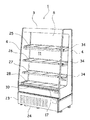
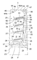
以下、本発明の実施形態を図面に基づき詳細に説明する。図1は本発明を適用したショーケース1の斜視図、図2はショーケース1の縦断側面図(最上段の棚25に棚ダクト部材50を取り付けた状態)を示している。   Hereinafter, embodiments of the present invention will be described in detail with reference to the drawings. FIG. 1 is a perspective view of a showcase 1 to which the present invention is applied, and FIG. 2 is a vertical side view of the showcase 1 (a state in which a shelf duct member 50 is attached to the uppermost shelf 25).

ショーケース1は前面に開口する断面略コ字状の断熱壁3と、その両側に取り付けられた側板4によって本体5が構成されており、この断熱壁3の内側には間隔を存して背面に背面パネル6が配設され、この背面パネル6と断熱壁3間に背面ダクト9が形成されている。尚、背面パネル6の詳細については後述する。また、背面パネル6の下端には、前方に延在するデックパン10が設けられており、これら背面パネル6、デックパン10及び断熱壁3の天井部3Aの内側に陳列室11が構成されている。そして、デックパン10の下方には背面ダクト9に連通して下部ダクト14が構成されている。   The showcase 1 includes a heat insulating wall 3 having a substantially U-shaped cross section that opens to the front and side plates 4 attached to both sides thereof, and a main body 5 is formed. A rear panel 6 is disposed on the rear panel 6, and a rear duct 9 is formed between the rear panel 6 and the heat insulating wall 3. Details of the back panel 6 will be described later. Further, a deck pan 10 extending forward is provided at the lower end of the back panel 6, and a display chamber 11 is configured inside the back panel 6, the deck pan 10, and the ceiling portion 3 </ b> A of the heat insulating wall 3. A lower duct 14 is formed below the deck pan 10 so as to communicate with the rear duct 9.

この下部ダクト14の前端は陳列室11の前面開口下縁に位置すると共に、複数のスリットから成る冷気吸込口17に連通している。デックパン10の下方の下部ダクト14内には冷気送給用の送風機7が配設され、陳列室11の背面ダクト9内には冷却装置の冷凍サイクルを構成する冷却器15が縦設されている。   The front end of the lower duct 14 is located at the lower edge of the front opening of the display chamber 11 and communicates with the cold air inlet 17 formed of a plurality of slits. A blower 7 for supplying cold air is disposed in a lower duct 14 below the deck pan 10, and a cooler 15 constituting a refrigeration cycle of a cooling device is vertically installed in a rear duct 9 of the display chamber 11. .

断熱壁3の下側には機械室19が構成されており、この機械室19内には前記冷却器15と共に冷却装置の冷凍サイクルを構成する圧縮機や凝縮器、凝縮器用送風機が設置されると共に、電源や制御基板を収納した電装箱も配設される。断熱壁3の背方には当該断熱壁3の背面と所定の間隔を存して鋼板製の背面板20が取り付けられており、この背面板20と断熱壁3間には排気用ダクト21が構成されている。   A machine room 19 is formed below the heat insulating wall 3, and a compressor, a condenser, and a condenser blower constituting a refrigeration cycle of the cooling device together with the cooler 15 are installed in the machine room 19. In addition, an electrical box that houses a power supply and a control board is also provided. A back plate 20 made of steel plate is attached to the back of the heat insulating wall 3 with a predetermined distance from the back surface of the heat insulating wall 3, and an exhaust duct 21 is provided between the back plate 20 and the heat insulating wall 3. It is configured.

この排気用ダクト21の下端は機械室19の後部に開口して連通すると共に、上端はショーケース1上方に開放している。尚、23は機械室19の前面を開閉自在に閉じるパネルである。24は機械室19内下部に設けられた蒸発皿であり、図示しないドレンホースを介して冷却器15からのドレン水(露水や除霜水など)が流入し、貯留されるものである。   The lower end of the exhaust duct 21 opens and communicates with the rear portion of the machine room 19, and the upper end is open above the showcase 1. Reference numeral 23 denotes a panel for closing the front of the machine room 19 so as to be freely opened and closed. Reference numeral 24 denotes an evaporating dish provided in the lower part of the machine room 19, and drain water (dew water, defrost water, etc.) from the cooler 15 flows in through a drain hose (not shown) and is stored.

陳列室11内には棚が複数段、本実施例では上から順に、25、26、27、28が四段架設されている。ここで、各棚25、26、27、28は、略同一の構成とされているため、棚25を例に挙げて図3乃至図7を参照して当該棚25及び棚25に取り付けられる棚ダクト部材50について説明する。図3は棚25の縦断正面図、図4は図3の部分拡大図、図5は棚ダクト部材50の取付状態を示す陳列室11側からみた側面図、図6は棚25及び棚ダクト部材50の一部切欠縦断側面図、図7はダクト部材50の底面図をそれぞれ示している。   In the display room 11, a plurality of shelves are provided, and in this embodiment, 25, 26, 27, and 28 are arranged in four stages in order from the top. Here, since the shelves 25, 26, 27, and 28 have substantially the same configuration, the shelves 25 and the shelves attached to the shelves 25 with reference to FIGS. The duct member 50 will be described. 3 is a longitudinal front view of the shelf 25, FIG. 4 is a partially enlarged view of FIG. 3, FIG. 5 is a side view of the shelf duct member 50 as viewed from the display chamber 11, and FIG. 6 is the shelf 25 and the shelf duct member. FIG. 7 is a bottom view of the duct member 50. FIG.

棚25は前側が低く傾斜して架設されており、これにより、最も手前側の商品が取り出されると、その列の後方の商品が順次前方に移動する構成とされている。また、棚25はブラケット30と図示しない支柱に形成された係合孔との係合により着脱自在の構成とされている。更に、棚25はブラケット30に対してそれぞれ前方に引出自在とされ、陳列室11内に押し込まれて保持された状態と、商品補充時に前面開口から手前側に引き出された状態とに保持可能とされている。   The shelves 25 are constructed so that the front side is inclined at a low angle, and as a result, when the foremost product is taken out, the products in the rear of the row sequentially move forward. Further, the shelf 25 is configured to be detachable by engagement between the bracket 30 and an engagement hole formed in a post (not shown). Furthermore, the shelf 25 can be pulled out forward with respect to the bracket 30 and can be held in a state where it is pushed into the display chamber 11 and held, and in a state where it is pulled out from the front opening when the product is refilled. Has been.

棚25は、前後に延在する一対の枠部材32、32とこの枠部材32上に取り付けられ、商品を載置するための棚板33等から構成されている。そして、この棚板33は金属板から成り、その商品載置面の裏側には加温用ヒータH(電気ヒータ。図4参照)が取り付けられている。加温使用時にはこの加温用ヒータHが発熱して棚板33上の商品を加熱保温する。   The shelf 25 includes a pair of frame members 32, 32 extending in the front-rear direction and a shelf plate 33 for mounting products on the frame member 32. And this shelf board 33 consists of a metal plate, and the heater H for heating (electric heater. Refer FIG. 4) is attached to the back side of the goods mounting surface. When heating is used, the heating heater H generates heat and heats and keeps the product on the shelf board 33.

他方、前記ブラケット30の後端には係合爪29が形成されており、この係合爪29を陳列室11内の左右に上下に渡って取り付けられた図示しない支柱の係合孔に係脱自在に係合させることで、ブラケット30は陳列室11内に所定の高さの位置に左右一対ずつ取り付けられる。そして、これら一対のブラケット30、30それぞれの外面にスライドレール31の固定側31Aが前後に渡って取り付けられ、左右で一対を成す。   On the other hand, an engagement claw 29 is formed at the rear end of the bracket 30, and the engagement claw 29 is engaged with and disengaged from an engagement hole of a column (not shown) attached to the left and right in the display chamber 11. By freely engaging, the brackets 30 are attached to the display chamber 11 at a predetermined height in pairs. And the fixed side 31A of the slide rail 31 is attached to the outer surface of each of these pair of brackets 30 and 30 over the front and back, and it makes a pair by right and left.

また、枠部材32は、ブラケット30の外側において下方に折曲され、降下辺34が形成されており、この降下辺34、34の内側に前記スライドレール31、31の可動側31Bがそれぞれ取り付けられる。これにより、棚板33は枠部材32の降下辺34に取り付けられるスライドレール31の可動側31Bと、ブラケット30に取り付けられるスライドレール31の固定側31Aによって、ブラケット30、30に対し前後に摺動自在とされる。   Further, the frame member 32 is bent downward on the outside of the bracket 30 to form a descending side 34, and the movable side 31B of the slide rails 31 and 31 is attached to the inside of the descending sides 34 and 34, respectively. . Accordingly, the shelf board 33 slides back and forth with respect to the brackets 30 and 30 by the movable side 31B of the slide rail 31 attached to the descending side 34 of the frame member 32 and the fixed side 31A of the slide rail 31 attached to the bracket 30. It is made free.

そして、ブラケット30、30の内側には、棚板33の下側に位置して棚ダクト部材50が着脱自在に取り付けられる。本実施例における棚ダクト部材50は、内部中空の矩形状を呈しており、当該前端は、棚板33の前端よりも前方まで延在していると共に、当該後端は、棚板33の後端よりも後方まで延在している。そして、棚ダクト部材50の後面(後端)は、後ろ向きに開口した連通部51が形成され、下面前端には左右方向に延在して下向きに開口した中間冷気吐出口52が形成されている。   And the shelf duct member 50 is detachably attached to the inner side of the brackets 30 and 30 so as to be located below the shelf plate 33. The shelf duct member 50 in the present embodiment has an internal hollow rectangular shape, the front end extends to the front of the front end of the shelf plate 33, and the rear end is the rear of the shelf plate 33. It extends to the rear rather than the end. The rear surface (rear end) of the shelf duct member 50 is formed with a communication portion 51 that opens backward, and the intermediate cold air discharge port 52 that extends in the left-right direction and opens downward is formed at the front end of the lower surface. .

ここで、棚ダクト部材50の後端に形成される連通部51は、棚25の下側に位置して当該棚25の背面に設けられる背面パネル6前面に当接して設けられるため、棚25の傾斜角度に応じて上端が下端よりも後方に延在して形成される。他方、棚25に取り付けられる棚ダクト部材50の連通部51に対応する位置の背面パネル6には、左右に渡って背面ダクト9と、棚ダクト部材50内に形成される棚ダクト53とを連通するための連通孔54が形成されている。なお、当該連通孔54は、棚25に取り付けられる棚ダクト部材50に対応する位置のみならず、本実施例では、当該棚25の下側に架設される棚26に取り付けられる棚ダクト部材50に対応する位置にも形成されているものとする。なお、他の棚27、28についても同様に連通孔54を形成しても良い。   Here, since the communication portion 51 formed at the rear end of the shelf duct member 50 is provided in contact with the front surface of the back panel 6 provided on the back side of the shelf 25 located below the shelf 25, the shelf 25. In accordance with the inclination angle, the upper end extends rearward from the lower end. On the other hand, the rear panel 9 at a position corresponding to the communication portion 51 of the shelf duct member 50 attached to the shelf 25 communicates with the rear duct 9 and the shelf duct 53 formed in the shelf duct member 50 across the left and right. A communication hole 54 is formed for this purpose. Note that the communication hole 54 is provided not only at a position corresponding to the shelf duct member 50 attached to the shelf 25 but also in the shelf duct member 50 attached to the shelf 26 installed under the shelf 25 in the present embodiment. It is assumed that they are also formed at corresponding positions. Similarly, the communication holes 54 may be formed for the other shelves 27 and 28.

そして、この棚ダクト部材50の後部両側面には、外方に向けて所定寸法だけ延在して形成される係支棒55、55が取り付けられている。本実施例では、当該係支棒55の端部は、頭部55Aが形成されている。また、棚ダクト部材50の前部であって、中間冷気吐出口52よりも後方両側面には、断面略L字状の取付部材56が取り付けられている。   Further, on both side surfaces of the rear portion of the shelf duct member 50, supporting rods 55, 55 formed to extend outward by a predetermined dimension are attached. In the present embodiment, a head portion 55 </ b> A is formed at the end of the support rod 55. Also, attachment members 56 having a substantially L-shaped cross section are attached to the front part of the shelf duct member 50 and on both side surfaces behind the intermediate cold air discharge port 52.

この取付部材56の側面は、棚ダクト部材50側面に当接してネジ止めにより固定されると共に、取付部材56の上面には、詳細は後述するブラケット30に固定される保持片60の上端部を挿入して係合するための係合孔56Aが形成されている。   The side surface of the mounting member 56 abuts the side surface of the shelf duct member 50 and is fixed by screwing. The upper surface of the mounting member 56 has an upper end portion of a holding piece 60 fixed to the bracket 30 to be described later in detail. An engagement hole 56A for insertion and engagement is formed.

一方、当該棚ダクト部材50が取り付けられるブラケット30には、対向するブラケット30、30の上端に渡って、左右両端が下方に略直角に折曲された保持板58が棚板33の下面とは所定間隔を存してネジなどにより固定されている。そして、この保持板58の下面両側部には、それぞれブラケット30と所定間隔を存して断面略L字状の吊下部材59が取り付けられている。   On the other hand, the bracket 30 to which the shelf duct member 50 is attached has a holding plate 58 whose left and right ends are bent downward at substantially right angles across the upper ends of the opposing brackets 30, 30. It is fixed with screws or the like at a predetermined interval. A suspension member 59 having a substantially L-shaped cross section is attached to both sides of the lower surface of the holding plate 58 with a predetermined distance from the bracket 30.

この吊下部材59の上面は、保持板58の下面に当接してネジ止めにより固定されると共に、当該上面端部から垂下して形成される側面には、前端から後方に向けて切り欠かれた係止部59Aが形成されている。当該係止部59Aは、前記棚ダクト部材50に設けられた両端の係支棒55を挿入して保持するものである。従って、当該係止部59Aの下縁前端は、少許上方に傾斜して、容易に係支棒55が前端より脱落しない構成とされていることが望ましい。   The upper surface of the suspension member 59 abuts the lower surface of the holding plate 58 and is fixed by screwing, and a side surface formed by hanging from the end of the upper surface is notched rearward from the front end. A locking portion 59A is formed. The locking portion 59A is for inserting and holding the support rods 55 at both ends provided in the shelf duct member 50. Therefore, it is desirable that the lower edge front end of the locking portion 59A is inclined slightly upward so that the support bar 55 does not easily fall off from the front end.

他方、ブラケット30、30の内面前部であって、棚ダクト部材50がブラケット30に取り付けられた状態で、棚ダクト部材50に設けられる取付部材56が対応する位置には、前記保持片60が取り付けられている。この保持片60は、断面略クランク状に形成されており、下方に向けて延在する側面は、ブラケット30内面に当接してネジ止めにより固定されると共に、上方に向けて延在する側面は、棚ダクト部材50側に配される。   On the other hand, the holding piece 60 is located at a position corresponding to the attachment member 56 provided on the shelf duct member 50 in the state where the shelf duct member 50 is attached to the bracket 30 on the inner surface front part of the brackets 30 and 30. It is attached. The holding piece 60 is formed in a substantially crank shape in cross section, and the side surface extending downward is abutted against the inner surface of the bracket 30 and fixed by screwing, and the side surface extending upward is It is arranged on the shelf duct member 50 side.

係る構成により、棚ダクト部材50を棚25下方に取り付ける際には、まず棚ダクト部材50の後部両側面に設けられる係支棒55、55を、棚25が架設されるブラケット30、30に設けられる吊下部材59の係止部59A前端より挿入し、当該係止部59Aの下縁に保持させる。その後、棚ダクト部材50の前部両側面に設けられる取付部材56の係合孔56Aに対向するブラケット30に取り付けられた保持片60上端を挿入し、当該保持片60上面に棚ダクト部材50の取付部材56を載置し保持させる。   With this configuration, when attaching the shelf duct member 50 to the lower side of the shelf 25, first, the support rods 55 and 55 provided on both side surfaces of the rear portion of the shelf duct member 50 are provided on the brackets 30 and 30 on which the shelf 25 is installed. It inserts from the front end of the latching | locking part 59A of the hanging member 59, and is hold | maintained on the lower edge of the said latching | locking part 59A. Thereafter, the upper end of the holding piece 60 attached to the bracket 30 facing the engagement hole 56A of the attachment member 56 provided on both side surfaces of the front portion of the shelf duct member 50 is inserted, and the upper side of the shelf duct member 50 is inserted into the upper surface of the holding piece 60. The mounting member 56 is placed and held.

これにより、棚ダクト部材50を棚25が架設されるブラケット30、30に取り付けられる。この状態で、棚ダクト部材50の背方に対応する背面パネル6には、背面ダクト9内と連通可能とする連通孔54が形成されているため、背面パネル6の前面に当接して設けられる棚ダクト部材50の連通部51を介して背面ダクト9内を上昇する冷気を棚ダクト53内に流入させることができる。棚ダクト部材50の前端には、下向きに開口された中間冷気吐出口52が形成されていることから、当該タクト53内の冷気を中間冷気吐出口52より下方に向けて吐出させることができる。   Thereby, the shelf duct member 50 is attached to the brackets 30 and 30 on which the shelf 25 is installed. In this state, the rear panel 6 corresponding to the back of the shelf duct member 50 is formed with a communication hole 54 that allows communication with the interior of the rear duct 9, and is provided in contact with the front surface of the rear panel 6. Cold air rising in the rear duct 9 can be caused to flow into the shelf duct 53 through the communication portion 51 of the shelf duct member 50. Since the intermediate cold air discharge port 52 opened downward is formed at the front end of the shelf duct member 50, the cold air in the tact 53 can be discharged downward from the intermediate cold air discharge port 52.

ここで、上述したように棚ダクト部材50は、棚25の棚板33下方に位置して当該棚25が設けられるブラケット30、30間に挿入により容易に係止可能とする吊下部材59と係支棒55、及び、保持片60と取付部材56により取り付けられるため、着脱容易とされる。   Here, as described above, the shelf duct member 50 is positioned below the shelf plate 33 of the shelf 25 and can be easily locked between the brackets 30 and 30 on which the shelf 25 is provided, Since it is attached by the support bar 55, the holding piece 60, and the attachment member 56, it is easy to attach and detach.

また、当該棚ダクト部材50を取り付けるための吊下部材59や保持片60は、他の棚26、27、28にも同様に設けられていることから、選択的に当該棚ダクト部材50を何れかの棚に容易に取り付けることが可能となる。   In addition, since the suspension member 59 and the holding piece 60 for attaching the shelf duct member 50 are provided in the same manner on the other shelves 26, 27, and 28, any of the shelf duct members 50 can be selectively used. It can be easily attached to the shelf.

次に、図8乃至図10を参照して、ショーケース1上部の構成について説明する。図8はショーケース1上部拡大縦断側面図、図9は図8における開閉パネル部43手前側に回動させた状態の上部拡大縦断側面図、図10は冷気吐出口部材44を後方からみた部分拡大図をそれぞれ示している。   Next, the configuration of the upper part of the showcase 1 will be described with reference to FIGS. FIG. 8 is an enlarged vertical side view of the upper part of the showcase 1, FIG. 9 is an enlarged vertical side view of the upper part in a state of being rotated to the front side of the opening / closing panel 43 in FIG. 8, and FIG. Each enlarged view is shown.

背面パネル6の上端には、当該背面パネル6の一部を構成する開閉パネル部43が取り付けられている。この開閉パネル部43は、ヒンジ部材により、下縁を中心として手前側に回動自在に取り付けられており、常時上側方向に付勢されている。そして、この開閉パネル部43の上端は、前側に所定角度にて折曲された当接面43Aが形成されており、当該当接面43Aには、図示しないネジ止め用の孔が形成されている。   At the upper end of the back panel 6, an open / close panel portion 43 constituting a part of the back panel 6 is attached. The open / close panel portion 43 is pivotally attached to the front side with a hinge member as a center, and is always urged upward. The upper end of the opening / closing panel 43 is formed with a contact surface 43A bent at a predetermined angle on the front side, and a screw fixing hole (not shown) is formed on the contact surface 43A. Yes.

他方、断熱壁3の前面開口上縁には、左右に渡って冷気吐出部材44が設けられている。当該冷気吐出部材44は、前下部に整流部材としてのハニカム45が取り付けられており、当該冷気吐出部材44の後端部には、全幅に渡って複数の冷気導入口44Bが形成されている。なお、当該冷気導入口44Bの外周縁には、シール材が設けられていても良い。   On the other hand, a cold air discharge member 44 is provided at the upper edge of the front opening of the heat insulating wall 3 from the left and right. The cold air discharge member 44 has a honeycomb 45 as a rectifying member attached to the front lower portion, and a plurality of cold air inlets 44B are formed at the rear end of the cold air discharge member 44 over the entire width. Note that a sealing material may be provided on the outer peripheral edge of the cold air inlet 44B.

そして、この冷気吐出部材44の後側には、陳列室11の天井部3A下側に位置して上記棚ダクト部材50が着脱自在に取付可能とされている。具体的には、冷気吐出部材44の後側両側部に、側板4と所定間隔を存して断面略L字状の吊下部材46、46が取り付けられている。   The shelf duct member 50 is detachably attached to the rear side of the cool air discharge member 44 and located below the ceiling portion 3A of the display chamber 11. Specifically, suspension members 46 and 46 having a substantially L-shaped cross section are attached to both sides of the cool air discharge member 44 at a predetermined interval from the side plate 4.

この吊下部材46の上面は、断熱壁3の天井部3A下面に当接してネジ止めにより固定されると共に、当該上面端部から垂下して形成される側面には、後端から前方に向けて切り欠かれた係止部46Aが形成されている。当該係止部46Aは、前記棚ダクト部材50に設けられた両端の係支棒55を挿入して保持するものである。従って、当該係止部46Aの下縁後端は、少許上方に傾斜して、容易に係支棒55が後端より脱落しない構成とされていることが望ましい。   The upper surface of the suspending member 46 abuts the lower surface of the ceiling portion 3A of the heat insulating wall 3 and is fixed by screwing. The side surface formed by hanging from the upper surface end portion is directed forward from the rear end. A locking portion 46A cut out is formed. The engaging portion 46A is for inserting and holding the supporting rods 55 at both ends provided in the shelf duct member 50. Therefore, it is desirable that the rear end of the lower edge of the locking portion 46A is inclined slightly upward so that the support bar 55 does not easily fall off from the rear end.

他方、背面ダクト9上部であって、断熱壁3の背面3Bの前面両側部には、断面略L字状の保持部材47が取り付けられている。この保持部材47は側面が断熱壁背面3Bに当接してネジ止めにより固定されると共に、当該側面上端が前方に折曲して形成される上面47Aは、棚ダクト部材50の連通部51が設けられている側の端部を保持可能とされている。そして、当該上面47Aは、前端が少許下方に傾斜して形成されている。   On the other hand, holding members 47 having a substantially L-shaped cross section are attached to the upper side of the rear duct 9 and on both sides of the front surface of the rear surface 3B of the heat insulating wall 3. The holding member 47 has a side surface abutting against the heat insulating wall back surface 3B and fixed by screwing, and an upper surface 47A formed by bending the upper end of the side surface forward is provided with the communication portion 51 of the shelf duct member 50. It is possible to hold the end portion on the side that is provided. The upper surface 47A is formed such that the front end is inclined slightly downward.

係る構成により、棚ダクト部材50を陳列室11の天井部3A下側に取り付ける際には、まず何れかの棚25・・・に取り付けられている棚ダクト部材50を取り外し、当該棚ダクト部材50の前後を反転させる。そして、背面パネル6上端を構成する開閉パネル部43をヒンジ部材42を中心として手前側に回動させて、棚ダクト部材50の連通部51が設けられる側の端部を背面ダクト9内に挿入し、当該背面ダクト9上部に設けられる保持部47、47の上面47A、47Aに載置する。その後、中間冷気吐出口52が形成される側の両側面に設けられる係支棒55、55を、天井部3Aの前部に設けられる吊下部材46の係止部46A後端より挿入し、当該係止部59Aの下縁に保持させる。   With this configuration, when the shelf duct member 50 is attached to the lower side of the ceiling portion 3A of the display chamber 11, the shelf duct member 50 attached to any one of the shelves 25 is first removed, and the shelf duct member 50 is removed. Reverse the front and back of. Then, the open / close panel portion 43 constituting the upper end of the back panel 6 is rotated to the near side about the hinge member 42, and the end portion of the shelf duct member 50 on the side where the communication portion 51 is provided is inserted into the back duct 9. And it mounts on the upper surfaces 47A and 47A of the holding | maintenance parts 47 and 47 provided in the said back surface duct 9 upper part. Thereafter, the support rods 55, 55 provided on both side surfaces on the side where the intermediate cold air discharge port 52 is formed are inserted from the rear end of the locking portion 46A of the suspension member 46 provided in the front portion of the ceiling portion 3A, It is held at the lower edge of the locking portion 59A.

この状態で、背面パネル6上端を構成する開閉パネル部43はヒンジ部材42の付勢力によって上方に付勢されているため、当該開閉パネル部43の当接面43Aは、棚ダクト部材50の下面に当接される。この状態で、化粧ビス48によって、開閉パネル部43と棚ダクト部材50とを共締めし、固定する。   In this state, the open / close panel portion 43 constituting the upper end of the back panel 6 is biased upward by the biasing force of the hinge member 42, so that the contact surface 43 </ b> A of the open / close panel portion 43 is the bottom surface of the shelf duct member 50. Abut. In this state, the open / close panel portion 43 and the shelf duct member 50 are fastened together with the decorative screw 48 and fixed.

なお、本実施例では、ヒンジ部材42は、常時上方に付勢されたものとしているが、これに限定されるものではなく、単に回動自在とするものであっても良い。このように、背面パネル6の上端部は、下縁を中心として手前側に回動自在の開閉パネル部43とされているので、棚ダクト部材50の中間冷気吐出口52が設けられる後端を容易に背面ダクト6上部に配置させることが可能となる。そのため、比較的高い位置にある陳列室11天井部3Aに容易に棚ダクト部材50を取り付けることが可能となり、作業効率の向上を図ることができる。   In the present embodiment, the hinge member 42 is always urged upward. However, the present invention is not limited to this, and the hinge member 42 may be simply rotatable. In this way, the upper end of the back panel 6 is the open / close panel 43 that is pivotable toward the front with the lower edge as the center, so the rear end of the shelf duct member 50 where the intermediate cool air discharge port 52 is provided is provided. It can be easily arranged on the upper part of the rear duct 6. Therefore, it is possible to easily attach the shelf duct member 50 to the ceiling portion 3A of the display chamber 11 at a relatively high position, and work efficiency can be improved.

係る構成によって、棚ダクト部材50の中間冷気吐出口52が背面ダクト9上部に収容された状態で、背面ダクト9上端は、開閉パネル部43と棚ダクト部材50により囲繞され、背面ダクト9内を上昇してくる冷気を円滑に中間冷気吐出口52を介して棚ダクト部材50内の棚ダクト53に円滑に流入させることができる。   With such a configuration, the upper end of the rear duct 9 is surrounded by the open / close panel portion 43 and the shelf duct member 50 in a state in which the intermediate cold air discharge port 52 of the shelf duct member 50 is accommodated in the upper portion of the rear duct 9. The rising cold air can smoothly flow into the shelf duct 53 in the shelf duct member 50 through the intermediate cold air discharge port 52.

また、棚ダクト部材50の連通部51は、天井部3Aに取り付けられた状態で、冷気導入口44Bが形成される冷気吐出部材44後端にシール材を介して当接して取り付けられることから、棚ダクト53は、冷気吐出部材44に形成される冷気吐出口44Aと連通される。従って、棚ダクト53内に流入した冷気は、前面開口上縁に設けられた冷気吐出口44Aより陳列室11内や前記冷気吸込口17に向けて吐出させることができる。   Further, since the communication portion 51 of the shelf duct member 50 is attached to the ceiling portion 3A in contact with the rear end of the cold air discharge member 44 where the cold air introduction port 44B is formed via a sealing material, The shelf duct 53 is in communication with a cold air discharge port 44 </ b> A formed in the cold air discharge member 44. Accordingly, the cold air flowing into the shelf duct 53 can be discharged from the cold air discharge port 44A provided at the upper edge of the front opening toward the inside of the display chamber 11 and the cold air suction port 17.

ここで、上述したように棚ダクト部材50は、化粧ビス48による固定と、挿入により容易に係止可能とする吊下部材46と係支棒55、及び、保持部材47への載置によって取り付けられるため、着脱容易とされる。   Here, as described above, the shelf duct member 50 is attached by being fixed on the decorative screw 48 and placed on the suspension member 46, the support bar 55, and the holding member 47 that can be easily locked by insertion. Therefore, it can be easily attached and detached.

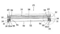
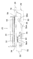
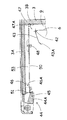
次に、図2及び図11乃至図16を参照してダンパー36について詳述する。図11はダンパー36により背面ダクト6を開放している状態を示す部分拡大縦断側面図、図12はダンパー36により背面ダクト6を閉塞している状態を示す部分拡大縦断側面図、図13は図11の横断平面図、図14は図13の部分拡大図、図15は図12の横断平面図、図16は図15の部分拡大図をそれぞれ示している。   Next, the damper 36 will be described in detail with reference to FIGS. 2 and 11 to 16. 11 is a partially enlarged longitudinal side view showing a state where the rear duct 6 is opened by the damper 36, FIG. 12 is a partially enlarged longitudinal side view showing a state where the rear duct 6 is closed by the damper 36, and FIG. 11, FIG. 14 shows a partially enlarged view of FIG. 13, FIG. 15 shows a transverse plan view of FIG. 12, and FIG. 16 shows a partially enlarged view of FIG.

本実施例では、図2に示すように、背面パネル6には、複数のダンパー36が移動自在に保持されている。具体的には、複数架設される棚のそれぞれの棚方向に対応する位置であって、当該棚に設けられる棚ダクト部材50の連通部51よりの上側にそれぞれ左右に延在する透孔37、37が形成されており、当該透孔37にダンパー36が保持されている。本実施例では、棚25の後方に対応する位置(実際には、棚25に設けられる棚ダクト部材50の連通部51)よりも少許上側及び、棚26の後方に対応する位置(実際には、棚26に設けられる棚ダクト部材50の連通部51)よりも少許上側に透孔37が設けられ、それぞれにダンパー36が保持されている。   In the present embodiment, as shown in FIG. 2, a plurality of dampers 36 are movably held on the back panel 6. Specifically, through-holes 37 that extend to the left and right at positions corresponding to the respective shelf directions of a plurality of shelves and above the communication part 51 of the shelf duct member 50 provided on the shelf, 37 is formed, and the damper 36 is held in the through hole 37. In the present embodiment, the position corresponding to the rear side of the shelf 25 (actually the communication portion 51 of the shelf duct member 50 provided on the shelf 25) and the position corresponding to the rear side of the shelf 26 (actually). The through holes 37 are provided on the slightly upper side of the communicating portion 51) of the shelf duct member 50 provided on the shelf 26, and the damper 36 is held in each.

なお、本実施例では、ダンパー36が取り付けられる位置を棚後方に対応する位置よりも少許上方としているが、棚が架設された状態で、当該棚に対応して形成される連通孔54より上方、且つ、当該棚前方から容易に視認可能な位置であることが望ましい。また、ここでは、ダンパー36が対応して設けられる棚は棚25と棚26としているが、これに限定されるものではなく、他の棚についても同様に透孔37を形成しダンパー36を保持しても良い。   In the present embodiment, the position where the damper 36 is attached is slightly above the position corresponding to the rear of the shelf, but in the state where the shelf is installed, the position above the communication hole 54 formed corresponding to the shelf. And it is desirable that the position is easily visible from the front of the shelf. In addition, here, the shelves provided with the dampers 36 are the shelves 25 and 26, but the shelves are not limited thereto, and the other shelves are similarly formed with the through holes 37 to hold the dampers 36. You may do it.

透孔37は、ダンパー36を内部において移動可能とするため、背面パネル6の左右に延在して形成されており、当該ダンパー36の厚さ寸法よりも少許広い間隔を有し、ダンパー36の移動を容易としている。   The through-holes 37 are formed to extend to the left and right of the back panel 6 so that the damper 36 can move inside. The through holes 37 have a gap that is slightly larger than the thickness dimension of the damper 36, and Easy to move.

ダンパー36は、陳列室11の背部、即ち、背面パネル6に位置して背面ダクト6の左右寸法に対応する寸法(実際には、少許小さい寸法)に形成される閉塞板部38と、当該閉塞板部38を背面パネル6に着脱自在に保持する固定具39により構成される。   The damper 36 includes a closing plate portion 38 formed on the back portion of the display chamber 11, that is, on the back panel 6 and having a size (actually a small size) corresponding to the left and right dimensions of the back duct 6. The plate part 38 is configured by a fixture 39 that detachably holds the back panel 6.

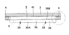
閉塞板部38は、断面略L字状を呈しており、当該上面38Aは、例えば、当該取付位置における背面ダクト6の前端から後端に延在する寸法に形成されており、当該後端38Bは、両側端部38C、38Cが透孔37の幅よりも外方に延在した幅広形状とされている(図14、図16)。また、後端38Bは、所定角度にて上側に折曲して形成されており、後述する如くダンパー36が手前側に位置した状態で、背面パネル6後面に沿う形状とされている(図11)。   The closing plate portion 38 has a substantially L-shaped cross section, and the upper surface 38A is formed, for example, in a dimension extending from the front end to the rear end of the rear duct 6 at the attachment position, and the rear end 38B. The both side end portions 38C, 38C have a wide shape extending outwardly from the width of the through hole 37 (FIGS. 14 and 16). Further, the rear end 38B is formed by bending upward at a predetermined angle, and has a shape along the rear surface of the rear panel 6 with the damper 36 positioned on the near side as will be described later (FIG. 11). ).

一方、閉塞板部38の上面38A前端が所定角度、具体的には、背面パネル6の傾斜角度に沿って下側に折曲することで構成される前面38Dの例えば、両側部には、前記固定具39が取り付けられている。この固定具39は、操作部39Aの一端に固定される突出部材39Bと、当該突出部材39Bを囲繞する軟質樹脂製の保持部材39Cとから構成されている。当該保持部材39Cは、突出部材39Bを先端から操作部39A側に渡って切り割り形状とされている。他方、背面パネル6には、当該固定具39に対応する位置に、固定孔40が形成されている。   On the other hand, the front surface 38A front end of the closing plate portion 38 is bent at a predetermined angle, specifically, along the inclination angle of the back panel 6, for example, on both sides of the front surface 38D. A fixture 39 is attached. The fixture 39 includes a protruding member 39B fixed to one end of the operation portion 39A, and a soft resin holding member 39C surrounding the protruding member 39B. The holding member 39C has a slit shape extending from the tip to the operation portion 39A side of the protruding member 39B. On the other hand, a fixing hole 40 is formed in the back panel 6 at a position corresponding to the fixing tool 39.

係る構成により、ダンパー36により背面ダクト9を閉塞する際には、先ず、閉塞板部38の前面38Dの前面に取り付けられた固定具39の操作部39Aを持って、閉塞板部38の上面38Aを奥側、即ち背面ダクト9に押し込み、固定具39の保持部材39Cをそのまま背面パネル6の固定孔40に押し込むことで、保持部材39Cが切り割りに沿って開き、内方に設けられた突出部材39Bが露出する。これによって、切り割りに沿って開かれた保持部材39Cにより、固定具39が背面パネル6の固定孔40に保持され、容易に抜け出ることを防止することができ、固定具39により安定して閉塞板部38による背面ダクト9の閉塞状態を維持することが可能となる(図12、図15、図16)。   With this configuration, when the rear duct 9 is closed by the damper 36, first, the operation unit 39A of the fixture 39 attached to the front surface of the front surface 38D of the closing plate portion 38 is held, and the upper surface 38A of the closing plate portion 38 is retained. Is pushed into the back side duct 9, that is, the holding member 39C of the fixture 39 is pushed into the fixing hole 40 of the back panel 6 as it is, so that the holding member 39C is opened along the slit, and a protruding member provided inwardly. 39B is exposed. Accordingly, the fixing member 39 is held in the fixing hole 40 of the back panel 6 by the holding member 39 </ b> C opened along the cut and can be prevented from easily coming out. It becomes possible to maintain the closed state of the back surface duct 9 by the part 38 (FIG. 12, FIG. 15, FIG. 16).

このとき、閉塞板部38の上面後端38Bは、背面ダクト9の背面、具体的には、断熱壁3の前面近傍に位置すると共に、当該対応する部分には、シール部材41が設けられている。そのため、ダンパー36の閉塞板部38が奥側に押し込まれた状態では、閉塞板部38の後端がシール部材41と密着して固定されることで、背面ダクト9がダンパー36により閉塞され、背面ダクト9内を上昇してくる冷気のダンパー36より上側への供給が停止される。   At this time, the upper rear end 38B of the closing plate portion 38 is located on the rear surface of the rear duct 9, specifically, in the vicinity of the front surface of the heat insulating wall 3, and a seal member 41 is provided in the corresponding portion. Yes. Therefore, in a state where the closing plate portion 38 of the damper 36 is pushed into the back side, the rear duct 9 is closed by the damper 36 by fixing the rear end of the closing plate portion 38 in close contact with the sealing member 41, The supply of the cold air rising in the rear duct 9 to the upper side from the damper 36 is stopped.

他方、ダンパー36により背面ダクト9を開放する際には、先ず、前記固定具39の操作部39Aを前方に引くことによって、突出部材39Cを背面ダクト9側から退避させ、保持部材39Cが閉じた状態とし、当該固定具39と固定孔40との固定を解除する。その後、閉塞板部38を手前側に引き出し、背面ダクト9を開放する。   On the other hand, when the rear duct 9 is opened by the damper 36, first, the projecting member 39C is retracted from the rear duct 9 side by pulling the operation portion 39A of the fixture 39 forward, and the holding member 39C is closed. The fixing tool 39 and the fixing hole 40 are released from the fixed state. Thereafter, the closing plate portion 38 is pulled out to the front side, and the rear duct 9 is opened.

この状態で、閉塞板部38の後端38Dは、背面パネル6の透孔37の縁部に係合して背面パネル6に保持される。ここで、閉塞板部38の後端38Dは、両端部38C、38Cが背面パネル6の透孔37の幅よりも外方に延在した幅広形状とされているため、当該後端38Dが透孔37から脱落しない構成とすることができる(図14)。従って、ダンパー36が背面パネル6に固定されずに手前側に引き出された状態であっても、閉塞板部38の後端38Dが透孔37縁部に支持されることで、安定した保持状態を維持することが可能となる。従って、当該ダンパー36を組み込む際には、製品の組み立ての時点で、背面パネル6の背方から透孔37に固定具39を取り付ける以前の閉塞板部38を挿入し、背面パネル6の前方から閉塞板部38に固定具39を取り付ける。   In this state, the rear end 38 </ b> D of the closing plate 38 is engaged with the edge of the through hole 37 of the back panel 6 and is held by the back panel 6. Here, since the rear end 38D of the closing plate portion 38 has a wide shape in which both end portions 38C and 38C extend outward from the width of the through hole 37 of the back panel 6, the rear end 38D is transparent. It can be set as the structure which does not drop from the hole 37 (FIG. 14). Accordingly, even when the damper 36 is pulled out to the near side without being fixed to the back panel 6, the rear end 38 </ b> D of the closing plate 38 is supported by the edge of the through hole 37, so that the stable holding state is achieved. Can be maintained. Therefore, when assembling the damper 36, at the time of assembly of the product, the closing plate portion 38 before attaching the fixture 39 to the through hole 37 is inserted from the back of the back panel 6, and from the front of the back panel 6. A fixing tool 39 is attached to the closing plate portion 38.

なお、本実施例では、後端38Dは、透孔37の左右幅寸法より外方に延在した構成とされているが、これに限定されるものではなく、当該後端38Dが容易に透孔37から脱落しない構成であれば、例えば、後端38の上下寸法を透孔37の上下寸法よりも幅広としても良い。   In the present embodiment, the rear end 38D is configured to extend outward from the lateral width dimension of the through-hole 37. However, the present invention is not limited to this, and the rear end 38D can be easily penetrated. For example, the vertical dimension of the rear end 38 may be wider than the vertical dimension of the through hole 37 as long as it does not fall out of the hole 37.

また、ダンパー36が手前側に引き出された状態では、閉塞板部38の上側に折曲された後端38Dが背面パネル6の後面に沿う形状とされていることから、後端38Dが背面パネル6の後面に沿った状態で透孔37縁部に係支させることができ、ダンパー36全体をより背面パネル6に沿わせた状態で保持することができる(図11)。これにより、ダンパー36が背面パネル6から大きく前方に突出することによって、陳列室11内の商品陳列の邪魔となる不都合を抑制することが可能となる。   Further, in the state where the damper 36 is pulled out to the front side, the rear end 38D bent to the upper side of the closing plate portion 38 has a shape along the rear surface of the rear panel 6, so that the rear end 38D is the rear panel. 6 can be engaged with the edge of the through-hole 37 in a state along the rear surface, and the entire damper 36 can be held in a state along the rear panel 6 (FIG. 11). As a result, the damper 36 protrudes greatly forward from the back panel 6, thereby making it possible to suppress inconveniences that hinder the display of products in the display chamber 11.

また、当該ダンパー36は、上述したように棚の後方に対応する位置、実際には、棚に設けられる棚ダクト部材50の連通部51よりも少許上側に保持されていることから、当該ダンパー36を直接視認しながら、背面ダクト9を開放する操作や閉塞する操作を行うことが可能となる。   Further, as described above, the damper 36 is held at a position corresponding to the rear of the shelf, in fact, slightly above the communication portion 51 of the shelf duct member 50 provided on the shelf. It is possible to perform an operation of opening or closing the rear duct 9 while directly visualizing.

従って、従来のように手探りにてダンパーの操作を行う場合に比して、容易に、且つ、確実にダンパー操作を行うことが可能となり、利便性の向上を図ることが可能となる。特に、ダンパー36は、背面パネル6に形成された透孔37に保持されるものであることから、このような簡素な構造にて、背面ダクト9を開放した状態を維持することが可能となる。また、ダンパーが棚に設けられる場合に比して、当該棚自体の構造を簡素化することが可能となり、生産性の向上や、棚自体の重量を軽量化することができる。   Therefore, the damper operation can be easily and surely performed as compared with the conventional case where the damper is operated by groping, and the convenience can be improved. In particular, since the damper 36 is held in the through hole 37 formed in the back panel 6, it is possible to maintain a state in which the back duct 9 is opened with such a simple structure. . Further, the structure of the shelf itself can be simplified as compared with the case where the damper is provided on the shelf, and the productivity can be improved and the weight of the shelf itself can be reduced.

以上の構成で、最上段を構成する棚25より上側の陳列室11を加温領域として加温使用し、棚26より下側の陳列室11を冷却領域として冷蔵使用する場合は、図2に示すように、棚ダクト部材50を棚25の下側に取り付ける。これにより、棚ダクト部材50の後端の連通部51を背面パネル6に形成される連通孔54を介して背面ダクト9に連通させる。そして、当該棚25に設けられる棚ダクト部材50の連通部51よりも上側に位置するダンパー36を奥側に押し込んで、当該高さにて背面ダクト9を閉塞する。なお、これ以外の棚26等の上側に位置するダンパー36は手前側に引き出された状態で保持し、当該高さにおける背面ダクト9を開放する。   In the above configuration, when the display room 11 above the shelf 25 that constitutes the uppermost stage is used as a heating area and the display room 11 below the shelf 26 is used as a cooling area, it is shown in FIG. As shown, the shelf duct member 50 is attached to the underside of the shelf 25. As a result, the communication portion 51 at the rear end of the shelf duct member 50 is communicated with the rear duct 9 through the communication hole 54 formed in the rear panel 6. And the damper 36 located above the communication part 51 of the shelf duct member 50 provided in the said shelf 25 is pushed in back, and the back surface duct 9 is obstruct | occluded by the said height. In addition, the dampers 36 located on the upper side of the other shelves 26 and the like are held in a state of being pulled out to the near side, and the rear duct 9 at the height is opened.

この状態で、送風機7が運転されると、冷却器15と熱交換した冷気の一部は、背面ダクト9内を上昇し、背面パネル6に形成された連通孔54を介して棚25に取り付けられる棚ダクト部材50の連通部51より棚ダクト53内に流入し、中間冷気吐出口52から陳列室11内下部に向けて吐出される。また、残りの冷気は、背面パネル6に形成された他の連通孔54より陳列室11内に吐出される。   When the blower 7 is operated in this state, a part of the cold air exchanged with the cooler 15 rises in the back duct 9 and is attached to the shelf 25 through the communication hole 54 formed in the back panel 6. Then, the air flows into the shelf duct 53 from the communication portion 51 of the shelf duct member 50 and is discharged from the intermediate cold air discharge port 52 toward the lower part in the display chamber 11. Further, the remaining cold air is discharged into the display chamber 11 from another communication hole 54 formed in the back panel 6.

棚ダクト部材50の前端下面に形成された中間冷気吐出口52から吐出された冷気は、棚25より下側の陳列室11の前面開口に冷気エアーカーテンを形成しながら当該陳列室11内を冷却する。そして、冷気吸込口17から下部ダクト14に吸引され、再び送風機7に吸い込まれる循環を繰り返す。   The cool air discharged from the intermediate cool air discharge port 52 formed on the lower surface of the front end of the shelf duct member 50 cools the inside of the display chamber 11 while forming a cool air curtain in the front opening of the display chamber 11 below the shelf 25. To do. And the circulation which is attracted | sucked by the lower duct 14 from the cold air inlet 17 and is suck | inhaled by the air blower 7 again is repeated.

従って、最上段の棚25より下側の陳列室11内は、当該棚25の下側に取り付けられる棚ダクト部材50を介して前面開口に冷気供給されることにより、冷却領域とされ冷蔵使用することができる。他方、最上段の棚25の電気ヒータHは、各ダンパー36に別途設けられるダンパーセンサの検出出力や、操作パネルの入力により通電される。これにより、最上段の棚25より上側の陳列室11内は、冷気供給の停止及び電気ヒータHの通電により加温領域とされ、温蔵使用することができるようになる。   Therefore, the inside of the display chamber 11 below the uppermost shelf 25 is cooled and supplied to the front opening through the shelf duct member 50 attached to the lower side of the shelf 25 to be used as a cooling region. be able to. On the other hand, the electric heater H of the uppermost shelf 25 is energized by the detection output of a damper sensor provided separately to each damper 36 or the input of the operation panel. As a result, the inside of the display chamber 11 above the uppermost shelf 25 is set as a heating region by stopping the supply of cold air and energizing the electric heater H, and can be used in a refrigerated state.

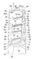
次に、図17を参照して、上から二段目の棚26より上側の陳列室11内を加温領域として使用し、棚27より下側の陳列室11内を冷却領域として使用する場合について説明する。この場合、他の位置に取り付けられていた棚ダクト部材50を取り外し、当該棚26の下側に上述したように棚ダクト部材50を取り付ける。これにより、棚ダクト部材50の後端の連通部51を背面パネル6に形成される連通孔54を介して背面ダクト9に連通させる。そして、当該棚26に設けられる棚ダクト部材50の連通部51よりも上側に位置するダンパー36、本実施例では上から2つめのダンパー36を奥側に押し込んで、当該高さにて背面ダクト9を閉塞する。なお、これ以外の棚25等の上側に位置するダンパー36は手前側に引き出された状態で保持し、当該高さにおける背面ダクト9を開放する。   Next, referring to FIG. 17, when the inside of the display chamber 11 above the shelf 26 second from the top is used as a heating region, and the inside of the display chamber 11 below the shelf 27 is used as a cooling region. Will be described. In this case, the shelf duct member 50 attached to another position is removed, and the shelf duct member 50 is attached to the lower side of the shelf 26 as described above. As a result, the communication portion 51 at the rear end of the shelf duct member 50 is communicated with the rear duct 9 through the communication hole 54 formed in the rear panel 6. And the damper 36 located above the communication part 51 of the shelf duct member 50 provided in the shelf 26, in this embodiment, the second damper 36 from the top is pushed into the back side, and the rear duct is at the height. 9 is closed. In addition, the damper 36 located on the upper side of the other shelf 25 and the like is held in a state of being pulled out to the near side, and the rear duct 9 at the height is opened.

この状態で、送風機7が運転されると、冷却器15と熱交換した冷気の一部は、背面ダクト9内を上昇し、背面パネル6に形成された連通孔54を介して上から二段目の棚26に取り付けられる棚ダクト部材50の連通部51より棚ダクト53内に流入し、中間冷気吐出口52から陳列室11内下部に向けて吐出される。また、残りの冷気は、背面パネル6に形成された他の連通孔54より陳列室11内に吐出される。   In this state, when the blower 7 is operated, a part of the cool air exchanged with the cooler 15 rises in the back duct 9 and passes through the communication holes 54 formed in the back panel 6 from the top. It flows into the shelf duct 53 from the communicating portion 51 of the shelf duct member 50 attached to the eye shelf 26, and is discharged from the intermediate cold air discharge port 52 toward the lower part in the display chamber 11. Further, the remaining cold air is discharged into the display chamber 11 from another communication hole 54 formed in the back panel 6.

棚ダクト部材50の前端下面に形成された中間冷気吐出口52から吐出された冷気は、棚26より下側の陳列室11の前面開口に冷気エアーカーテンを形成しながら当該陳列室11内を冷却する。そして、冷気吸込口17から下部ダクト14に吸引され、再び送風機7に吸い込まれる循環を繰り返す。   The cool air discharged from the intermediate cool air discharge port 52 formed on the lower surface of the front end of the shelf duct member 50 cools the inside of the display chamber 11 while forming a cool air curtain in the front opening of the display chamber 11 below the shelf 26. To do. And the circulation which is attracted | sucked by the lower duct 14 from the cold air inlet 17 and is suck | inhaled by the air blower 7 again is repeated.

従って、上から二段目の棚26より下側の陳列室11内は、当該棚26の下側に取り付けられる棚ダクト部材50を介して前面開口に冷気供給されることにより、冷却領域とされ冷蔵使用することができる。他方、最上段の棚25及び棚26の電気ヒータHは、各ダンパー36に別途設けられるダンパーセンサの検出出力や、操作パネルの入力により通電される。これにより、上から二段目の棚26より上側の陳列室11内は、冷気供給の停止及び電気ヒータHの通電により加温領域とされ、温蔵使用することができるようになる。   Accordingly, the inside of the display chamber 11 below the second shelf 26 from the top is set as a cooling region by being supplied with cold air to the front opening through the shelf duct member 50 attached to the lower side of the shelf 26. Can be used refrigerated. On the other hand, the electric heaters H of the uppermost shelf 25 and the shelf 26 are energized by the detection output of a damper sensor separately provided in each damper 36 or the input of the operation panel. As a result, the inside of the display chamber 11 above the second shelf 26 from the top is set as a warming region by stopping the supply of cold air and energizing the electric heater H, and can be used in a warm state.

他方、陳列室11内全体を冷却領域として冷蔵使用する場合には、他の位置に取り付けられていた棚ダクト部材50を取り外し、図18に示すように、陳列室11の天井部3Aの下側に上述の如く棚ダクト部材50を取り付ける。これにより、棚ダクト部材50の中間冷気吐出口52が背面ダクト上端9に対応し、連通部51が冷気吐出部材44の冷気導入口44Bに対応して、棚ダクト部材50内の棚ダクト53を介して背面ダクト9上端と冷気吐出口44Aとが連通される。そして、背面パネル6に保持される全てのダンパー36を手前側に引き出された状態で保持する。   On the other hand, when the entire display chamber 11 is refrigerated and used as a cooling region, the shelf duct member 50 attached to another position is removed, and the lower side of the ceiling portion 3A of the display chamber 11 is removed as shown in FIG. As described above, the shelf duct member 50 is attached. Accordingly, the intermediate cold air discharge port 52 of the shelf duct member 50 corresponds to the rear duct upper end 9, and the communication portion 51 corresponds to the cold air inlet 44 </ b> B of the cold air discharge member 44, so that the shelf duct 53 in the shelf duct member 50 is connected. The upper end of the back duct 9 and the cold air outlet 44A are communicated with each other. And all the dampers 36 hold | maintained at the back panel 6 are hold | maintained in the state pulled out by this side.

この状態で、冷気循環用の送風機7が運転されると、冷却器15と熱交換した冷気は、背面ダクト9内を上昇し、下向きに開口された中間冷気吐出口52より円滑に棚ダクト53内に流入する。特に、この場合、棚25等に取り付けられた際に、前端に下向きに開口された中間冷気吐出口52を反転させ、当該中間冷気吐出口52を背面ダクト9上端に設けることによって、背面ダクト9内を上昇してくる冷気を下向きに開口された中間冷気吐出口52により円滑に棚ダクト53内に流入させることが可能となる。   When the blower 7 for circulating cold air is operated in this state, the cold air that has exchanged heat with the cooler 15 rises in the back duct 9 and smoothly passes through the shelf duct 53 from the intermediate cold air outlet 52 that opens downward. Flows in. In particular, in this case, when attached to the shelf 25 or the like, the intermediate cold air discharge port 52 opened downward at the front end is reversed, and the intermediate cold air discharge port 52 is provided at the upper end of the rear duct 9, whereby the rear duct 9 The cold air rising inside can be smoothly introduced into the shelf duct 53 by the intermediate cold air discharge port 52 opened downward.

また、棚ダクト部材50の連通部51は、冷気吐出部材44の冷気導入口44Bに対応して取り付けられているため、当該冷気吐出部材44の冷気導入口44Bから流入した冷気は、開口上縁の下向きに開口して形成される冷気吐出口44Aより陳列室の前面に冷気のエアーカーテンを形成しながら陳列室11内を冷却する。そして、冷気吸込口17から下部ダクト14に吸引され、再び送風機7に吸い込まれる循環を繰り返す。これによって、陳列室11内の全域が冷蔵温度に冷却された冷却領域とされて、全棚上の商品が冷却されることになる。   Further, since the communication portion 51 of the shelf duct member 50 is attached to correspond to the cold air inlet 44B of the cold air discharge member 44, the cold air flowing from the cold air inlet 44B of the cold air discharge member 44 is The inside of the display chamber 11 is cooled while a cool air curtain is formed on the front surface of the display chamber from the cool air discharge port 44A formed to open downward. And the circulation which is attracted | sucked by the lower duct 14 from the cold air inlet 17 and is suck | inhaled by the air blower 7 again is repeated. As a result, the entire area in the display chamber 11 is set as a cooling region cooled to the refrigeration temperature, and the products on all the shelves are cooled.

なお、陳列室11内全体を加熱領域として温蔵使用とする場合には、冷却装置及び送風機7を停止し、全段の棚25、26、27、28の電気ヒータHに通電し、各棚上の商品を加温する。   When the entire display chamber 11 is used as a heating area for storage, the cooling device and the blower 7 are stopped, the electric heaters H of the shelves 25, 26, 27, and 28 of all stages are energized, Warm the product above.

このように、本発明によれば、使用形態に応じて棚ダクト部材50を棚25、26や陳列室11の天井部3Aに設けることにより、当該使用形態に適した陳列室11への冷気供給を実現することが可能となる。   As described above, according to the present invention, the shelf duct member 50 is provided on the shelves 25 and 26 or the ceiling portion 3A of the display chamber 11 according to the usage pattern, thereby supplying cold air to the display chamber 11 suitable for the usage pattern. Can be realized.

特に、棚ダクト部材50を棚25や26に取り付ける場合と陳列室11の天井部3Aに取り付ける場合とで共通の棚ダクト部材50を選択的に付け替えることで対応することが可能となり、ショーケース1全体の部品点数を大幅に削減することが可能となる。これにより、生産コストの削減や組立作業性の向上を図ることが可能となる。また、当該棚ダクト部材50は、常に陳列室11内に取り付けられているので、別途保管する必要がなく、紛失するおそれがない。   In particular, it is possible to cope with the case where the shelf duct member 50 is attached to the shelves 25 and 26 and the case where the shelf duct member 50 is attached to the ceiling portion 3A of the display chamber 11 by selectively replacing the common shelf duct member 50. The total number of parts can be greatly reduced. This makes it possible to reduce production costs and improve assembly workability. Further, since the shelf duct member 50 is always mounted in the display chamber 11, it is not necessary to store it separately and there is no possibility of losing it.

また、棚ダクト部材50が取り付けられる棚以外の棚や、陳列室11の天井部3Aに棚ダクト部材50が取り付けられた状態での各棚は、棚ダクト部材が設けられないことから棚自体を薄く構成することができ、限られた陳列室11内を有効に利用することが可能となる。   In addition, a shelf other than the shelf to which the shelf duct member 50 is attached, and each shelf in a state where the shelf duct member 50 is attached to the ceiling portion 3A of the display chamber 11 are not provided with the shelf duct member. It can be made thin, and the inside of the limited display room 11 can be used effectively.

特に、当該棚下に位置する棚の商品陳列容積を拡大することができるため、商品陳列効果の向上を図ることができると共に、ショーケース1全体として棚構造が簡素化されるため美観の向上を図ることができる。   In particular, since the product display volume of the shelf located under the shelf can be increased, the product display effect can be improved, and the shelf structure of the showcase 1 as a whole is simplified, thereby improving the aesthetic appearance. be able to.

なお、本実施例におけるショーケース1では、冷却領域として使用される以外の棚は、電気ヒータHを通電することにより、温蔵使用としているが、これに限定されるものではなく、加熱や冷却を行わない非冷(常温)使用としても良い。これにより、棚ダクト部材50を取り付ける位置と、背面ダクト9を閉塞するダンパー36を任意に操作することによって、当該ダンパー36より上側の陳列室への冷気供給を停止することができ、陳列室11内に異なる温度帯を形成することが可能となる。   In the showcase 1 in the present embodiment, the shelves other than those used as the cooling region are kept warm by energizing the electric heater H. However, the present invention is not limited to this, and heating and cooling are not limited thereto. It is good also as non-cold (room temperature) use without performing. Accordingly, by arbitrarily operating the position at which the shelf duct member 50 is attached and the damper 36 that closes the rear duct 9, the supply of cold air to the display room above the damper 36 can be stopped, and the display room 11. Different temperature zones can be formed inside.

本発明を適用したショーケースの斜視図である。It is a perspective view of a showcase to which the present invention is applied. 図1のショーケースの縦断側面図(最上段に棚ダクト部材を取り付けた状態)である。FIG. 2 is a longitudinal side view of the showcase of FIG. 1 (a state in which a shelf duct member is attached to the uppermost stage). 棚の縦断正面図である。It is a vertical front view of a shelf. 図3の部分拡大図である。FIG. 4 is a partially enlarged view of FIG. 3. 棚ダクト部材の取付状態を示す陳列室側からみた側面図である。It is the side view seen from the display room side which shows the attachment state of a shelf duct member. 棚及び棚ダクト部材の一部切欠縦断側面図である。It is a partially cut vertical side view of a shelf and a shelf duct member. ダクト部材の底面図である。It is a bottom view of a duct member. ショーケース上部拡大縦断側面図である。It is a showcase upper part expansion vertical side view. 同じくショーケース上部拡大縦断側面図である。It is a showcase upper part expansion vertical side view similarly. 冷気吐出口を後方からみた部分拡大図である。It is the elements on larger scale which looked at the cold air discharge outlet from back. ダンパーにより背面ダクトを開放している状態を示す部分拡大縦断側面図である。It is a partial expanded vertical side view which shows the state which has open | released the back surface duct with the damper. ダンパーにより背面ダクトを閉塞している状態を示す部分拡大縦断側面図である。It is a partial expanded vertical side view which shows the state which has block | closed the back surface duct with the damper. 図11の横断平面図である。It is a cross-sectional plan view of FIG. 図13の部分拡大図である。It is the elements on larger scale of FIG. 図12の横断平面図である。FIG. 13 is a cross-sectional plan view of FIG. 12. 図15の部分拡大図である。It is the elements on larger scale of FIG. 図1のショーケースの縦断側面図(上から二段目の棚に棚ダクト部材を取り付けた状態)である。FIG. 2 is a longitudinal side view of the showcase of FIG. 1 (a state in which a shelf duct member is attached to the second shelf from the top). 図1のショーケースの縦断側面図(陳列室の天井部下側に棚ダクト部材を取り付けた状態)である。It is a vertical side view of the showcase of FIG. 1 (a state where a shelf duct member is attached to the lower side of the ceiling portion of the display room).

符号の説明Explanation of symbols

H 加温用ヒータ(電気ヒータ)
1 ショーケース
3 断熱壁
3A 天井部
6 背面パネル
7 送風機
11 陳列室
17 冷気吸込口
25、26、27、28 棚
30 ブラケット
33 棚板
36 ダンパー
37 透孔
38 閉塞板部
38A 上面
38B 後端
38C 側端部
38D 前面
39 固定具
39A 操作部
39B 突出部材
39C 保持部材
40 固定孔
41 シール材
42 ヒンジ部材
43 開閉パネル部
43A 当接面
44 冷気吐出部材
44A 冷気吐出口
44B 冷気導入口
46 吊下部材
47 保持部材
47A 上面
48 化粧ビス
50 棚ダクト部材
51 連通部
52 中間冷気吐出口
53 棚ダクト
54 連通孔
55 係支棒
56 取付部材
56A 係合孔
58 保持板
59 吊下部材
59A 係止部
60 保持片
H Heating heater (electric heater)
DESCRIPTION OF SYMBOLS 1 Showcase 3 Heat insulation wall 3A Ceiling part 6 Rear panel 7 Blower 11 Display room 17 Cold-air inlet 25, 26, 27, 28 Shelf 30 Bracket 33 Shelf board 36 Damper 37 Through-hole 38 Closure board part 38A Upper surface 38B Rear end 38C side End part 38D Front surface 39 Fixing tool 39A Operation part 39B Projection member 39C Holding member 40 Fixing hole 41 Sealing material 42 Hinge member 43 Opening and closing panel part 43A Abutting surface 44 Cold air discharge member 44A Cold air discharge port 44B Cold air introduction port 46 Suspension member 47 Holding member 47A Upper surface 48 Cosmetic screw 50 Shelf duct member 51 Communication part 52 Intermediate cold air outlet 53 Shelf duct 54 Communication hole 55 Support rod 56 Mounting member 56A Engagement hole 58 Holding plate 59 Suspension member 59A Locking part 60 Holding piece

Claims (3)

断熱壁内に前面が開口する陳列室を構成し、該陳列室内に商品陳列用の棚を架設して成るショーケースにおいて、
前記陳列室の背面に位置し、前記断熱壁との間に冷気が上昇する背面ダクトを構成するための背面パネルと、
前記棚に設けられ、後端の連通部にて前記背面ダクトに連通すると共に、前端に冷気吐出口が形成された棚ダクトと、
前記連通部の上側において、前記背面ダクトを閉塞するためのダンパーとを備え、
該ダンパーは、前記背面パネルに形成された透孔に移動自在に保持されて前記背面ダクトを閉塞するための閉塞板部と、前記背面パネルに着脱自在に固定するための固定具とを有し、
前記背面パネルに固定されずに手前側に引き出された状態で、前記閉塞板部は前記背面パネルの透孔縁部に係合して当該ダンパーは前記背面パネルに保持され、前記背面ダクトは開放されると共に、奥側に押し込まれ、前記固定具により前記背面パネルに固定された状態で、前記閉塞板部は前記背面ダクトを閉塞することを特徴とするショーケース。
In a showcase comprising a display room having a front opening in a heat insulating wall, and a shelf for displaying products in the display room.
A back panel for configuring a back duct that is located on the back of the display room and in which cool air rises between the heat insulating wall;
A shelf duct provided on the shelf and communicating with the rear duct at a rear end communication portion, and a cold air discharge port formed at the front end,
On the upper side of the communication portion, comprising a damper for closing the back duct,
The damper includes a closing plate portion that is movably held in a through hole formed in the back panel and closes the back duct, and a fixing tool that is detachably fixed to the back panel. ,
In a state where it is pulled out to the near side without being fixed to the back panel, the closing plate portion engages with a through-hole edge of the back panel, the damper is held by the back panel, and the back duct is opened. In addition, the showcase is characterized in that the closing plate portion closes the back duct while being pushed into the back side and fixed to the back panel by the fixture.
前記閉塞板部の後端は、前記透孔の幅よりも幅広とされていることを特徴とする請求項1に記載のショーケース。   The showcase according to claim 1, wherein a rear end of the blocking plate portion is wider than a width of the through hole. 前記閉塞板部の後端は上側に折曲されており、前記ダンパーが手前側に位置した状態で、前記背面パネル後面に沿うことを特徴とする請求項2に記載のショーケース。   3. The showcase according to claim 2, wherein a rear end of the blocking plate portion is bent upward, and is along the rear surface of the back panel in a state where the damper is positioned on the near side.
JP2007242408A 2007-09-19 2007-09-19 Showcase Expired - Fee Related JP5118924B2 (en)

Priority Applications (1)

Application Number Priority Date Filing Date Title
JP2007242408A JP5118924B2 (en) 2007-09-19 2007-09-19 Showcase

Applications Claiming Priority (1)

Application Number Priority Date Filing Date Title
JP2007242408A JP5118924B2 (en) 2007-09-19 2007-09-19 Showcase

Publications (2)

Publication Number Publication Date
JP2009072283A JP2009072283A (en) 2009-04-09
JP5118924B2 true JP5118924B2 (en) 2013-01-16

Family

ID=40607921

Family Applications (1)

Application Number Title Priority Date Filing Date
JP2007242408A Expired - Fee Related JP5118924B2 (en) 2007-09-19 2007-09-19 Showcase

Country Status (1)

Country Link
JP (1) JP5118924B2 (en)

Families Citing this family (5)

* Cited by examiner, † Cited by third party
Publication number Priority date Publication date Assignee Title
JP5493672B2 (en) * 2009-10-09 2014-05-14 富士電機株式会社 Showcase
KR20160099304A (en) * 2015-02-12 2016-08-22 코오롱인더스트리 주식회사 Hollow Fiber Membrane Bundle and Method for Manufacturing thereof
JP6769117B2 (en) * 2016-05-31 2020-10-14 富士電機株式会社 Showcase intermediate duct
JP2019202056A (en) * 2018-05-25 2019-11-28 東芝キヤリア株式会社 Open showcase
JP7196576B2 (en) * 2018-12-04 2022-12-27 富士電機株式会社 Product shelf and showcase

Family Cites Families (3)

* Cited by examiner, † Cited by third party
Publication number Priority date Publication date Assignee Title
JPS4824056U (en) * 1971-07-06 1973-03-20
JPS5211468A (en) * 1975-07-18 1977-01-28 Hitachi Ltd Wind quantity regulating device for refrigerator
JP2005156034A (en) * 2003-11-26 2005-06-16 Sanyo Electric Co Ltd Showcase

Also Published As

Publication number Publication date
JP2009072283A (en) 2009-04-09

Similar Documents

Publication Publication Date Title
JP5556208B2 (en) Showcase
JP5118924B2 (en) Showcase
JP5175512B2 (en) Showcase
JP2006275375A (en) Open showcase
JP4097594B2 (en) Showcase
JP5919514B2 (en) Showcase
JP4596926B2 (en) Showcase
JP4179902B2 (en) Showcase
JP2005156117A (en) Showcase
JP4348157B2 (en) Showcase
JP4637079B2 (en) Showcase
JP3920092B2 (en) Showcase
JP2718469B2 (en) Showcase
JP2010082208A (en) Showcase
JP5493672B2 (en) Showcase
JP5611607B2 (en) Open showcase
JP4895702B2 (en) Showcase
JPH11241880A (en) Open showcase
JP2007130226A (en) Showcase
JPH0894232A (en) Showcase
JP2004069233A (en) Showcase
JP2024008103A (en) Show case
JP4179757B2 (en) Showcase
JP2005131037A (en) Showcase
JP2006296928A (en) Low temperature show case

Legal Events

Date Code Title Description
A621 Written request for application examination

Free format text: JAPANESE INTERMEDIATE CODE: A621

Effective date: 20100830

A977 Report on retrieval

Free format text: JAPANESE INTERMEDIATE CODE: A971007

Effective date: 20120913

TRDD Decision of grant or rejection written
A01 Written decision to grant a patent or to grant a registration (utility model)

Free format text: JAPANESE INTERMEDIATE CODE: A01

Effective date: 20120925

A01 Written decision to grant a patent or to grant a registration (utility model)

Free format text: JAPANESE INTERMEDIATE CODE: A01

A61 First payment of annual fees (during grant procedure)

Free format text: JAPANESE INTERMEDIATE CODE: A61

Effective date: 20121022

FPAY Renewal fee payment (event date is renewal date of database)

Free format text: PAYMENT UNTIL: 20151026

Year of fee payment: 3

LAPS Cancellation because of no payment of annual fees