JP5118905B2 - Electrode active material, electrode, non-aqueous electrolyte secondary battery, vehicle, battery-mounted device, and method for producing electrode active material - Google Patents
Electrode active material, electrode, non-aqueous electrolyte secondary battery, vehicle, battery-mounted device, and method for producing electrode active material Download PDFInfo
- Publication number
- JP5118905B2 JP5118905B2 JP2007179065A JP2007179065A JP5118905B2 JP 5118905 B2 JP5118905 B2 JP 5118905B2 JP 2007179065 A JP2007179065 A JP 2007179065A JP 2007179065 A JP2007179065 A JP 2007179065A JP 5118905 B2 JP5118905 B2 JP 5118905B2
- Authority
- JP
- Japan
- Prior art keywords
- active material
- electrode active
- battery
- secondary battery
- electrode
- Prior art date
- Legal status (The legal status is an assumption and is not a legal conclusion. Google has not performed a legal analysis and makes no representation as to the accuracy of the status listed.)
- Expired - Fee Related
Links
Images


Classifications
-
- Y—GENERAL TAGGING OF NEW TECHNOLOGICAL DEVELOPMENTS; GENERAL TAGGING OF CROSS-SECTIONAL TECHNOLOGIES SPANNING OVER SEVERAL SECTIONS OF THE IPC; TECHNICAL SUBJECTS COVERED BY FORMER USPC CROSS-REFERENCE ART COLLECTIONS [XRACs] AND DIGESTS
- Y02—TECHNOLOGIES OR APPLICATIONS FOR MITIGATION OR ADAPTATION AGAINST CLIMATE CHANGE
- Y02E—REDUCTION OF GREENHOUSE GAS [GHG] EMISSIONS, RELATED TO ENERGY GENERATION, TRANSMISSION OR DISTRIBUTION
- Y02E60/00—Enabling technologies; Technologies with a potential or indirect contribution to GHG emissions mitigation
- Y02E60/10—Energy storage using batteries
-
- Y—GENERAL TAGGING OF NEW TECHNOLOGICAL DEVELOPMENTS; GENERAL TAGGING OF CROSS-SECTIONAL TECHNOLOGIES SPANNING OVER SEVERAL SECTIONS OF THE IPC; TECHNICAL SUBJECTS COVERED BY FORMER USPC CROSS-REFERENCE ART COLLECTIONS [XRACs] AND DIGESTS
- Y02—TECHNOLOGIES OR APPLICATIONS FOR MITIGATION OR ADAPTATION AGAINST CLIMATE CHANGE
- Y02T—CLIMATE CHANGE MITIGATION TECHNOLOGIES RELATED TO TRANSPORTATION
- Y02T10/00—Road transport of goods or passengers
- Y02T10/60—Other road transportation technologies with climate change mitigation effect
- Y02T10/62—Hybrid vehicles
Description
本発明は、電極活物質、この電極活物質を備える電極、この電極を備える非水電解質二次電池、この非水電解質二次電池を搭載した車両、電池搭載機器、および電極活物質の製造方法に関する。 The present invention relates to an electrode active material, an electrode including the electrode active material, a non-aqueous electrolyte secondary battery including the electrode, a vehicle equipped with the non-aqueous electrolyte secondary battery, a battery-mounted device, and a method for manufacturing the electrode active material About.
非水電解質二次電池の高機能化、大容量化、低コスト化等の観点から、電極活物質に様々な材料が検討されている。例えば、LiFePO4で表されるオリビン型リチウム含有鉄燐酸錯体を主体とする正極活物質が提案されている(特許文献1参照)。また、一般式:(Li2O)a・(Fe2O3)b・(V2O5)c・(P2O5)d(但し、0≦a≦0.5,0≦b≦0.5,0≦c≦0.5,0≦d≦0.5)で表されるリチウム含有鉄バナジウム燐酸塩ガラスおよびガラスセラミックスを主体とする電極活物質が知られている(特許文献2参照)。 From the viewpoints of high functionality, large capacity, low cost, etc. of the nonaqueous electrolyte secondary battery, various materials have been studied for the electrode active material. For example, a positive electrode active material mainly composed of an olivine-type lithium-containing iron phosphate complex represented by LiFePO 4 has been proposed (see Patent Document 1). Moreover, the general formula: (Li 2 O) a · (Fe 2 O 3) b · (V 2 O 5) c · (P 2 O 5) d ( where, 0 ≦ a ≦ 0.5,0 ≦ b ≦ An electrode active material mainly composed of lithium-containing iron vanadium phosphate glass and glass ceramics represented by 0.5, 0 ≦ c ≦ 0.5, 0 ≦ d ≦ 0.5 is known (Patent Document 2). reference).
特許文献1で提案されているリチウム含有鉄燐酸錯体は、この導電性が低いため、これを正極活物質として非水電解質二次電池に用いた場合、この電池の放電レート特性、低温特性が十分でないという問題がある。そこで、特許文献2では、リチウム含有鉄バナジウム燐酸塩ガラスおよびガラスセラミックスを主体とする電極活物質を非水電解質二次電池の正極に用いることを提案している。これにより、特許文献1のリチウム含有鉄燐酸錯体よりも、この電池の放電レート特性を高くできる。なお、放電レート特性とは、電池を所定の電流で放電させ続けたときに生じる電池電圧の変化の大きさを指し、放電レート特性が高いとは、大きな放電電流で放電させたときでも電池電圧が相対的に低下しにくく、高い値で推移することを指す。
Since the lithium-containing iron phosphate complex proposed in
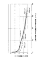
しかしながら、特許文献2にかかる電極活物質を用いた電池でも、放電電流を大きくすると、電池電圧が急激に低下する。つまり、放電レート特性が十分とは言えない。具体例として、図2に、特許文献2にかかる電極活物質(一般式:(Li2O)0.5・(Fe2O3)0.5・(V2O5)0.5・(P2O5)0.5)を非水電解質二次電池の正極に用いて行った際の、放電レート特性を表すグラフを示す(実験詳細条件については後述する)。なお、このグラフの横軸は、正極活物質の単位重量当りの放電容量を、縦軸は電池電圧をそれぞれ示す。 However, even in a battery using the electrode active material according to Patent Document 2, when the discharge current is increased, the battery voltage rapidly decreases. That is, the discharge rate characteristic is not sufficient. As a specific example, FIG. 2 shows an electrode active material (general formula: (Li 2 O) 0.5 · (Fe 2 O 3 ) 0.5 · (V 2 O 5 ) 0.5 · (P 2 O 5 ) 0.5 according to Patent Document 2. ) Is used for the positive electrode of a non-aqueous electrolyte secondary battery, and a graph showing the discharge rate characteristics is shown (detailed experimental conditions will be described later). In this graph, the horizontal axis represents the discharge capacity per unit weight of the positive electrode active material, and the vertical axis represents the battery voltage.
この電池において、正極の単位面積当りの放電電流(以下、単位面積放電電流とも言う)が、0.1あるいは0.2mA/cm2の比較的小さい電流で放電させると、この電池電圧は徐々に低下し、低下の様子もほぼ同じように推移している(例えば、単位重量当りの放電容量が100mAh/gのとき、いずれも電池電圧は2.6Vである)。一方、これらより大きな放電電流、例えば0.5mA/cm2以上の単位面積放電電流に相当する電流で放電させると、この電池電圧は、0.1あるいは0.2mA/cm2で放電させたときの電池電圧よりも、早く低下し、その後は低い値のままで推移する。 In this battery, when the discharge current per unit area of the positive electrode (hereinafter also referred to as unit area discharge current) is discharged with a relatively small current of 0.1 or 0.2 mA / cm 2 , the battery voltage gradually increases. The state of decrease and the state of decrease are almost the same (for example, when the discharge capacity per unit weight is 100 mAh / g, the battery voltage is 2.6 V in all cases). On the other hand, when discharging at a discharge current larger than these, for example, a current corresponding to a unit area discharge current of 0.5 mA / cm 2 or more, the battery voltage is 0.1 or 0.2 mA / cm 2. It drops faster than the battery voltage of, and then remains at a low value.
しかも、この単位面積放電電流が、0.5,1.0,2.0mA/cm2と大きくなるに従い、この電池電圧はより早く低下し、その後、低い値のままで推移することが判る(例えば、電極活物質の単位重量当りの放電容量を100mAh/gとしたときの電池電圧は、それぞれ2.1,1.8,1.5Vである)。つまり、この電極活物質を用いた電池でも、0.5mA/cm2以上の比較的大きな単位面積放電電流で放電させると、短時間で電池の下限電圧に到達してしまうので、放電電流の大きさをあまり大きくすることができない。従って、例えば、この電池をハイブリッド電気自動車に搭載し、急発進や急加速などを行いたい場合でも、この電池では、要求される大きな放電電流を十分に供給できない。あるいは、大きな放電電流を流さない制御を行わざるをえない。 Moreover, it can be seen that as the unit area discharge current increases to 0.5, 1.0, and 2.0 mA / cm 2 , the battery voltage decreases faster and then remains at a low value ( For example, battery voltages when the discharge capacity per unit weight of the electrode active material is 100 mAh / g are 2.1, 1.8, and 1.5 V, respectively). In other words, even with a battery using this electrode active material, if the discharge is performed with a relatively large unit area discharge current of 0.5 mA / cm 2 or more, the lower limit voltage of the battery is reached in a short time. You can't make it too big. Therefore, for example, even when this battery is mounted on a hybrid electric vehicle and sudden start or acceleration is desired, this battery cannot sufficiently supply the required large discharge current. Alternatively, control that does not allow a large discharge current to flow is unavoidable.
本発明は、かかる現状に鑑みてなされたものであって、非水電解質二次電池に使用した場合において、特に大きな放電電流(単位面積放電電流)を流す場合に、リチウム含有鉄バナジウム燐酸塩からなる電極活物質を用いたときよりも、電池の放電レート特性が高くなる電極活物質を提供することを目的とする。またさらに、この電極活物質を用いてなる電極、この電極を用いて高い放電レート特性を有し、大きな放電電流(単位面積放電電流)および電力(電池出力)を得られる非水電解質二次電池、この非水電解質二次電池を搭載した車両並びに電池搭載機器、および電極活物質の製造方法を提供することを目的とする。 The present invention has been made in view of the present situation, and when used in a non-aqueous electrolyte secondary battery, when a particularly large discharge current (unit area discharge current) is passed, the lithium-containing iron vanadium phosphate is used. An object of the present invention is to provide an electrode active material in which the discharge rate characteristics of the battery are higher than when an electrode active material is used. Furthermore, an electrode using this electrode active material, a non-aqueous electrolyte secondary battery having high discharge rate characteristics using this electrode, and capable of obtaining a large discharge current (unit area discharge current) and power (battery output) An object of the present invention is to provide a vehicle on which the nonaqueous electrolyte secondary battery is mounted, a battery-mounted device, and a method for manufacturing an electrode active material.
そして、その解決手段は、非水電解質二次電池の電極に用いる電極活物質であって、一般式:(Li2O)a・(Fe2O3)b・(M2O3)0.5-b・(V2O5)c・(P2O5)d(M:Co,Mn,Niの少なくとも一種)但し、0<a≦0.5,0<b<0.5,0<c≦0.5,0<d≦0.5で表されるリチウム含有鉄バナジウム燐酸塩からなるガラスおよびガラスセラミックスの少なくともいずれかを主体としてなる電極活物質である。
さらに、他の解決手段は、非水電解質二次電池の電極に用いる電極活物質であって、一般式:(Li2O)a・(Fe2O3)b・(Co2O3)0.5-b・(V2O5)c・(P2O5)d但し、0<a≦0.5,0<b<0.5,0<c≦0.5,0<d≦0.5で表されるリチウム含有鉄コバルトバナジウム燐酸塩からなるガラスおよびガラスセラミックスの少なくともいずれかを主体としてなる電極活物質である。
The solution is an electrode active material used for an electrode of a non-aqueous electrolyte secondary battery, which has a general formula: (Li 2 O) a · (Fe 2 O 3 ) b · (M 2 O 3 ) 0.5- b · (V 2 O 5 ) c · (P 2 O 5 ) d (M: at least one of Co, Mn, and Ni) provided that 0 <a ≦ 0.5, 0 <b <0.5, 0 <c It is an electrode active material mainly composed of at least one of glass and glass ceramics made of lithium-containing iron vanadium phosphate represented by ≦ 0.5 and 0 <d ≦ 0.5.
Furthermore, another solution is an electrode active material used for an electrode of a non-aqueous electrolyte secondary battery, which has a general formula: (Li 2 O) a · (Fe 2 O 3 ) b · (Co 2 O 3 ) 0.5 -b. (V 2 O 5 ) c · (P 2 O 5 ) d provided that 0 <a ≦ 0.5, 0 <b <0.5, 0 <c ≦ 0.5, 0 <d ≦ 0. 5 is an electrode active material mainly composed of at least one of glass and glass ceramics made of lithium-containing iron cobalt vanadium phosphate represented by 5.
これらの本発明の電極活物質は、Feおよび金属M(M:Co,Mn,Niの少なくとも一種)あるいはこのうちのCoを共に含有する、リチウム含有鉄バナジウム燐酸塩あるいはリチウム含有鉄コバルトバナジウム燐酸塩からなるガラスおよびガラスセラミックスの少なくともいずれかを主体としている。
この電極活物質を、非水電解質二次電池の電極(正極)に用いた場合、特許文献2の電極活物質、つまり、Feを含有するがCoを含めた金属Mを含有しない電極活物質を用いた場合よりも、高い放電レート特性を有する電池を構成できる。特に、放電電流が大きい(単位面積放電流が0.5mA/cm2以上)の場合に、放電に伴う電池電圧の低下を抑制できる。かくして、本発明の電極活物質は、これを非水電解質二次電池の電極に用いた場合、大きな放電電流を流すことができ、また、大きな電力(電池出力)を得ることができる。
These electrode active materials of the present invention include lithium-containing iron vanadium phosphate or lithium-containing iron cobalt vanadium phosphate containing both Fe and metal M (M: at least one of Co, Mn, and Ni) or Co. The main component is at least one of glass and glass ceramics.
When this electrode active material is used for an electrode (positive electrode) of a nonaqueous electrolyte secondary battery, the electrode active material of Patent Document 2, that is, an electrode active material containing Fe but not containing metal M including Co is used. A battery having a higher discharge rate characteristic than when used can be configured. In particular, when the discharge current is large (unit area discharge current is 0.5 mA / cm 2 or more), it is possible to suppress a decrease in battery voltage due to discharge. Thus, when the electrode active material of the present invention is used for an electrode of a nonaqueous electrolyte secondary battery, a large discharge current can flow and a large power (battery output) can be obtained.
一方、特許文献1で提案されているようなオリビン型リチウム含有鉄燐酸錯体LiFePO4では、この構成元素であるFeをCoにしても、これを電極に用いてなる非水電解質二次電池の放電レート特性は高くできない(文献:Journal of Power Sources 160(2006) 523−528)。しかし、このLiFePO4にバナジウムを添加し、更に、本発明のように、このうちのFeの一部を金属MあるいはこのうちのCoに置換して、Feと共に金属MあるいはこのうちのCoを含有させると、それを用いる電池では、上述のとおり放電レート特性を向上させることができる。従って、リチウム含有鉄バナジウム燐酸において、Feの一部を金属MあるいはこのうちのCoと共に含有させると、それを用いた電池の放電レート特性は高いものとなるという新しい知見が得られた。
On the other hand, in the olivine-type lithium-containing iron phosphate complex LiFePO 4 proposed in
なお、上述の電極活物質の一般式に用いられている符号a,b,c,dは、0<a≦0.5,0<b<0.5,0<c≦0.5,0<d≦0.5の範囲を満たせば良いが、好ましくは、a=c=d=0.5、かつ、0.2≦b≦0.3である。このような組成の電極活物質を非水電解質二次電池に用いることで、確実に高い放電レート特性を有する電池を構成することができる。 The symbols a, b, c, and d used in the general formula of the electrode active material are 0 <a ≦ 0.5, 0 <b <0.5, 0 <c ≦ 0.5, 0. <D ≦ 0.5 may be satisfied, but preferably a = c = d = 0.5 and 0.2 ≦ b ≦ 0.3. By using an electrode active material having such a composition for a non-aqueous electrolyte secondary battery, a battery having high discharge rate characteristics can be reliably configured.
また、この電極活物質において、挿入・離脱するカチオンとしては、リチウムイオン、ナトリウムイオン、カリウムイオン、セシウムイオン等のアルカリ金属イオン、また、カルシウムイオン、バリウムイオン等のアルカリ土類金属、マグネシウムイオン、アルミニウムイオン、銀イオン、亜鉛イオン、テトラブチルアンモニウムイオン、テトラエチルアンモニウムイオン、テトラメチルアンモニウムイオン、トリエチルアンモニウムイオン等のアンモニウムイオン類、イミダゾリウムイオン、エチルメチルイミダゾリウムイオン等のイミダゾリウムイオン類、ピリジニウムイオン、水素イオン、テトラエチルホスホニウムイオン、テトラメチルホスホニウムイオン、テトラフェニルホスホニウムイオン、テトラフェニルスルホニウムイオン、トリエチルホスホニウムイオン等が挙げられる。これらのうち、アルカリ金属イオンを用いるのが好ましく、リチウムイオンを用いるのがより好ましい。 Further, in this electrode active material, as the cations to be inserted / leaved, alkali metal ions such as lithium ion, sodium ion, potassium ion and cesium ion, alkaline earth metals such as calcium ion and barium ion, magnesium ion, Ammonium ions such as aluminum ion, silver ion, zinc ion, tetrabutylammonium ion, tetraethylammonium ion, tetramethylammonium ion and triethylammonium ion, imidazolium ions such as imidazolium ion and ethylmethylimidazolium ion, pyridinium ion , Hydrogen ion, tetraethylphosphonium ion, tetramethylphosphonium ion, tetraphenylphosphonium ion, tetraphenylsulfonium ion Triethyl phosphonium ion, and the like. Of these, alkali metal ions are preferably used, and lithium ions are more preferably used.
また、本発明の電極活物質は、他の電池構成材料、特に他方の電極を構成する電極活物質の選択等によって、正極活物質として用いることも、あるいは、負極活物質として用いることもできる。但し、その電位から、本発明の電極活物質は、正極活物質として用いることが好ましい。本発明の電極活物質を正極活物質として用いる場合、その対極である負極活物質としては、Li、Na、Mg、Ca、Al等の金属、または、これらの合金、あるいは、カチオンを挿入・離脱可能な炭素材料等を用いることができる。 The electrode active material of the present invention can be used as a positive electrode active material or a negative electrode active material depending on selection of other battery constituent materials, particularly the electrode active material constituting the other electrode. However, from the potential, the electrode active material of the present invention is preferably used as a positive electrode active material. When the electrode active material of the present invention is used as a positive electrode active material, as a negative electrode active material that is the counter electrode, metals such as Li, Na, Mg, Ca, Al, alloys thereof, or cations are inserted / extracted. Possible carbon materials can be used.
さらに、上述の電極活物質であって、a=c=d=0.5、かつ、0.2≦b≦0.3を満たしてなる電極活物質とすると良い。 Furthermore, the electrode active material described above may be an electrode active material satisfying a = c = d = 0.5 and 0.2 ≦ b ≦ 0.3.
a=c=d=0.5、かつ、0.2≦b≦0.3を満たす本発明の電極活物質を非水電解質二次電池の電極に用いた場合、特許文献2に記載した電極活物質を用いた場合に比して、高い放電レート特性を有する電池を構成することができる。特に、放電電流が大きい(単位面積放電流が0.5mA/cm2以上)場合では、放電に伴う電池電圧の低下を確実に抑制できる。かくして、本発明の電極活物質は、これを非水電解質二次電池の電極に用いると、大きな放電電流を確実に流すことができる。 When the electrode active material of the present invention satisfying a = c = d = 0.5 and 0.2 ≦ b ≦ 0.3 is used for the electrode of the nonaqueous electrolyte secondary battery, the electrode described in Patent Document 2 Compared with the case where an active material is used, a battery having high discharge rate characteristics can be configured. In particular, when the discharge current is large (unit area discharge current is 0.5 mA / cm 2 or more), it is possible to reliably suppress a decrease in battery voltage due to discharge. Thus, when the electrode active material of the present invention is used for an electrode of a non-aqueous electrolyte secondary battery, a large discharge current can surely flow.
さらに、他の解決手段は、上述の電極活物質を備えてなる電極である。 Furthermore, another solution is an electrode comprising the above-described electrode active material.
本発明の電極では、上述の電極活物質を備えている。よって、この電極を非水電解質二次電池の電極として用いた場合、高い放電レート特性を有する電池としうる。特に、この電池の放電電流が大きい(単位面積放電電流が0.5mA/cm2以上)場合に、放電に伴う電池電圧の低下を抑制できる。 The electrode of the present invention includes the above-described electrode active material. Therefore, when this electrode is used as an electrode of a nonaqueous electrolyte secondary battery, it can be a battery having high discharge rate characteristics. In particular, when the discharge current of this battery is large (the unit area discharge current is 0.5 mA / cm 2 or more), it is possible to suppress a decrease in battery voltage due to discharge.
なお、電極としては、例えば、この電極活物質を圧縮成形して、円板形状、角板形状など各種形状のペレット状の電極が挙げられる。また、金属等の導電性材料からなる集電体(あるいは集電箔)の主面上に、本発明の電極活物質を広範に担持してなる電極板(あるいは電極箔)も挙げられる。 In addition, as an electrode, this electrode active material is compression-molded, and the electrode of the pellet shape of various shapes, such as a disk shape and a square plate shape, is mentioned, for example. Moreover, the electrode plate (or electrode foil) which carries | supports the electrode active material of this invention extensively on the main surface of the electrical power collector (or current collector foil) which consists of electroconductive materials, such as a metal, is also mentioned.
さらに、他の解決手段は、上述の電極を備える非水電解質二次電池である。 Furthermore, another solution is a nonaqueous electrolyte secondary battery including the above-described electrode.
本発明の非水電解質二次電池では、上述の電極を備えている。このため、高い放電レート特性を有する電池としうる。特に、この電池の放電電流が大きい(単位面積放電電流が0.5mA/cm2以上)場合に、放電に伴う電池電圧の低下を抑制できる。従って、大きな放電電流および電力(電池出力)を供給可能な非水電解質二次電池とすることができる。 The nonaqueous electrolyte secondary battery of the present invention includes the above-described electrode. For this reason, it can be set as the battery which has a high discharge rate characteristic. In particular, when the discharge current of this battery is large (the unit area discharge current is 0.5 mA / cm 2 or more), it is possible to suppress a decrease in battery voltage due to discharge. Therefore, it can be set as the nonaqueous electrolyte secondary battery which can supply a big discharge current and electric power (battery output).
さらに、他の解決手段は、上述の非水電解質二次電池を搭載してなる車両である。 Furthermore, another solution is a vehicle on which the above-described non-aqueous electrolyte secondary battery is mounted.
本発明の車両では、上述の非水電解質二次電池を搭載している。この非水電解質二次電池は、0.5mA/cm2以上の単位面積放電電流に相当する大きな放電電流および電力(電池出力)を、車輪を駆動するモータに供給できる。このため、急発進や急加速をスムーズに行いうる走行性能を有する車両とすることができる。 In the vehicle of the present invention, the above-described non-aqueous electrolyte secondary battery is mounted. This non-aqueous electrolyte secondary battery can supply a large discharge current and electric power (battery output) corresponding to a unit area discharge current of 0.5 mA / cm 2 or more to a motor for driving the wheel. For this reason, it can be set as the vehicle which has the driving performance which can perform sudden start and rapid acceleration smoothly.
さらに、上述の車両であって、前記非水電解質二次電池について、前記電極の単位面積当りの放電電流が0.5mA/cm2以上となる大きさの放電電流での放電を許容する放電制御装置を搭載してなる車両とすると良い。 Further, in the above-described vehicle, the non-aqueous electrolyte secondary battery is configured to allow discharge with a discharge current having a magnitude such that a discharge current per unit area of the electrode is 0.5 mA / cm 2 or more. The vehicle is preferably equipped with a device.
本発明の車両では、前述の非水電解質二次電池のほか、0.5mA/cm2以上の単位面積放電電流に相当する放電電流での放電を許容する放電制御装置を搭載している。この車両では、放電制御装置の制御に従って、非水電解質二次電池から、0.5mA/cm2以上の単位面積放電電流に相当する比較的大きな放電電流および電力(電池出力)を、車輪を駆動するモータに供給できる。このため、急発進や急加速をスムーズに行いうる走行性能を有する車両とすることができる。 In the vehicle of the present invention, in addition to the non-aqueous electrolyte secondary battery described above, a discharge control device that allows discharge at a discharge current corresponding to a unit area discharge current of 0.5 mA / cm 2 or more is mounted. In this vehicle, the wheel is driven by a relatively large discharge current and electric power (battery output) corresponding to a unit area discharge current of 0.5 mA / cm 2 or more from the nonaqueous electrolyte secondary battery according to the control of the discharge control device. Can be supplied to the motor. For this reason, it can be set as the vehicle which has the driving performance which can perform sudden start and rapid acceleration smoothly.
なお、電池を搭載した車両としては、その動力源の全部あるいは一部に電池による電気エネルギを使用している車両であれば良く、例えば、電気自動車、ハイブリッド電気自動車、フォークリフト、電気車いす、電動アシスト自転車、電動スクータ、鉄道車両が挙げられる。また、前述の電池を用いることにより、充放電制御装置における制御可能な放電電流の範囲を大電流側に拡げることができる。従って特に、動力源の一部に電池の電気エネルギを使用している車両、例えばハイブリッド電気自動車に適用する場合に、エンジンによる車輪の駆動に対する、駆動用モータによる車輪の駆動の割合を高めて、燃費向上を図った車両とすることができる利点がある。 Note that a vehicle equipped with a battery may be any vehicle that uses electric energy from a battery for all or a part of its power source. For example, an electric vehicle, a hybrid electric vehicle, a forklift, an electric wheelchair, an electric assist Bicycles, electric scooters, and railway vehicles are examples. Further, by using the above-described battery, the controllable discharge current range in the charge / discharge control device can be expanded to the large current side. Therefore, particularly when applied to a vehicle using electric energy of a battery as a part of a power source, for example, a hybrid electric vehicle, the ratio of driving the wheel by the driving motor to the driving of the wheel by the engine is increased. There is an advantage that the vehicle can be improved in fuel efficiency.
さらに、他の解決手段は、前述の非水電解質二次電池を搭載した電池搭載機器である。 Furthermore, another solution is a battery-equipped device on which the nonaqueous electrolyte secondary battery is mounted.
本発明の電池搭載機器では、上述の非水電解質二次電池を搭載している。従って、この電池により、一時的に大きな放電電流および電力(電池出力)を要するような使用方法でも使用可能な電池搭載機器とすることができる。 The battery-equipped device of the present invention is equipped with the above-described non-aqueous electrolyte secondary battery. Therefore, this battery can be a battery-equipped device that can be used even in a usage method that temporarily requires a large discharge current and electric power (battery output).
なお、電池搭載機器としては、搭載した電池をエネルギ源の少なくとも1つとして利用する機器であれば良く、例えば、パーソナルコンピュータ、携帯電話、電池駆動の電動工具など、電池で駆動される各種の家電製品、オフィス機器、産業機器が挙げられる。但し、一時的に大きな放電電流および電力(電池出力)を必要とする電動工具および産業機器に適用するのがより好ましい。 The battery-mounted device may be any device that uses the mounted battery as at least one of the energy sources. For example, various home appliances driven by a battery such as a personal computer, a mobile phone, and a battery-driven electric tool. Products, office equipment and industrial equipment. However, it is more preferable to apply to electric tools and industrial equipment that temporarily require a large discharge current and electric power (battery output).
さらに、他の解決手段は、非水電解質二次電池の電極に用いる電極活物質であって、一般式:(Li2O)a・(Fe2O3)b・(M2O3)0.5-b・(V2O5)c・(P2O5)d(M:Co,Mn,Niの少なくとも一種)但し、0<a≦0.5,0<b<0.5,0<c≦0.5,0<d≦0.5で表されるリチウム含有鉄バナジウム燐酸塩からなるガラスおよびガラスセラミックスの少なくともいずれかを主体としてなる電極活物質の製造方法であって、Li、Fe、M、V、Pの五元素を含む化合物を所定モル比で混合した混合物を加熱して溶融する溶融工程と、その後、これを急冷して凝固させる凝固工程と、その後、これをガラス転移温度以上融点以下の温度に、加熱保持するアニーリング処理工程と、を備える電極活物質の製造方法である。
さらに、他の解決手段は、非水電解質二次電池の電極に用いる電極活物質であって、一般式:(Li2O)a・(Fe2O3)b・(Co2O3)0.5-b・(V2O5)c・(P2O5)d但し、0<a≦0.5,0<b<0.5,0<c≦0.5,0<d≦0.5で表されるリチウム含有鉄コバルトバナジウム燐酸塩からなるガラスおよびガラスセラミックスの少なくともいずれかを主体としてなる電極活物質の製造方法であって、Li、Fe、Co、V、Pの五元素を含む化合物を所定モル比で混合した混合物を加熱して溶融する溶融工程と、その後、これを急冷して凝固させる凝固工程と、その後、これをガラス転移温度以上融点以下の温度に、加熱保持するアニーリング処理工程と、を備える電極活物質の製造方法である。
Furthermore, another solution is an electrode active material used for an electrode of a non-aqueous electrolyte secondary battery, which has a general formula: (Li 2 O) a · (Fe 2 O 3 ) b · (M 2 O 3 ) 0.5 -b · (V 2 O 5 ) c · (P 2 O 5 ) d (M: at least one of Co, Mn, and Ni) where 0 <a ≦ 0.5, 0 <b <0.5, 0 < A method for producing an electrode active material mainly comprising at least one of glass and glass ceramics comprising lithium-containing iron vanadium phosphate represented by c ≦ 0.5, 0 <d ≦ 0.5, wherein Li, Fe , A melting step of heating and melting a mixture in which compounds containing five elements of M, V, and P are mixed at a predetermined molar ratio, a solidifying step of rapidly cooling and solidifying the mixture, and a glass transition temperature thereof. An annealing treatment step of heating and holding at a temperature not lower than the melting point and not higher than the melting point, It is a production method.
Furthermore, another solution is an electrode active material used for an electrode of a non-aqueous electrolyte secondary battery, which has a general formula: (Li 2 O) a · (Fe 2 O 3 ) b · (Co 2 O 3 ) 0.5 -b. (V 2 O 5 ) c · (P 2 O 5 ) d provided that 0 <a ≦ 0.5, 0 <b <0.5, 0 <c ≦ 0.5, 0 <d ≦ 0. A method for producing an electrode active material mainly composed of at least one of glass and glass ceramics made of lithium-containing iron cobalt vanadium phosphate represented by 5, comprising five elements of Li, Fe, Co, V, and P A melting step for heating and melting a mixture in which compounds are mixed at a predetermined molar ratio, a solidification step for rapidly cooling and solidifying the mixture, and an annealing for heating and holding the mixture at a temperature not lower than the glass transition temperature and not higher than the melting point. A process for producing the electrode active material.
これらの本発明の電極活物質の製造方法は、溶融工程と、凝固工程、アニーリング処理工程とを備える。よって、Feおよび、金属MあるいはこのうちのCoのほか、Li、V、Pを含有する、リチウム含有鉄バナジウム燐酸塩あるいはリチウム含有鉄コバルトバナジウム燐酸塩からなるガラスおよびガラスセラミックスの少なくともいずれかを主体とした電極活物質を製造可能である。 These electrode active material manufacturing methods of the present invention include a melting step, a solidification step, and an annealing treatment step. Therefore, the main component is at least one of glass and glass ceramics made of lithium-containing iron vanadium phosphate or lithium-containing iron cobalt vanadium phosphate containing Li, V, and P in addition to Fe and metal M or Co. The electrode active material can be manufactured.
なお、溶融工程において、Li、Fe、金属MあるいはこのうちのCo、V、Pの五元素の供給源となりうる化合物としては、例えば、これらの元素と酸素とからなる酸化物が挙げられる。
また、アニーリング処理工程における加熱温度としては、処理する電極活物質のガラス転移温度と融点の間の温度を選択すると良い。
In the melting step, examples of the compound that can be a supply source of Li, Fe, metal M, or five elements of Co, V, and P thereof include oxides composed of these elements and oxygen.
Moreover, as the heating temperature in the annealing treatment step, a temperature between the glass transition temperature and the melting point of the electrode active material to be treated is preferably selected.
さらに、他の解決手段は、上述の電極活物質の製造方法であって、前記アニーリング処理工程は、結晶化温度以上融点以下の温度に加熱保持する工程である電極活物質の製造方法とすると良い。 Furthermore, another solution is the above-described method for producing an electrode active material, wherein the annealing treatment step is preferably a method for producing an electrode active material which is a step of heating and holding at a temperature not lower than the crystallization temperature and not higher than the melting point. .
本発明の電極活物質の製造方法は、アニーリング処理工程において、結晶化温度以上融点以下の温度に加熱保持する。これにより、より良好な電位伝導性を有する電極活物質を製造することができる。 In the method for producing an electrode active material of the present invention, in the annealing treatment step, the electrode active material is heated and held at a temperature not lower than the crystallization temperature and not higher than the melting point. Thereby, an electrode active material having better potential conductivity can be produced.
アニーリング処理工程における加熱温度としては、例えば、前述のLiFe0.5Co0.5VPO7((Li2O)0.5・(Fe2O3)0.25・(Co2O3)0.25・(V2O5)0.5・(P2O5)0.5)の結晶化温度は、ガラス転移温度よりも高い465℃であり、融点は600℃であるので、加熱温度としては、その範囲内とするのが良く、例えば500℃とすると良い。 As the heating temperature in the annealing treatment step, for example, the above-described LiFe 0.5 Co 0.5 VPO 7 ((Li 2 O) 0.5. (Fe 2 O 3 ) 0.25. (Co 2 O 3 ) 0.25. (V 2 O 5 ) 0.5 The crystallization temperature of (P 2 O 5 ) 0.5 ) is 465 ° C., which is higher than the glass transition temperature, and the melting point is 600 ° C. Therefore, the heating temperature is preferably within that range, for example 500 It should be ℃.
(実施形態1)
まず、本発明の実施形態1について、図面を参照しつつ説明する。
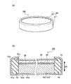
図1は、本実施形態1にかかるリチウムイオン二次電池100(以下、単に電池100とも言う)であり、図1(a)は、この電池100の斜視図、図1(b)は拡大縦断面図である。
この電池100は、正極活物質1を主体に圧縮成形してなる正極10のほか、電池ケース50、負極20、セパレータ30、および図示しない電解液からなる、非水電解質二次電池である。
(Embodiment 1)
First,
FIG. 1 shows a lithium ion secondary battery 100 (hereinafter also simply referred to as a battery 100) according to
This
このうち、電池ケース50は、ステンレス鋼板からなり、底部51aが円形で、高さ方向DHに厚さを有する概略コイン形状を有している。具体的には、その高さ方向DHの厚さ(高さ)が2mm、円形の直径が32mm(2032型)のコイン型電池ケースである。この電池ケース50は、容器体51と蓋体52とを有する。このうち、容器体51は、円板状の底部51a、および、この周縁からこれに直交する方向に立ち上がり、先端側が内側に曲げられると共に縮径する形態の円筒壁部51bからなる。また、蓋体52は円板形状を有し、円筒壁部51bの先端で構成される開口部51cを封口してなる。これら容器体51と蓋体52との間には、絶縁体のガスケット53が介在しており、それぞれ正極端子および負極端子を兼ねている。
この電池ケース50の内部には、一組の正極10と負極20が、セパレータ30を介して、高さ方向DHに積層してある(図2(b)参照)。なお、正極10は容器体51の底部51a側に、負極20は蓋体52側にそれぞれ配置されて電気的に接続する。さらに、上述のガスケット53は、負極20が、正極端子となる容器体51の円筒壁部51bに触れることを防止すべく、円筒壁部51bの内表面51bxの全てと、底板51aの内表面51axの一部を被覆している。
Among these, the
Inside the
次いで、本実施形態1にかかる正極10について説明する。この正極10は、正極活物質1、アセチレンブラック(AB)からなる導電材5、および、ポリテトラフルオロエチレン(PTFE)からなる結着剤6の混合物を圧縮成形したものである。具体的には、正極活物質1、導電材5および結着剤6を、それぞれ0.250g、0.089gおよび0.018gずつ混合して(質量比では70:25:5)、直径10mm、厚さ0.5mmの円板形状のペレットに圧縮成形してなる。
一方、負極20としては、直径15mm、厚さ0.15mmの円形リチウム箔を用いた。また、セパレータ30としては、直径20mm、厚さ0.02mmの多孔質ポリエチレンシートを用いた。さらに、電解液としては、エチレンカーボネートとジエチルカーボネートとの体積比1:1の混合溶媒に、1モル/lの濃度でLiPF6を溶解させたものを使用した。この電解液は、上述のセパレータ30内部に吸収担持されている。
Next, the positive electrode 10 according to the first embodiment will be described. This positive electrode 10 is obtained by compression molding a mixture of a positive electrode
On the other hand, a circular lithium foil having a diameter of 15 mm and a thickness of 0.15 mm was used as the
次いで、本実施形態1にかかる正極活物質1について説明する。
この正極活物質1は、リチウム含有鉄コバルトバナジウム燐酸塩のうち、(Li2O)0.5・(Fe2O3)0.25・(Co2O3)0.25・(V2O5)0.5・(P2O5)0.5で表されるガラス体である。この正極活物質の結晶化温度および融点は、465℃および600℃である。なお、これらの温度については、DTA(Differential Thermal Analysis:示差熱分析)により求めた。
Next, the positive electrode
This positive electrode
さらに、本実施形態1にかかる正極活物質1をリチウムイオン二次電池の正極に用いた場合の、この電池の放電レート特性を調査した。
Furthermore, the discharge rate characteristic of this battery when the positive electrode
上述の正極活物質1の比較例として、コバルトを含有しない、特許文献2に記載の正極活物質2((Li2O)0.5・(Fe2O3)0.5・(V2O5)0.5・(P2O5)0.5)を用意した。
これら正極活物質1,2を用いて、正極活物質以外は上述のリチウムイオン二次電池100と同仕様の電池C1,C2をそれぞれ作製した。そして、これらの電池C1,C2について、放電レート特性を評価した。具体的には、25℃の温度環境下、電池C1,C2に対して、正極単位面積当りの充電電流が0.1mA/cm2に相当する充電電流で、電池電圧が5Vとなるまでの定電流充電と、単位面積放電電流が0.1、0.2、0.5、1.0、および、2.0mA/cm2のいずれか1つによる定電流放電(放電を終了する電池電圧は1V)とを繰り返した。しかも、単位面積放電電流が小さい順に放電を行った。つまり、充電後にまず、0.1mA/cm2の単位面積放電電流での定電流放電を行い、その後、再び充電をしたら、次いで、0.2mA/cm2の単位面積放電電流での定電流放電を行うといった具合に、2.0mA/cm2の定電流放電まで充放電を行った。この試験結果について、図2および図3に示す。
As a comparative example of the positive electrode
Using these positive electrode
図2は、コバルトを含有しない、従来の正極活物質2を用いた電池C2における、放電レート特性を示すグラフである。なお、このグラフの横軸は、正極活物質2の単位重量当りの放電容量を、縦軸は電池C2の電池電圧をそれぞれ示す。
この電池C2では、前述したとおり、0.5mA/cm2以上の単位面積放電電流で放電させると、0.1あるいは0.2mA/cm2の単位面積放電電流で放電させた場合に比べ、放電容量は少ないにも拘わらず、電池電圧がすぐに低下し、低いままで推移している。しかも、この単位面積放電電流の値が大きくなると、放電による電池電圧はより早い段階で大きく低下し、その後は低いままで推移することが判る。
FIG. 2 is a graph showing the discharge rate characteristics in the battery C2 using the conventional positive electrode active material 2 that does not contain cobalt. In addition, the horizontal axis of this graph shows the discharge capacity per unit weight of the positive electrode active material 2, and the vertical axis shows the battery voltage of the battery C2.
In the battery C2, as described above, when discharged with a unit area discharge current of 0.5 mA / cm 2 or more, discharge is performed as compared with the case of discharging with a unit area discharge current of 0.1 or 0.2 mA / cm 2. Despite the small capacity, the battery voltage quickly dropped and remained low. Moreover, it can be seen that when the value of the unit area discharge current is increased, the battery voltage due to the discharge is greatly reduced at an earlier stage and thereafter remains low.
一方、図3は、正極活物質1を用いた電池C1における放電レート特性を示すグラフである。このグラフにおける横軸は、正極活物質1の単位重量当りの放電容量を、縦軸は電池C1の電池電圧をそれぞれ示す。
この電池C1では、いずれの単位面積放電電流で放電させた場合でも、放電の初期に電池電圧が3V付近まで降下した後は、電池電圧が、ほぼ直線的に緩やかに減少する。この電池C1でも、上述の電池C2と同様に、単位面積放電電流の値が大きくなるほど、電池電圧は大きく低下する。しかし、0.5mA/cm2以上の比較的大きな単位面積放電電流で放電させた場合について、電池C2の場合と比較すれば明らかなように、放電による電池電圧の低下が少ないことが判る。上述の電池C2、および電池C1について、正極活物質の単位重量当りの放電容量が100mAh/gとなったときの、各単位面積放電電流における電池電圧を表1に示す。
On the other hand, FIG. 3 is a graph showing discharge rate characteristics in the battery C1 using the positive electrode
In the battery C1, regardless of which unit area discharge current is used for discharge, the battery voltage gradually decreases almost linearly after the battery voltage drops to around 3 V at the beginning of discharge. In this battery C1, as in the case of the above-described battery C2, the battery voltage greatly decreases as the unit area discharge current value increases. However, as is clear from the case of discharging with a relatively large unit area discharge current of 0.5 mA / cm 2 or more as compared with the case of the battery C2, it can be seen that the decrease in the battery voltage due to the discharge is small. Table 1 shows the battery voltage at each unit area discharge current when the discharge capacity per unit weight of the positive electrode active material was 100 mAh / g for the above-described battery C2 and battery C1.

この表1から判るように、その単位重量当りの放電容量が100mAh/gとなるまで、電池C1,C2を放電させるにあたり、単位面積放電電流が0.1、および0.2mA/cm2では、これらの電池電圧はいずれも2.6V程度であり、互いに差異はないことが判る。一方、0.5mA/cm2以上の比較的大きい単位面積放電電流に相当する放電をさせると、電池C1は、その電池電圧を電池C2の電池電圧よりも0.4〜0.5V程度高く保てることが判る。つまり、電池C1では、放電電流を大きくしても、電池C2ほどには大きな電池電圧の低下が生じないことが判る。 As can be seen from Table 1, when discharging the batteries C1 and C2 until the discharge capacity per unit weight becomes 100 mAh / g, the unit area discharge current is 0.1 and 0.2 mA / cm 2 , These battery voltages are all about 2.6 V, and it can be seen that there is no difference between them. On the other hand, when a discharge corresponding to a relatively large unit area discharge current of 0.5 mA / cm 2 or more is performed, the battery C1 can keep the battery voltage about 0.4 to 0.5 V higher than the battery voltage of the battery C2. I understand that. That is, in the battery C1, it can be seen that even if the discharge current is increased, the battery voltage does not decrease as much as the battery C2.
以上の結果から判るように、本実施形態1の電池100と同様の電池C1は、0.5mA/cm2以上の比較的大きな単位面積放電電流に相当する放電電流で放電させた場合、電池C2よりその電池電圧を高く保つことができる。つまり、このリチウムイオン二次電池100は、従来よりも大きな放電電流および電力(電池電圧)を継続して供給することができる。かくして、本実施形態1にかかる正極活物質1は、これをリチウムイオン二次電池100の正極10に用いることで放電レート特性の高い電池を構成することができる。
As can be seen from the above results, when the battery C1 similar to the
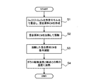
次いで、本実施形態1にかかる正極活物質1の製造方法について、図4を参照しつつ説明する。
まず、ステップS1において、Li2O粉末Cl、Fe2O3粉末Cf、Co2O3粉末Cc、V2O5粉末Cv、P2O5粉末Cpを、モル比2:1:1:2:2の割合で混合した。次いで、溶融工程となるステップS2に進み、この混合原料CMを電気炉中に1000℃で60分間加熱、溶融した。
次に、凝固工程となるステップS3では、溶融した混合原料CMを、急冷処理して凝固させた。具体的には、予め冷蔵庫で冷却していた銅板上に、溶融した混合原料CMを流し出して、急冷してガラス化した。
さらに、アニーリング処理工程となるステップS4では、予めDTAで測定しておいた、この組成を有する正極活物質1のガラス転移温度および融点に基づき、これらの中間の温度、さらには結晶化温度と融点の中間の温度、中でも結晶化温度に近い500℃にて連続200分間、加熱を施した。
Next, a method for producing the positive electrode
First, in step S1, Li 2 O powder Cl, Fe 2 O 3 powder Cf, Co 2 O 3 powder Cc, V 2 O 5 powder Cv, and P 2 O 5 powder Cp are mixed at a molar ratio of 2: 1: 1: 2. : Mixed at a ratio of 2. Subsequently, it progressed to step S2 used as a melting process, and this mixed raw material CM was heated and melted at 1000 ° C. for 60 minutes in an electric furnace.
Next, in step S3 which is a solidification process, the molten mixed raw material CM was solidified by rapid cooling. Specifically, the molten mixed raw material CM was poured out on a copper plate that had been cooled in advance in a refrigerator, and rapidly cooled to be vitrified.
Further, in step S4, which is an annealing treatment step, based on the glass transition temperature and melting point of the positive electrode
かくして、上述の溶融工程と、凝固工程、アニーリング処理工程とを備える本実施形態1の製造方法により、FeおよびCoのほか、Li、V、Pを含有するリチウム含有鉄コバルトバナジウム燐酸塩からなるガラス体の正極活物質1を製造することができた。
本実施形態1のアニーリング処理工程においては、ガラス転移温度より高い結晶化温度(465℃)以上融点(600℃)以下の温度で、結晶化温度に近い500℃に加熱保持する。これにより、より良好な電位伝導性を有する正極活物質1を製造することができる。
Thus, the glass comprising lithium-containing iron cobalt vanadium phosphate containing Li, V, and P in addition to Fe and Co by the manufacturing method of the first embodiment including the above-described melting step, solidification step, and annealing step. The positive electrode
In the annealing process of the first embodiment, the temperature is maintained at 500 ° C., which is close to the crystallization temperature, at a temperature higher than the glass transition temperature (465 ° C.) and lower than the melting point (600 ° C.). Thereby, the positive electrode
(実施形態2)
次いで、リチウムイオン二次電池100を搭載した車両200について説明する。この車両200は、図5に示すように、リチウムイオン二次電池100を搭載し、エンジン240、フロントモータ220、およびリアモータ230の併用によって車輪280を駆動するハイブリッド電気自動車である。この車両200は、車体270、エンジン240、これに取り付けられたフロントモータ220、リアモータ230、ケーブル250、インバータ260、バッテリパック210、および、エンジン240、フロントモータ220、リアモータ230によって直接または間接に駆動される車輪280を備えている。バッテリパック210は、車両200の車体270に取り付けられている。そして、バッテリパック210の内部には、詳細を図示しないが、電気的に直列に連結されている複数のリチウムイオン二次電池100と、この複数のリチウムイオン二次電池100の充放電を司る充放電制御装置211が配置されている。この充放電制御装置211は、例えば、車両200側のハイブリッドシステム(図示しない)と通信しており、このハイブリッドシステムの指示に従い、リチウムイオン二次電池100の正極活物質を用いた正極10について、0.5mA/cm2以上の単位面積放電電流に相当する放電電流での放電をも許容する制御特性を有している。
(Embodiment 2)
Next, the
従って、本実施形態2の車両200では、充放電制御装置211により、搭載したリチウムイオン二次電池100から、比較的大きな0.5mA/cm2以上の単位面積放電電流に相当する放電電流および電力(電池出力)を、フロントモータ220、リアモータ230に供給し、車輪280を駆動することができる。従って、この電池100の電気エネルギ、またはエンジン240との併用により、急発進や急加速をスムーズに行いうる良好な走行性能を有した車両200とすることができる。しかも、この電池100を用いることで、充放電制御装置211における、制御可能な放電電流の範囲を大電流側に拡げることができるので、車両200において、エンジン240による車輪280の駆動に対する、フロントモータ220、リアモータ230による車輪280の駆動の割合を高めて、燃費向上を図った車両200とすることができる。
Therefore, in the
(実施形態3)
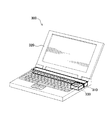
次いで、実施形態1にかかる正極活物質1を正極10に用いたリチウムイオン二次電池100を搭載したノートPC300について説明する。ノートPC300は、電池パック310、本体320を有する電池搭載機器である。電池パック310は、ノートPC300の本体320に収容されており、電池パック310内には、詳細を図示しないが、複数のリチウムイオン二次電池100が電気的に直列に連結されて配置されている。また、この電池パック310に隣接して、この電池パック310の充放電を司る充放電制御装置330が配置されている。この充放電制御装置330は、リチウムイオン二次電池100の正極活物質1を用いた正極10について、0.5mA/cm2以上の単位面積放電電流に相当する放電電流での放電を許容する制御特性を有している。
かくして、本実施形態3にかかるノートPC300では、この電池100により、外部機器やハードディスクの起動など、一時に大きな放電電流および電力(電池出力)を要する場合でも、適切にこれらを駆動可能なノートPC300とすることができる。
(Embodiment 3)
Next, a
Thus, in the
以上において、本発明を実施形態1〜3に即して説明したが、本発明は上記実施形態等に限定されるものではなく、その要旨を逸脱しない範囲で、適宜変更して適用できることは言うまでもない。
例えば、実施形態1では、正極活物質として、リチウム含有鉄バナジウム燐酸塩のうち、金属MがCoであるリチウム含有鉄コバルトバナジウム燐酸塩を用いたが、金属MがMnあるいはNiである、リチウム含有鉄マンガンバナジウム燐酸塩あるいはリチウム含有鉄ニッケルバナジウム燐酸塩を用いても良い。また、実施形態1では、正極として、電極活物質を圧縮成形したペレット状のものとしたが、金属等の導電性材料からなる集電体(集電箔)に、電極活物質を担持させて、電極体、あるいは、電極板としても良い。また、実施形態1では、電池の発電要素として、一対の正極と負極をセパレータを介して重ねた発電要素を用いたが、例えば、複数の正極および負極をセパレータを介して交互に積層した積層型、あるいは、帯状の正極と負極とをセパレータを介して共に捲回してなる捲回型の発電要素を用いても良い。さらに、実施形態1では、非水電解質二次電池の形状をコイン型電池としたが、この形状に限定されるものではなく、用いる発電要素の形状等を考慮して、例えば、直方体形状、円筒形状等としても良い。
In the above, the present invention has been described with reference to the first to third embodiments. However, the present invention is not limited to the above-described embodiments and the like, and it is needless to say that the present invention can be appropriately modified and applied without departing from the gist thereof. Yes.
For example, in
1 正極活物質(電極活物質)
10 正極(電極)
100 リチウムイオン二次電池
200 車両
211 充放電制御装置(放電制御装置)
300 ノートPC(電池搭載機器)
330 充放電制御装置(放電制御装置)
Cc Co2O3粉末(化合物)
Cf Fe2O3粉末(化合物)
Cl Li2O粉末(化合物)
CM 混合原料(混合物)
Cp P2O5粉末(化合物)
Cv V2O5粉末(化合物)
1 Positive electrode active material (electrode active material)
10 Positive electrode (electrode)
100 Lithium ion
300 Notebook PC (Battery-equipped device)
330 Charge / Discharge Control Device (Discharge Control Device)
Cc Co 2 O 3 powder (compound)
Cf Fe 2 O 3 powder (compound)
Cl Li 2 O powder (compound)
CM mixed raw material (mixture)
Cp P 2 O 5 powder (compound)
Cv V 2 O 5 powder (compound)
Claims (11)
一般式:(Li2O)a・(Fe2O3)b・(M2O3)0.5-b・(V2O5)c・(P2O5)d (M:Co,Mn,Niの少なくとも一種)
但し、0<a≦0.5,0<b<0.5,0<c≦0.5,0<d≦0.5
で表されるリチウム含有鉄バナジウム燐酸塩からなるガラスおよびガラスセラミックスの少なくともいずれかを主体としてなる
電極活物質。 An electrode active material used for an electrode of a nonaqueous electrolyte secondary battery,
General formula: (Li 2 O) a · (Fe 2 O 3) b · (M 2 O 3) 0.5-b · (V 2 O 5) c · (P 2 O 5) d (M: Co, Mn, At least one of Ni)
However, 0 <a ≦ 0.5, 0 <b <0.5, 0 <c ≦ 0.5, 0 <d ≦ 0.5
An electrode active material mainly composed of at least one of glass and glass ceramic made of lithium-containing iron vanadium phosphate represented by the formula:
一般式:(Li2O)a・(Fe2O3)b・(Co2O3)0.5-b・(V2O5)c・(P2O5)d
但し、0<a≦0.5,0<b<0.5,0<c≦0.5,0<d≦0.5
で表されるリチウム含有鉄コバルトバナジウム燐酸塩からなるガラスおよびガラスセラミックスの少なくともいずれかを主体としてなる
電極活物質。 An electrode active material used for an electrode of a nonaqueous electrolyte secondary battery,
General formula: (Li 2 O) a · (Fe 2 O 3) b · (Co 2 O 3) 0.5-b · (V 2 O 5) c · (P 2 O 5) d
However, 0 <a ≦ 0.5, 0 <b <0.5, 0 <c ≦ 0.5, 0 <d ≦ 0.5
An electrode active material mainly composed of at least one of glass and glass ceramics comprising lithium-containing iron cobalt vanadium phosphate represented by the formula:
a=c=d=0.5、かつ、0.2≦b≦0.3を満たしてなる
電極活物質。 The electrode active material according to claim 1 or 2,
An electrode active material satisfying a = c = d = 0.5 and 0.2 ≦ b ≦ 0.3.
前記非水電解質二次電池について、前記電極の単位面積当りの放電電流が0.5mA/cm2以上となる大きさの放電電流での放電を許容する放電制御装置を搭載してなる
車両。 The vehicle according to claim 6,
The non-aqueous electrolyte secondary battery is equipped with a discharge control device that allows discharge with a discharge current having a magnitude of 0.5 mA / cm 2 or more per unit area of the electrode.
一般式:(Li2O)a・(Fe2O3)b・(M2O3)0.5-b・(V2O5)c・(P2O5)d (M:Co,Mn,Niの少なくとも一種)
但し、0<a≦0.5,0<b<0.5,0<c≦0.5,0<d≦0.5
で表されるリチウム含有鉄バナジウム燐酸塩からなるガラスおよびガラスセラミックスの少なくともいずれかを主体としてなる
電極活物質の製造方法であって、
Li、Fe、M、V、Pの五元素を含む化合物を所定モル比で混合した混合物を加熱して溶融する溶融工程と、
その後、これを急冷して凝固させる凝固工程と、
その後、これをガラス転移温度以上融点以下の温度に、加熱保持するアニーリング処理工程と、を備える
電極活物質の製造方法。 An electrode active material used for an electrode of a nonaqueous electrolyte secondary battery,
General formula: (Li 2 O) a · (Fe 2 O 3) b · (M 2 O 3) 0.5-b · (V 2 O 5) c · (P 2 O 5) d (M: Co, Mn, At least one of Ni)
However, 0 <a ≦ 0.5, 0 <b <0.5, 0 <c ≦ 0.5, 0 <d ≦ 0.5
A method for producing an electrode active material mainly comprising at least one of glass and glass ceramics comprising lithium-containing iron vanadium phosphate represented by:
A melting step of heating and melting a mixture in which compounds containing five elements of Li, Fe, M, V, and P are mixed in a predetermined molar ratio;
Then, a solidification step of rapidly cooling and solidifying this,
Thereafter, an annealing treatment step of heating and maintaining the glass transition temperature to a temperature not lower than the melting point and not higher than the melting point, a method for producing an electrode active material.
一般式:(Li2O)a・(Fe2O3)b・(Co2O3)0.5-b・(V2O5)c・(P2O5)d但し、0<a≦0.5,0<b<0.5,0<c≦0.5,0<d≦0.5
で表されるリチウム含有鉄コバルトバナジウム燐酸塩からなるガラスおよびガラスセラミックスの少なくともいずれかを主体としてなる
電極活物質の製造方法であって、
Li、Fe、Co、V、Pの五元素を含む化合物を所定モル比で混合した混合物を加熱して溶融する溶融工程と、
その後、これを急冷して凝固させる凝固工程と、
その後、これをガラス転移温度以上融点以下の温度に、加熱保持するアニーリング処理工程と、を備える
電極活物質の製造方法。 An electrode active material used for an electrode of a nonaqueous electrolyte secondary battery,
General formula: (Li 2 O) a · (Fe 2 O 3 ) b · (Co 2 O 3 ) 0.5-b · (V 2 O 5 ) c · (P 2 O 5 ) d provided that 0 <a ≦ 0 .5,0 <b <0.5, 0 <c ≦ 0.5, 0 <d ≦ 0.5
A method for producing an electrode active material mainly comprising at least one of glass and glass ceramics comprising lithium-containing iron cobalt vanadium phosphate represented by:
A melting step of heating and melting a mixture in which compounds containing five elements of Li, Fe, Co, V, and P are mixed at a predetermined molar ratio;
Then, a solidification step of rapidly cooling and solidifying this,
Thereafter, an annealing treatment step of heating and maintaining the glass transition temperature to a temperature not lower than the melting point and not higher than the melting point, a method for producing an electrode active material.
前記アニーリング処理工程は、結晶化温度以上融点以下の温度に加熱保持する工程である
電極活物質の製造方法。 It is a manufacturing method of the electrode active material according to claim 9 or 10,
The said annealing process process is a manufacturing method of the electrode active material which is a process heated and hold | maintained to the temperature more than crystallization temperature and below melting | fusing point.
Priority Applications (1)
| Application Number | Priority Date | Filing Date | Title |
|---|---|---|---|
| JP2007179065A JP5118905B2 (en) | 2007-07-06 | 2007-07-06 | Electrode active material, electrode, non-aqueous electrolyte secondary battery, vehicle, battery-mounted device, and method for producing electrode active material |
Applications Claiming Priority (1)
| Application Number | Priority Date | Filing Date | Title |
|---|---|---|---|
| JP2007179065A JP5118905B2 (en) | 2007-07-06 | 2007-07-06 | Electrode active material, electrode, non-aqueous electrolyte secondary battery, vehicle, battery-mounted device, and method for producing electrode active material |
Publications (2)
| Publication Number | Publication Date |
|---|---|
| JP2009016277A JP2009016277A (en) | 2009-01-22 |
| JP5118905B2 true JP5118905B2 (en) | 2013-01-16 |
Family
ID=40356917
Family Applications (1)
| Application Number | Title | Priority Date | Filing Date |
|---|---|---|---|
| JP2007179065A Expired - Fee Related JP5118905B2 (en) | 2007-07-06 | 2007-07-06 | Electrode active material, electrode, non-aqueous electrolyte secondary battery, vehicle, battery-mounted device, and method for producing electrode active material |
Country Status (1)
| Country | Link |
|---|---|
| JP (1) | JP5118905B2 (en) |
Families Citing this family (6)
| Publication number | Priority date | Publication date | Assignee | Title |
|---|---|---|---|---|
| JP2011014373A (en) | 2009-07-02 | 2011-01-20 | Hitachi Powdered Metals Co Ltd | Conductive material and positive electrode material for lithium ion secondary battery using the same |
| JP2011029151A (en) * | 2009-07-02 | 2011-02-10 | Fuji Heavy Ind Ltd | Electrode material and lithium ion secondary battery |
| JP5381588B2 (en) * | 2009-10-02 | 2014-01-08 | トヨタ自動車株式会社 | Lithium ion secondary battery, vehicle and battery-equipped equipment |
| CN102859761B (en) | 2010-03-31 | 2015-06-10 | 株式会社日立制作所 | Positive Electrode Active Material |
| JP2015069935A (en) * | 2013-09-30 | 2015-04-13 | 株式会社 東北テクノアーチ | Vanadium solid salt battery |
| WO2023095889A1 (en) * | 2021-11-26 | 2023-06-01 | 公立大学法人大阪 | Oxide-based positive electrode active material and use of same |
Family Cites Families (4)
| Publication number | Priority date | Publication date | Assignee | Title |
|---|---|---|---|---|
| JP2003157850A (en) * | 2001-11-22 | 2003-05-30 | Kyushu Univ | Positive electrode material for secondary battery and secondary battery |
| JP2004063422A (en) * | 2002-07-31 | 2004-02-26 | Sony Corp | Positive electrode active material and nonaqueous electrolytic battery |
| JP5099737B2 (en) * | 2005-06-30 | 2012-12-19 | 公益財団法人北九州産業学術推進機構 | Electrode active material, method for producing the same, and non-aqueous electrolyte secondary battery |
| JP5034042B2 (en) * | 2006-08-15 | 2012-09-26 | 国立大学法人長岡技術科学大学 | Lithium secondary battery positive electrode material and manufacturing method thereof |
-
2007
- 2007-07-06 JP JP2007179065A patent/JP5118905B2/en not_active Expired - Fee Related
Also Published As
| Publication number | Publication date |
|---|---|
| JP2009016277A (en) | 2009-01-22 |
Similar Documents
| Publication | Publication Date | Title |
|---|---|---|
| JP4709710B2 (en) | Non-aqueous electrolyte battery, battery pack and automobile | |
| JP4799245B2 (en) | Non-aqueous electrolyte battery, battery pack and automobile | |
| JP4421570B2 (en) | Non-aqueous electrolyte battery, battery pack and automobile | |
| JP4580949B2 (en) | Non-aqueous electrolyte battery, battery pack and rechargeable vacuum cleaner | |
| JP4284348B2 (en) | Non-aqueous electrolyte battery, battery pack and automobile | |
| JP6355163B2 (en) | Lithium ion battery | |
| JP6214985B2 (en) | Battery pack, battery pack and automobile | |
| JP2008186803A (en) | Nonaqueous electrolyte battery, battery pack, and automobile | |
| KR20070006592A (en) | Nonaqueous electrolyte battery, battery pack and vehicle | |
| JP5118905B2 (en) | Electrode active material, electrode, non-aqueous electrolyte secondary battery, vehicle, battery-mounted device, and method for producing electrode active material | |
| JP2010225486A (en) | Nonaqueous electrolyte battery | |
| JP2008243729A (en) | Nonaqueous electrolyte battery, battery pack, and automobile | |
| JP2006155941A (en) | Method of manufacture for electrode active material | |
| JP2011103195A (en) | Electrode material, production method of same, and lithium ion secondary battery | |
| JP2014022328A (en) | Method for manufacturing nonaqueous electrolyte secondary battery | |
| US11302916B2 (en) | Methods to stabilize lithium titanate oxide (LTO) by electrolyte pretreatment | |
| JP5618156B2 (en) | Manufacturing method of sealed lithium secondary battery | |
| JP6120065B2 (en) | Nonaqueous electrolyte secondary battery and manufacturing method thereof | |
| JP2014143062A (en) | Nonaqueous electrolyte secondary battery and method for manufacturing the same | |
| JP5975291B2 (en) | Method for producing non-aqueous electrolyte secondary battery | |
| JP2010073498A (en) | Controlling method of charging/discharging of secondary battery, secondary battery system, and hybrid automobile | |
| CN111435729A (en) | Lithium ion secondary battery | |
| JP2013143353A (en) | Lithium ion secondary battery | |
| WO2021111257A1 (en) | Secondary battery, mobile information terminal, and vehicle | |
| US20220384773A1 (en) | Electrochemical Exchange For The Fabrication Of A Layered Anode Material |
Legal Events
| Date | Code | Title | Description |
|---|---|---|---|
| A621 | Written request for application examination |
Free format text: JAPANESE INTERMEDIATE CODE: A621 Effective date: 20100702 |
|
| A977 | Report on retrieval |
Free format text: JAPANESE INTERMEDIATE CODE: A971007 Effective date: 20120926 |
|
| TRDD | Decision of grant or rejection written | ||
| A01 | Written decision to grant a patent or to grant a registration (utility model) |
Free format text: JAPANESE INTERMEDIATE CODE: A01 Effective date: 20121002 |
|
| A01 | Written decision to grant a patent or to grant a registration (utility model) |
Free format text: JAPANESE INTERMEDIATE CODE: A01 |
|
| A61 | First payment of annual fees (during grant procedure) |
Free format text: JAPANESE INTERMEDIATE CODE: A61 Effective date: 20121022 |
|
| R151 | Written notification of patent or utility model registration |
Ref document number: 5118905 Country of ref document: JP Free format text: JAPANESE INTERMEDIATE CODE: R151 |
|
| FPAY | Renewal fee payment (event date is renewal date of database) |
Free format text: PAYMENT UNTIL: 20151026 Year of fee payment: 3 |
|
| S111 | Request for change of ownership or part of ownership |
Free format text: JAPANESE INTERMEDIATE CODE: R313117 |
|
| R360 | Written notification for declining of transfer of rights |
Free format text: JAPANESE INTERMEDIATE CODE: R360 |
|
| R370 | Written measure of declining of transfer procedure |
Free format text: JAPANESE INTERMEDIATE CODE: R370 |
|
| S111 | Request for change of ownership or part of ownership |
Free format text: JAPANESE INTERMEDIATE CODE: R313117 |
|
| R350 | Written notification of registration of transfer |
Free format text: JAPANESE INTERMEDIATE CODE: R350 |
|
| R250 | Receipt of annual fees |
Free format text: JAPANESE INTERMEDIATE CODE: R250 |
|
| R250 | Receipt of annual fees |
Free format text: JAPANESE INTERMEDIATE CODE: R250 |
|
| R250 | Receipt of annual fees |
Free format text: JAPANESE INTERMEDIATE CODE: R250 |
|
| R250 | Receipt of annual fees |
Free format text: JAPANESE INTERMEDIATE CODE: R250 |
|
| S531 | Written request for registration of change of domicile |
Free format text: JAPANESE INTERMEDIATE CODE: R313531 |
|
| R350 | Written notification of registration of transfer |
Free format text: JAPANESE INTERMEDIATE CODE: R350 |
|
| R250 | Receipt of annual fees |
Free format text: JAPANESE INTERMEDIATE CODE: R250 |
|
| R250 | Receipt of annual fees |
Free format text: JAPANESE INTERMEDIATE CODE: R250 |
|
| LAPS | Cancellation because of no payment of annual fees |