JP5117573B2 - Razor blade assembly preform - Google Patents
Razor blade assembly preform Download PDFInfo
- Publication number
- JP5117573B2 JP5117573B2 JP2010530621A JP2010530621A JP5117573B2 JP 5117573 B2 JP5117573 B2 JP 5117573B2 JP 2010530621 A JP2010530621 A JP 2010530621A JP 2010530621 A JP2010530621 A JP 2010530621A JP 5117573 B2 JP5117573 B2 JP 5117573B2
- Authority
- JP
- Japan
- Prior art keywords
- preform
- frame
- blade assembly
- blade
- assembly according
- Prior art date
- Legal status (The legal status is an assumption and is not a legal conclusion. Google has not performed a legal analysis and makes no representation as to the accuracy of the status listed.)
- Expired - Fee Related
Links
Images


Classifications
-
- B—PERFORMING OPERATIONS; TRANSPORTING
- B26—HAND CUTTING TOOLS; CUTTING; SEVERING
- B26B—HAND-HELD CUTTING TOOLS NOT OTHERWISE PROVIDED FOR
- B26B21/00—Razors of the open or knife type; Safety razors or other shaving implements of the planing type; Hair-trimming devices involving a razor-blade; Equipment therefor
- B26B21/08—Razors of the open or knife type; Safety razors or other shaving implements of the planing type; Hair-trimming devices involving a razor-blade; Equipment therefor involving changeable blades
- B26B21/14—Safety razors with one or more blades arranged transversely to the handle
- B26B21/22—Safety razors with one or more blades arranged transversely to the handle involving several blades to be used simultaneously
- B26B21/222—Safety razors with one or more blades arranged transversely to the handle involving several blades to be used simultaneously with the blades moulded into, or attached to, a changeable unit
- B26B21/227—Safety razors with one or more blades arranged transversely to the handle involving several blades to be used simultaneously with the blades moulded into, or attached to, a changeable unit with blades being resiliently mounted in the changeable unit
-
- B—PERFORMING OPERATIONS; TRANSPORTING
- B26—HAND CUTTING TOOLS; CUTTING; SEVERING
- B26B—HAND-HELD CUTTING TOOLS NOT OTHERWISE PROVIDED FOR
- B26B21/00—Razors of the open or knife type; Safety razors or other shaving implements of the planing type; Hair-trimming devices involving a razor-blade; Equipment therefor
- B26B21/40—Details or accessories
- B26B21/4068—Mounting devices; Manufacture of razors or cartridges
Landscapes
- Life Sciences & Earth Sciences (AREA)
- Forests & Forestry (AREA)
- Engineering & Computer Science (AREA)
- Mechanical Engineering (AREA)
- Dry Shavers And Clippers (AREA)
- Cosmetics (AREA)
- Absorbent Articles And Supports Therefor (AREA)
- Blow-Moulding Or Thermoforming Of Plastics Or The Like (AREA)
- Stored Programmes (AREA)
- Packaging Of Annular Or Rod-Shaped Articles, Wearing Apparel, Cassettes, Or The Like (AREA)
- Processing And Handling Of Plastics And Other Materials For Molding In General (AREA)
Description
本発明は、湿式剃毛用剃刀カートリッジの製造中に有用な、剃毛刃アセンブリのプリフォームに関する。 The present invention relates to a shaving blade assembly preform useful during the manufacture of razor cartridges for wet shaving.
本発明は、横方向接続片を備える刃フレームと、刃フレームに溶接され、フレームの長さに沿って横方向接続片にかけられた、複数の刃と、前記複数の刃に平行に、かつ前記横方向接続片を横切るよう配置された、使い捨て締結部と、を備えた、剃毛刃アセンブリのプリフォームに関する。 The present invention includes a blade frame having a lateral connection piece, a plurality of blades welded to the blade frame and applied to the lateral connection piece along the length of the frame, parallel to the plurality of blades, and the The present invention relates to a preform for a shaving blade assembly comprising a disposable fastener disposed across a transverse connecting piece.
湿式剃毛製造の分野では、刃支持体に結合された剃毛刃を実質的に堅固な又は堅固なカートリッジハウジング上に組み込むことはよく知られている。しかし、剃刀カートリッジが堅固すぎると、剃毛を行う消費者にはそのことが簡単に明らかとなる。これは通常、皮膚の輪郭に従わず、皮膚上の毛の代わりに皮膚に急に引っかかる剃刀刃によって皮膚が傷ついたり切れたりする結果としてわかる。 In the field of wet shaving manufacturing, it is well known to incorporate a shaving blade coupled to a blade support onto a substantially rigid or rigid cartridge housing. However, if the razor cartridge is too stiff, it will be readily apparent to the shaving consumer. This is usually seen as a result of the skin being damaged or cut by a razor blade that does not follow the contours of the skin and instead of the hair on the skin suddenly catching on the skin.
剃毛を行なう消費者を悩ませるこのような不快感を緩和する1つの方法として、より柔軟な構成を有する剃刀が提供されている。例えば、出願人は米国特許第6804886 B2号において、弾性的に柔軟な刃支持部構造体に組み込まれる刃ユニットを開示している。具体的には、この刃ユニットは、剃刀ハンドル上に柔軟な支持構造体により装着された複数の平行刃を備える刃アセンブリを含む。各刃は、鋭利な刃先のついた前方縁部を有する細長刃要素と、前方縁部から後方に向けて延びる平面刃部と、からなり、後者は刃先の先端から刃要素を後方に曲げることで上向きに傾いている。米国特許第6804886 B2号で説明される構成の中でさえ、刃部をユニットに装着する際に刃と刃の間隔、刃の角度、及び刃の幾何形状が確実に維持されるようにする方法については触れられていない。米国特許第6212777号で詳述されているように、深剃りでありながら皮膚を傷つけることのない繊細なバランスを確実に得るには、段階的な刃の幾何形状が重要であることが分かっている。 As one way to alleviate such discomfort that plagues consumers who are shaving, razors with a more flexible configuration have been provided. For example, Applicant discloses in US Pat. No. 6,804,886 B2 a blade unit that is incorporated into an elastically flexible blade support structure. Specifically, the blade unit includes a blade assembly that includes a plurality of parallel blades mounted by a flexible support structure on a razor handle. Each blade consists of an elongated blade element having a forward edge with a sharp edge and a flat blade extending rearward from the front edge, the latter bending the blade element backward from the tip of the blade edge. It is tilted upward. Even in the configuration described in US Pat. No. 6,804,886 B2, a method to ensure that the blade-to-blade spacing, blade angle, and blade geometry are maintained when the blade is mounted to the unit. Is not mentioned. As detailed in U.S. Pat. No. 6,212,777, it has been found that stepped blade geometry is important to ensure a delicate balance that is shave but does not damage the skin. Yes.
したがって、快適で効果的な剃毛経験を提供するためのこういった従来の方法に基づき、製造中だけでなく剃毛中にも経験されるこれらの難点を解決する、形状適合的な剃刀製品が依然として必要とされている。具体的には、出願人は、剃刀製品の製造時に、刃を刃フレームに装着する間に所望の刃の幾何形状を維持する方法を見出した。 Therefore, based on these conventional methods for providing a comfortable and effective shaving experience, a shape-matching razor product that solves these difficulties experienced during shaving as well as during manufacture Is still needed. Specifically, Applicants have found a way to maintain the desired blade geometry while mounting the blade to the blade frame during manufacture of the razor product.
本発明は、横方向接続片を備える刃フレームと、刃フレームに溶接され、フレームの長さに沿った前記横方向接続片にかけられた、複数の刃と、前記複数の刃と平行に、かつ前記横方向接続片を横切るよう配置された、使い捨て締結部と、を備えた、剃毛刃アセンブリのプリフォームに関する。 The present invention includes a blade frame having a lateral connection piece, a plurality of blades welded to the blade frame and applied to the lateral connection piece along a length of the frame, in parallel with the plurality of blades, and A shaving blade assembly preform comprising a disposable fastener disposed across the transverse connecting piece.
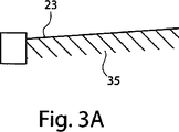
図1及び2は、横方向接続片15を有する刃フレーム10を含む、本発明の剃毛刃アセンブリのプリフォーム5を示す。刃フレーム10は、複数の剃毛刃部材35を収容するのに十分な長さの頂部6を備えるので、プリフォーム5を形成する上でのプラットフォームとして機能する。剃毛刃部材35は、接続片15の、各接続片の長さ方向の空間を占める、複数の対で対向する支持翼20(図5に示す)上に結合されている。剃毛刃部材は、特に、かかる結合を溶接により行う場合は、横方向接続片の芯強度を高めるため、中央の長手方向領域ではなく支持翼20に結合してもよい。頂部6の長手方向各端部には、剃毛刃部材35をその相対する端部36にて支持する垂直端部7が配置されている。横方向接続片15のそれぞれは、頂部6の一領域に接続された、又はこれと一体である、近位端部16を有する。横方向接続片15のそれぞれはまた、反対側に遠位端部17を有する。使い捨て締結部18は、これら遠位端部17それぞれの付近に、刃フレーム10の頂部6に平行となるように位置している。使い捨て締結部18は刃フレーム10の残りの部分を固定するよう機能して、剃毛刃部材35が連続して刃フレームに結合される際、坐屈又は歪曲が最小限となる、又は起こらないようにする。上述したように、剃毛刃部材は、図3Aに示すように通常剃刀カートリッジ内に存在するガードに対して特定の幾何形状を有していることが望ましい。同図は、連続的に配置された各剃毛刃部材の、ガード内の基準点により定められる高さに対する刃先23を示している。好ましくは、剃刀カートリッジは、米国特許第6212777号に詳述されるような、段階的な幾何形状を示す。しかし、剃毛刃部材がカートリッジハウジング内、この場合は刃フレーム内に組み入れられるとき、剃毛刃部材をフレームの長さに沿った位置に溶接した後に剃毛刃部材を連続してこの同じフレーム上に頂部6から段階的に離れるようにして、使い捨て締結部の位置に向けガードに近づくようにして溶接する結果として、刃フレームにより加わる力によって、もともと意図された幾何形状が悪影響を受けることが多々ある。使い捨て締結部18による固定によって自ずと、横方向接続片18それぞれの遠位端部が刃フレーム10全体の元の水平(X)面内に固定される。一般的には、剃毛刃部材を連続して刃フレームに結合していくと、刃フレームの装着前の状態(図3Bに示す)の元の水平(X)面から刃フレームの中央部分が上向きに上がり、刃フレーム全体が凹形状を帯びる傾向がある。結果として生じるこの凹形状によって、刃フレームの対向する垂直端部が更に引き込まれてしまう。このような意図しないフレームの変形から、剃毛刃部材を連続してフレームに結合していく際に、刃の幾何形状に悪影響を及ぼす結果となる。フレームの所定部分の曲げ及び切り取りにより更に変形が加わる可能性もある。したがって、使い捨て締結部は、設定された幾何形状から意図せずに外れることを防ぐ。
1 and 2 show a preform 5 of a shaving blade assembly of the present invention that includes a
剃毛刃部材が全て刃フレームに結合されてしまえば、使い捨て締結部及びその他追加の使い捨て部分はフレームから取り外してよい。この取り外しは、破砕、切削、レーザー加熱、及びこれらの組み合わせにより行うことができる。剃毛刃部材を刃フレームに結合し、横方向接続片の遠位端部を必要に応じて曲げると、同時係属中の米国特許出願第______号、「形状適合的湿式剃毛用剃刀」(ケビン・J・ウェイン(Kevin J. Wain)により2007年11月2日出願)内で説明されるカートリッジ内に組み込むのに好適な剃毛刃アセンブリが得られる。図4にも、横方向接続片の遠位端部の曲げ後、及び使い捨て締結部の取り外し後の、本発明によるプリフォームを示している。 Once all the shaving blade members are coupled to the blade frame, the disposable fasteners and other additional disposable parts may be removed from the frame. This removal can be performed by crushing, cutting, laser heating, and combinations thereof. When the shaving blade member is coupled to the blade frame and the distal end of the lateral connecting piece is bent as required, the co-pending U.S. Patent Application No. A shaving blade assembly suitable for incorporation into a cartridge as described in Kevin J. Wain filed Nov. 2, 2007) is obtained. FIG. 4 also shows the preform according to the invention after bending the distal end of the transverse connecting piece and after removing the disposable fastener.
プリフォームはこれに加えて、位置決め孔25を含んでもよいが、これに限られない。プリフォームは、カートリッジ製造中のプリフォーム処理の助けとなるよう、これらの孔を含んでもよい。具体的には、これらの孔は、製造過程においてプリフォームをある位置から別の位置に運ぶ溶接治具部の受容体として機能する。プリフォームはまた、フレームの様々な領域、及び頂部、垂直端部、遠位端部などの、それぞれの部分に、流出孔30を備えていてもよい。具体的な実施形態では、孔30が、フレームの頂部の長さに沿った、異なる領域に沿って複数設けることができる。これらの孔30は、溶融したカートリッジ材料がプリフォームの周囲に剃刀カートリッジとして形成される際に、加工後のプリフォーム(例えば、溶接後、曲げ後、及び/又は取り外し後)を「掴み」、保持するのに役立つ。孔により、カートリッジ形成体が固化する際に溶融材料が孔を通じて供給され孔内に残ることができ、それにより、カートリッジ材料に内包されてカートリッジ本体から簡単に外れないプリフォームを得ることができる。
In addition to this, the preform may include a
本明細書に開示されている寸法及び値は、列挙した正確な数値に厳しく制限されるものとして理解すべきではない。それよりむしろ、特に指定されない限り、こうした各寸法は、列挙された値とその値周辺の機能的に同等の範囲の両方を意味することを意図する。例えば、「40mm」として開示された寸法は、「約40mm」を意味することを意図する。 The dimensions and values disclosed herein are not to be understood as being strictly limited to the exact numerical values recited. Instead, unless otherwise specified, each such dimension is intended to mean both the recited value and a functionally equivalent range surrounding that value. For example, a dimension disclosed as “40 mm” is intended to mean “about 40 mm”.
「発明を実施するための形態」で引用した全ての文献は、関連部分において本明細書に参考として組み込まれるが、いずれの文献の引用も、それが本発明に関して先行技術であることを容認するものとして解釈すべきではない。本明細書中の用語の任意の意味又は定義が、参照により組み込まれた文献中の同一の用語の任意の意味又は定義と相反する限りにおいては、本明細書においてその用語に与えられた意味又は定義が適用されるものとする。 All documents cited in “Mode for Carrying Out the Invention” are incorporated herein by reference in the relevant part, and any citation of any document admits that it is prior art with respect to the present invention. It should not be interpreted as a thing. To the extent that any meaning or definition of a term in this specification contradicts any meaning or definition of the same term in a document incorporated by reference, the meaning or The definition shall apply.
本発明の特定の諸実施形態を図示し、記載したが、本発明の趣旨及び範囲から逸脱することなく他の様々な変更及び修正を実施できることが当業者には自明である。したがって、本発明の範囲内にあるそのような全ての変更及び修正を添付の特許請求の範囲で扱うものとする。 While particular embodiments of the present invention have been illustrated and described, it would be obvious to those skilled in the art that various other changes and modifications can be made without departing from the spirit and scope of the invention. Accordingly, it is intended to cover in the appended claims all such changes and modifications that are within the scope of this invention.
Claims (9)
b.前記刃フレームに溶接され、前記フレームの長さに沿って前記横方向接続片にかけられた、複数の刃と、
c.前記複数の刃と平行に、かつ前記横方向接続片を横切るよう配置された使い捨て締結部と、
を備え、
前記使い捨て締結部は、前記フレームを剃刀カートリッジ内に組み込む前に取り外される
ことを特徴とする、剃毛刃アセンブリのプリフォーム。a. A blade frame with lateral connection pieces;
b. A plurality of blades welded to the blade frame and hung on the lateral connection piece along the length of the frame;
c. A disposable fastening portion disposed in parallel with the plurality of blades and across the lateral connection piece;
Equipped with a,
A preform for a shaving blade assembly, wherein the disposable fastener is removed prior to incorporating the frame into a razor cartridge .
Applications Claiming Priority (3)
| Application Number | Priority Date | Filing Date | Title |
|---|---|---|---|
| US161607P | 2007-11-02 | 2007-11-02 | |
| US61/001,616 | 2007-11-02 | ||
| PCT/IB2008/054517 WO2009057067A1 (en) | 2007-11-02 | 2008-10-30 | Razor blade assembly pre-form |
Publications (2)
| Publication Number | Publication Date |
|---|---|
| JP2011500254A JP2011500254A (en) | 2011-01-06 |
| JP5117573B2 true JP5117573B2 (en) | 2013-01-16 |
Family
ID=40328420
Family Applications (1)
| Application Number | Title | Priority Date | Filing Date |
|---|---|---|---|
| JP2010530621A Expired - Fee Related JP5117573B2 (en) | 2007-11-02 | 2008-10-30 | Razor blade assembly preform |
Country Status (10)
| Country | Link |
|---|---|
| US (1) | US8650758B2 (en) |
| EP (1) | EP2219829B1 (en) |
| JP (1) | JP5117573B2 (en) |
| KR (1) | KR20100083162A (en) |
| CN (1) | CN101861236B (en) |
| MX (1) | MX2010004764A (en) |
| PL (1) | PL2219829T3 (en) |
| RU (1) | RU2460634C2 (en) |
| TW (1) | TW200940289A (en) |
| WO (1) | WO2009057067A1 (en) |
Families Citing this family (28)
| Publication number | Priority date | Publication date | Assignee | Title |
|---|---|---|---|---|
| US7272991B2 (en) * | 2004-02-09 | 2007-09-25 | The Gillette Company | Shaving razors, and blade subassemblies therefor and methods of manufacture |
| JP4977374B2 (en) * | 2006-02-14 | 2012-07-18 | 株式会社貝印刃物開発センター | razor |
| JP4950506B2 (en) * | 2006-02-14 | 2012-06-13 | 株式会社貝印刃物開発センター | razor |
| JP4950507B2 (en) * | 2006-02-14 | 2012-06-13 | 株式会社貝印刃物開発センター | razor |
| US20100175261A1 (en) * | 2008-07-22 | 2010-07-15 | L.I.F.E. Support Technologies, Llc | Safety razor |
| US20110203112A1 (en) * | 2008-07-22 | 2011-08-25 | Samuel Lax | Safety razor |
| CN103962764B (en) * | 2014-05-09 | 2016-04-20 | 任向荣 | Thin slice automatic soldering method |
| WO2017041845A1 (en) * | 2015-09-09 | 2017-03-16 | Beiersdorf Aktiengesellschaft | Safety razor and blade unit for safety razor |
| JP6548328B2 (en) * | 2015-09-15 | 2019-07-24 | 株式会社貝印刃物開発センター | Safety razor |
| USD794871S1 (en) | 2016-01-15 | 2017-08-15 | Medline Industries, Inc. | Clipper |
| USD795497S1 (en) | 2016-01-15 | 2017-08-22 | Medline Industries, Inc. | Clipper |
| USD816906S1 (en) * | 2016-03-18 | 2018-05-01 | Personal Care Marketing and Research International | Razor cartridge |
| BR112018068899A2 (en) | 2016-03-18 | 2019-01-22 | Personal Care Marketing And Res Inc | razor blade cartridge |
| USD816907S1 (en) * | 2016-03-18 | 2018-05-01 | Personal Care Marketing and Research International | Razor frame |
| USD816905S1 (en) * | 2016-03-18 | 2018-05-01 | Personal Care Marketing and Research International | Razor cartridge |
| USD802217S1 (en) | 2016-06-10 | 2017-11-07 | Medline Industries, Inc. | Clipper head |
| USD802214S1 (en) | 2016-06-10 | 2017-11-07 | Medline Industries, Inc. | Clipper head |
| USD802215S1 (en) | 2016-06-10 | 2017-11-07 | Medline Industries, Inc. | Clipper head |
| USD802216S1 (en) | 2016-06-10 | 2017-11-07 | Medline Industries, Inc. | Clipper head |
| US9993931B1 (en) | 2016-11-23 | 2018-06-12 | Personal Care Marketing And Research, Inc. | Razor docking and pivot |
| CN106625792A (en) * | 2017-02-27 | 2017-05-10 | 贵州裕隆实业有限公司 | Blade support of shaver and blade assembly |
| CN110621459A (en) * | 2017-06-16 | 2019-12-27 | 比克维奥莱克斯公司 | Razor cartridge |
| USD884970S1 (en) | 2019-02-27 | 2020-05-19 | PCMR International Ltd. | Razor cartridge guard |
| USD884969S1 (en) | 2019-02-27 | 2020-05-19 | Pcmr International Ltd | Combined razor cartridge guard and docking |
| USD884971S1 (en) | 2019-02-27 | 2020-05-19 | Pcmr International Ltd | Razor cartridge |
| KR102292824B1 (en) * | 2019-09-20 | 2021-08-25 | 주식회사 도루코 | Razor Cartridge and Manufacturing Method Thereof |
| KR102343058B1 (en) * | 2019-12-10 | 2021-12-24 | 주식회사 도루코 | Razor Cartridge |
| US11000960B1 (en) | 2020-11-16 | 2021-05-11 | Personal Care Marketing And Research, Inc. | Razor exposure |
Family Cites Families (28)
| Publication number | Priority date | Publication date | Assignee | Title |
|---|---|---|---|---|
| US1713079A (en) * | 1928-10-17 | 1929-05-14 | Jr William F Hall | Safety razor |
| US3816913A (en) | 1972-10-03 | 1974-06-18 | Warner Lambert Co | Razor with adjustable blade cartridge |
| US3889369A (en) * | 1974-12-13 | 1975-06-17 | Warner Lambert Co | Shaving unit for safety razor |
| US4227302A (en) | 1979-01-05 | 1980-10-14 | Torrance William L | Shaving apparatus |
| US4253236A (en) | 1979-06-19 | 1981-03-03 | The Gillette Company | Razor blade assembly |
| NL8200101A (en) * | 1982-01-13 | 1983-08-01 | Philips Nv | SHAVER. |
| US5104605A (en) | 1987-04-24 | 1992-04-14 | Warner-Lambert Company | Process for insert molding disposable razor |
| GB8710963D0 (en) * | 1987-05-08 | 1987-06-10 | Gillette Co | Safety razors |
| AU638974B2 (en) | 1989-06-05 | 1993-07-15 | Warner-Lambert Company | Razor mechanism |
| US5388332A (en) | 1990-10-22 | 1995-02-14 | The Gillette Company | Razor blade units and blade spacers therefor |
| US5236439A (en) | 1992-02-25 | 1993-08-17 | Warner-Lambert Company | Razor cartridge with improved rinsability |
| GB9208098D0 (en) | 1992-04-13 | 1992-05-27 | Gillette Co | Razor with movable cartridge |
| US6212777B1 (en) * | 1993-09-29 | 2001-04-10 | The Gillette Company | Safety razors |
| US6173498B1 (en) | 1996-08-05 | 2001-01-16 | The Gillette Company | Razor |
| US5822862A (en) | 1997-01-17 | 1998-10-20 | Warner-Lambert Co. | Suspended blade shaving system |
| WO2001039937A1 (en) * | 1999-11-29 | 2001-06-07 | Koninklijke Philips Electronics N.V. | Shaver provided with a shaving head having a sub-frame and a main frame |
| US20020023352A1 (en) | 2000-02-18 | 2002-02-28 | Samson Mil'shtein | Razor cartridge with enhanced access to wrinkled and curved skin surfaces |
| US6804886B2 (en) * | 2000-10-16 | 2004-10-19 | The Gillette Company | Safety razors |
| US20040020053A1 (en) | 2000-10-16 | 2004-02-05 | The Gillette Company | Safety razors |
| GB0025339D0 (en) * | 2000-10-16 | 2000-11-29 | Gillette Co | Safety razors |
| EP2017044A1 (en) | 2001-04-27 | 2009-01-21 | Eveready Battery Company, Inc. | Wet razor with four blades, and cartridge therefor |
| US20050015991A1 (en) | 2002-04-24 | 2005-01-27 | Eveready Battery Company, Inc. | Razor cartridge |
| US6839968B2 (en) | 2002-05-09 | 2005-01-11 | The Gillette Company | Shaving systems |
| EP1597028B1 (en) | 2003-02-19 | 2010-06-09 | Eveready Battery Company, Inc. | Multiple blade razor cartridge |
| US20060218794A1 (en) | 2005-04-05 | 2006-10-05 | Eveready Battery Company, Inc. | Razor cartridge |
| US20070056167A1 (en) | 2005-09-14 | 2007-03-15 | Eveready Battery Company, Inc. | Blade mounting members for a razor cartridge |
| JP4950507B2 (en) * | 2006-02-14 | 2012-06-13 | 株式会社貝印刃物開発センター | razor |
| GB0615113D0 (en) * | 2006-07-28 | 2006-09-06 | Gillette Co | Wet razor with conforming blade support |
-
2008
- 2008-10-29 US US12/260,407 patent/US8650758B2/en active Active
- 2008-10-30 EP EP08844476.5A patent/EP2219829B1/en active Active
- 2008-10-30 CN CN2008801139917A patent/CN101861236B/en not_active Expired - Fee Related
- 2008-10-30 MX MX2010004764A patent/MX2010004764A/en active IP Right Grant
- 2008-10-30 WO PCT/IB2008/054517 patent/WO2009057067A1/en active Application Filing
- 2008-10-30 PL PL08844476T patent/PL2219829T3/en unknown
- 2008-10-30 RU RU2010117002/02A patent/RU2460634C2/en not_active IP Right Cessation
- 2008-10-30 JP JP2010530621A patent/JP5117573B2/en not_active Expired - Fee Related
- 2008-10-30 KR KR1020107009697A patent/KR20100083162A/en not_active Application Discontinuation
- 2008-10-31 TW TW097142243A patent/TW200940289A/en unknown
Also Published As
| Publication number | Publication date |
|---|---|
| WO2009057067A1 (en) | 2009-05-07 |
| EP2219829A1 (en) | 2010-08-25 |
| US20090113716A1 (en) | 2009-05-07 |
| US8650758B2 (en) | 2014-02-18 |
| RU2010117002A (en) | 2011-12-10 |
| MX2010004764A (en) | 2010-06-01 |
| CN101861236A (en) | 2010-10-13 |
| EP2219829B1 (en) | 2014-03-26 |
| CN101861236B (en) | 2013-02-13 |
| KR20100083162A (en) | 2010-07-21 |
| JP2011500254A (en) | 2011-01-06 |
| PL2219829T3 (en) | 2014-08-29 |
| TW200940289A (en) | 2009-10-01 |
| RU2460634C2 (en) | 2012-09-10 |
Similar Documents
| Publication | Publication Date | Title |
|---|---|---|
| JP5117573B2 (en) | Razor blade assembly preform | |
| JP6665122B2 (en) | Blade set, hair cutting device, and related manufacturing method | |
| EP2349658B1 (en) | Razor cartridges with perforated blade assemblies | |
| US9193080B2 (en) | Shaving blade unit with self-leveling trimmer | |
| EP2866982B1 (en) | Shaving razor cartridge | |
| US7681314B2 (en) | Inter-blade guard and method for manufacturing same | |
| JP6395848B2 (en) | Shaving blade cartridge, shaver comprising such a shaving blade cartridge, and method of manufacturing such a shaving blade cartridge | |
| JP5384729B2 (en) | Comb guard for shaving razor trimming blade | |
| JP5719755B2 (en) | Safety razor | |
| EP2008780A1 (en) | Shaving razor with additional trimming blade | |
| CN111836705B (en) | Razor cartridge | |
| CN104440969A (en) | A shaving blade cartridge | |
| US20100218381A1 (en) | Inter-Blade Guard and Method For Manufacturing Same | |
| US20060218794A1 (en) | Razor cartridge | |
| WO2008128152A9 (en) | Multi-use shaving implement | |
| US11318632B2 (en) | Razor system | |
| KR20080056742A (en) | Method for manufacturing razor blades | |
| GB2139541A (en) | A razor | |
| JP2009018056A (en) | Edge for reciprocating electric razor | |
| CN101842196B (en) | Conforming wet shaving razor | |
| EP1896224A1 (en) | Razor cartridge | |
| KR20070016942A (en) | Flat Manual Hair Trimmer | |
| JP2006296614A (en) | Razor |
Legal Events
| Date | Code | Title | Description |
|---|---|---|---|
| A131 | Notification of reasons for refusal |
Free format text: JAPANESE INTERMEDIATE CODE: A131 Effective date: 20120529 |
|
| A977 | Report on retrieval |
Free format text: JAPANESE INTERMEDIATE CODE: A971007 Effective date: 20120531 |
|
| A521 | Written amendment |
Free format text: JAPANESE INTERMEDIATE CODE: A523 Effective date: 20120829 |
|
| TRDD | Decision of grant or rejection written | ||
| A01 | Written decision to grant a patent or to grant a registration (utility model) |
Free format text: JAPANESE INTERMEDIATE CODE: A01 Effective date: 20120921 |
|
| A01 | Written decision to grant a patent or to grant a registration (utility model) |
Free format text: JAPANESE INTERMEDIATE CODE: A01 |
|
| A61 | First payment of annual fees (during grant procedure) |
Free format text: JAPANESE INTERMEDIATE CODE: A61 Effective date: 20121017 |
|
| R150 | Certificate of patent or registration of utility model |
Free format text: JAPANESE INTERMEDIATE CODE: R150 |
|
| FPAY | Renewal fee payment (event date is renewal date of database) |
Free format text: PAYMENT UNTIL: 20151026 Year of fee payment: 3 |
|
| LAPS | Cancellation because of no payment of annual fees |