JP5116750B2 - LOCATION METHOD, POSITIONING SYSTEM, AND PROGRAM - Google Patents
LOCATION METHOD, POSITIONING SYSTEM, AND PROGRAM Download PDFInfo
- Publication number
- JP5116750B2 JP5116750B2 JP2009255046A JP2009255046A JP5116750B2 JP 5116750 B2 JP5116750 B2 JP 5116750B2 JP 2009255046 A JP2009255046 A JP 2009255046A JP 2009255046 A JP2009255046 A JP 2009255046A JP 5116750 B2 JP5116750 B2 JP 5116750B2
- Authority
- JP
- Japan
- Prior art keywords
- distance
- terminal
- communication
- communication terminal
- reference terminal
- Prior art date
- Legal status (The legal status is an assumption and is not a legal conclusion. Google has not performed a legal analysis and makes no representation as to the accuracy of the status listed.)
- Active
Links
Images


Description
本発明は、位置特定方法、測位システム及びプログラムに関し、更に詳しくは、通信端末の位置を特定するための位置特定方法、測位システム及びプログラムに関する。 The present invention relates to a position specifying method, a positioning system, and a program, and more particularly, to a position specifying method, a positioning system, and a program for specifying the position of a communication terminal.
物体の位置を検出する測位システムとして知られているGPS(Global Positioning System)は、例えば屋内など、衛星からの電波が受信できない環境では利用することができない。そこで、屋内などの環境下では、電波を用いた測位システムが用いられる。 A GPS (Global Positioning System) known as a positioning system for detecting the position of an object cannot be used in an environment where radio waves from satellites cannot be received, such as indoors. Therefore, a positioning system using radio waves is used in an indoor environment.
この種のシステムは、通信端末から発信された電波が測位端末に到達するまでの時間を利用して無線通信端末と測位端末との間の距離を計測する方法や、測位端末に到達した電波の減衰量に基づいて無線通信端末と測位端末との間の距離を計測する方法などを用いて、通信端末の位置を特定する(例えば特許文献1参照)。 This type of system uses a method for measuring the distance between a wireless communication terminal and a positioning terminal using the time it takes for the radio wave transmitted from the communication terminal to reach the positioning terminal. The position of the communication terminal is specified using a method of measuring the distance between the wireless communication terminal and the positioning terminal based on the attenuation (see, for example, Patent Document 1).
しかしながら、上述した測位システムでは、マルチパスにより測位精度が低下するという課題がある。 However, the positioning system described above has a problem that positioning accuracy is reduced due to multipath.
例えば、電波の到達時間を利用して距離を計測する際に、反射波のみが測位端末に到達すると、計測された通信端末と測位端末との距離が、実際の距離よりも大きくなってしまう。その理由は、反射波の経路が、実際の通信端末と測位端末との距離よりも長くなるためである。 For example, when measuring the distance using the arrival time of radio waves, if only the reflected wave reaches the positioning terminal, the measured distance between the communication terminal and the positioning terminal becomes larger than the actual distance. This is because the reflected wave path is longer than the distance between the actual communication terminal and the positioning terminal.
また、電波の減衰量に基づいて距離を算出する方法を用いたい場合に、直接波と反射波とが干渉すると、算出された通信端末と測位端末との距離が、実際の距離より著しく短くなったり或いは長くなったりすることがある。 In addition, if you want to use a method that calculates distance based on the amount of radio wave attenuation, if the direct wave and reflected wave interfere, the calculated distance between the communication terminal and the positioning terminal will be significantly shorter than the actual distance. Or it may be longer.
上述した計測距離と実際の距離との誤差は、反射波に起因するものである。このため、電波を使用する環境が同じであるときには、計測した距離に常に一定の誤差が含まれる。したがって、距離を複数回に渡り計測した結果の平均値や分散を利用しても、計測距離に含まれる誤差の割合を予想するのは困難である。 The error between the measurement distance and the actual distance described above is caused by the reflected wave. For this reason, when the environment where radio waves are used is the same, the measured distance always includes a certain error. Therefore, it is difficult to predict the ratio of errors included in the measured distance even if the average value or variance of the results obtained by measuring the distance multiple times is used.
そこで、マルチパスが起こり得る環境下においても、精度よく測位を行うことを可能とするシステムが種々提案されている(例えば特許文献2参照)。 Thus, various systems have been proposed that enable accurate positioning even in an environment where multipath can occur (see, for example, Patent Document 2).
特許文献2に記載されたシステムは、複数のアンテナを有する移動局と、この移動局と無線通信を行う基地局とから構成されている。このシステムは、移動局の複数のアンテナを介して出力された電波それぞれのマルチパス特性の相違に基づいて、マルチパスによる誤差を特定し、移動局と基地局との相対位置を精度よく検出しようとするものである。
The system described in
しかしながら、マルチパスが発生しやすい状況下では、基地局に到達する電波相互間のマルチパス特性の差はわずかでしかない。この場合には、マルチパスによる誤差を効果的に低減することが困難となる場合がある。また、本システムでは、電波を出力するためのアンテナが複数本必要になる。このため、装置の製造コストが高くなるといった不都合も考えられる。 However, in a situation where multipath is likely to occur, there is only a slight difference in multipath characteristics between radio waves reaching the base station. In this case, it may be difficult to effectively reduce errors due to multipath. In addition, this system requires a plurality of antennas for outputting radio waves. For this reason, the problem that the manufacturing cost of an apparatus becomes high can also be considered.
本発明は、上述の事情の下になされたものであり、マルチパスによる計測誤差の影響を低減し、精度よく通信端末の位置を特定することを目的とする。 The present invention has been made under the circumstances described above, and it is an object of the present invention to reduce the influence of measurement errors due to multipath and to accurately identify the position of a communication terminal.
上記目的を達成するため、本発明の位置特定方法は、所定の範囲に存在する通信端末と、複数の基準位置との間の距離に基づいて、通信端末の位置を特定するための位置特定方法であって、基準位置にそれぞれ配置された基準端末と、通信端末との通信結果に基づいて、通信端末と基準端末との間の第1距離を計測する工程と、通信端末の、所定の範囲における仮定の位置を順次決定する工程と、基準端末と仮定の位置との間の第2距離を順次算出する工程と、第1距離と第2距離との差が、所定の閾値よりも大きい場合にほぼ零となる値を出力し、それ以外の場合に第1距離と第2距離との差に応じた値を出力する評価関数を用いた演算を行う工程と、演算により、基準端末毎に算出された値の合計が最も大きいときの仮定の位置を、通信端末の位置として特定する工程とを含む。 In order to achieve the above object, a position specifying method of the present invention is a position specifying method for specifying a position of a communication terminal based on distances between a communication terminal existing in a predetermined range and a plurality of reference positions. A step of measuring a first distance between the communication terminal and the reference terminal based on a communication result between the reference terminal and the communication terminal respectively arranged at the reference position, and a predetermined range of the communication terminal If the difference between the first distance and the second distance is greater than a predetermined threshold, the step of sequentially determining the assumed position in the step, the step of sequentially calculating the second distance between the reference terminal and the assumed position For each reference terminal by performing a calculation using an evaluation function that outputs a value that is substantially zero in the other case, and otherwise outputs a value corresponding to the difference between the first distance and the second distance. Communication of the assumed position when the sum of the calculated values is the largest And a step of identifying as end position.
本発明によれば、測定結果に含まれる誤差が大きいと考えられる場合には、当該測定結果が除外され、信頼性の高い計測結果のみに基づいて、通信端末の位置が特定される。このため、マルチパスによって計測距離に誤差が生じたとしても、精度よく通信端末の位置を測位することができる。 According to the present invention, when it is considered that the error included in the measurement result is large, the measurement result is excluded, and the position of the communication terminal is specified based only on the highly reliable measurement result. For this reason, even if an error occurs in the measurement distance due to multipath, the position of the communication terminal can be measured with high accuracy.
《第1の実施形態》
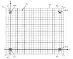
以下、本発明の第1の実施形態を、図面を参照しつつ説明する。図1は、本実施形態に係る測位システム10の概略的な構成を示す図である。測位システム10は、多数のユーザによって共有されるスペース30を利用するユーザ51の位置を測位するためのシステムである。
<< First Embodiment >>
Hereinafter, a first embodiment of the present invention will be described with reference to the drawings. FIG. 1 is a diagram illustrating a schematic configuration of a
図1に示されるように、測位システム10は、ユーザ51に所持される通信端末11Aと、スペース30の4角近傍にそれぞれ配置された4つの基準端末211〜214とを有している。
As shown in FIG. 1, the
図2は、通信端末11Aのブロック図である。図2に示されるように、通信端末11Aは、CPU(Central Processing Unit)11a、主記憶部11b、補助記憶部11c、及び通信ユニット11dを有している。
FIG. 2 is a block diagram of the
CPU11aは、補助記憶部11cに記憶されているプログラムにしたがって、基準端末211〜214それぞれと無線通信を行う。そして、無線通信の結果に基づいて、通信端末11Aのスペース30における位置を特定する。なお、位置を特定するための手順については後述する。
The
主記憶部11bは、RAM(Random Access Memory)等を含んで構成され、CPU11aの作業領域として用いられる。
The
補助記憶部11cは、ROM(Read Only Memory)、半導体メモリ等の不揮発性メモリを含んで構成されている。この補助記憶部11cは、CPU11aが実行するプログラム、及び基準端末211〜214のスペース30における位置情報などを記憶している。また、CPU11aの演算結果などを含む情報を逐次記憶する。
The
通信ユニット11dは、UWB(Ultra Wide Band)方式の通信を行う通信インターフェイスなどを含んで構成されている。CPU11aは、この通信ユニット11dを介して、基準端末211〜214それぞれと無線通信を行う。
The
図3は、基準端末211のブロック図である。図3に示されるように、基準端末211は、通信端末11Aと同様に、CPU21a、主記憶部21b、補助記憶部21c、及び通信ユニット21dを有している。
Figure 3 is a block diagram of a
この基準端末211の補助記憶部21cには、CPU21aが実行するプログラムと、通信端末毎に割り当てられた識別IDなどの識別情報が記憶されている。CPU21aは、補助記憶部21cに記憶されているプログラムにしたがって、通信端末11Aと通信を行う。
This
基準端末212〜214も、基準端末211と同等の構成を有している。そして、基準端末212〜214を構成するCPU21aは、通信ユニット21dを介して、通信端末11Aと通信を行う。
The
本測位システム10では、通信端末11Aと基準端末211〜214とが協働することにより、通信端末11Aの、スペース30における位置が測位される。以下、通信端末11A及び基準端末211〜214の動作について、図4及び図5に示されるフローチャートを参照しつつ説明する。なお、前提として、通信端末11Aと、基準端末211〜214それぞれの間の通信が確立しているものとする。
In the
通信端末11AのCPU11aは、まず、基準端末211に対して、測距要求信号を送信する(ステップS101)。ここで、基準端末211に送信する測距要求信号を、測距要求信号S(1)と表示する。また、各基準端末212〜214に送信する測距要求信号を、それぞれ測距要求信号S(2)〜S(4)と表示する。
基準端末211は、測距要求信号S(1)を受信すると、識別IDを含む信号(応答信号)を送信する(ステップS201)。以下、基準端末211から送信される応答信号を、応答信号ID(1)と表示する。また、各基準端末212〜214から送信される応答信号を、応答信号ID(2)〜ID(4)と表示する。
CPU11aは、基準端末211から送信された応答信号ID(1)を受信すると、電磁波が通信端末11Aと基準端末211との間を往復するために要した時間(所用時間)を算出する。例えば、CPU11aは、測距要求信号S(1)を送信した時刻t1から、応答信号ID(1)を受信した時刻t4までの時間T1を算出する。次に、この時間T1から、基準端末211が測距要求信号S(1)を受信してから応答信号ID(1)を送信するまでの処理時間T3を減ずる。
CPU11a, when the
この処理時間T3は、基準端末211が、信号処理を行うのに要する時間である。このため、基準端末211と通信端末11Aとの距離に依存して変動することはなく、常に一定である。CPU11aは、時間T1から処理時間T3を減ずることで、電磁波が通信端末11Aから基準端末211に到達するのに要する時間T2と、電磁波が基準端末211から通信端末11Aに到達するのに要する時間T4との和を、応答時間RT(=T2+T4)として算出する(ステップS102)。なお、この処理時間T3は、基準端末211〜214相互間でほぼ等しく、予め計測され、通信端末11Aの補助記憶部11cに記憶されている。また、各時間の計測は、例えばCPU11aが備えるカウンタなどを用いて行うことができる。
The treatment time T3, the
一般に、電磁波の伝搬速度Vは光速と等価である。このため、通信端末11Aを所持するユーザ51が、スペース30の内部を移動していたとしても、通信端末11Aから基準端末211に電磁波が到達するまでの時間と、基準端末211から通信端末11Aに電磁波が到達する時間とは、ほぼ等しいといえる。そこで、CPU11aは、次式(1)に示されるように、電磁波の伝搬速度Vと、応答時間RTを2で除したものとを乗じて、通信端末11Aと基準端末211との計測距離MD(1)を算出する(ステップS103)。
In general, the propagation speed V of electromagnetic waves is equivalent to the speed of light. For this reason, even if the
MD(1)=V×(RT/2) …(1) MD (1) = V × (RT / 2) (1)
以降、CPU11aは、上述と同様の手順で、通信端末11Aと、基準端末212〜214それぞれとの計測距離MD(2),MD(3),MD(4)を算出する(ステップS104〜S112)。また、基準端末212〜214それぞれは、通信端末11Aからの測距要求信号S(2)〜S(4)に応じて、応答信号ID(2)〜ID(4)を送信する(ステップS202〜S204)。
Thereafter, the
次に、CPU11aは、図6に示されるように、スペース30に、基準端末211を原点とするXY座標系と、X軸及びY軸に平行なグリッド線を規定する。ここでは、CPU11aは、一例として、XY座標系と、Y軸に沿って等間隔に配置された20本のグリッド線と、X軸に沿って等間隔に配置された25本のグリッド線とを規定する(ステップS113)。これにより、スペース30には、X軸及びY軸と、グリッド線とで546個の点PM(M=1、2…546)が規定される。
Then,
次に、CPU11aは、546個の点PMをそれぞれ選択し、基準端末211〜214の中心と一致する点P(1)〜P(4)それぞれと、選択した点PMとの計算距離CDM(1),CDM(2),CDM(3),CDM(4)をそれぞれ算出する(ステップS114)。
Then,
次に、CPU11aは、各点PMについて、算出した計算距離CDM(i)及び計測距離MD(i)を変数とする評価関数E(PM,MD(i))を用いた演算を行う。なお、iは1から4までの整数である。評価関数E(PM,MD(i))は、計測距離MD(i)が、点PMの位置に対して適当である場合に、値が大きくなり、適当でない場合に値がほぼ零となる関数である。この評価関数E(PM,MD(i))は、例えば次式(2)で示される。なお、σi 2は、直接波を用いて通信端末11Aと基準端末211〜214との間の距離を計測したときの誤差の分散である。
Next, the

図7は、計算距離CDM(i)が7.5mであるときの、評価関数E(PM,MD(i))の特性を示す図である。この図は、相互に直交する2本の横軸それぞれが、X軸方向及びY軸方向の距離を表し、縦軸が評価関数E(PM,MD(i))の算出結果を表している。この評価関数E(PM,MD(i))の算出結果は、計測距離MD(i)が計算距離CD(i)と等しい7.5mのときにピークになり、計測距離MD(i)が、7.5mから大きくなるにしたがって、或いは小さくなるにしたがって、急峻に小さくなりほぼ零になる。 FIG. 7 is a diagram illustrating characteristics of the evaluation function E (P M , MD (i)) when the calculation distance CD M (i) is 7.5 m. In this figure, each of the two horizontal axes orthogonal to each other represents the distance in the X-axis direction and the Y-axis direction, and the vertical axis represents the calculation result of the evaluation function E (P M , MD (i)). . The calculation result of the evaluation function E (P M , MD (i)) has a peak when the measurement distance MD (i) is 7.5 m which is equal to the calculation distance CD (i), and the measurement distance MD (i) is As the distance increases from 7.5 m or decreases, the distance decreases steeply and becomes almost zero.
CPU11aは、次式(3)に示されるように、計測距離MD(1),MD(2),MD(3),MD(4)について、この評価関数E(PM,MD(i))を用いた演算を施す。そして、それぞれの計測距離MD(1)〜MD(4)についての演算結果ER(1),ER(2),ER(3),ER(4)の和を判定値ETMとして算出する(ステップS115)。なお、kは、基準端末211〜214の総数であり、ここでは4である。
As shown in the following expression (3), the
CPU11aは、各点PMについて、判定値ETMをそれぞれ算出すると、最も判定値ETMが大きいときの点PMを、通信端末11Aのスペース30における位置と特定する(ステップS116)。
CPU11a, for each point P M, calculating the judgment value ET M respectively, a point P M when the most determined value ET M is large, identifies the location in
例えば、図8の表に示されるように、基準端末211〜214それぞれのXY座標系における位置座標が(0,0)、(12,0)、(0,10)、(12,10)であり、計測距離MD(1)〜MD(4)がそれぞれ、10.34m、7.10m、8.87m、7.86mであった場合を考える。なお、ここでは、各計測距離MD(1)〜MD(4)のうち、計測距離MD(1)〜MD(3)は、直接波に基づいて計測された値であり、計測距離MD(4)は、例えばスペース30を包囲する壁などに反射された反射波に基づいて計測された値である。
For example, as shown in the table of FIG. 8, the position coordinates in the XY coordinate system of each of the
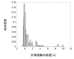
図9には、横軸を計測距離の誤差とし、縦軸を相対度数とするグラフが示されている。マルチパスによる計測距離の誤差は、壁面や障害物などに反射された電磁波(反射波)によって計測距離が求められることに起因するものである。このため、図9を参照するとわかるように、距離誤差はそのほとんどがプラス側に現れる。この理由から、マルチパスによる影響を受けて計測された計測距離MD(4)の値は、直接波に基づいて計測された計測距離よりも大きな値となっている。この値は、当然に実際の通信端末11Aと基準端末214との距離よりも大きくなる。
FIG. 9 shows a graph in which the horizontal axis is the measurement distance error and the vertical axis is the relative frequency. The error in the measurement distance due to the multipath is due to the fact that the measurement distance is obtained by the electromagnetic wave (reflected wave) reflected on the wall surface or obstacle. Therefore, as can be seen with reference to FIG. 9, most of the distance error appears on the plus side. For this reason, the value of the measurement distance MD (4) measured under the influence of the multipath is larger than the measurement distance measured based on the direct wave. This value is larger than the distance between the naturally
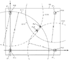
本実施形態では、上述のような計測距離MD(1)〜MD(4)が得られた場合には、図10に示されるように、半径をそれぞれ計測距離MD(1)〜MD(4)とする円C(1)〜C(4)のうち、円C(4)を除く円C(1)〜C(3)の交点とほぼ一致する点Po1が、スペース30における通信端末11Aの位置として特定される。
In the present embodiment, when the measurement distances MD (1) to MD (4) as described above are obtained, as shown in FIG. 10, the radii are measured distances MD (1) to MD (4), respectively. Of the circles C (1) to C (4), the point Po1 that substantially coincides with the intersection of the circles C (1) to C (3) excluding the circle C (4) is the position of the
評価関数Eを用いた演算の演算結果ER(1)〜ER(4)は、マルチパスの影響で実際の値よりも大きくなっていると考えられる計測距離が変数となったときに、ほぼ零となる。このため、最終的に算出される判定値ETMは、マルチパスの影響を受けないものとなる。したがって、この判定値ETMを用いて、精度よく点PMと通信端末11Aとの位置を特定することが可能となる。以下、その理由を、従来の方法で検出した結果を引用しつつ説明する。
The calculation results E R (1) to E R (4) of the calculation using the evaluation function E are variables when the measurement distance that is considered to be larger than the actual value due to the influence of multipath becomes a variable. Nearly zero. Therefore, the determination value ET M that is finally calculated, becomes not affected by multipath. Thus, by using this judgment value ET M, it is possible to specify the position of the precisely the point P M and the
一例として、図10には、従来の方法で特定された通信端末11Aの位置を表す点Po2が示されている。この点Po2は、次式(4)で表される演算結果としての判定値ETMが最小となるときの点である。
As an example, FIG. 10 shows a point Po2 representing the position of the
最小二乗法を用いた演算では、式(4)を参照するとわかるように、判定値ETMが、すべての計測距離MD(1)〜MD(4)に基づいて算出される。このため、計測距離MD(1)〜MD(4)の値に、マルチパスによる誤差が含まれる場合には、この誤差を含んだ計測距離に基づいて、通信端末11Aの位置が特定される。例えば、図10を参照するとわかるように、計測距離MD(4)に含まれる誤差の影響で、通信端末11Aの位置が、基準端末214から離れた方向へずれた状態で特定される。
In the calculation using the least squares method, as can be seen with reference to Equation (4), the determination value ET M is calculated based on all of the measurement distance MD (1) to MD (4). For this reason, when an error due to multipath is included in the values of the measurement distances MD (1) to MD (4), the position of the
一方、本実施形態では、マルチパスによる誤差を含む計測距離MD(4)が除外されたうえで、通信端末11Aの位置が特定される。例えば、図10を参照するとわかるように、マルチパスによる誤差を含まない計測距離MD(1)〜MD(3)のみに基づいて、通信端末11Aの位置が特定される。したがって、本実施形態に係る測位システム10では、従来の方法に比べて、通信端末11Aの位置がより精度よく特定される。
On the other hand, in the present embodiment, the measurement distance MD (4) including an error due to multipath is excluded, and the position of the
以上説明したように、本実施形態では、マルチパスの影響を受けることなく、通信端末11Aのスペース30における位置を精度よく特定することができる。
As described above, in the present embodiment, the position of the
また、本実施形態では、通信端末11Aは、定期的に図4及び図5に示される処理を実行することで、スペース30を移動するユーザ51の位置をリアルタイムに検出することが可能となる。
In the present embodiment, the
また、本実施形態では、測距要求信号S(i)を送信した時刻から、応答信号ID(i)を受信した時刻までの時間T1から、基準端末211〜214での処理時間T3を減ずることで、応答時間RTを求めた。これに限らず、測距要求信号S(i)が送信された時刻から、測距要求信号S(i)が受信された時刻までの時間と、応答信号ID(i)が送信された時刻から、応答信号ID(i)が受信された時刻までの時間を直接計測することとしてもよい。
Further, in the present embodiment, from the time that has transmitted the ranging request signal S (i), from the time T1 until time of receiving the response signal ID (i), the processing time T3 at the
また、本実施形態では、測位システム10は、通信端末11Aと4つの基準端末211〜214とから構成されている。これに限らず、測位システム10は、5つ以上の基準端末を備えていてもよい。また、2つ以上の通信端末を備えていても良い。この場合、それぞれの通信端末は、適当なタイミングで、距離の計測を行えばよい。
In the present embodiment, the
なお、測位システム10は、ユーザ51が2次元平面内を移動する場合には、3つの基準端末を有していれば必要十分であり、3次元空間内を移動する場合には4つの基準端末を有していれば必要十分である。
Note that the
また、本実施形態では、通信端末11Aが、一例としてユーザ51によって所持されている場合について説明した。通信端末11Aは、必ずしもユーザ51に所持されている必要はなく、例えば、通信端末11Aは、空調装置等のリモコンとして、室内空間で利用されるものであってもよい。また、通信端末11Aは、室内空間に配置される機器に設けられていてもよい。この場合には、室内空間における機器の位置に応じて、当該機器の制御を行うことが可能となる。
Moreover, in this embodiment, the case where 11 A of communication terminals were carried by the
また、本実施形態では、スペース30にグリッド線を規定し、このグリッド線で規定される点PMのなかから、通信端末11Aが位置する可能性が高い点を特定し、この点の位置を通信端末11Aのスペース30における位置と特定した。これに限らず、一旦大まかなピッチでグリッド線を規定して、通信端末11Aと一致する可能性が高い点を特定し、その後、この特定した点の周囲の領域にこまかいピッチでグリッド線を規定して、通信端末11Aと一致する可能性が高い点を特定することとしてもよい。これによれば、最初からスペース30にこまかいピッチでグリッド線を規定する場合に比べて、計算距離CD(i)を算出する際の計算量を少なくすることができる。
Further, in this embodiment, defines a grid line in the
また、本実施形態では、各点PMそれぞれについて、式(3)で示される演算を行った。これに限らず、例えば計測距離MD(i)と計算距離CD(i)との差と、この差に対応する判定値ETMとの関係を示すテーブルを用意しておき、このテーブルにしたがって、判定値ETMを決定してもよい。これによれば、一旦評価関数Eを用いた計算を行ってテーブルを生成しておけば、通信端末11Aの位置の測位を行うごとに、式(3)で示される演算を行う必要がなくなる。
Further, in the present embodiment, for each of the points P M, was carried out an operation represented by the formula (3). Not limited thereto, for example, measurement distance MD and (i) the difference between the calculated distance CD (i), is prepared a table showing the relationship between the judgment value ET M corresponding to the difference, according to the table, the determination value ET M may be determined. According to this, once the calculation using the evaluation function E is performed to generate the table, it is not necessary to perform the calculation represented by the equation (3) every time the position of the
また、本実施形態では、通信端末11AのCPU11aは、応答時間RTに基づく測位を行った。これに限らず、基準端末211〜214が、測距要求信号S(i)を送信するとともに、この測距要求信号S(i)に対する応答信号を受信することによって応答時間RTを算出し、この応答時間RTに基づいて、通信端末11Aとの距離を計測してもよい。この場合は、基準端末211〜214のうちのいずれかが、各基準端末での計測距離を通信によって取得し、取得した情報に基づいて、通信端末11Aのスペース30における位置を特定すればよい。
In the present embodiment, the
また、評価関数Eを用いた演算を表す式(3)は一例であり、本発明はこれに限定されるものではない。例えば、計測距離MD(i)の算出を複数回行った結果に基づいて、分散σi 2を変更してもよい。また、重みWiを設定し、この重みWiを加味した次式(5)を用いた演算を行ってもよい。この重みWiは、エラーレートなどの通信状態や、基準端末211〜214が設置された位置の信頼性などに応じて増減させることが考えられる。
Moreover, Formula (3) showing the calculation using the evaluation function E is an example, and the present invention is not limited to this. For example, the variance σ i 2 may be changed based on the result of calculating the measurement distance MD (i) a plurality of times. Alternatively, the weight W i may be set, and the calculation using the following equation (5) in consideration of the weight W i may be performed. The weight W i is and communication status such as an error rate, the
また、計測距離MD(i)の誤差について、計測距離の誤差の分布モデルを定義し、この分布モデルに基づいた関数によって評価関数Eを定義することとしてもよい。例えば、図9に示されるように分布する計測距離の誤差を指数分布に従うと仮定し、次式(6)に示される演算式により、判定値ETMを算出することとしてもよい。また、事前に実環境で計測距離MD(i)を計測し、得られた計測距離MD(i)の誤差と度数との対応を保持して度数分布を更新し、この度数分布に基づいて、判定値ETMを算出することとしてもよい。 Further, with respect to the error of the measurement distance MD (i), a distribution model of the measurement distance error may be defined, and the evaluation function E may be defined by a function based on the distribution model. For example, assuming that follow the error of the measurement distance distributed as shown in Figure 9 the exponential distribution, the arithmetic expression shown in equation (6), may calculate the determination value ET M. In addition, the measurement distance MD (i) is measured in advance in an actual environment, the correspondence between the error and the frequency of the obtained measurement distance MD (i) is maintained, and the frequency distribution is updated. Based on the frequency distribution, it may calculate the determination value ET M.
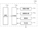
また、本実施形態では、通信端末11Aが、CPU11aと、このCPU11aによって実行されるプログラムを記憶する補助記憶部11cを含んで構成されている。これに限らず、通信端末11Aは、例えば図11に示されるように、通信ユニット11d、記憶部11e、距離計測部11f、距離算出部11g、演算部11h、及び特定部11iを含んで構成されていてもよい。
In the present embodiment, the
この変形例に係る通信端末11Aでは、記憶部11eは、通信ユニット11dの通信結果、及び上記各部11f〜11iでの処理結果を記憶する。また、距離計測部11fは、計測距離MD(i)を算出する。また、距離算出部11gは、計算距離CD(i)を算出する。また、演算部11hは、判定値ETMを算出する。また、特定部11iは、判定値ETMに基づいて、通信端末11Aのスペース30における位置を特定する。そして、この特定結果を外部機器等へ出力する。
In the
また、本実施形態では、電磁波の到達時間に基づいて、通信端末11Aと基準端末211〜214との間の距離を計測した。これに限らず、電磁波の減衰量に基づいて、通信端末11Aと基準端末211〜214との間の距離を計測してもよい。一般に、搬送波は距離の2乗に比例して減衰する。このため、通信端末11Aは、基準端末211〜214から出力されたときの電磁波の強度と、受信した電磁波の強度との差から、通信端末11Aと基準端末211〜214との間の距離を計測することができる。
In the present embodiment, the distance between the
この場合、電波を受信する地点での電界強度は、反射波の干渉によるマルチパスフェージングによる誤差を含んでいる。さらに、電界強度は距離の2乗に比例して弱くなる。このため、例えば、ある一定の距離に対して電界強度の対数が正規分布となるようなばらつきを持つと仮定すると、計測距離MD(i)の誤差の確率密度分布は図12に示されるグラフのようになる。このように、電磁波の減衰量に基づいて距離を計測する方法によっても、計測距離の誤差は正規分布とはならない。したがって、実環境において、通信端末11Aと基準端末211〜214との間の計測距離MD(i)のうちのいずれかが、マルチパスの影響を受けることにより、実際の距離よりも大きくなることが考えられる。
In this case, the electric field strength at the point where the radio wave is received includes an error due to multipath fading due to interference of reflected waves. Furthermore, the electric field strength becomes weaker in proportion to the square of the distance. For this reason, for example, assuming that the logarithm of the electric field strength has a normal distribution with respect to a certain distance, the probability density distribution of the error of the measurement distance MD (i) is as shown in the graph shown in FIG. It becomes like this. Thus, the error of the measurement distance does not become a normal distribution even by the method of measuring the distance based on the attenuation amount of the electromagnetic wave. Therefore, in the actual environment, any one of the measured distances MD (i) between the
本発明は、電磁波の減衰を用いて距離の計測を行う場合にも、通信端末11Aのスペース30における位置を、マルチパスの影響を受けることなく、精度よく特定することができる。
The present invention can accurately identify the position of the
《第2の実施形態》
次に本発明の第2の実施形態について、図面を参照しつつ説明する。なお、第1の実施形態と同一又は同等の構成については、同等の符号を用いるとともに、その説明を省略又は簡略する。
<< Second Embodiment >>
Next, a second embodiment of the present invention will be described with reference to the drawings. In addition, about the structure same or equivalent to 1st Embodiment, while using an equivalent code | symbol, the description is abbreviate | omitted or simplified.
図13は、本実施形態に係る測位システム10の概略的な構成を示す図である。測位システム10は、複数の通信端末相互間の距離の計測を行い、それぞれの通信端末に対する、他の通信端末の相対位置を特定するシステムである。この測位システム10は、管理端末22と、5つの通信端末11A〜11Eとから構成されている。
FIG. 13 is a diagram illustrating a schematic configuration of the
通信端末11A〜11Eそれぞれは、他の通信端末との間で無線通信を行うとともに、管理端末22との間で無線通信を行う。また、通信端末11A〜11Eそれぞれは、直接通信ができない通信端末に対して、通信可能な他の通信端末を仲介して通信を行う、いわゆるマルチポップ通信を行うことができる。例えば、図13を参照するとわかるように、通信端末11Aは、通信端末11Eと直接的に無線通信を行うことはできないが、通信端末11B或いは通信端末11Cを介して、間接的に通信端末11Eと無線通信を行うことができる。以下、説明の便宜上、直接無線通信を行うことが可能な通信端末を隣接端末ともいうものとする。例えば、通信端末11Aと直接無線通信を行うことが可能な通信端末11B,11Cを、通信端末11Aの隣接端末11B,11Cとも表示する。
Each of the communication terminals 11 </ b> A to 11 </ b> E performs wireless communication with other communication terminals and wireless communication with the
図14は、管理端末22のブロック図である。図14に示されるように、管理端末22は、CPU22a、主記憶部22b、補助記憶部22c、及び通信ユニット22dを有している。
FIG. 14 is a block diagram of the
この管理端末22の補助記憶部22cは、CPU22aが実行するプログラムと、各通信端末11A〜11Eの識別ID(A)〜ID(E)などを記憶している。また、補助記憶部22cは、各通信端末11A〜11Eから送信される情報を逐次記憶する。
The
本測位システム10では、通信端末11A〜11Eから管理端末22へ計測結果が送信され、管理端末22によって、各通信端末11A〜11Eの相対位置が測位される。以下、管理端末22の動作について、図15のフローチャートに基づいて説明する。
In the
まず、管理端末22のCPU22aは、各通信端末11A〜11Eに、測位指令を送信する(ステップS301)。これにより、通信端末11A〜11Eそれぞれは、第1の実施形態で説明した手順で、隣接端末との距離を計測する。そして、通信端末11A〜11Eそれぞれは、計測して得た計測距離を、管理端末22へ送信する。
First, the
次に、CPU22aは、通信端末11A〜11Eのなかから、相互に通信可能な3つの通信端末を基準端末として選択する(ステップS302)。例えば、ここでは3つの通信端末11A,11B,11Cを選択する。
Next, the
次に、CPU22aは、選択した通信端末の基準位置を特定する。例えば、CPU22aは、通信端末11Aの位置を原点(0,0)とし、通信端末11Bの位置を(XB、0)とし、通信端末11Cの位置を(XC,YC)と定義する。これは、一例として、図16に示されるように、通信端末11Aの位置を原点とし、この原点と通信端末11Bの位置を通るx軸と、原点を通りx軸に直交するy軸とから規定されるxy座標系を定義するのと等価である。そして、CPU22aは、通信端末11Aと通信端末11Bとの計測距離MD(AB)から、xy座標系における通信端末11Bの位置(XB,0)を特定する。そして、通信端末11Aと通信端末11Cとの計測距離MD(AC)と、通信端末11Bと通信端末11Cとの計測距離MD(BC)とから、xy座標系における通信端末11Cの位置(XC,YC)を特定する。これにより、通信端末11A,11B,11Cが位置するところが基準位置となる(ステップS303)。
Next, the
次に、CPU22aは、xy座標系における位置が特定された3つ以上の通信端末を隣接端末として有する通信端末を選択する(ステップS304)。ここでは、位置が特定された通信端末11A,11B,11Cを隣接端末として有する通信端末11Dが選択される。
Next, the
次に、管理端末22は、基準端末に対する隣接端末の位置を特定する。例えば、管理端末22は、この隣接端末11Dと通信端末11A〜11Cとの計測距離MD(DA),MD(DB),MD(DC)を用いて、隣接端末11Dの、通信端末11A〜11Cを基準とする位置を特定する(ステップS305)。これにより、通信端末11Dのxy座標系における位置が特定される。
Next, the
この位置を特定する過程では、第1の実施形態で説明した式(3)で表される演算と同等の演算が行われる。これにより、x軸に平行なグリッド線と、y軸に平行なグリッド線とによって規定される点PMと通信端末11A〜11Cとの計算距離CDM(A)〜CDM(C)と、計測距離MD(DA),MD(DB),MD(DC)との関係が評価関数によって評価され、マルチパスによる誤差を含むと考えられる計測距離が除外された上で、通信端末11Dの位置が特定される。
In the process of specifying this position, an operation equivalent to the operation represented by Expression (3) described in the first embodiment is performed. Thereby, the calculation distances CD M (A) to CD M (C) between the point P M defined by the grid line parallel to the x axis and the grid line parallel to the y axis and the
次に、CPU22aは、測位システム10を構成する通信端末11A〜11Eのうちから、位置が特定されていない通信端末の有無を確認する(ステップS306)。ここでの判断が肯定された場合(ステップS306:Yes)には、CPU22aは、ステップS304〜ステップS306までの処理を繰り返し実行する。これにより、通信端末11Eについて、基準端末としての隣接端末11B〜11Dとの計測距離MD(EB),MD(EC),MD(ED)に基づく位置の特定が行われる。一方、ここでの判断が否定された場合には(ステップS306:No)、管理端末22は、処理を終了する。
Next, CPU22a confirms the presence or absence of the communication terminal from which the position is not specified among
以上説明したように、本実施形態では、マルチパスによる誤差を含むと考えられる計測距離MDが、評価関数Eを用いた演算が行われる過程で除外される。そして、マルチパスによる誤差を含まない計測距離MDに基づいて、通信端末11A〜11Eそれぞれのxy座標系における位置が精度良く特定される。
As described above, in the present embodiment, the measurement distance MD that is considered to include an error due to multipath is excluded in the process in which the calculation using the evaluation function E is performed. And the position in each xy coordinate system of each of
また、本実施形態では、管理端末22は、定期的に図15に示される処理を実行することで、スペース30を移動するユーザ51相互間の位置関係をリアルタイムに検出することが可能となる。
Further, in the present embodiment, the
また、本実施形態では、最初に3つの通信端末11A〜11Cの位置が特定された後、順次残りの通信端末11D,11Eの位置が特定される。このため、直接無線通信ができない通信端末間の相対位置を精度よく特定することができる。
Further, in the present embodiment, after the positions of the three
なお、本実施形態では、管理端末22は、通信端末11A〜11Eのなかから、相互に通信可能な3つの通信端末11A〜11Cを基準端末として選択し、この基準端末11A〜11Cのxy座標系における位置を特定した。これに限らず、通信端末11A〜11Cのスペース30における位置がわかっている場合には、この位置情報を用いて、他の通信端末11D,11Eの位置を特定してもよい。この方法によれば、通信端末11D,11Eのスペース30における絶対位置を特定することができる。
In the present embodiment, the
また、本実施形態では、通信端末11A〜11Eが、一例としてユーザ51によって所持されている場合について説明した。通信端末11A〜11Eは、必ずしもユーザ51に所持されている必要はなく、例えば、通信端末11A〜11Eは、空調装置等のリモコンとして、室内空間で利用されるものであってもよい。また、通信端末11A〜11Eは、室内空間に配置される機器に設けられていてもよい。この場合には、室内空間に複数の機器を設置した際に、室内空間における各機器の配置を容易に把握することができる。このため、機器の配置に応じて、それぞれの機器の制御を行うことが可能となる。
Moreover, in this embodiment, the case where the
また、本実施形態では、管理端末22が、CPU11aと、このCPU11aによって実行されるプログラムを記憶する補助記憶部11cを含んで構成されている。これに限らず、管理端末22は、例えば図17に示されるように、通信ユニット22d、記憶部22e、選択部22f、距離計測部22g、距離算出部22h、演算部22i、及び特定部22jを含んで構成されていてもよい。
In the present embodiment, the
この変形例に係る管理端末22では、記憶部22eは、通信ユニット22dの通信結果、及び上記各部22f〜22jでの処理結果を記憶する。また、選択部22fは、通信端末11A〜11Eのなかから、相互に通信可能な3つの通信端末を基準端末として選択する。そして、この基準端末の位置を基準位置に設定する。また、距離計測部22gは、隣接端末と基準端末との間の計測距離MDを算出する。また、距離算出部22hは、計算距離CDMを算出する。また、演算部22iは、判定値ETMを算出する。また、特定部22jは、判定値ETMに基づいて、xy座標系における隣接端末11D,11Eの位置を特定する。そして、この特定結果を外部機器等へ出力する。
In the
以上、本発明の実施形態について説明したが、本発明は、本発明の広義の精神と範囲を逸脱することなく、様々な実施形態及び変形が可能とされるものである。また、上述した実施形態は、本発明を説明するためのものであり、本発明の範囲を限定するものではない。つまり、本発明の範囲は、実施形態ではなく、特許請求の範囲によって示される。 Although the embodiments of the present invention have been described above, various embodiments and modifications can be made without departing from the broad spirit and scope of the present invention. Further, the above-described embodiment is for explaining the present invention, and does not limit the scope of the present invention. That is, the scope of the present invention is shown not by the embodiments but by the claims.
本発明の位置特定方法、測位システム及びプログラムは、通信端末の位置を特定するのに適している。 The position specifying method, positioning system, and program of the present invention are suitable for specifying the position of a communication terminal.
10 測位システム
11A〜11E 通信端末
11a CPU
11b 主記憶部
11c 補助記憶部
11d 通信ユニット
11e 記憶部
11f 距離計測部
11g 距離算出部
11h 演算部
11i 特定部
211〜214 基準端末
21a CPU
21b 主記憶部
21c 補助記憶部
21d 通信ユニット
22 管理端末
22a CPU
22b 主記憶部
22c 補助記憶部
22d 通信ユニット
22e 記憶部
22f 選択部
22g 距離計測部
22h 距離算出部
22i 演算部
22j 特定部
30 スペース
51 ユーザ
10
11b
21b
22b
Claims (12)
前記基準位置にそれぞれ配置された基準端末と、前記通信端末との通信結果に基づいて、前記通信端末と前記基準端末との間の第1距離を計測する工程と、
前記通信端末の、前記所定の範囲における仮定の位置を順次決定する工程と、
前記基準端末と前記仮定の位置との間の第2距離を順次算出する工程と、
前記第1距離と前記第2距離との差が、所定の閾値よりも大きい場合に、ほぼ零となる値を出力し、それ以外の場合に、前記差に応じた値を出力する評価関数を用いた演算を行う工程と、
前記演算により、前記基準端末毎に算出された前記値の合計が最も大きいときの、前記仮定の位置を前記通信端末の位置として特定する工程と、
を含む位置特定方法。 A position specifying method for specifying a position of the communication terminal based on a distance between a communication terminal existing in a predetermined range and a plurality of reference positions,
A step of measuring a first distance between the communication terminal and the reference terminal based on a communication result between the reference terminal and the communication terminal respectively arranged at the reference position;
Sequentially determining a hypothetical position of the communication terminal in the predetermined range;
Sequentially calculating a second distance between the reference terminal and the assumed position;
An evaluation function that outputs a value that is substantially zero when the difference between the first distance and the second distance is greater than a predetermined threshold, and outputs a value corresponding to the difference in the other cases. A process of performing the operation used;
The step of specifying the assumed position as the position of the communication terminal when the sum of the values calculated for each reference terminal is the largest by the calculation;
Location method including
前記基準端末が位置するところを前記基準位置に設定する工程と、
を更に含む請求項1に記載の位置特定方法。 Selecting the communication terminal to be the reference terminal from a plurality of the communication terminals;
Setting the reference position where the reference terminal is located;
The position specifying method according to claim 1, further comprising:
所定の範囲に存在し、前記基準端末と無線通信を行う通信端末と、
前記基準端末と、前記通信端末との通信結果に基づいて、前記通信端末と前記基準端末との間の第1距離を計測する距離計測手段と、
前記通信端末の、前記所定の範囲における仮定の位置を順次決定し、前記基準端末と前記仮定の位置との間の第2距離を順次算出する距離算出手段と、
前記第1距離と前記第2距離との差が、所定の閾値よりも大きい場合に、ほぼ零となる値を出力し、それ以外の場合に、前記差に応じた値を出力する評価関数を用いた演算を行う演算手段と、
前記演算により、前記基準端末毎に算出された前記値の合計が最も大きいときの、前記仮定の位置を前記通信端末の位置として特定する位置特定手段と、
を備える測位システム。 A reference terminal arranged at a reference position;
A communication terminal that exists in a predetermined range and performs wireless communication with the reference terminal;
Distance measuring means for measuring a first distance between the communication terminal and the reference terminal based on a communication result between the reference terminal and the communication terminal;
Distance calculation means for sequentially determining a hypothetical position of the communication terminal in the predetermined range and sequentially calculating a second distance between the reference terminal and the hypothetical position;
An evaluation function that outputs a value that is substantially zero when the difference between the first distance and the second distance is greater than a predetermined threshold, and outputs a value corresponding to the difference in the other cases. A calculation means for performing the calculation used;
A position specifying means for specifying the assumed position as the position of the communication terminal when the sum of the values calculated for each reference terminal is the largest by the calculation;
Positioning system with
複数の前記通信端末のなかから、複数の前記通信端末の相対位置を特定するための基準となる前記通信端末を、基準端末として選択する選択手段と、
前記基準端末と、前記基準端末以外の前記通信端末との通信結果に基づいて、前記基準端末と、前記基準端末以外の前記通信端末との間の第1距離を計測する距離計測手段と、
前記基準端末以外の前記通信端末の、前記所定の範囲における仮定の位置を順次決定し、前記基準端末と前記仮定の位置との間の第2距離を順次算出する距離算出手段と、
前記第1距離と前記第2距離との差が、所定の閾値よりも大きい場合に、ほぼ零となる値を出力し、それ以外の場合に、前記差に応じた値を出力する評価関数を用いた演算を行う演算手段と、
前記演算により、前記基準端末毎に算出された前記値の合計が最も大きいときの、前記仮定の位置を前記通信端末の位置として特定する位置特定手段と、
を備える測位システム。 A plurality of communication terminals that exist within a predetermined range and communicate with each other;
Selecting means for selecting, as a reference terminal, the communication terminal serving as a reference for specifying the relative position of the plurality of communication terminals from among the plurality of communication terminals;
Distance measuring means for measuring a first distance between the reference terminal and the communication terminal other than the reference terminal based on a communication result between the reference terminal and the communication terminal other than the reference terminal;
Distance calculating means for sequentially determining assumed positions in the predetermined range of the communication terminals other than the reference terminal, and sequentially calculating a second distance between the reference terminal and the assumed position;
An evaluation function that outputs a value that is substantially zero when the difference between the first distance and the second distance is greater than a predetermined threshold, and outputs a value corresponding to the difference in the other cases. A calculation means for performing the calculation used;
A position specifying means for specifying the assumed position as the position of the communication terminal when the sum of the values calculated for each reference terminal is the largest by the calculation;
Positioning system with
基準位置にそれぞれ配置された基準端末と、通信端末との通信結果に基づいて、前記通信端末と前記基準端末との間の第1距離を算出する手順と、
前記通信端末の、前記所定の範囲における仮定の位置を順次決定する手順と、
前記基準端末の位置と、前記仮定の位置との間の第2距離を順次算出する手順と、
前記第1距離と前記第2距離との差が、所定の閾値よりも大きい場合に、ほぼ零となる値を出力し、それ以外の場合に、前記差に応じた値を出力する評価関数を用いた演算を行う手順と、
前記演算により、前記基準端末毎に算出された前記値の合計が最も大きいときの、前記仮定の位置を前記通信端末の位置として特定する手順と、
を実行させるためのプログラム。 On the computer,
A procedure for calculating a first distance between the communication terminal and the reference terminal based on a communication result between the reference terminal and the communication terminal respectively arranged at the reference position;
A procedure for sequentially determining a hypothetical position of the communication terminal in the predetermined range;
A step of sequentially calculating a second distance between the position of the reference terminal and the assumed position;
An evaluation function that outputs a value that is substantially zero when the difference between the first distance and the second distance is greater than a predetermined threshold, and outputs a value corresponding to the difference in the other cases. The procedure for performing the calculations used;
A procedure for specifying the assumed position as the position of the communication terminal when the sum of the values calculated for each reference terminal is the largest by the calculation;
A program for running
Priority Applications (1)
| Application Number | Priority Date | Filing Date | Title |
|---|---|---|---|
| JP2009255046A JP5116750B2 (en) | 2009-11-06 | 2009-11-06 | LOCATION METHOD, POSITIONING SYSTEM, AND PROGRAM |
Applications Claiming Priority (1)
| Application Number | Priority Date | Filing Date | Title |
|---|---|---|---|
| JP2009255046A JP5116750B2 (en) | 2009-11-06 | 2009-11-06 | LOCATION METHOD, POSITIONING SYSTEM, AND PROGRAM |
Publications (2)
| Publication Number | Publication Date |
|---|---|
| JP2011099778A JP2011099778A (en) | 2011-05-19 |
| JP5116750B2 true JP5116750B2 (en) | 2013-01-09 |
Family
ID=44191065
Family Applications (1)
| Application Number | Title | Priority Date | Filing Date |
|---|---|---|---|
| JP2009255046A Active JP5116750B2 (en) | 2009-11-06 | 2009-11-06 | LOCATION METHOD, POSITIONING SYSTEM, AND PROGRAM |
Country Status (1)
| Country | Link |
|---|---|
| JP (1) | JP5116750B2 (en) |
Families Citing this family (11)
| Publication number | Priority date | Publication date | Assignee | Title |
|---|---|---|---|---|
| EP2505307B1 (en) | 2011-03-31 | 2014-01-08 | Makita Corporation | Power tool |
| JP2013110606A (en) * | 2011-11-21 | 2013-06-06 | Fujitsu Ltd | Terminal device, location identification method and program |
| JP6064347B2 (en) * | 2012-03-22 | 2017-01-25 | カシオ計算機株式会社 | Information processing apparatus and program |
| CN103379427B (en) | 2012-04-13 | 2016-06-15 | 华为技术有限公司 | A kind of localization method, equipment and system |
| JP2014215134A (en) * | 2013-04-24 | 2014-11-17 | 株式会社東芝 | Position estimation device, position estimation method, and radio communication system |
| JP6177612B2 (en) * | 2013-07-26 | 2017-08-09 | 株式会社田定工作所 | Positioning method and positioning device using signals from aircraft |
| JP6311505B2 (en) * | 2014-07-09 | 2018-04-18 | 株式会社デンソー | Positioning device |
| JP6703094B2 (en) * | 2016-03-16 | 2020-06-03 | アルプスアルパイン株式会社 | Position detection system |
| GB2551347B (en) * | 2016-06-13 | 2020-04-15 | Toshiba Kk | Indoor localisation using received signal quality weights |
| JP7036755B2 (en) * | 2019-01-28 | 2022-03-15 | 大井電気株式会社 | Positioning device |
| CN113474671A (en) * | 2019-02-24 | 2021-10-01 | 洛希克斯有限公司 | System and method for precise radio frequency location using time difference of arrival for time scanning |
Family Cites Families (4)
| Publication number | Priority date | Publication date | Assignee | Title |
|---|---|---|---|---|
| JP3461167B2 (en) * | 2001-02-07 | 2003-10-27 | 株式会社日立製作所 | Position calculation method and position calculation device |
| JP5075396B2 (en) * | 2006-11-09 | 2012-11-21 | アズビル株式会社 | Position estimation method and position estimation system |
| JP2008249396A (en) * | 2007-03-29 | 2008-10-16 | Brother Ind Ltd | Position detecting system utilizing quiescence determination by mobile station |
| JP2009069026A (en) * | 2007-09-13 | 2009-04-02 | Brother Ind Ltd | Mobile station positioning system |
-
2009
- 2009-11-06 JP JP2009255046A patent/JP5116750B2/en active Active
Also Published As
| Publication number | Publication date |
|---|---|
| JP2011099778A (en) | 2011-05-19 |
Similar Documents
| Publication | Publication Date | Title |
|---|---|---|
| JP5116750B2 (en) | LOCATION METHOD, POSITIONING SYSTEM, AND PROGRAM | |
| CN109963287B (en) | Antenna direction angle optimization method, device, equipment and medium | |
| US9883407B2 (en) | Radio wave propagation environment measuring apparatus, radio network construction system, and method for measuring radio wave propagation environment | |
| JP5818779B2 (en) | Position detection system using fingerprint method and position detection method | |
| EP3404439A1 (en) | Cluster-based magnetic positioning method, device and system | |
| CN101923118B (en) | Building influence estimation apparatus and building influence estimation method | |
| JP5075396B2 (en) | Position estimation method and position estimation system | |
| JP2008233066A (en) | Positioning system, positioning method and positioning program | |
| JP2018519506A (en) | Device and method for tracking | |
| TWI544822B (en) | Signal strength distribution establishing method and wireless positioning system | |
| KR101709411B1 (en) | Method for positioning based on weighted triangulation and method for indoor positioning using the same | |
| RU2573592C2 (en) | Method and node for localising node in wireless network | |
| JP5358386B2 (en) | Indoor environment control system and method | |
| JP2006090868A (en) | Position determination method, apparatus, and system | |
| JP2011099809A (en) | Radio positioning system, radio positioning method, and program | |
| CN102573055B (en) | Method for locating nodes in wireless sensor network | |
| US20200209345A1 (en) | Method and apparatus for location estimation of terminal in wireless communication system | |
| WO2021186941A1 (en) | Position estimation device, position estimation method, and position estimation program | |
| US20180279078A1 (en) | Confirming work supporting device, confirming work supporting system, and computer program product | |
| Vaščák et al. | Radio beacons in indoor navigation | |
| CN109587631B (en) | Indoor positioning method and device | |
| CN103796303A (en) | Terminal positioning method, related device and terminal positioning system | |
| US20210329478A1 (en) | Radio wave strength estimation device, position estimation system, and radio wave strength estimation method | |
| Wattananavin et al. | REDUCTION OF RSSI VARIATION AND POSITION ESTIMATION ERROR CAUSED BY HUMAN MOVEMENTS IN AN RSSI-BASED INDOOR LOCALIZATION SYSTEM. | |
| JP2021047115A (en) | Location measurement system |
Legal Events
| Date | Code | Title | Description |
|---|---|---|---|
| A977 | Report on retrieval |
Free format text: JAPANESE INTERMEDIATE CODE: A971007 Effective date: 20110921 |
|
| A131 | Notification of reasons for refusal |
Free format text: JAPANESE INTERMEDIATE CODE: A131 Effective date: 20110927 |
|
| TRDD | Decision of grant or rejection written | ||
| A01 | Written decision to grant a patent or to grant a registration (utility model) |
Free format text: JAPANESE INTERMEDIATE CODE: A01 Effective date: 20120918 |
|
| A01 | Written decision to grant a patent or to grant a registration (utility model) |
Free format text: JAPANESE INTERMEDIATE CODE: A01 |
|
| A61 | First payment of annual fees (during grant procedure) |
Free format text: JAPANESE INTERMEDIATE CODE: A61 Effective date: 20121016 |
|
| R150 | Certificate of patent or registration of utility model |
Ref document number: 5116750 Country of ref document: JP Free format text: JAPANESE INTERMEDIATE CODE: R150 Free format text: JAPANESE INTERMEDIATE CODE: R150 |
|
| FPAY | Renewal fee payment (event date is renewal date of database) |
Free format text: PAYMENT UNTIL: 20151026 Year of fee payment: 3 |
|
| R250 | Receipt of annual fees |
Free format text: JAPANESE INTERMEDIATE CODE: R250 |
|
| R250 | Receipt of annual fees |
Free format text: JAPANESE INTERMEDIATE CODE: R250 |
|
| R250 | Receipt of annual fees |
Free format text: JAPANESE INTERMEDIATE CODE: R250 |
|
| R250 | Receipt of annual fees |
Free format text: JAPANESE INTERMEDIATE CODE: R250 |
|
| R250 | Receipt of annual fees |
Free format text: JAPANESE INTERMEDIATE CODE: R250 |
|
| R250 | Receipt of annual fees |
Free format text: JAPANESE INTERMEDIATE CODE: R250 |
|
| R250 | Receipt of annual fees |
Free format text: JAPANESE INTERMEDIATE CODE: R250 |
|
| R250 | Receipt of annual fees |
Free format text: JAPANESE INTERMEDIATE CODE: R250 |
|
| R250 | Receipt of annual fees |
Free format text: JAPANESE INTERMEDIATE CODE: R250 |