JP5116633B2 - Central venous catheter - Google Patents
Central venous catheter Download PDFInfo
- Publication number
- JP5116633B2 JP5116633B2 JP2008279870A JP2008279870A JP5116633B2 JP 5116633 B2 JP5116633 B2 JP 5116633B2 JP 2008279870 A JP2008279870 A JP 2008279870A JP 2008279870 A JP2008279870 A JP 2008279870A JP 5116633 B2 JP5116633 B2 JP 5116633B2
- Authority
- JP
- Japan
- Prior art keywords
- heat exchange
- central venous
- catheter
- patient
- venous line
- Prior art date
- Legal status (The legal status is an assumption and is not a legal conclusion. Google has not performed a legal analysis and makes no representation as to the accuracy of the status listed.)
- Expired - Fee Related
Links
Images


Classifications
-
- A—HUMAN NECESSITIES
- A61—MEDICAL OR VETERINARY SCIENCE; HYGIENE
- A61F—FILTERS IMPLANTABLE INTO BLOOD VESSELS; PROSTHESES; DEVICES PROVIDING PATENCY TO, OR PREVENTING COLLAPSING OF, TUBULAR STRUCTURES OF THE BODY, e.g. STENTS; ORTHOPAEDIC, NURSING OR CONTRACEPTIVE DEVICES; FOMENTATION; TREATMENT OR PROTECTION OF EYES OR EARS; BANDAGES, DRESSINGS OR ABSORBENT PADS; FIRST-AID KITS
- A61F7/00—Heating or cooling appliances for medical or therapeutic treatment of the human body
- A61F7/12—Devices for heating or cooling internal body cavities
- A61F7/123—Devices for heating or cooling internal body cavities using a flexible balloon containing the thermal element
-
- A—HUMAN NECESSITIES
- A61—MEDICAL OR VETERINARY SCIENCE; HYGIENE
- A61M—DEVICES FOR INTRODUCING MEDIA INTO, OR ONTO, THE BODY; DEVICES FOR TRANSDUCING BODY MEDIA OR FOR TAKING MEDIA FROM THE BODY; DEVICES FOR PRODUCING OR ENDING SLEEP OR STUPOR
- A61M1/00—Suction or pumping devices for medical purposes; Devices for carrying-off, for treatment of, or for carrying-over, body-liquids; Drainage systems
- A61M1/36—Other treatment of blood in a by-pass of the natural circulatory system, e.g. temperature adaptation, irradiation ; Extra-corporeal blood circuits
- A61M1/3621—Extra-corporeal blood circuits
- A61M1/3623—Means for actively controlling temperature of blood
-
- A—HUMAN NECESSITIES
- A61—MEDICAL OR VETERINARY SCIENCE; HYGIENE
- A61B—DIAGNOSIS; SURGERY; IDENTIFICATION
- A61B18/00—Surgical instruments, devices or methods for transferring non-mechanical forms of energy to or from the body
- A61B2018/00005—Cooling or heating of the probe or tissue immediately surrounding the probe
- A61B2018/00011—Cooling or heating of the probe or tissue immediately surrounding the probe with fluids
-
- A—HUMAN NECESSITIES
- A61—MEDICAL OR VETERINARY SCIENCE; HYGIENE
- A61M—DEVICES FOR INTRODUCING MEDIA INTO, OR ONTO, THE BODY; DEVICES FOR TRANSDUCING BODY MEDIA OR FOR TAKING MEDIA FROM THE BODY; DEVICES FOR PRODUCING OR ENDING SLEEP OR STUPOR
- A61M1/00—Suction or pumping devices for medical purposes; Devices for carrying-off, for treatment of, or for carrying-over, body-liquids; Drainage systems
- A61M1/36—Other treatment of blood in a by-pass of the natural circulatory system, e.g. temperature adaptation, irradiation ; Extra-corporeal blood circuits
- A61M1/369—Temperature treatment
-
- A—HUMAN NECESSITIES
- A61—MEDICAL OR VETERINARY SCIENCE; HYGIENE
- A61M—DEVICES FOR INTRODUCING MEDIA INTO, OR ONTO, THE BODY; DEVICES FOR TRANSDUCING BODY MEDIA OR FOR TAKING MEDIA FROM THE BODY; DEVICES FOR PRODUCING OR ENDING SLEEP OR STUPOR
- A61M5/00—Devices for bringing media into the body in a subcutaneous, intra-vascular or intramuscular way; Accessories therefor, e.g. filling or cleaning devices, arm-rests
- A61M5/44—Devices for bringing media into the body in a subcutaneous, intra-vascular or intramuscular way; Accessories therefor, e.g. filling or cleaning devices, arm-rests having means for cooling or heating the devices or media
Landscapes
- Health & Medical Sciences (AREA)
- Heart & Thoracic Surgery (AREA)
- Vascular Medicine (AREA)
- Animal Behavior & Ethology (AREA)
- Public Health (AREA)
- Engineering & Computer Science (AREA)
- Veterinary Medicine (AREA)
- Life Sciences & Earth Sciences (AREA)
- Biomedical Technology (AREA)
- General Health & Medical Sciences (AREA)
- Physics & Mathematics (AREA)
- Thermal Sciences (AREA)
- Cardiology (AREA)
- Anesthesiology (AREA)
- Hematology (AREA)
- Thermotherapy And Cooling Therapy Devices (AREA)
- Media Introduction/Drainage Providing Device (AREA)
- External Artificial Organs (AREA)
- Infusion, Injection, And Reservoir Apparatuses (AREA)
Abstract
Description
本発明は、患者の中心静脈血液供給部へアクセスするために使用される中心静脈線カテーテルに関する。 The present invention relates to a central venous line catheter used to access a patient's central venous blood supply.
中心静脈線カテーテル等のカテーテルは、典型的にはICU(集中治療室)患者、特には卒中または他の脳の外傷性イベントを被った患者に対して使用される。それらの中心静脈線カテーテルは、典型的には、サイズが約8.5〜12Frenchであり、8〜12インチにわたって延在する軟質で可撓性の多内腔構造体からなっている。それらのカテーテルは、通常、医療担当者が中心静脈系を介して患者の中心血液供給部へ容易且つ便利にアクセスできるように、患者の鎖骨下静脈または頸静脈を通じて導入され、また、好適性が幾分劣るものの、大腿静脈も利用される。一般的に、このようにして中心血液供給部へのアクセスが達成され、これにより、血液ガス分析等のために患者の血液を収集することが可能になると共に、例えば、薬剤や、注入液、または栄養剤の送給が可能になる。 Catheters, such as central venous catheters, are typically used for ICU (intensive care unit) patients, particularly those suffering from stroke or other brain traumatic events. These central venous catheters are typically about 8.5-12 French in size and consist of a soft, flexible multi-lumen structure extending over 8-12 inches. These catheters are usually introduced through the patient's subclavian or jugular veins and are suitable for medical personnel to easily and conveniently access the patient's central blood supply via the central venous system. Although somewhat inferior, the femoral vein is also used. In general, access to the central blood supply is thus achieved, which allows the patient's blood to be collected for blood gas analysis and the like, for example, drugs, infusions, Or feeding of nutrients becomes possible.
ICU患者等の多くの患者で発熱が生じることは珍しくない。特に神経系ICU患者で発熱が生じやすく、その発現は、脳における有害な影響を悪化させることがある。発熱を管理するための通常の治療法は、アセトアミノフェン(Tylenol)や、冷却毛布、氷水膀胱灌注及び氷浴を用いる治療法を含む。患者の体温を下げるためのこれらの手法はすべて、患者を冷やすのに過剰な時間を必要とする。しかも、それらの従来の方法は、患者の冷却状態を正確に制御することができない。ここで認識されるように、患者を冷却することによる有益性を最適化するためには、制御された仕方で比較的迅速に患者を冷やすことが重要である。 It is not uncommon for many patients, such as ICU patients, to develop fever. Fever is likely to occur, especially in nervous system ICU patients, and its expression can exacerbate harmful effects in the brain. Conventional therapies for managing fever include acetaminophen (Tylenol), treatments using cooling blankets, ice water bladder irrigation and ice baths. All of these approaches to lowering the patient's temperature require excessive time to cool the patient. Moreover, these conventional methods cannot accurately control the patient's cooling state. As will be appreciated, in order to optimize the benefits of cooling the patient, it is important to cool the patient relatively quickly in a controlled manner.
ICU患者における発熱による上述の有害な影響と、現在の温度調節方法及び装置の不十分性を認識し、本譲受人は、同時係属特許出願第09/133,813号及び第09/063,984号において、患者の血液供給部から熱を取り除くために患者の体内に移植することができる留置カテーテルを開示した。それらの上記引用出願公報の留置カテーテルは、血液供給部と熱交換関係をもたらすように配置され、そして、そのカテーテルを通じて、冷却剤が閉鎖ループ内で循環される。これらのカテーテルは、生体組織の温度を下げ、これにより、上述の如く、患者の医療上の成果を改善することができる。 Recognizing the aforementioned detrimental effects of fever in ICU patients and the insufficiency of current temperature control methods and devices, the assignee is assigned to co-pending patent applications 09 / 133,813 and 09 / 063,984. Disclosed an indwelling catheter that can be implanted into a patient's body to remove heat from the patient's blood supply. The indwelling catheters of those cited applications are arranged to provide a heat exchange relationship with the blood supply and through which the coolant is circulated in a closed loop. These catheters can lower the temperature of the living tissue, thereby improving the patient's medical outcome, as described above.
本発明により理解されるように、上で引用された冷却用カテーテルの利点は、中心静脈カテーテルの形態に組込まれる。上述の如く、中心静脈カテーテルは、通常、神経系ICU患者を含む多くのICU患者で使用されることから、本発明者らは、これらの認識を組み合わせて、患者を冷却するという付加的な能力を備えた中心静脈カテーテルを提供できれば有利であろうと考えた。これを成し遂げるため、本発明は、単一の装置で、従来の中心静脈カテーテルと、患者の体温を効果的且つ正確に管理するための手段を提供することという2つの目標を達成する。 As will be understood by the present invention, the advantages of the cooling catheter cited above are incorporated into the form of a central venous catheter. As noted above, since central venous catheters are typically used in many ICU patients, including nervous system ICU patients, we have the added ability to combine these perceptions to cool the patient. It would be advantageous to be able to provide a central venous catheter with To accomplish this, the present invention achieves the two goals of providing a central central venous catheter and a means for effectively and accurately managing patient temperature in a single device.
本発明は、患者の身体と能動的に熱交換し、これにより必要に応じて体温を上昇もしくは低下させることができるようになされた中心静脈線カテーテルを提供することにより、従来技術の不十分さを克服する。中心静脈線には、患者の血液と熱交換関係を持って配置される熱交換エレメントが供給される。この熱交換エレメントは、循環する流体をその内部に収容しており、そして、この流体は、患者体温フィードバック機構に従って、患者の身体の外部で自動的に冷却または加温される。 The present invention lacks the prior art by providing a central venous catheter that is capable of actively exchanging heat with the patient's body, thereby increasing or decreasing body temperature as needed. Overcome. The central venous line is supplied with a heat exchange element that is placed in heat exchange relationship with the patient's blood. The heat exchange element contains a circulating fluid therein and the fluid is automatically cooled or warmed outside the patient's body according to a patient temperature feedback mechanism.
中心静脈線カテーテルの既知の機能に患者の血液を冷却または加温する機能を追加することにより、本発明は、その静脈系への現存するアクセス及び単一の切開部を利用でき、これにより、付加的な合併症の危険性が低減されるという長所を有している。典型的には鎖骨下静脈や、頸静脈あるいは大腿静脈を通じて行われるこのアクセスは、その中心静脈系を介して中心血液供給部へなされ、従って、患者の体温を効果的に冷却または加温できるため、特に好都合である。中心静脈系という用語は、一般的に、下大静脈及び上大静脈を含む、血液を右心へ戻す静脈系部分を表す言葉である。本発明の特別な一つの利点は、発熱を伴いがちであることが知られている処置と連合してこの冷却機能を効果的に実施し、このようにして、そのような発熱を見越しての処置や、発熱の管理の容易化ができることである。本システムと患者の中心静脈系との間のこの熱交換関係は、長期間、例えば約1時間から約29日間にわたって維持することができる。 By adding the ability to cool or warm a patient's blood to the known function of a central venous catheter, the present invention can take advantage of existing access to the venous system and a single incision, thereby It has the advantage that the risk of additional complications is reduced. This access, typically done through the subclavian vein, the jugular vein or the femoral vein, is made through the central venous system to the central blood supply, thus effectively cooling or warming the patient's body temperature. Is particularly convenient. The term central venous system is a term that generally refers to the portion of the venous system that returns blood to the right heart, including the inferior vena cava and the superior vena cava. One particular advantage of the present invention is that it effectively performs this cooling function in conjunction with a procedure known to be prone to heat generation, thus allowing for such heat generation. The treatment and the management of fever can be facilitated. This heat exchange relationship between the system and the patient's central venous system can be maintained for an extended period of time, for example, from about 1 hour to about 29 days.
本発明に係る中心静脈線カテーテルは、複数の内腔を画定する管状構造体からなっている。これらの内腔のうちの少なくとも2つは、熱交換用流体を中心静脈線カテーテルの移植可能な遠位側端部に配置された熱交換エレメントに運ぶ一方、残りの内腔は、患者の中心血液供給部へのアクセスをもたらすべく機能する。上述の熱交換エレメントは、それらのコンポーネント間に熱交換用流体を運ぶ配管系を介して、温度制御モジュールと流体的に連通している。冷却及び/又は加熱装置を備えるこの温度制御ユニットは、温度コントローラーと協働し、検知された患者の体温に応じて、その熱交換用流体を加熱または冷却する。 The central venous line catheter according to the present invention comprises a tubular structure that defines a plurality of lumens. At least two of these lumens carry the heat exchange fluid to a heat exchange element located at the implantable distal end of the central venous catheter, while the remaining lumens are centered on the patient. Functions to provide access to the blood supply. The heat exchange element described above is in fluid communication with the temperature control module via a piping system that carries a heat exchange fluid between the components. This temperature control unit comprising a cooling and / or heating device cooperates with the temperature controller to heat or cool the heat exchanging fluid depending on the sensed patient temperature.
ある好適さに劣る実施態様では、本発明の熱交換エレメントは、鋼等の金属でできていてよく、そして、アコーディオン様の形態等の適当なある形態をなしていてよい。 In one less preferred embodiment, the heat exchange element of the present invention may be made of a metal such as steel and may take any suitable form, such as an accordion-like form.
本発明のシステムは、患者の体温を所望のレベルに維持すべく機能する。所望レベルからの逸脱は、発熱の発現と対抗するため、中心静脈線カテーテルを通じて冷却された熱交換用流体を循環させる等の矯正作用を自動的に起動する。更に、本システムは、患者に有害な生理学的変化が生じていることを警告するため、例えば本システムの作業負荷の高まりを検知することにより検出された逸脱を患者の医療担当者に信号で知らせるインジケーターを備えている。 The system of the present invention functions to maintain the patient's body temperature at a desired level. Deviations from the desired level automatically trigger corrective action such as circulating a cooled heat exchange fluid through the central venous catheter to counter the onset of fever. In addition, the system alerts the patient's medical personnel of deviations detected, for example, by detecting an increase in the workload of the system, in order to warn that a physiological change harmful to the patient is occurring. Has an indicator.
従って、本発明は、熱交換エレメントを備えた中心静脈線カテーテルを用いて患者の体温を制御するためのシステムを提供する。この中心静脈線カテーテルは、患者の中心血液供給部へアクセスするための1つもしくはそれ以上の内腔の他に、熱交換用流体を熱交換エレメントと連絡させるための付加的な内腔も備えている。熱交換用流体の温度は、熱交換用流体と熱交換関係にある加熱装置及び/又は冷却装置からなる温度制御ユニットを制御するために使用されるフィードバックループを通じて調節され、このフィードバックループで患者の体温が検知される。配管系は、本システムの閉じた流体回路内で上述の流体を循環させるべく機能するポンプと協働して、中心静脈線と温度制御ユニットとの間で熱交換用流体を輸送する。 Accordingly, the present invention provides a system for controlling patient temperature using a central venous line catheter with a heat exchange element. In addition to one or more lumens for accessing the patient's central blood supply, the central venous catheter also includes additional lumens for communicating heat exchange fluid with the heat exchange element. ing. The temperature of the heat exchange fluid is regulated through a feedback loop used to control a temperature control unit consisting of heating and / or cooling devices in heat exchange relation with the heat exchange fluid, in which the patient's temperature is adjusted. Body temperature is detected. The piping system transports heat exchange fluid between the central venous line and the temperature control unit in cooperation with a pump that functions to circulate the fluid described above within the closed fluid circuit of the system.
添付図面と関連させてこの明細書を読めば、本発明の多くの利点が当業者に明らかになるであろう。それらの図面では、同様なエレメントに対しては同様な参照番号が付与されている。 Many advantages of the present invention will become apparent to those skilled in the art upon reading this specification in conjunction with the accompanying drawings. In the drawings, like elements are given like reference numerals.
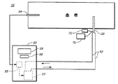
図1は、本発明に係る温度制御システム10を示している。患者の中心血液供給部へのアクセスを提供する中心静脈線カテーテル20は、患者と熱交換関係を持って配置される。循環する熱交換用流体(図示せず)が中心静脈線カテーテル20に供給され、この熱交換用流体の温度は、所望の患者標的体温または体温範囲を達成するため、フィードバック機構により自動的に制御される。フィードバック機構は、プローブ54を用いて患者の体温を検知する手段を含んでおり、そして、このプローブの出力が、温度制御モジュール50に収容された温度コントローラー55へ供給される。温度コントローラー55は、検知された温度が上述の望ましい温度あるいは温度範囲から逸脱しているかどうかを決定し、その逸脱の方向に応じて熱交換用流体を加熱もしくは冷却するため、熱制御ユニット57を選択的に起動する。以降でもっと詳細に説明されているように、中心静脈線カテーテル20は多内腔式の装置であり、それらの内腔のうちの少なくとも2つは、カテーテルの熱交換エレメントへの熱交換用流体のフロー用に、及び、その熱交換エレメントからの熱交換用流体のフロー用に設けられている。その他の1つもしくはそれ以上の内腔は、特定の適用形態に応じて、液体の注入や、薬物の送給、あるいはガイドワイヤーの支持等、異なる用途で使用することができる。それらの内腔の好適な個数は3ないし5個であるが、その他の個数も可能である。
FIG. 1 shows a
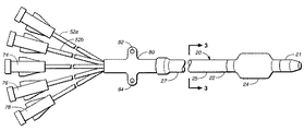
図2乃至4は、中心静脈線カテーテル20をさらに詳しく示しており、この中心静脈線カテーテルは、患者の体内、好適には鎖骨下静脈または頸静脈内への挿入に適した全体的に円筒形の実質上細長の構造体である。中心静脈線カテーテル20は、それの様々な内腔32,34,42,44及び46を画定するあらゆる既知のポリマー材料23から形成することができる。ナイロン,ポリエチレン及びPEBAX等の他の材料も使用することができるが、好適な材料はポリウレタンである。適当な材料23を選択する際に考慮すべき事項は、生体適合性、可撓性、温度変化適合性及び座屈抵抗性を含む。
FIGS. 2-4 illustrate the central
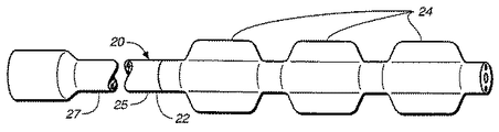
カテーテル20の移植可能な遠位側端部22には、このカテーテルの幅の周りに放射状に配置された、流体を担持する膨張可能なバルーン24等の熱交換エレメントが設けられている。バルーン24は可撓性の先端部21に近接配置されており、そして、このバルーンは、一枚のシート材料38から形成することもできるし、あるいは、管材料を押し出し加工して所望の形及びサイズの成形バルーンを形成し、次いで、それをシャフト25に結合するか、もしくは他の方法で固定して空洞36を形成することにより作成することもできる。図示されているように、バルーン24は、カテーテルのシャフト部分25よりも有意に大きな直径を有するものとして示されている。例えば、幾つかの適用形態では、膨張したバルーンの直径がシャフト25の直径の3倍以上になるように設計される。一つの好適な実施態様では、バルーンの直径は、4ミリメートルないし10ミリメートル(4mm〜10mm)である。好適には、バルーンの直径は、代表的な大静脈の直径の40%〜60%を越えないように選択される。あるケースでは、熱交換用流体のフローを容易化するため、シャフト25の寸法を最大化するのが望ましい場合があることを理解すべきである。これは、バルーン24内の流体の体積を最小化することにもなり、これにより、より迅速な熱交換が促進されよう。更に、本発明と共に、前述の2件の同時係属特許出願公報に開示されているような、これらに限定するものではないが、螺旋形または溝付き形を含む無数のバルーン形状を利用し得ることも理解されよう。選択される特定の形状は、適用形態や、所望の熱交換特性及び他の特性に依存するであろう。一つの好適な実施態様では、バルーン24は、ウレタン、ナイロンまたはPETから作成され、そして、薄肉であり、即ち、このバルーン24の肉厚は、3ミル未満、より好適には1.5ミル未満である。また、そのバルーン24は、好適には、ヘパリン等の抗凝固物質や抗菌物質でコーティングされる。
The implantable
バルーン24は、中心静脈カテーテルのうちの患者に挿管される部分の全長にわたって拡張できることを理解すべきである。典型的には、この長さは約15cmである。そのような状況下において、このバルーンの直径は、通常の中心静脈カテーテルの直径よりも大きい必要はなく、例えば、バルーンの直径は12Frenchや10Frenchであってよく、もしくは、7.5French等、更に小さくてもよい。もっと広く、バルーンの直径は、バルーンがカテーテルの挿管部分の全長にわたって拡張するとき、5〜13Frenchであってよい。以下で詳述されている如くに複数のバルーンが使用されるように配列されているケースでは、これらのバルーンが全体として、カテーテルの挿管部分の全長を覆うようにすることができる。即ち、それぞれが約7.5cmの2個のバルーン、または、3個の5cmのバルーン等、を使用することができる。
It should be understood that the
図3及び図4を参照することでより明瞭になるように、カテーテル20には一対の内腔32と34が形成されており、そのうちの内腔32は、バルーン24にカテーテル20中を循環させられる熱交換用流体を供給する流入チャンネルとして機能し、もう一方の内腔34は、バルーン24からの熱交換用流体をカテーテルへ戻す流出チャンネルとして機能する。選定される特定の熱交換用流体は、万一誤って破裂した際に患者に害が及ぶことを避けるため、生体適合性であることが好ましい。そのような候補となる材料は、無菌生理食塩水及び二酸化炭素ガスを含み、その他にも、適当な粘度、熱交換特性及び材料適合特性を有する他の流体も使用することができる。生体適合性ではないため、望ましさは劣るものの、フレオンも代りに使用することができる。
As will become clearer with reference to FIGS. 3 and 4, the
バルーン24は、インレットポート26及びアウトレットポート28等の複数のポートを介して、内腔32及び34と流体的に連通している。カテーテル20内を循環させられる熱交換用流体は、内腔32からインレットポート26を通じて空洞36内へ入った後、アウトレットポート28を通じて空洞36から内腔34へ出る。空洞36内にある間、中心静脈線カテーテル20の外部で遠隔的に冷却された熱交換用流体は、バルーン24の壁部を形成するシート材料38の内面に低温の流体を供給すべく機能する。このシート材料38を通じて、バルーン24の外側を流れる血液等の体液との熱輸送が起こり、これにより、患者の身体の効果的な冷却と、発熱の影響の抑制が行われる。このため、インレットポート26は、アウトレットポート28の遠位側に配置されている。
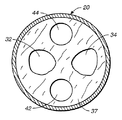
また、内腔32と34の横断面形状に関して特定の考慮をなすことによっても効果的な熱輸送が促進される。特に、図3から分かるように、内腔32と34は、そこを通って流れる流体の体積を最大化するように設計されている。これは、カテーテル20内で円周的に最大の弧長を占めるように、それらの内腔を三日月形の横断面形状にすることにより達成される。しかし、上述の三日月形横断面形状は、シャフト部分25におけるカテーテル20の外部との望ましくない熱交換をもたらす表面積の増大をも伴うため、この体積の最大化は、熱効率を犠牲にする心配がある。この心配を取り除くため、図4に示されている好適な横断面形状では、カテーテルの構造用材料37で、内腔32と34が、カテーテル20の外部からもっと効果的に絶縁されている。
Effective heat transport is also facilitated by making specific considerations regarding the cross-sectional shape of the
バルーン24の空洞36内への流体の流入、及び空洞からの流体の流出を容易化するため、アウトレットポート28をインレットポート26よりも大きくし、これにより、熱交換用流体がバルーン24を出るときに遭遇する抵抗を低減することができる。この相対的なサイズの相違は、本発明の別の実施態様で考えられているような、カテーテル20に複数のバルーンが供給されているときに特に重要になる。特に、単一のバルーン24に関して説明されているが、図6に示されているように、シャフト25の長さ方向に沿って軸状に配置された幾つかのそのようなバルーンを供給できることが理解されよう。複数のバルーンを用いる形態の一つの利点は、熱交換用流体の流れ及び温度を、カテーテル20の熱交換領域の全長に沿って一層簡単に制御できることである。熱交換用流体は、血液との熱交換に入る前が最も冷たく、そして、血液との熱交換後に最も暖かくなるということを認識した上で、流速及び流量だけでなく、それぞれのバルーン24内での流れの方向も有利に制御することができる。複数のバルーンを用いる設計の別な利点は、カーブした血管系内に置かれたときのカテーテルの湾曲及び屈曲能力である。
In order to facilitate inflow of fluid into and out of
カテーテル20は、内腔32と34の他に、2つもしくは3つの内腔42,44及び46を備えている。それらの内腔42,44及び46は、化学療法等の薬剤や、液体、及び栄養剤の注入、サンプリング用シリンジへのアクセス、及び、患者をモニタリングするためのサーミスター等の様々なセンサーの収容等を含む多数の機能を果たすことができ、従って、一般的には、特定の適用形態により指定された通りの中心血液供給部へのアクセスを提供する。更に、例えばガイドワイヤーを一層良好な状態で支持するため、中央の内腔44を、両側の内腔42及び46とは異なる直径になしてもよい。それらの内腔は、実質的に、近位側端部27から遠位側端部22まで、カテーテル20の全長にわたって延在している。設ける内腔の個数は、個々の適用形態に合わせて変えることができる。
また、熱交換エレメントは、必ずしもバルーン24等のバルーンの形態でなくてもよいことが理解されよう。むしろ、そこを通じて熱交換用流体が循環させられる可撓性中空ファイバーアレイ等の配列を用いることもでき、この場合、熱交換相互作用に寄与する表面積を大きくすることができる。本発明で使用できる他の熱交換エレメントの配列と共に、そのような配列が、参照としてそっくりそのまま本明細書に組込まれている前述の同時係属特許出願第09/133,813号に開示されている。中空ファイバー型熱交換エレメントの形態が図7に示されている。中空ファイバー58は、熱交換流体用の内側の内腔62から流体を受け入れ、そして、この流体を、カテーテル20の熱交換流体用の外側の内腔64へ戻す。様々な流体の送給を容易化するため、及び、他の用途で、内腔66等の付加的な内腔も設けられている。中空ファイバー型熱交換エレメント配列の重要な利点は、この熱交換エレメントの長さ方向に沿ったあらゆる箇所で、例えばポート68を介して、内腔66等の内側の内腔と血液との連絡が可能になることである。図2を相互に参照しながら再度図1を参照すると、カテーテル20は、温度制御モジュール50と協働して機能する。冷却剤のインレット及びアウトレット用フィッティング52a,52b(図2)を含む配管系52(図1)は、例えば隔膜ポンプ、ブラダーポンプ、ピストンポンプ、ぜん動ポンプ等の既知のポンピング手段(図示せず)を用いて、閉じた流体回路内の温度制御モジュール50とカテーテル20との間で流体を搬送し、流体はこの閉じた流体回路を通じて循環させられる。それらのインレット及びアウトレット用フィッティング52a,52bは、それぞれ、温度制御ユニット57からカテーテル20の内腔32,34への流体的な連通経路を確立することを理解すべきである。温度制御モジュール50には、適切な情報を記憶するメモリー(図示せず)を有するマイクロプロセッサーであってよい温度コントローラー55が設けられており、プローブ54から患者の体温信号を受信する。冷却用流体と熱交換関係にある冷却装置及び/又は加熱装置であってよい温度制御ユニット57への入力を制御することにより、温度コントローラー55は、所望の標的温度もしくは温度範囲に応じて、その熱交換用流体の温度を自動的に調節する。その標的温度または温度範囲は、キーボード56等の入力装置を用いて登録することができる。LCD58等の表示装置は、システムの操作及び/又は患者の状態に関する指示を呈示するための様々なパラメーターを表示する。
It will also be appreciated that the heat exchange element need not be in the form of a balloon, such as
好適には、その標的温度は正常な体温になるべく選定され、そして、例えば発熱の発現により誘発されたこの温度からの逸脱は、プローブ54で検知され、本発明のシステムにより自動的に矯正される。温度の矯正は、例えば、温度制御モジュール50の温度制御ユニット57を起動することにより果たされる。冷却する適用形態の場合、温度制御ユニット57は、循環する流体の冷却をもたらし、ついには、プローブ54でモニタリングされている患者のコア体温の冷却をもたらす。正常な温度が達成されると、温度制御ユニット57は、スイッチが自動的に切られるか、あるいは、温度コントローラー55によりその冷却効果を低減することができる。正確な温度調節を果たすため、システムのコンポーネント及びシステムの時定数からなる性能パラメーターを考慮に入れた好ましい温度制御アルゴリズムが、温度コントローラー55により実行される。より有利な温度制御形態では、モジュール50は、温度制御ユニット57の一部として更に加熱装置を備えていてもよく、そして、例えば所望の標的温度または温度範囲からのオーバーシューティングを防ぐため、更には、ある状況下において高体温を誘発するため、プローブ54からのフィードバックを利用してこの加熱装置を自動的に起動することもできる。プローブ54は、例えば直腸等の患者の身体のいずれかの部分からの温度フィードバック信号を得るために使用することもできるし、あるいは、プローブ54がこの流体回路のいずれかの箇所における温度情報をもたらし、次いで、その情報を、本システムの異なる部分の熱伝導率や、体重、身長、年齢等の患者情報などの既知のパラメーターを用いて、患者のコア体温と関係付けることもできることが理解されよう。更に、ある環境下においては、正確度を改善するため、患者及び/又は本システムからの読み取り値の組み合わせを得るために1つより多くのプローブを用いることもできる。
Preferably, the target temperature is selected to be normal body temperature, and deviations from this temperature, e.g. induced by the development of fever, are detected by the
本発明によれば、フィードバック機構を用いて患者を所望の温度条件に維持することができる。特に、本システムは、正常体温範囲であってよい許容可能な温度範囲からのあらゆる温度上の逸脱を制御するために使用することができ、そこでは、上述の予め定められた範囲からのこの検知された逸脱状態に応じて、プローブ54が患者の身体の冷却または加熱を誘発するであろう。更に、この逸脱は、一般的に、その患者の医療担当者が承知しておくべき特定の生理学的活動の指標であるため、本システムの運転を、この生理学的活動が起こっていることの指示手段として利用することができる。例えば、患者のコア体温が上昇したために温度制御ユニット57の冷却運転が起動された場合、本システムを構成する冷却コンポーネントの作業負荷の増大として反映される本システムの冷却活動は、この時、その患者の身体が発熱状態に入ろうとしているのを、例えばアラームまたは他の状況インジケーター装置(図示せず)を用いて音響信号または視覚的な信号により医療担当者に指示するために使用される。その後、適切な処置を講じることができる。この指示を発するため、温度フィードバックの傾きの符号とその傾き等の作業負荷以外のパラメーターを使用することもできる。代替的に、プローブ54で検知されたもの等の患者の体温の直接的な指標を用いることもできる。このようにして、例えば約1時間から約29日間、もしくはそれ以上の日数等、長期間にわたる本システムの使用を容易化することができる。
According to the present invention, a patient can be maintained at a desired temperature condition using a feedback mechanism. In particular, the system can be used to control any temperature deviation from an acceptable temperature range, which can be a normal body temperature range, where this detection from the predetermined range described above. Depending on the deviated condition made, the
図1と図2とを相互に参照すると、中心静脈カテーテル20は、温度制御ユニット57に接続されているのに加え、中心静脈コンポーネント70,72と、カテーテル20の選定された内腔42,44及び46との間の連絡を確立するため、図2から明らかなように、それぞれのフィッティング74,76及び78を介して、1つもしくはそれ以上の中心静脈コンポーネント70,72(図を見やすくする都合上、図1では2つの静脈コンポーネントのみが示されている)にも接続されている。本発明により想定されるものとして、中心静脈コンポーネント70,72は、薬物注入源、カテーテル20から流出する血液を受けるための血液容器、ガイドワイヤー等のうちの1つ以上で構成することができる。
Referring to FIGS. 1 and 2, the central
更に、図2に最も明らかに示されているように、カテーテル20は、このカテーテル20を患者に取り付けられるような形状になされたアンカーを含んでいる。より詳細には、一つの意図的実施態様では、このアンカーは、縫合用フィッティング80により構成される。縫合用フィッティング80は、カテーテル20と一体的に作成することもできるし、あるいは、カテーテルとは別のプラスチック製フィッティングとして作成し、取り巻くようにしてカテーテル20と係合させることもできる。図示されているように、この縫合用フィッティング80は2つの小穴82,84を含んでおり、これらの小穴に縫合糸を通して、患者の皮膚や、包帯、テープ、または患者に固定された他の構造物と係合することができる。代替的に、上述のアンカーを図8に示されているような一片のテープ86で構成し、このテープで本発明のカテーテルを患者に固定してもよい。更に、このアンカーは、患者と係合できる接着面を備え、且つ、本発明のカテーテルを受け入れられるような形状になされた構造物を含むプレート等の別の固定装置も含むことができる。ここで理解されるように、中心静脈カテーテルは典型的には長期間留置することが意図されているため、中心静脈カテーテルでは、アンカーは、カテーテルを患者に保持するものであることが望ましい。
In addition, as best shown in FIG. 2, the
以上は本発明の例示的な実施態様の説明であって、何ら限定することを意図したものではない。当業者が、請求項に記載されている通りの本発明の精神及び範囲から逸脱することなく、そこへ変更をなし得ることは明白であろう。 The foregoing is a description of exemplary embodiments of the invention and is not intended to be limiting in any way. It will be apparent to those skilled in the art that modifications may be made thereto without departing from the spirit and scope of the invention as set forth in the claims.
10:温度制御システム
20:中心静脈線カテーテル
21:先端部
22:遠位側端部
24:バルーン
25:シャフト
26:インレットポート
28:アウトレットポート
32:内腔
34:内腔
36:空洞
42:内腔
44:内腔
46:内腔
50:温度制御モジュール
52:配管系
54:プローブ
55:温度コントローラ
57:温度制御ユニット
58:中空ファイバー
62:内側の内腔
64:外側の内腔
80:縫合用フィティング(アンカー)
82:小穴
84:小穴
86:テープ
10: temperature control system 20: central venous catheter 21: tip 22: distal end 24: balloon 25: shaft 26: inlet port 28: outlet port 32: lumen 34: lumen 36: cavity 42: inside Cavity 44: Lumen 46: Lumen 50: Temperature control module 52: Piping system 54: Probe 55: Temperature controller 57: Temperature control unit 58: Hollow fiber 62: Inner lumen 64: Outer lumen 80: For suture Fitting (anchor)
82: Small hole 84: Small hole 86: Tape
Claims (3)
患者の身体との熱交換を生じさせるために遠位部に沿って少なくとも延在する少なくとも一つの熱交換要素と、を備える、中心静脈ラインアクセスを確立するように構成された中心静脈ラインカテーテルであって、
前記少なくとも一つの熱交換要素は、中心静脈システムとの熱交換を生じさせるためのものであり、
中心静脈ラインカテーテルは、中心静脈ラインカテーテルの長期留置を可能とするために中心静脈ラインカテーテルを患者の皮膚に取り付けるように構成された少なくとも一つの中心静脈ライン縫合アンカーを含むことを特徴とする中心静脈ラインカテーテル。 At least one elongated structure having a proximal portion and a distal portion and forming at least one first lumen in communication with the exterior of the elongated structure at the proximal portion and the distal portion;
A central venous line catheter configured to establish central venous line access comprising: at least one heat exchanging element extending at least along the distal portion to effect heat exchange with a patient's body; There,
The at least one heat exchange element is for causing heat exchange with a central venous system;
A central venous line catheter includes at least one central venous line suture anchor configured to attach the central venous line catheter to a patient's skin to allow long-term placement of the central venous line catheter. Venous line catheter.
中心静脈システムとの熱交換を生じさせるために遠位部に沿って少なくとも延在して、第一ルーメンを通じて熱交換流体を受け取る少なくとも一つの熱交換要素と、
熱交換流体を運ぶことなく、中心静脈ライン目的で使用可能である第二ルーメンと、を備える中心静脈ラインカテーテルであって、
少なくとも一つの中心静脈コンポーネントと流体連通する第二ルーメンを通じて、薬剤が注入されるか血液が採取されることを特徴とする中心静脈ラインカテーテル。 At least forming a central venous line access and having at least one first lumen having a proximal portion and a distal portion and in communication with the exterior of the elongated structure at the proximal portion and the distal portion One elongated structure,
At least one heat exchange element extending at least along the distal portion to effect heat exchange with the central venous system and receiving a heat exchange fluid through the first lumen;
A central venous line catheter comprising a second lumen that can be used for central venous line purposes without carrying a heat exchange fluid,
A central venous line catheter wherein a drug is infused or blood is collected through a second lumen in fluid communication with at least one central venous component.
細長い構造体と細長い熱交換要素との間で血液が流れることを可能にする細長い構造体と係合して、第一ルーメンから熱交換流体を受け取り、患者との熱交換を生じさせるために少なくとも遠位部に沿って延在する複数の中空の細長い熱交換要素と、を備えることを特徴とする中心静脈ラインカテーテル。 At least forming a central venous line access and having at least one first lumen having a proximal portion and a distal portion and in communication with the exterior of the elongated structure at the proximal portion and the distal portion One elongated structure,
Engage with the elongate structure that allows blood to flow between the elongate structure and the elongate heat exchange element to receive heat exchange fluid from the first lumen and to generate heat exchange with the patient at least A central venous line catheter comprising a plurality of hollow elongate heat exchange elements extending along a distal portion.
Applications Claiming Priority (2)
| Application Number | Priority Date | Filing Date | Title |
|---|---|---|---|
| US25310999A | 1999-02-19 | 1999-02-19 | |
| US09/253,109 | 1999-02-19 |
Related Parent Applications (1)
| Application Number | Title | Priority Date | Filing Date |
|---|---|---|---|
| JP2000599457A Division JP4248750B2 (en) | 1999-02-19 | 2000-02-18 | Central venous catheter with temperature control system |
Related Child Applications (1)
| Application Number | Title | Priority Date | Filing Date |
|---|---|---|---|
| JP2012091116A Division JP5636020B2 (en) | 1999-02-19 | 2012-04-12 | catheter |
Publications (2)
| Publication Number | Publication Date |
|---|---|
| JP2009018210A JP2009018210A (en) | 2009-01-29 |
| JP5116633B2 true JP5116633B2 (en) | 2013-01-09 |
Family
ID=22958897
Family Applications (3)
| Application Number | Title | Priority Date | Filing Date |
|---|---|---|---|
| JP2000599457A Expired - Fee Related JP4248750B2 (en) | 1999-02-19 | 2000-02-18 | Central venous catheter with temperature control system |
| JP2008279870A Expired - Fee Related JP5116633B2 (en) | 1999-02-19 | 2008-10-30 | Central venous catheter |
| JP2012091116A Expired - Lifetime JP5636020B2 (en) | 1999-02-19 | 2012-04-12 | catheter |
Family Applications Before (1)
| Application Number | Title | Priority Date | Filing Date |
|---|---|---|---|
| JP2000599457A Expired - Fee Related JP4248750B2 (en) | 1999-02-19 | 2000-02-18 | Central venous catheter with temperature control system |
Family Applications After (1)
| Application Number | Title | Priority Date | Filing Date |
|---|---|---|---|
| JP2012091116A Expired - Lifetime JP5636020B2 (en) | 1999-02-19 | 2012-04-12 | catheter |
Country Status (8)
| Country | Link |
|---|---|
| EP (1) | EP1029520B1 (en) |
| JP (3) | JP4248750B2 (en) |
| AT (2) | ATE342024T1 (en) |
| AU (1) | AU763293B2 (en) |
| CA (1) | CA2368243C (en) |
| DE (2) | DE69902509T2 (en) |
| ES (1) | ES2183477T3 (en) |
| WO (1) | WO2000048670A1 (en) |
Families Citing this family (38)
| Publication number | Priority date | Publication date | Assignee | Title |
|---|---|---|---|---|
| US6383210B1 (en) | 2000-06-02 | 2002-05-07 | Innercool Therapies, Inc. | Method for determining the effective thermal mass of a body or organ using cooling catheter |
| US6974463B2 (en) | 1999-02-09 | 2005-12-13 | Innercool Therapies, Inc. | System and method for patient temperature control employing temperature projection algorithm |
| US6585752B2 (en) | 1998-06-23 | 2003-07-01 | Innercool Therapies, Inc. | Fever regulation method and apparatus |
| US6312452B1 (en) | 1998-01-23 | 2001-11-06 | Innercool Therapies, Inc. | Selective organ cooling catheter with guidewire apparatus and temperature-monitoring device |
| US6325818B1 (en) | 1999-10-07 | 2001-12-04 | Innercool Therapies, Inc. | Inflatable cooling apparatus for selective organ hypothermia |
| US6379378B1 (en) | 2000-03-03 | 2002-04-30 | Innercool Therapies, Inc. | Lumen design for catheter |
| US6364899B1 (en) | 1998-01-23 | 2002-04-02 | Innercool Therapies, Inc. | Heat pipe nerve cooler |
| US6602276B2 (en) | 1998-03-31 | 2003-08-05 | Innercool Therapies, Inc. | Method and device for performing cooling- or cryo-therapies for, e.g., angioplasty with reduced restenosis or pulmonary vein cell necrosis to inhibit atrial fibrillation |
| US6685732B2 (en) | 1998-03-31 | 2004-02-03 | Innercool Therapies, Inc. | Method and device for performing cooling- or cryo-therapies for, e.g., angioplasty with reduced restenosis or pulmonary vein cell necrosis to inhibit atrial fibrillation employing microporous balloon |
| US6530946B1 (en) | 1998-04-21 | 2003-03-11 | Alsius Corporation | Indwelling heat exchange heat pipe catheter and method of using same |
| US6419643B1 (en) | 1998-04-21 | 2002-07-16 | Alsius Corporation | Central venous catheter with heat exchange properties |
| US6368304B1 (en) * | 1999-02-19 | 2002-04-09 | Alsius Corporation | Central venous catheter with heat exchange membrane |
| US6620189B1 (en) | 2000-02-28 | 2003-09-16 | Radiant Medical, Inc. | Method and system for control of a patient's body temperature by way of a transluminally insertable heat exchange catheter |
| US6673098B1 (en) | 1998-08-24 | 2004-01-06 | Radiant Medical, Inc. | Disposable cassette for intravascular heat exchange catheter |
| US7914564B2 (en) | 1999-02-09 | 2011-03-29 | Innercool Therapies, Inc. | System and method for patient temperature control employing temperature projection algorithm |
| US6585692B1 (en) | 1999-02-19 | 2003-07-01 | Alsius Corporation | Method and system for patient temperature management and central venous access |
| US6554797B1 (en) | 1999-02-19 | 2003-04-29 | Alsius Corporation | Method and system for patient temperature management and central venous access |
| AU2001246754A1 (en) * | 2000-09-28 | 2002-04-08 | Alsius Corporation | Central venous line catheter and method of preparing the same for the use |
| WO2002055129A2 (en) * | 2000-11-07 | 2002-07-18 | Innercool Therapies, Inc. | Fever regulation method and apparatus |
| US6719723B2 (en) | 2000-12-06 | 2004-04-13 | Innercool Therapies, Inc. | Multipurpose catheter assembly |
| WO2002058606A1 (en) * | 2001-01-24 | 2002-08-01 | Alsius Corporation | Central venous catheter with heat exchange properties |
| US6450987B1 (en) | 2001-02-01 | 2002-09-17 | Innercool Therapies, Inc. | Collapsible guidewire lumen |
| US6679906B2 (en) | 2001-07-13 | 2004-01-20 | Radiant Medical, Inc. | Catheter system with on-board temperature probe |
| US6800068B1 (en) | 2001-10-26 | 2004-10-05 | Radiant Medical, Inc. | Intra-aortic balloon counterpulsation with concurrent hypothermia |
| US7070612B1 (en) * | 2005-02-23 | 2006-07-04 | Alsius Corporation | System and method for bringing hypothermia rapidly onboard |
| AU2006239290B2 (en) | 2005-04-27 | 2012-05-10 | Zoll Circulation, Inc. | System for adjusting the temperature of a patient |
| US20180311071A1 (en) | 2005-10-21 | 2018-11-01 | Daniel R. BURNETT | Method and apparatus for peritoneal oxygenation |
| US20070093697A1 (en) | 2005-10-21 | 2007-04-26 | Theranova, Llc | Method and apparatus for detection of right to left shunting in the cardiopulmonary vasculature |
| US7236694B1 (en) * | 2006-01-27 | 2007-06-26 | Jacques Chammas | Blood and biological fluid warmer |
| JP2010523230A (en) | 2007-04-05 | 2010-07-15 | ベロメディックス,インク | Automatic treatment system and method |
| AU2008275158A1 (en) | 2007-07-09 | 2009-01-15 | Velomedix, Inc | Hypothermia devices and methods |
| WO2012006625A2 (en) | 2010-07-09 | 2012-01-12 | Velomedix, Inc. | Method and apparatus for pressure measurement |
| US9278023B2 (en) | 2012-12-14 | 2016-03-08 | Zoll Circulation, Inc. | System and method for management of body temperature |
| DE102013102929A1 (en) * | 2013-03-22 | 2014-09-25 | Acandis Gmbh & Co. Kg | Temperature measuring device for intravascular applications, cooling catheter with a temperature measuring device and method for temperature measurement |
| CA2916032C (en) * | 2013-07-25 | 2021-05-11 | Merit Medical Systems, Inc. | Balloon catheter systems and methods |
| EP2932946A1 (en) * | 2014-04-17 | 2015-10-21 | seiratherm GmbH | Apparatus, system and method for controlling a temperature of a patient |
| US9709609B2 (en) | 2014-07-14 | 2017-07-18 | Covidien Lp | Systems and methods for improving the range of sensor systems |
| CA3059407A1 (en) * | 2017-04-07 | 2018-10-11 | Palmera Medical, Inc. | Tissue cooling device comprising a thermal member in fluid connection with a cooling unit |
Family Cites Families (12)
| Publication number | Priority date | Publication date | Assignee | Title |
|---|---|---|---|---|
| US3425419A (en) * | 1964-08-08 | 1969-02-04 | Angelo Actis Dato | Method of lowering and raising the temperature of the human body |
| US5151100A (en) * | 1988-10-28 | 1992-09-29 | Boston Scientific Corporation | Heating catheters |
| US4897082A (en) * | 1989-03-20 | 1990-01-30 | Becton, Dickinson And Company | Apparatus for providing a suture tab |
| US5549559A (en) * | 1990-03-22 | 1996-08-27 | Argomed Ltd. | Thermal treatment apparatus |
| US5624392A (en) * | 1990-05-11 | 1997-04-29 | Saab; Mark A. | Heat transfer catheters and methods of making and using same |
| US5037383A (en) * | 1990-05-21 | 1991-08-06 | Northwestern University | Intravascular lung assist device and method |
| US5498261A (en) * | 1991-12-20 | 1996-03-12 | Advanced Cardiovascular Systems, Inc. | Thermal angioplasty system |
| US5269758A (en) * | 1992-04-29 | 1993-12-14 | Taheri Syde A | Intravascular catheter and method for treatment of hypothermia |
| US5837003A (en) * | 1993-02-10 | 1998-11-17 | Radiant Medical, Inc. | Method and apparatus for controlling a patient's body temperature by in situ blood temperature modification |
| US5545195A (en) * | 1994-08-01 | 1996-08-13 | Boston Scientific Corporation | Interstitial heating of tissue |
| JPH10127777A (en) * | 1996-10-31 | 1998-05-19 | Sumitomo Bakelite Co Ltd | Pharmaceutical liquid injecting port |
| JPH10305103A (en) * | 1997-05-08 | 1998-11-17 | Nippon Sherwood Medical Ind Ltd | Catheter fixing tool |
-
1999
- 1999-04-06 EP EP99201080A patent/EP1029520B1/en not_active Expired - Lifetime
- 1999-04-06 AT AT02000778T patent/ATE342024T1/en not_active IP Right Cessation
- 1999-04-06 ES ES99201080T patent/ES2183477T3/en not_active Expired - Lifetime
- 1999-04-06 DE DE69902509T patent/DE69902509T2/en not_active Expired - Lifetime
- 1999-04-06 AT AT99201080T patent/ATE222081T1/en not_active IP Right Cessation
- 1999-04-06 DE DE69933587T patent/DE69933587T2/en not_active Expired - Lifetime
-
2000
- 2000-02-18 JP JP2000599457A patent/JP4248750B2/en not_active Expired - Fee Related
- 2000-02-18 CA CA002368243A patent/CA2368243C/en not_active Expired - Lifetime
- 2000-02-18 WO PCT/US2000/004306 patent/WO2000048670A1/en active IP Right Grant
- 2000-02-18 AU AU37021/00A patent/AU763293B2/en not_active Expired
-
2008
- 2008-10-30 JP JP2008279870A patent/JP5116633B2/en not_active Expired - Fee Related
-
2012
- 2012-04-12 JP JP2012091116A patent/JP5636020B2/en not_active Expired - Lifetime
Also Published As
| Publication number | Publication date |
|---|---|
| AU763293B2 (en) | 2003-07-17 |
| JP2002538857A (en) | 2002-11-19 |
| JP4248750B2 (en) | 2009-04-02 |
| JP5636020B2 (en) | 2014-12-03 |
| DE69902509D1 (en) | 2002-09-19 |
| AU3702100A (en) | 2000-09-04 |
| CA2368243A1 (en) | 2000-08-24 |
| EP1029520B1 (en) | 2002-08-14 |
| DE69902509T2 (en) | 2003-03-27 |
| ATE222081T1 (en) | 2002-08-15 |
| JP2009018210A (en) | 2009-01-29 |
| DE69933587D1 (en) | 2006-11-23 |
| ES2183477T3 (en) | 2003-03-16 |
| DE69933587T2 (en) | 2007-08-16 |
| WO2000048670A1 (en) | 2000-08-24 |
| EP1029520A1 (en) | 2000-08-23 |
| CA2368243C (en) | 2009-09-29 |
| JP2012130808A (en) | 2012-07-12 |
| ATE342024T1 (en) | 2006-11-15 |
Similar Documents
| Publication | Publication Date | Title |
|---|---|---|
| JP5116633B2 (en) | Central venous catheter | |
| US6520933B1 (en) | Central venous line cooling catheter having a spiral-shaped heat exchange member | |
| US6620131B2 (en) | Dual balloon central venous line catheter temperature control system | |
| US6733517B1 (en) | Angling introducer sheath for catheter having temperature control system | |
| US8313461B2 (en) | Method for a central venous line catheter having a temperature control system | |
| US6645234B2 (en) | Cardiovascular guiding catheter with heat exchange properties and methods of use | |
| US6719724B1 (en) | Central venous line catheter having multiple heat exchange elements and multiple infusion lumens | |
| US6716236B1 (en) | Intravascular catheter with heat exchange element having inner inflation element and methods of use | |
| US8343097B2 (en) | Systems and methods for intravascular cooling | |
| US20020022823A1 (en) | Method and system for treating stroke using hypothermia | |
| US20030060761A1 (en) | Kit of parts including a heat exchange catheter for treating heart malady | |
| EP1205167B1 (en) | Central venous line catheter having temperature control system | |
| EP1328223A2 (en) | Kit of parts including a central venous line catheter having a temperature control system |
Legal Events
| Date | Code | Title | Description |
|---|---|---|---|
| A621 | Written request for application examination |
Free format text: JAPANESE INTERMEDIATE CODE: A621 Effective date: 20081030 |
|
| A711 | Notification of change in applicant |
Free format text: JAPANESE INTERMEDIATE CODE: A711 Effective date: 20091014 |
|
| A131 | Notification of reasons for refusal |
Free format text: JAPANESE INTERMEDIATE CODE: A131 Effective date: 20110517 |
|
| A521 | Request for written amendment filed |
Free format text: JAPANESE INTERMEDIATE CODE: A523 Effective date: 20110816 |
|
| A131 | Notification of reasons for refusal |
Free format text: JAPANESE INTERMEDIATE CODE: A131 Effective date: 20120214 |
|
| A521 | Request for written amendment filed |
Free format text: JAPANESE INTERMEDIATE CODE: A523 Effective date: 20120412 |
|
| TRDD | Decision of grant or rejection written | ||
| A01 | Written decision to grant a patent or to grant a registration (utility model) |
Free format text: JAPANESE INTERMEDIATE CODE: A01 Effective date: 20121002 |
|
| A01 | Written decision to grant a patent or to grant a registration (utility model) |
Free format text: JAPANESE INTERMEDIATE CODE: A01 |
|
| A61 | First payment of annual fees (during grant procedure) |
Free format text: JAPANESE INTERMEDIATE CODE: A61 Effective date: 20121016 |
|
| R150 | Certificate of patent or registration of utility model |
Free format text: JAPANESE INTERMEDIATE CODE: R150 Ref document number: 5116633 Country of ref document: JP Free format text: JAPANESE INTERMEDIATE CODE: R150 |
|
| FPAY | Renewal fee payment (event date is renewal date of database) |
Free format text: PAYMENT UNTIL: 20151026 Year of fee payment: 3 |
|
| R250 | Receipt of annual fees |
Free format text: JAPANESE INTERMEDIATE CODE: R250 |
|
| R250 | Receipt of annual fees |
Free format text: JAPANESE INTERMEDIATE CODE: R250 |
|
| R250 | Receipt of annual fees |
Free format text: JAPANESE INTERMEDIATE CODE: R250 |
|
| R250 | Receipt of annual fees |
Free format text: JAPANESE INTERMEDIATE CODE: R250 |
|
| LAPS | Cancellation because of no payment of annual fees |