JP5116543B2 - Inkjet printing device - Google Patents
Inkjet printing device Download PDFInfo
- Publication number
- JP5116543B2 JP5116543B2 JP2008104046A JP2008104046A JP5116543B2 JP 5116543 B2 JP5116543 B2 JP 5116543B2 JP 2008104046 A JP2008104046 A JP 2008104046A JP 2008104046 A JP2008104046 A JP 2008104046A JP 5116543 B2 JP5116543 B2 JP 5116543B2
- Authority
- JP
- Japan
- Prior art keywords
- roller
- fabric
- peeling
- endless belt
- printing apparatus
- Prior art date
- Legal status (The legal status is an assumption and is not a legal conclusion. Google has not performed a legal analysis and makes no representation as to the accuracy of the status listed.)
- Active
Links
- 238000007641 inkjet printing Methods 0.000 title claims description 23
- 238000007639 printing Methods 0.000 claims description 25
- 238000011144 upstream manufacturing Methods 0.000 claims description 14
- 239000000463 material Substances 0.000 claims description 11
- 238000004804 winding Methods 0.000 claims description 11
- 239000000853 adhesive Substances 0.000 claims description 4
- 230000001070 adhesive effect Effects 0.000 claims description 4
- 239000004744 fabric Substances 0.000 description 72
- 239000004753 textile Substances 0.000 description 12
- 238000001035 drying Methods 0.000 description 6
- 239000010410 layer Substances 0.000 description 4
- 229920001971 elastomer Polymers 0.000 description 3
- 239000005060 rubber Substances 0.000 description 3
- 239000004820 Pressure-sensitive adhesive Substances 0.000 description 2
- 239000013013 elastic material Substances 0.000 description 2
- 239000002184 metal Substances 0.000 description 2
- 229920000742 Cotton Polymers 0.000 description 1
- 229910000831 Steel Inorganic materials 0.000 description 1
- 229920006311 Urethane elastomer Polymers 0.000 description 1
- BZHJMEDXRYGGRV-UHFFFAOYSA-N Vinyl chloride Chemical compound ClC=C BZHJMEDXRYGGRV-UHFFFAOYSA-N 0.000 description 1
- 239000012790 adhesive layer Substances 0.000 description 1
- 238000010586 diagram Methods 0.000 description 1
- 230000000694 effects Effects 0.000 description 1
- 238000004519 manufacturing process Methods 0.000 description 1
- 238000000034 method Methods 0.000 description 1
- 229920003023 plastic Polymers 0.000 description 1
- 239000004033 plastic Substances 0.000 description 1
- 229920000728 polyester Polymers 0.000 description 1
- 238000003825 pressing Methods 0.000 description 1
- 239000011347 resin Substances 0.000 description 1
- 229920005989 resin Polymers 0.000 description 1
- 238000010020 roller printing Methods 0.000 description 1
- 238000007650 screen-printing Methods 0.000 description 1
- 229920002379 silicone rubber Polymers 0.000 description 1
- -1 silk Polymers 0.000 description 1
- 239000010959 steel Substances 0.000 description 1
Images


Classifications
-
- B—PERFORMING OPERATIONS; TRANSPORTING
- B41—PRINTING; LINING MACHINES; TYPEWRITERS; STAMPS
- B41J—TYPEWRITERS; SELECTIVE PRINTING MECHANISMS, i.e. MECHANISMS PRINTING OTHERWISE THAN FROM A FORME; CORRECTION OF TYPOGRAPHICAL ERRORS
- B41J3/00—Typewriters or selective printing or marking mechanisms characterised by the purpose for which they are constructed
- B41J3/407—Typewriters or selective printing or marking mechanisms characterised by the purpose for which they are constructed for marking on special material
- B41J3/4078—Printing on textile
-
- B—PERFORMING OPERATIONS; TRANSPORTING
- B41—PRINTING; LINING MACHINES; TYPEWRITERS; STAMPS
- B41J—TYPEWRITERS; SELECTIVE PRINTING MECHANISMS, i.e. MECHANISMS PRINTING OTHERWISE THAN FROM A FORME; CORRECTION OF TYPOGRAPHICAL ERRORS
- B41J15/00—Devices or arrangements of selective printing mechanisms, e.g. ink-jet printers or thermal printers, specially adapted for supporting or handling copy material in continuous form, e.g. webs
- B41J15/04—Supporting, feeding, or guiding devices; Mountings for web rolls or spindles
- B41J15/048—Conveyor belts or like feeding devices
Landscapes
- Engineering & Computer Science (AREA)
- Textile Engineering (AREA)
- Treatment Of Fiber Materials (AREA)
- Coloring (AREA)
Description
本発明は、インクジェット捺染装置に関するものである。 The present invention relates to an ink jet textile printing apparatus.
従来、綿や絹、ポリエステルなどの布帛に捺染を行う装置として、スクリーン捺染装置やローラ捺染装置などが広く用いられていた。しかし、これらの捺染装置は、図柄毎にスクリーン枠や彫刻ローラ等を用意する必要があるが、スクリーン枠や彫刻ローラは高価であるために大量生産しなければ経済的な面からコストが合わないといった問題があった。これに対して、インクジェット捺染装置は、デジタルデータを変更するだけで図柄の変更に対応できるため、少量多品種の生産に向いているといった利点があり、近年広く用いられてきている。このインクジェット捺染装置は、例えば特許文献1の図1に示されるように、上流側と下流側に搬送ローラが設置されており、布帛を搬送するための搬送ベルトがこれら搬送ローラに巻回されている。この搬送ベルトによって搬送された布帛はプリンタ部によって捺染されるが、捺染時の布帛の平坦性を確保するために、搬送ベルト表面に粘着層を形成し、貼付ローラを用いて布帛を搬送ベルト上に貼り付けている。そして、捺染が終了した布帛は下流側の搬送ローラまで搬送されると送りローラ及び中間ローラを介して巻取ローラに巻き取られる。
しかしながら、上記インクジェット捺染装置は、布帛を搬送ベルト上に接着させているため、捺染が終了した布帛を搬送ベルトから剥離する必要がある。この剥離は、巻取ローラの布帛を巻き取る力によって布帛が搬送ベルトから引き剥がされているが、この剥離する際に布帛に大きな力が掛かってしまうので、薄地の布帛やニット製の布帛を使用した場合に、これらの仕上がり後の製品の糸目が曲がったり、伸長してしまい製品の品質が損なわれるといった問題があった。 However, since the above-described ink jet printing apparatus has the fabric adhered on the transport belt, it is necessary to peel the fabric after printing from the transport belt. In this peeling, the cloth is peeled off from the transport belt by the force of winding the cloth of the take-up roller. However, since a large force is applied to the cloth during the peeling, a thin cloth or a knit cloth is used. When used, there has been a problem that the yarns of these finished products are bent or stretched to deteriorate the quality of the product.
そこで、本発明は、薄地の布帛やニット製の布帛であっても製品の品質を損なうことなく捺染を行うことのできるインクジェット捺染装置を提供することを課題とする。 Therefore, an object of the present invention is to provide an inkjet printing apparatus that can perform printing without impairing the quality of a product even if it is a thin fabric or a knit fabric.
本発明に係るインクジェット捺染装置は、上記課題を解決するためになされたものであり、被捺染物を捺染するインクジェット捺染装置であって、被捺染物が貼り付く粘着面を有し、被捺染物を上流から下流に搬送するエンドレスベルトと、前記エンドレスベルトを駆動する上流側駆動ローラ及び下流側駆動ローラと、前記下流側駆動ローラの下流に設置された、被捺染物を巻き取る巻取ローラと、前記下流側駆動ローラと前記巻取ローラとの間に設置され、被捺染物をエンドレスベルトから剥離するよう回転駆動される剥離ローラと、を備えている。 An ink jet printing apparatus according to the present invention has been made to solve the above-mentioned problems, and is an ink jet printing apparatus for printing a printed material, which has an adhesive surface to which the printed material adheres, and has a printed material. An endless belt that conveys the belt from upstream to downstream, an upstream drive roller and a downstream drive roller that drive the endless belt, and a winding roller that is installed downstream of the downstream drive roller and winds up the printed material. And a peeling roller which is installed between the downstream drive roller and the winding roller and is driven to rotate so as to peel the printed material from the endless belt.
上記のように構成することによって、以下の効果を得ることができる。まず、従来のインクジェット捺染装置について説明すると、下流側駆動ローラまで搬送された布帛をエンドレスベルトから剥離させる際は、巻取ローラが回転して布帛を巻き取ることによって布帛をエンドレスベルトから剥離させていた。この巻取ローラは、布帛を巻き取るに連れて直径が大きくなるため、下流側駆動ローラと巻き取った布帛とが接触しないよう、下流側駆動ローラからある程度離れた距離のところに設置していた。これに対して、本発明に係るインクジェット捺染装置は、下流側駆動ローラと巻取ローラとの間に剥離ローラを有している。この剥離ローラは、布帛の進行と同期して回転するものであり、回転することによってエンドレスベルトから布帛を剥離することができる。このように、巻取ローラではなく剥離ローラによってエンドレスベルトから布帛を剥離しているため、エンドレスベルトから布帛を剥離する手段を剥離部分の近傍に設置することができ、布帛に掛かる引張力を低くすることができる。この結果、薄地の布帛やニット製の布帛の品質を損なうことなく捺染を行うことができる。 By configuring as described above, the following effects can be obtained. First, a conventional inkjet printing apparatus will be described. When the fabric conveyed to the downstream drive roller is peeled off from the endless belt, the winding roller rotates to wind up the fabric so that the fabric is peeled off from the endless belt. It was. Since the diameter of the take-up roller increases as the fabric is taken up, the take-up roller is installed at a distance from the downstream drive roller to some extent so that the downstream drive roller does not contact the wound fabric. . On the other hand, the ink jet textile printing apparatus according to the present invention has a peeling roller between the downstream drive roller and the winding roller. The peeling roller rotates in synchronization with the progress of the cloth, and the cloth can be peeled from the endless belt by rotating. As described above, since the fabric is peeled from the endless belt by the peeling roller instead of the winding roller, a means for peeling the fabric from the endless belt can be installed in the vicinity of the peeling portion, and the tensile force applied to the fabric is reduced. can do. As a result, printing can be performed without impairing the quality of the thin fabric or the knit fabric.
上記インクジェット捺染装置は種々の構成をとることができるが、例えば、下流側駆動ローラ及び剥離ローラに接触するように設置され、下流側駆動ローラの回転を剥離ローラへと伝えるカウンターローラをさらに備えていることが好ましい。この構成によれば、下流側駆動ローラの回転を利用して剥離ローラを回転させることができるため、剥離ローラの駆動源を別途設ける必要がなくなり、ひいてはインクジェット装置の小型化、低コスト化が可能となる。 The inkjet textile printing apparatus can take various configurations. For example, the inkjet textile printing apparatus further includes a counter roller that is installed so as to contact the downstream drive roller and the peeling roller and transmits the rotation of the downstream drive roller to the peeling roller. Preferably it is. According to this configuration, since the peeling roller can be rotated by using the rotation of the downstream driving roller, it is not necessary to provide a separate driving source for the peeling roller, and thus the size and cost of the ink jet apparatus can be reduced. It becomes.
また、上記カウンターローラは、剥離ローラの両端部に対応する位置において剥離ローラと接触していることが好ましい。通常、布帛は剥離ローラの中央部と接触し両端部とは接触しない。このため、カウンターローラを剥離ローラの両端部に接触させることで、カウンターローラによって剥離ローラを傷つける等しても、布帛に影響を及ぼすことがない。 The counter roller is preferably in contact with the peeling roller at positions corresponding to both ends of the peeling roller. Usually, the fabric contacts the central portion of the peeling roller and does not contact both ends. For this reason, even if it damages a peeling roller with a counter roller by making a counter roller contact the both ends of a peeling roller, a fabric is not affected.
また、上記カウンターローラは、回転不能に支持された軸部と、この軸部を中心に回転するよう設置されたローラ本体部とを有していることが好ましい。 The counter roller preferably has a shaft portion that is supported so as not to rotate, and a roller main body portion that is installed so as to rotate around the shaft portion.
同様に、上記剥離ローラも、回転不能に支持された軸部と、この軸部を中心に回転するローラ本体部とを有していることが好ましい。 Similarly, it is preferable that the peeling roller also has a shaft portion that is supported so as not to rotate and a roller main body portion that rotates around the shaft portion.
また、上記剥離ローラのローラ本体部を取り換え可能にすることが好ましい。この構成によれば、布帛の種類によって適切な材質により構成されたローラ本体部を用いることで、より適切に布帛をエンドレスベルトから布帛を剥離することができる。 Further, it is preferable that the roller main body of the peeling roller can be replaced. According to this configuration, the cloth can be more appropriately peeled from the endless belt by using the roller main body portion made of an appropriate material depending on the type of the cloth.
以上の説明から明らかなように、本発明によれば、薄地の布帛やニット製の布帛であっても、製品の品質を損なうことなく捺染を行うことのできるインクジェット捺染装置を提供することができる。 As is apparent from the above description, according to the present invention, it is possible to provide an ink jet printing apparatus capable of performing printing without impairing the quality of a product even with a thin fabric or a knit fabric. .
以下、本発明に係るインクジェット捺染装置の実施形態を図面に基づいて説明する。図1は、本実施形態に係るインクジェット捺染装置の全体を示す概略図である。なお、図1の右側を「上流側」、左側を「下流側」と称し、被捺染物は図1の右から左へと搬送される。 DESCRIPTION OF EXEMPLARY EMBODIMENTS Hereinafter, embodiments of an ink jet textile printing apparatus according to the invention will be described with reference to the drawings. FIG. 1 is a schematic diagram showing the entire inkjet printing apparatus according to the present embodiment. The right side in FIG. 1 is referred to as “upstream side” and the left side is referred to as “downstream side”, and the printed material is conveyed from right to left in FIG.
図1に示すように、インクジェット捺染装置1は、布帛(被捺染物)を巻出す巻出しローラC1と、布帛Cを搬送するエンドレスベルト2と、エンドレスベルト2を間欠的に駆動する上流側駆動ローラ3a及び下流側駆動ローラ3bとを備えている。上流側駆動ローラ3aの上方には、布帛Cをエンドレスベルト2上に貼り付ける貼付ローラ4が設置されている。また、上流側駆動ローラ3aと下流側駆動ローラ3bとの間には布帛Cを捺染するインクジェット捺染ユニット6が設置されている。そして、下流側駆動ローラ3bの下流にはエンドレスベルト2から布帛Cを剥離するための剥離ローラ7が設置されており、この剥離ローラ7によって剥離された布帛Cを乾燥する乾燥用ヒータプレート8、及び乾燥した布帛Cを巻き取る巻取ローラC2がさらに下流に設置されている。なお、これらインクジェット捺染装置1を構成する各部材は、支持枠9(図2、3等参照)によって支持されている。
As shown in FIG. 1, an
以下、インクジェット捺染装置1を構成する各部材について説明する。
Hereinafter, each member which comprises the inkjet
エンドレスベルト2は、金属製やゴム製、プラスチック製など種々の材料を採用可能であり、その外側表面に粘着面が形成されている。この粘着面は、例えば、感圧式の粘着剤をエンドレスベルト2の表面に塗布して形成することができる。このように、エンドレスベルト2の表面には粘着面が形成されているため、後述する貼付ローラ4で布帛Cをエンドレスベルト2上に押圧することによって、布帛Cをエンドレスベルト2上に貼り付けることができる。
The
上流側駆動ローラ3a及び下流側駆動ローラ3bは、モータ(図示省略)を駆動源として図1の反時計回りに間欠的に回転することで、エンドレスベルト2を矢印方向に間欠的に走行させる。なお、上流側駆動ローラ3aと下流側駆動ローラ3bとは、同じタイミングで且つ同じ速度で回転している。
The
貼付ローラ4は、エンドレスベルト2の上流側に設置されており、自重によって布帛Cをエンドレスベルト2に押圧している。この貼付ローラ4は、エンドレスベルト2と接触しているので、エンドレスベルト2が走行するとそれに伴って時計回りに回転するように構成されている。この貼付ローラ4は、軸部41と、ローラ本体部42とから構成されている。軸部41はローラ本体部42よりも長いため、軸部41の両端部はローラ本体部42の両端から突出しており、支持枠9と交差するよう延びている。この軸部41と支持枠9とが交差する部分について詳細に説明すると、図2に示すように、支持枠9の上端にはU字形の切り込み91が形成されており、この切り込み91と軸部41とが交差している。U字形の切り込み91の幅は軸部41の直径よりも小さくなるよう形成されるとともに、軸部41の切り込み91と交差する部分にはキー溝412が形成されている。このように軸部41は、キー溝412が支持枠9の切り込み91と係合しているため、水平方向(布帛Cの搬送方向や幅方向)には移動できないよう、また、回転できないように支持枠9に支持されている。なお、軸部41は切り込み91内を上下方向に移動可能である。
The sticking roller 4 is installed on the upstream side of the
ローラ本体部42は、軸部41を中心に回転するように、軸受43を介して軸部41に取り付けられている。ローラ本体部42は、布帛Cの全体を押圧できるよう、布帛Cの幅よりも広い幅を有している。ローラ本体部42の外層はゴムによって形成されており、このため、貼付ローラ4を自重が掛かるようにエンドレスベルト2上に設置した状態では、エンドレスベルト2によって貼付ローラ4が押圧されてローラ本体部42の外層が変形する。このローラ本体部42の外層は、特に限定されるものではないが、ゴムなどのような弾性を有しているもので形成されていることが好ましい。このように弾性を有する材料によってローラ本体部42の外層を形成することで、布帛Cを痛めることなく、また均一な力で布帛Cをエンドレスベルト2側に押圧することができる。
The roller
インクジェット捺染ユニット6は、上流側駆動ローラ3aと下流側駆動ローラ3bとの間に設置されており、プリンタヘッド(図示省略)と、プリンタヘッドを搭載したヘッドキャリッジ(図示省略)とを有している。布帛Cに捺染を行うときは、ヘッドキャリッジは布帛Cの幅方向に走査し、このヘッドキャリッジが走査する間、プリンタヘッドからインクが噴射されて布帛Cを捺染する。
The inkjet
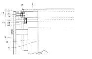
図3は、本実施形態に係るインクジェット捺染装置1の下流側の詳細を示した背面図、図4は本実施形態に係るインクジェット捺染装置1の下流側の詳細を示した側面図である。図3及び図4に示すように、捺染された布帛Cをエンドレスベルト2から剥離するため、下流側駆動ローラ3bの下流に剥離ローラ7が設置されている。剥離ローラ7は、軸部71とローラ本体部72とを有している。軸部71はローラ本体部72よりも長いため、ローラ本体部72の両端から軸部71の両端部が突出しており、その突出した軸部71の両端部が支持枠9に支持されている。この軸部71を中心に回転するように、ローラ本体部72が軸受73を介して軸部71に取り付けられている。このローラ本体部72は、布帛Cの種類に応じて取り換えることができ、例えば表面の材質がシリコンゴムや金属、塩化ビニルなどの種々のローラ本体部72を準備しておき、布帛Cに適したローラ本体部72を選択することができる。なお、この剥離ローラ7は、布帛Cとエンドレスベルト2とが剥離し始める部分に近い位置に設置されることが好ましく、前記剥離し始める位置から100mm以内であることが好ましい。
FIG. 3 is a rear view showing details on the downstream side of the ink
剥離ローラ7と下流側駆動ローラ3bとの間にカウンターローラ11が設置されている。カウンターローラ11は、軸部111と2つのローラ本体部112とを有している。軸部111は、支持枠9に両端部が支持されている。この軸部111を中心に回転するように、2つのローラ本体部112が軸受113を介して軸部111に取り付けられている。このローラ本体部112は、剥離ローラ7のローラ本体部102における両端部と対向する位置に取り付けられている。このカウンターローラ11は、下流側駆動ローラ3b及び剥離ローラ7に接触しているため、まず、下流側駆動ローラ3bによって図4の時計回りに回転する。この時計回りに回転するカウンターローラ11は、剥離ローラ7にも接触しているため、剥離ローラ7を図4の反時計回りに回転させる。カウンターローラ11のローラ本体部112の表面は、ウレタンゴムや、鋼、樹脂などによって形成することができる。
A
剥離ローラ7によってエンドレスベルト2から剥離された布帛Cを乾燥するよう、剥離ローラ7の下流に乾燥用ヒータープレート8が設置されている。捺染された布帛Cを乾燥するために、好ましくは乾燥用ヒータープレート8を100〜130度まで上昇する。そして、乾燥用ヒータープレート8の下流には、乾燥した布帛Cを巻き取るための巻取ローラC2が設置されている。
A drying
次に、上述したインクジェット捺染装置1による捺染方法について説明する。
Next, a printing method using the above-described
まず、図1に示すように、巻出しローラC1から巻出された布帛Cを、エンドレスベルト2と貼付ローラ4との間を通す。これにより、布帛Cは、貼付ローラ4の自重でエンドレスベルト2上に押圧されてエンドレスベルト2上に貼り付けられる。
First, as shown in FIG. 1, the fabric C unwound from the unwinding roller C <b> 1 is passed between the
このようにエンドレスベルト2上に貼り付けられた布帛Cは、エンドレスベルト2によって搬送されてインクジェット捺染ユニット6によって捺染を行われる。その後、布帛Cは、下流側駆動ローラ3bまで搬送され、剥離ローラ7によってエンドレスベルト2から剥離される。剥離された布帛Cは乾燥用ヒータプレート8によって乾燥された後、巻取ローラC2によって巻き取られる。
The fabric C thus affixed on the
以上、本実施形態によれば、剥離ローラ7によって、布帛Cをエンドレスベルト2から剥離しているため、布帛Cとエンドレスベルトとが剥離する部分の近くに剥離手段を設置することができる。このため、布帛Cを剥離する際に掛かる力を低減することができ、ひいては、薄地の布帛やニット製の布帛の品質を損なうことなく捺染することができる。
As described above, according to this embodiment, since the cloth C is peeled from the
以上、本発明の実施形態について説明したが、本発明はこれらに限定されるものではなく、本発明の趣旨を逸脱しない限りにおいて種々の変更が可能である。例えば、上記実施形態では、剥離ローラ7は軸部71とローラ本体部72とを別々にしているが、これらを一体的に構成することもできる。
As mentioned above, although embodiment of this invention was described, this invention is not limited to these, A various change is possible unless it deviates from the meaning of this invention. For example, in the above-described embodiment, the peeling
また、上記実施形態では、剥離ローラ7の駆動源を下流側駆動ローラ3bの駆動源と同じとしたが、特にこれに限定されるものではなく、例えば、剥離ローラ7の駆動源を下流側駆動ローラ3bの駆動源と別の駆動源を用いることができる。これにより、下流側駆動ローラ3bの回転速度と異なる回転速度とすることができる。
In the above embodiment, the driving source of the peeling
また、上記実施形態は、ヒータープレート8によって布帛Cを乾燥させているが、この他にも例えば熱風発生装置によって布帛Cを乾燥させてもよいし、これら両方を併用して布帛Cを乾燥させることもできる。
In the above embodiment, the fabric C is dried by the
1 インクジェット捺染装置
2 エンドレスベルト
3a 上流側駆動ローラ
3b 下流側駆動ローラ
7 剥離ローラ
C 布帛(被捺染物)
C1 巻取ローラ
DESCRIPTION OF
C1 Winding roller
Claims (6)
被捺染物が貼り付く粘着面を有し、被捺染物を上流から下流に搬送するエンドレスベルトと、
前記エンドレスベルトを駆動する上流側駆動ローラ及び下流側駆動ローラと、
前記下流側駆動ローラの下流に設置された、被捺染物を巻き取る巻取ローラと、
前記下流側駆動ローラと前記巻取ローラとの間に設置され、被捺染物をエンドレスベルトから剥離するよう回転駆動される剥離ローラと、
を備えた、インクジェット捺染装置。 An ink jet printing apparatus for printing an object to be printed,
An endless belt that has an adhesive surface to which the object to be printed is attached and conveys the object to be printed from upstream to downstream;
An upstream drive roller and a downstream drive roller for driving the endless belt;
A winding roller installed on the downstream side of the downstream drive roller, which winds up the printed material;
A peeling roller that is installed between the downstream drive roller and the winding roller, and is rotationally driven so as to peel the printed material from the endless belt;
An inkjet printing apparatus comprising:
Priority Applications (2)
| Application Number | Priority Date | Filing Date | Title |
|---|---|---|---|
| JP2008104046A JP5116543B2 (en) | 2008-04-11 | 2008-04-11 | Inkjet printing device |
| CN2009101312616A CN101554800B (en) | 2008-04-11 | 2009-04-10 | Ink-jet printing device |
Applications Claiming Priority (1)
| Application Number | Priority Date | Filing Date | Title |
|---|---|---|---|
| JP2008104046A JP5116543B2 (en) | 2008-04-11 | 2008-04-11 | Inkjet printing device |
Publications (2)
| Publication Number | Publication Date |
|---|---|
| JP2009256812A JP2009256812A (en) | 2009-11-05 |
| JP5116543B2 true JP5116543B2 (en) | 2013-01-09 |
Family
ID=41173150
Family Applications (1)
| Application Number | Title | Priority Date | Filing Date |
|---|---|---|---|
| JP2008104046A Active JP5116543B2 (en) | 2008-04-11 | 2008-04-11 | Inkjet printing device |
Country Status (2)
| Country | Link |
|---|---|
| JP (1) | JP5116543B2 (en) |
| CN (1) | CN101554800B (en) |
Families Citing this family (4)
| Publication number | Priority date | Publication date | Assignee | Title |
|---|---|---|---|---|
| JP6301156B2 (en) * | 2014-02-25 | 2018-03-28 | セーレン株式会社 | Recording device |
| JP6617542B2 (en) * | 2015-12-09 | 2019-12-11 | セイコーエプソン株式会社 | Liquid ejection device |
| CN106142839A (en) * | 2016-06-23 | 2016-11-23 | 合肥晖腾数控科技有限公司 | A kind of drawing processing device |
| EP4126556B1 (en) * | 2020-05-21 | 2024-08-14 | Hewlett-Packard Development Company, L.P. | Adhesive surfaces for printing devices |
Family Cites Families (4)
| Publication number | Priority date | Publication date | Assignee | Title |
|---|---|---|---|---|
| JPS5964378A (en) * | 1982-10-06 | 1984-04-12 | Asahi Screen Process Insatsu Kk | Printing paper holding mount sheet and printing method therefor |
| JPH05112037A (en) * | 1991-10-22 | 1993-05-07 | Nec Corp | Printer device |
| US6068374A (en) * | 1994-02-08 | 2000-05-30 | Canon Kabushiki Kaisha | Image forming apparatus |
| JPH07214767A (en) * | 1994-02-08 | 1995-08-15 | Canon Inc | Ink jet printer |
-
2008
- 2008-04-11 JP JP2008104046A patent/JP5116543B2/en active Active
-
2009
- 2009-04-10 CN CN2009101312616A patent/CN101554800B/en active Active
Also Published As
| Publication number | Publication date |
|---|---|
| CN101554800A (en) | 2009-10-14 |
| CN101554800B (en) | 2013-11-13 |
| JP2009256812A (en) | 2009-11-05 |
Similar Documents
| Publication | Publication Date | Title |
|---|---|---|
| JP5116542B2 (en) | Inkjet printing apparatus for fabric | |
| JP4064707B2 (en) | Method for conveying and cutting heat-sensitive adhesive sheet and printer for heat-sensitive adhesive sheet | |
| JP5546281B2 (en) | Label manufacturing apparatus and label printing machine | |
| KR101523041B1 (en) | method for making for label sticker having not release paper and label sticker having not release paper maked by this | |
| JP5531322B2 (en) | Media transport mechanism, printer apparatus, and media transport method | |
| JP2014094827A (en) | Conveyance device for base material and conveyance method for base material | |
| JP5116543B2 (en) | Inkjet printing device | |
| JP6314674B2 (en) | Image forming apparatus | |
| JP2012071589A (en) | Recording apparatus | |
| JP2004123386A (en) | Cloth printing system and cloth printing method | |
| JP6176016B2 (en) | Image forming apparatus | |
| JP2013199013A (en) | Recording device | |
| JP5275770B2 (en) | Sheet sticking device and sticking method | |
| EP2754560B1 (en) | Recording apparatus | |
| JP4736662B2 (en) | Image recording device | |
| JP5953970B2 (en) | Liquid ejector | |
| JP6466731B2 (en) | Inkjet printing device | |
| JP3146588U (en) | Inkjet printing device | |
| JP7122471B2 (en) | LABELING APPARATUS, CONTROLLING METHOD FOR LABELING APPARATUS, AND PROGRAM | |
| JP7404757B2 (en) | liquid discharge device | |
| JP2001058428A (en) | Printing apparatus | |
| JP5587717B2 (en) | Sheet sticking device and sticking method | |
| JP5863541B2 (en) | Printing apparatus and printing method | |
| JP6083155B2 (en) | Medium feeding device and recording device | |
| JP2891881B2 (en) | Printing labels, manufacturing and attaching method of printing labels, and manufacturing and applying apparatus of printing labels |
Legal Events
| Date | Code | Title | Description |
|---|---|---|---|
| A621 | Written request for application examination |
Free format text: JAPANESE INTERMEDIATE CODE: A621 Effective date: 20110208 |
|
| TRDD | Decision of grant or rejection written | ||
| A01 | Written decision to grant a patent or to grant a registration (utility model) |
Free format text: JAPANESE INTERMEDIATE CODE: A01 Effective date: 20120925 |
|
| A01 | Written decision to grant a patent or to grant a registration (utility model) |
Free format text: JAPANESE INTERMEDIATE CODE: A01 |
|
| A61 | First payment of annual fees (during grant procedure) |
Free format text: JAPANESE INTERMEDIATE CODE: A61 Effective date: 20121016 |
|
| R150 | Certificate of patent or registration of utility model |
Free format text: JAPANESE INTERMEDIATE CODE: R150 Ref document number: 5116543 Country of ref document: JP Free format text: JAPANESE INTERMEDIATE CODE: R150 |
|
| FPAY | Renewal fee payment (event date is renewal date of database) |
Free format text: PAYMENT UNTIL: 20151026 Year of fee payment: 3 |
|
| R250 | Receipt of annual fees |
Free format text: JAPANESE INTERMEDIATE CODE: R250 |
|
| S111 | Request for change of ownership or part of ownership |
Free format text: JAPANESE INTERMEDIATE CODE: R313113 |
|
| R350 | Written notification of registration of transfer |
Free format text: JAPANESE INTERMEDIATE CODE: R350 |
|
| R250 | Receipt of annual fees |
Free format text: JAPANESE INTERMEDIATE CODE: R250 |
|
| R250 | Receipt of annual fees |
Free format text: JAPANESE INTERMEDIATE CODE: R250 |
|
| R250 | Receipt of annual fees |
Free format text: JAPANESE INTERMEDIATE CODE: R250 |
|
| R250 | Receipt of annual fees |
Free format text: JAPANESE INTERMEDIATE CODE: R250 |
|
| R250 | Receipt of annual fees |
Free format text: JAPANESE INTERMEDIATE CODE: R250 |
|
| R250 | Receipt of annual fees |
Free format text: JAPANESE INTERMEDIATE CODE: R250 |
|
| R250 | Receipt of annual fees |
Free format text: JAPANESE INTERMEDIATE CODE: R250 |