JP5116521B2 - Container for liquid - Google Patents

Container for liquid Download PDF

Info

Publication number
JP5116521B2
JP5116521B2 JP2008065804A JP2008065804A JP5116521B2 JP 5116521 B2 JP5116521 B2 JP 5116521B2 JP 2008065804 A JP2008065804 A JP 2008065804A JP 2008065804 A JP2008065804 A JP 2008065804A JP 5116521 B2 JP5116521 B2 JP 5116521B2
Authority
JP
Japan
Prior art keywords
liquid
container
valve
partition
compartment
Prior art date
Legal status (The legal status is an assumption and is not a legal conclusion. Google has not performed a legal analysis and makes no representation as to the accuracy of the status listed.)
Active
Application number
JP2008065804A
Other languages
Japanese (ja)
Other versions
JP2009220843A (en
Inventor
能利 山口
浩司 松重
將之 相澤
歩 百々海
Current Assignee (The listed assignees may be inaccurate. Google has not performed a legal analysis and makes no representation or warranty as to the accuracy of the list.)
TOKUYMA DENTAL CORPORATION
Original Assignee
TOKUYMA DENTAL CORPORATION
Priority date (The priority date is an assumption and is not a legal conclusion. Google has not performed a legal analysis and makes no representation as to the accuracy of the date listed.)
Filing date
Publication date
Application filed by TOKUYMA DENTAL CORPORATION filed Critical TOKUYMA DENTAL CORPORATION
Priority to JP2008065804A priority Critical patent/JP5116521B2/en
Publication of JP2009220843A publication Critical patent/JP2009220843A/en
Application granted granted Critical
Publication of JP5116521B2 publication Critical patent/JP5116521B2/en
Active legal-status Critical Current
Anticipated expiration legal-status Critical

Links

Images

Description

本発明は、容器本体の開口に取付けられるノズル部と容器本体内との間に液体が通る隔室を形成した液体用容器に関する。   The present invention relates to a liquid container in which a compartment through which liquid passes is formed between a nozzle portion attached to an opening of a container body and the inside of the container body.

歯科用接着剤や各種治療薬等の種々の液体を充填する容器として、容器本体部とノズルとからなる液体用容器が用いられる。このような液体用容器は、容器本体部の可撓性を有する胴部(外周部)を指先で圧縮することにより、容器本体内に充填された液体を、ノズルの先端に設けられた液体流出口より少量ずつ流出させることができる。そして、容器本体を必要角度に傾倒させて使用することにより、液体を目的箇所に所望量だけ塗布や滴下させることができる。
しかしながら、冷蔵庫などに貯蔵していた液体用容器を、使用した後にそのまま室温で放置をしておくと、容器本体の内部の温度が室温の上昇するにつれて、容器本体の空気が膨張して、ノズルの内部に残っている液体をノズルの先端部から噴き出してしまい、それが液垂れとなってノズルの先端に付着することがある。
As a container for filling various liquids such as a dental adhesive and various therapeutic agents, a liquid container including a container main body and a nozzle is used. Such a container for liquid compresses the flexible body part (outer peripheral part) of the container main body part with a fingertip so that the liquid filled in the container main body flows into the liquid flow provided at the tip of the nozzle. A small amount can be discharged from the outlet. Then, by using the container body tilted to the required angle, the liquid can be applied or dripped in a desired amount to the target location.
However, if the liquid container stored in a refrigerator or the like is left at room temperature after use, the air in the container body expands as the temperature inside the container body rises, and the nozzle The liquid remaining in the inside of the nozzle may be ejected from the tip of the nozzle, and it may drip and adhere to the tip of the nozzle.

この噴き出し現象を防止するため、図7に示す液体用容器が下記の特許文献1として開示されている。
特許文献1の液体用容器51は、容器本体とノズル蓋部とを備え、容器本体は可撓性を有し、指先で胴部52を狭持して押圧し容器本体を圧縮することができる。また、容器本体の開口部に口頸部54が形成されており、その開口部にノズル蓋部が差し込まれている。ノズル蓋部には、液体流出口55が開口する突出部56が設けられ、液体流出口55と胴部内空部57とは、液体流通路58により連通している。
小口径の液体流通路58は、容器本体側の端部で拡径させた隔室60が形成されている。この隔室60には、復動部材61を遊嵌している。復動部材61は、その上面および側壁に、該復動部材が隔室60内を上昇して上面が隔室60の上壁に当接した際に、隔室60とこれより上方の液体流通路58とが連通するように液体流通用溝63が形成されている。
In order to prevent this ejection phenomenon, the liquid container shown in FIG.
The liquid container 51 of Patent Document 1 includes a container main body and a nozzle lid, and the container main body has flexibility, and can compress the container main body by holding and pressing the trunk portion 52 with a fingertip. . Further, a mouth / neck portion 54 is formed in the opening of the container body, and a nozzle lid portion is inserted into the opening. The nozzle lid portion is provided with a protruding portion 56 in which the liquid outlet 55 is opened, and the liquid outlet 55 and the body inner space 57 are communicated with each other through a liquid outlet passage 58.
The small-diameter liquid flow passage 58 is formed with a compartment 60 whose diameter is increased at the end on the container body side. A return movement member 61 is loosely fitted in the compartment 60. The reciprocating member 61 is arranged on the upper surface and side walls of the reciprocating member 61 when the reciprocating member ascends in the compartment 60 and the upper surface contacts the upper wall of the compartment 60. A liquid circulation groove 63 is formed so as to communicate with the channel 58.

このような構造の液体用容器51は、胴部52が押圧されると、胴部内空部57に充填される液体53は液体流通路58内に流入し上方に流れる。このとき、液体53は、液体流通下方路59と支持棒部62との間隙を流れる。
復動部材61は、液体53の液圧に押されて上面が隔室60の上壁に当接するが、隔室60と液体流通路58とが連通するように液体流通用溝63が形成されているため、この液体流通用溝63を通って、液体流通路58に流入し、胴部52の押圧の程度に応じて、液体流出口55から所望量の液体53を流出させることができる。
In the liquid container 51 having such a structure, when the barrel portion 52 is pressed, the liquid 53 filled in the barrel internal space 57 flows into the liquid flow path 58 and flows upward. At this time, the liquid 53 flows through the gap between the liquid flow downward path 59 and the support rod portion 62.
The return member 61 is pressed by the liquid pressure of the liquid 53 and has an upper surface that contacts the upper wall of the compartment 60, but a liquid circulation groove 63 is formed so that the compartment 60 and the liquid flow passage 58 communicate with each other. Therefore, a desired amount of the liquid 53 can be flowed out from the liquid outlet 55 according to the degree of pressing of the trunk portion 52 through the liquid circulation groove 63 and into the liquid flow passage 58.

液体53の注入後は、液体充填用容器51において、胴部52の押圧を弱め液体の流出のため傾倒させていた容器51を垂直に立てようとすると、隔室60内において、上壁に当接していた復動部材61は、すぐに下降を始める。この復動部材61の下降により、隔室60内に溜まっていた液体のほとんどは、液体流通下方路59に押し戻され、この際、上方の液体流通路58内に存在する液体53も、下方に流下する。その結果、使用直後において容器51の液ダレの発生が防止される。
特開2005−138990号公報
After the liquid 53 is injected, if the container 51 that has been tilted for the outflow of the liquid is weakened in the liquid filling container 51 and is tilted for the outflow of the liquid, The returning member 61 that has been in contact starts to descend immediately. Due to the descent of the return member 61, most of the liquid accumulated in the compartment 60 is pushed back to the liquid flow downward path 59. At this time, the liquid 53 existing in the upper liquid flow path 58 is also moved downward. Flow down. As a result, the occurrence of liquid dripping in the container 51 is prevented immediately after use.
JP 2005-138990 A

特許文献1の技術によると、上述のように液ダレが防止されるが、復動部材の移動によって、液体を胴部内空部に戻すようにしているので、使用後に容器に蓋を被せるようなときに、容器を立てる姿勢にすることなく、特に容器を横向きや下向きにした状態で蓋を被せて、そのまま容器を横置きにして保管したような場合は、復動部材の移動がなくその役割を果たすことができず、液ダレを生じることがある。
本発明は、このような事情に鑑みてなされたものであって、容器の姿勢に影響されることなく、液ダレを防止することのできる液体用容器を提供することにある。
According to the technique of Patent Document 1, liquid dripping is prevented as described above, but since the liquid is returned to the inner space of the body portion by the movement of the return member, the container is covered with a lid after use. Sometimes, when the container is placed in a horizontal or downward position without being placed in a standing position, and the container is stored in a horizontal position as it is, the return member does not move and its role Cannot be achieved, and dripping may occur.
This invention is made in view of such a situation, Comprising: It is providing the container for liquids which can prevent liquid dripping, without being influenced by the attitude | position of a container.

本発明の液体用容器は、上記目的を達成するために、胴部が可撓性を有する容器本体と該容器本体の開口部に取付けられるノズル蓋部とを備え、該ノズル蓋部には前記開口部に配設される筒状部と前記容器本体の開口部よりも外側に突出するノズル部とを備え、前記筒状部又は前記容器本体に該筒状部と前記容器本体内の液体収容室とを仕切る隔壁を設けることによって、前記ノズル部と前記液体収容室との間に隔室を形成した液体用容器において、前記隔壁には、前記液体収容室の内方側への押圧時に前記液体収容室の内圧力によって開弁し前記液体収容室側から前記隔室側に液体の流れを許容し、前記液体収容室への押圧力の解除時に前記液体収容室の減圧力によって開弁し前記隔室側から前記液体収容室への液体の流れを許容する切れ目を形成した隔壁弁を設け、前記隔室には、重力によって該隔室内を移動する移動弁を配設し、該移動弁の一端には前記容器本体の傾倒時に前記ノズル部の液体流通路における前記隔室側の一端を閉塞して液体の流通量を制限する規制部を形成し、前記移動弁の一端が前記ノズル部の液体流通路側に位置し、他端が前記隔壁側に位置するように前記移動弁と前記隔室とを形成し、該規制部には前記移動弁の前記液体流通路の閉塞時に、前記隔室と前記流通路とを連通する溝を形成した
上記液体用容器は、前記移動弁の他端側端部に前記容器本体の径方向に延びる溝を形成することができる。
上記液体用容器は、前記隔壁に該隔壁の周囲から立ち上がる周壁部を形成し、該周壁部の内周面によって前記筒状部の外周部を覆うようにすることができる。
In order to achieve the above object, the liquid container of the present invention comprises a container main body having a flexible body and a nozzle lid attached to an opening of the container main body. A cylindrical portion disposed in the opening and a nozzle portion protruding outward from the opening of the container main body, and the cylindrical portion or the container main body contains the liquid in the cylindrical portion and the container main body. In the liquid container in which a partition is formed between the nozzle part and the liquid storage chamber by providing a partition partitioning the chamber, the partition includes the partition when the inner side of the liquid storage chamber is pressed. The valve is opened by the internal pressure of the liquid storage chamber to allow the flow of the liquid from the liquid storage chamber side to the compartment side, and is opened by the decompression force of the liquid storage chamber when the pressing force to the liquid storage chamber is released. A slit that allows the flow of liquid from the compartment side to the liquid storage chamber. The septum valve formed with provided, said compartment, the moving valve to move the partition chamber by gravity disposed, at one end of the moving valve in the liquid flow path of the nozzle portion during tilting of the container body A restriction part that restricts one end of the compartment side to restrict the amount of liquid flow is formed, and one end of the moving valve is located on the liquid flow path side of the nozzle part, and the other end is located on the partition side. The transfer valve and the compartment are formed, and a groove is formed in the restricting portion to connect the compartment and the flow passage when the liquid flow passage of the movement valve is closed .
In the liquid container, a groove extending in the radial direction of the container main body can be formed at the other end of the transfer valve.
In the liquid container, a peripheral wall portion rising from the periphery of the partition wall may be formed on the partition wall, and an outer peripheral portion of the cylindrical portion may be covered with an inner peripheral surface of the peripheral wall portion.

本発明の液体用容器は、前記隔壁には、前記液体収容室の内方側への押圧時に前記液体収容室の内圧力によって開弁し前記液体収容室側から前記隔室側に液体の流れを許容し、前記液体収容室への押圧力の解除時に前記液体収容室の減圧力によって開弁し前記隔室側から前記液体収容室への液体の流れを許容する切れ目を形成した隔壁弁を設け、前記隔室には、重力によって該隔室内を移動する移動弁を配設し、該移動弁の一端には前記容器本体の傾倒時に前記ノズル部の液体流通路における前記隔室側の一端を閉塞して液体の流通量を制限する規制部を形成し、前記移動弁の一端が前記ノズル部の液体流通路側に位置し、他端が前記隔壁側に位置するように前記移動弁と前記隔室とを形成し、該規制部には前記移動弁の前記液体流通路の閉塞時に、前記隔室と前記流通路とを連通する溝を形成したので、ノズルの液体流通路に充填されている液体を容器本体側に戻すことができる。その結果、容器の姿勢に影響されることなく、液ダレを良好に防止できる。また、溝の大きさを適宜変更することによって、容器本体内の液体の粘度に合わせて液体の流通量を調整することができる。
上記液体用容器は、前記移動弁の他端側端部に前記容器本体の径方向に延びる溝を形成したので、移動弁が隔壁弁を塞ぐようなことがあっても、隔壁弁の開弁時に液体の流通を確保することができる。
上記液体用容器は、前記隔壁に該隔壁の周囲から立ち上がる周壁部を形成し、該周壁部の内周面によって前記筒状部の外周部を覆うようにしたので、仕切材の取付け容易になる。
In the liquid container according to the present invention, when the partition wall is pressed toward the inner side of the liquid storage chamber, the valve is opened by the internal pressure of the liquid storage chamber, and the liquid flows from the liquid storage chamber side to the partition side. A partition valve that is opened by the decompression force of the liquid storage chamber when the pressing force to the liquid storage chamber is released, and that forms a cut that allows the flow of liquid from the compartment side to the liquid storage chamber. A moving valve that moves in the compartment by gravity is provided in the compartment, and one end of the moving valve on one side of the compartment in the liquid flow passage of the nozzle portion when the container body is tilted. A restricting portion that restricts the flow rate of the liquid by closing the moving valve and the moving valve so that one end of the moving valve is located on the liquid flow path side of the nozzle portion and the other end is located on the partition wall side. Forming a compartment and closing the liquid flow passage of the transfer valve in the restricting portion. Sometimes, since a groove for communicating the flow passage with said compartment, the liquid filled in the liquid flow path of the nozzle can be returned to the container body side. As a result, dripping can be satisfactorily prevented without being affected by the attitude of the container. In addition, by appropriately changing the size of the groove, it is possible to adjust the flow rate of the liquid according to the viscosity of the liquid in the container body.
In the liquid container, a groove extending in the radial direction of the container main body is formed at the other end of the transfer valve. Therefore, even if the transfer valve may block the partition valve, the valve of the partition valve is opened. Sometimes the flow of liquid can be ensured.
In the liquid container, a peripheral wall portion rising from the periphery of the partition wall is formed on the partition wall, and the outer peripheral portion of the cylindrical portion is covered by the inner peripheral surface of the peripheral wall portion, so that the partition member can be easily attached. .

以下、本発明の第1の実施形態の液体用容器について、図面を参照しながら説明する。
図1は、本発明に係る液体用容器を示す。液体用容器1は、液体が充填される容器本体2と容器本体2の口頸部9の上端部に形成された開口部3に装着されるノズル蓋部5とを備えている。
容器本体2は、胴部が手で挟持して圧縮できる程度の可撓性を備えるものであれは制限なく採択できる。一般には、ポリエチレン、ポリプロピレン等のポリオレフィン;ポリアセタール;アクリロニトリル―ブタジエン―スチレン樹脂(ABS樹脂)などの合成樹脂が好ましい。また、遮光性、ガスバリア性を持たせたポリエチレン−ABS−ポリエチレン等の3層構造を有する材質で容器を形成しても良い。上記樹脂で形成された容器本体2は、上部に肩部4を形成し、肩部4よりも下部は円筒状の胴部7を形成し、胴部7の下端に円形の底部8を形成している。この可撓性の容器本体2は、胴部7を指先で挟み込むようにして押すと、押圧力によって胴部7が内側に窪み、指先を離すともとの形状に戻るような弾性力を有する。
Hereinafter, a liquid container according to a first embodiment of the present invention will be described with reference to the drawings.
FIG. 1 shows a liquid container according to the present invention. The liquid container 1 includes a container body 2 that is filled with a liquid and a nozzle lid portion 5 that is attached to an opening 3 formed at the upper end of the mouth / neck portion 9 of the container body 2.
The container body 2 can be adopted without limitation as long as the body is flexible enough to be sandwiched and compressed by hand. In general, polyolefins such as polyethylene and polypropylene; polyacetals; and synthetic resins such as acrylonitrile-butadiene-styrene resin (ABS resin) are preferable. Further, the container may be formed of a material having a three-layer structure such as polyethylene-ABS-polyethylene having light shielding properties and gas barrier properties. The container body 2 made of the above resin forms a shoulder portion 4 at the top, a cylindrical body portion 7 below the shoulder portion 4, and a circular bottom portion 8 at the lower end of the body portion 7. ing. The flexible container body 2 has an elastic force such that when the body part 7 is pushed so as to be sandwiched between the fingertips, the body part 7 is depressed inward by the pressing force and returns to the original shape when the fingertip is released.

ノズル蓋部5も、上記容器本体2と同様の材料(合成樹脂)で形成されるが、液切れ性を向上させる観点からは、フッ素系樹脂を使用するのも好ましい態様である。また、液体の滴下位置の正確性を高める観点からは実質的に変形をしない剛性のものとするのが好ましいため、ノズル蓋部5の壁の厚さは、該容器本体2よりも厚くするのが好適である。このノズル蓋部5は、一体成形により形成され、基端側に断面が円形の筒状部10が形成され、先端側にノズル11が形成され、これらの筒状部10とノズル11の間にフランジ部12が形成されている。   The nozzle lid portion 5 is also formed of the same material (synthetic resin) as that of the container body 2, but it is also a preferable aspect to use a fluorine-based resin from the viewpoint of improving the liquid breakage. In addition, from the viewpoint of improving the accuracy of the liquid dripping position, it is preferable to have a rigidity that does not substantially deform, so that the wall thickness of the nozzle lid portion 5 is made thicker than the container body 2. Is preferred. The nozzle lid portion 5 is formed by integral molding, a cylindrical portion 10 having a circular cross section is formed on the proximal end side, a nozzle 11 is formed on the distal end side, and between the cylindrical portion 10 and the nozzle 11. A flange portion 12 is formed.

フランジ部12は、筒状部10の上端縁から筒状部10の半径方向外側に突出する環状部であり、開口部3よりも大きな径を有し、フランジ部12と筒状部10の上端部を密着させることによって、ノズル蓋部5と容器本体2との境界部が気密になるようにシール性を維持させることができる。
ノズル11は、先細りのテーパー形状であって、軸方向に小径の流通路14がノズル11の中央位置を貫通し、流通路14の先端部には先端部に向かって徐々に拡径する注出口15が設けられている。流通路14の径は、通常状態で液体の毛細管現象が起きるような径に形成されている。
筒状部10には、図2に示すように、ほぼ円筒有底形状の仕切材16が取付けられている。仕切材16は、弾性を有する部材を用いる。こうした弾性を有する部材としては、具体的には、隔壁弁19の進退移動のし易さの観点から、JIS6253記載の硬さ試験方法に準拠した方法で測定した硬さが30〜100(国際ゴム硬さ:IRHD)、より好ましくは40〜80(IRDH)である合成ゴムや、エラストマー樹脂などが好適である。
The flange portion 12 is an annular portion that protrudes radially outward from the upper end edge of the tubular portion 10, has a larger diameter than the opening portion 3, and has upper ends of the flange portion 12 and the tubular portion 10. By bringing the portions into close contact with each other, the sealing performance can be maintained so that the boundary portion between the nozzle lid portion 5 and the container body 2 becomes airtight.
The nozzle 11 has a tapered shape with a small-diameter flow passage 14 passing through the central position of the nozzle 11 in the axial direction, and a spout that gradually increases in diameter toward the tip at the tip of the flow passage 14. 15 is provided. The diameter of the flow passage 14 is formed such that a liquid capillary phenomenon occurs in a normal state.
As shown in FIG. 2, a substantially cylindrical bottomed partition member 16 is attached to the tubular portion 10. As the partition member 16, an elastic member is used. Specifically, the elastic member has a hardness measured by a method based on a hardness test method described in JIS 6253 from the viewpoint of easy advancement and retraction of the bulkhead valve 19 (international rubber). Hardness: IRHD), more preferably 40-80 (IRDH) synthetic rubber, elastomer resin, etc. are suitable.

仕切材16は、周壁部17と底部からなる円形の隔壁18とからなり、周壁部17は、筒状部10の周囲を包むように、内径を筒状部10の外周径とほぼ同じで、そのまま或いは弾性力で筒状部10の周囲に取付けられる程度の大きさに形成している。仕切材16の隔壁18は、筒状部10の下端部開口に対応する位置に配置され、容器本体2の内部に設けられた液体収容室6とノズル蓋部5との間を仕切っている。隔壁18の中心部には、直線状の切れ目を形成した隔壁弁19が形成されている。
隔壁弁19を開閉弁として有効に機能させるには、隔壁弁19の近傍はその周りよりも少し薄くするのが、容器本体2の胴部7を押して容器本体2の内部圧力を上昇させた時に該隔壁弁19が開弁しやすくなり、液の出入りが容易になり、液の滴下性能を向上させることができるため好適である。
The partition member 16 includes a peripheral wall portion 17 and a circular partition wall 18 including a bottom portion. The peripheral wall portion 17 has an inner diameter that is substantially the same as the outer peripheral diameter of the cylindrical portion 10 so as to wrap around the cylindrical portion 10. Alternatively, it is formed in a size that can be attached to the periphery of the tubular portion 10 by elastic force. The partition wall 18 of the partition member 16 is disposed at a position corresponding to the lower end opening of the cylindrical portion 10, and partitions between the liquid storage chamber 6 provided in the container body 2 and the nozzle lid portion 5. A partition valve 19 having a straight cut is formed at the center of the partition wall 18.
In order for the bulkhead valve 19 to function effectively as an on-off valve, the vicinity of the bulkhead valve 19 is made slightly thinner than the surrounding area when the internal pressure of the container body 2 is increased by pushing the body portion 7 of the container body 2. The partition valve 19 is easy to open, and it is preferable because the liquid can easily enter and exit, and the dropping performance of the liquid can be improved.

容器本体2に外力が負荷されていない状態(以下、無負荷状態という)では、隔壁弁19は閉弁状態にあり、容器本体2の胴部7を押圧して液体収容室6に内圧を負荷すると、仕切材16の隔壁18がノズル蓋部5の先端側に押圧され、隔壁弁19の切れ目が拡がり、開弁状態になる。そして、再び無負荷状態にすると、胴部7がもとの初期形状に戻り、内圧が減少して、隔壁弁19の切れ目がもとの状態に戻る。このように、隔壁18は容器本体2の内圧に依存して、隔壁弁19の切れ目が開閉弁となって容器本体2内の液体の流通を許容する。
仕切材16の周壁部17は、内周側にノズル蓋部5の筒状部10の底部を隔壁18が覆うように嵌入し、周壁部17の開口側の上端部はフランジ部12に当接させている。仕切材16は、筒状部10に装着された状態で、容器本体2の口頸部9の内部に装着される。
液体用容器1には、上述の隔壁18とノズル蓋部5の筒状部10及びノズル11の下部壁21によって区画されている隔室22が形成されている。隔室22は、流通路14と連通し、隔室22の容積は、流通路14よりも十分に大きく、容器本体2の内部空間よりも小さく形成されている。ノズル11の下部壁21は、上方側が減径するテーパー形状の絞り面21が形成されている。
In a state where no external force is applied to the container body 2 (hereinafter referred to as an unloaded state), the partition valve 19 is in a closed state, and the body 7 of the container body 2 is pressed to apply an internal pressure to the liquid storage chamber 6. Then, the partition wall 18 of the partitioning member 16 is pressed toward the tip end side of the nozzle lid portion 5, and the break of the partition valve 19 is expanded to be in a valve open state. When the no-load state is set again, the body portion 7 returns to the original initial shape, the internal pressure decreases, and the cut of the partition valve 19 returns to the original state. Thus, depending on the internal pressure of the container body 2, the partition wall 18 allows the liquid in the container body 2 to flow as the opening of the partition valve 19 becomes an on-off valve.
The peripheral wall portion 17 of the partition member 16 is fitted on the inner peripheral side so that the partition wall 18 covers the bottom of the cylindrical portion 10 of the nozzle lid portion 5, and the upper end portion on the opening side of the peripheral wall portion 17 abuts on the flange portion 12. I am letting. The partition member 16 is attached to the inside of the mouth / neck portion 9 of the container body 2 in a state where the partition member 16 is attached to the cylindrical portion 10.
The liquid container 1 is formed with a compartment 22 defined by the partition wall 18, the cylindrical portion 10 of the nozzle lid portion 5, and the lower wall 21 of the nozzle 11. The compartment 22 communicates with the flow passage 14, and the volume of the compartment 22 is sufficiently larger than the flow passage 14 and smaller than the internal space of the container body 2. The lower wall 21 of the nozzle 11 is formed with a tapered diaphragm surface 21 whose upper side is reduced in diameter.

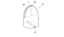
図4に示すように、隔室22には、移動弁23が収容されている。移動弁23の材質は、特に問わないが、加工をしやすいように、本実施形態では合成樹脂製としている。ただし、容器本体2に入れられる液体の比重よりも大きなものを用いる必要がある。
移動弁23の形状は、一端(容器の正立姿勢で上端)がほぼ半球形であり、他端(同じく下端)が円柱形のいわゆる弾丸形状である。一端側には、一対の扇状溝24a,24bを形成し、これらの扇状溝24a,24bは同一直径状に先端部(又は中心部)Pを挟むようにした位置に形成されている。
一方の扇状溝24aは、移動弁23の中心部Pを僅かにずれた部位から、移動弁23の軸方向他端側へ向かい、該移動弁23のほぼ上下方向中間位置で、半径方向外側に向かって薄く切り欠くようにして開角がほぼ90度の扇状になるように形成している。
As shown in FIG. 4, a movement valve 23 is accommodated in the compartment 22. The material of the moving valve 23 is not particularly limited, but is made of a synthetic resin in the present embodiment so as to be easily processed. However, it is necessary to use a liquid having a larger specific gravity than the liquid put in the container body 2.
The shape of the moving valve 23 is a so-called bullet shape in which one end (upper end in the upright posture of the container) is substantially hemispherical and the other end (also lower end) is cylindrical. A pair of fan-shaped grooves 24a and 24b is formed on one end side, and these fan-shaped grooves 24a and 24b are formed at positions where the tip portion (or center portion) P is sandwiched with the same diameter.
One fan-shaped groove 24a is directed from the portion slightly displaced from the central portion P of the moving valve 23 toward the other axial end of the moving valve 23, and is radially outward at a substantially vertical intermediate position of the moving valve 23. It is formed in a fan shape with an opening angle of approximately 90 degrees so as to be cut out thinly.

移動弁23の底面部には、長溝25を形成している。長溝25は、移動弁23の径方向の一端から他端まで貫通する直線状かつ一条の溝であり、径方向に向かって形成された扇状溝24a,24bの延在方向に対して周方向に90度ずらした方向に形成されている。したがって、移動弁23を平面視で見ると溝24a,24b,25は十字形状となる。
移動弁23と隔室22との関係は、移動弁23が倒れようとしても、移動弁23が水平方向へ向いて傾倒しないようにする必要がある。したがって、隔室22の形状が円筒形であれば、移動弁の高さHと隔室22の径Dの関係は、H>Dを満たすようにする。こうすれば、常に移動弁23の先端部である半球形の側が常に流通路14側に向くようになる。
なお、この液体用容器1の筒状の口頸部9の外周囲には、雄ネジ26が形成され、ノズル蓋部5に被せる図示しないキャップが装着されるが、図面では省略されている。また、液体用容器2に入れられる液体は、水、薬品、接着剤などの液状のものである。
A long groove 25 is formed on the bottom surface of the moving valve 23. The long groove 25 is a straight and single groove that penetrates from one end to the other end of the moving valve 23 in the radial direction, and is circumferential in the extending direction of the fan-shaped grooves 24a and 24b formed in the radial direction. It is formed in a direction shifted by 90 degrees. Accordingly, when the moving valve 23 is viewed in plan view, the grooves 24a, 24b, and 25 have a cross shape.
The relationship between the movement valve 23 and the compartment 22 needs to prevent the movement valve 23 from tilting in the horizontal direction even if the movement valve 23 is about to fall down. Therefore, if the shape of the compartment 22 is cylindrical, the relationship between the height H of the moving valve and the diameter D of the compartment 22 satisfies H> D. In this way, the hemispherical side, which is the tip of the moving valve 23, always faces the flow passage 14 side.
Note that a male screw 26 is formed around the outer periphery of the cylindrical mouth-neck portion 9 of the liquid container 1 and a cap (not shown) that covers the nozzle lid portion 5 is attached, but is omitted in the drawing. The liquid put in the liquid container 2 is liquid such as water, chemicals, and adhesive.

次に、本実施形態における液体用容器の作用について説明する。
この液体用容器1を使用するときは、図示しないキャップを外し、図3に示すように、液体用容器1の上下を反対にしてノズル11の注出口15が下向きになるように傾倒させて使用する。容器本体2は、実質的に容器本体2を把持するのみで胴部7を押していない状態では、隔室22側と容器本体2の液体収容室6側との圧力の均衡がとれている。液体を排出するには、容器本体2の胴部7を軽く圧迫するように指先で押圧する。
通常時では、隔壁弁19は閉弁状態にあるので、容器本体2の内部空間である液体収容室6の内部圧力が上昇し、隔壁弁19が開弁する。隔壁弁19が開弁することによって、液体収容室6側から隔室18側への液体の流通を可能にする。一方、移動弁23は、容器本体2を傾倒させているので、重力作用でノズル蓋部5の流通路14に先端部Pを当接させる。この際、下部壁21は移動弁23の先端部Pを流通路14に案内する。移動弁23の一端には、一対の扇状溝24a,24bを形成しているので、液体は流通することができる。
Next, the operation of the liquid container in the present embodiment will be described.
When the liquid container 1 is used, the cap (not shown) is removed, and the liquid container 1 is tilted so that the spout 15 of the nozzle 11 faces downward with the liquid container 1 upside down as shown in FIG. To do. In the state where the container main body 2 substantially grips the container main body 2 and does not push the body portion 7, the pressure balance between the compartment 22 side and the liquid storage chamber 6 side of the container main body 2 is balanced. In order to discharge the liquid, the body 7 of the container body 2 is pressed with a fingertip so as to lightly press.
Under normal conditions, the partition valve 19 is in a closed state, so that the internal pressure of the liquid storage chamber 6 that is the internal space of the container body 2 rises and the partition valve 19 is opened. By opening the partition valve 19, the liquid can be circulated from the liquid storage chamber 6 side to the compartment 18 side. On the other hand, since the moving valve 23 tilts the container body 2, the tip P is brought into contact with the flow passage 14 of the nozzle lid portion 5 by a gravitational action. At this time, the lower wall 21 guides the distal end portion P of the moving valve 23 to the flow passage 14. Since a pair of fan-shaped grooves 24a and 24b are formed at one end of the moving valve 23, the liquid can circulate.

こうして、液体は、液体収容室6側から隔壁弁19の切れ目を通って、隔室22,移動弁23の扇状溝24a,24bを通って流通路14、注出口15に排出される。この際、液体が注出口15にて滴になったときに、指先で押圧力を調整しながら、必要滴数だけ所望部分に、液体などを滴下することができる。
隔室22と液体収容室6との間には、隔壁弁19を有するので、液体収容室6の内圧よりも隔室22の内圧は小さいので、液体が容器本体2の押圧する容積に比べて、液体の排出量は少ないので、微調整が可能になる。
In this way, the liquid is discharged from the liquid storage chamber 6 side through the partition valve 19, through the compartment 22 and the fan-shaped grooves 24 a and 24 b of the transfer valve 23, and into the flow passage 14 and the spout 15. At this time, when the liquid becomes droplets at the spout 15, the liquid or the like can be dropped onto the desired portion by the required number of droplets while adjusting the pressing force with the fingertip.
Since the partition valve 19 is provided between the compartment 22 and the liquid storage chamber 6, the internal pressure of the compartment 22 is smaller than the internal pressure of the liquid storage chamber 6, so that the liquid is compared with the volume pressed by the container body 2. Because the amount of liquid discharged is small, fine adjustment is possible.

本実施形態の液体用容器1は、特に粘度の小さな液体を使用するときに好適である。すなわち、粘度の小さな液体では、容器本体を押圧するとそれに敏感に応答し、排出口から液体が勢いよく飛び出す傾向にある。本実施形態では、隔壁弁19の閉塞力によって、容器本体2の押圧時における液体収容室6に直接負荷する内圧を、隔室22が間接的に負荷するようにし、内圧力に対する隔室22の応答性を鈍らせ、液体の排出量の微調整が可能になる。さらに移動弁23の存在によって、液体を注出口15から滴状に排出させる液切れ性を向上させることができ、扇状溝24a,24bの大きさを適宜調整すれば、液体の粘度に適合させた液切れ性の微調整が可能になる。
なお、この隔壁弁19は、容器本体2の押圧の初期には、すぐに開弁せず、液体収容室6内の内圧がある程度上昇してから開弁するため、係る押圧の初期において、内圧の高まり具合が激しかった場合には、開弁と同時に上記低粘度の液体が一気に隔室22に流入する危険性がある。しかしながら、本実施形態によれば、このような押圧の初期にも、移動弁23の存在によって、ノズル蓋部5の流通路14は閉塞されており。上記隔室22に流入した液体は扇状溝24a,24bにより規制された量しか流通路14には流れないため、上記隔室22に流入した低粘度の液体も、注出口15から飛び出すような虞がない。
The liquid container 1 of the present embodiment is particularly suitable when a liquid having a low viscosity is used. That is, in the case of a liquid having a low viscosity, when the container body is pressed, it responds sensitively, and the liquid tends to jump out of the outlet. In the present embodiment, due to the closing force of the partition valve 19, the compartment 22 is indirectly loaded with the internal pressure directly applied to the liquid storage chamber 6 when the container body 2 is pressed, and the compartment 22 against the internal pressure is loaded. The response is dulled and the liquid discharge can be finely adjusted. Furthermore, the presence of the transfer valve 23 can improve the liquid breakage of discharging the liquid from the spout 15 in the form of droplets, and if the sizes of the fan-shaped grooves 24a and 24b are appropriately adjusted, the liquid can be adapted to the viscosity. Fine adjustment of the drainage is possible.
The partition valve 19 does not immediately open when the container main body 2 is pressed, and opens after the internal pressure in the liquid storage chamber 6 has increased to some extent. When the degree of increase in the pressure is severe, there is a risk that the low-viscosity liquid may flow into the compartment 22 at the same time as the valve is opened. However, according to the present embodiment, the flow passage 14 of the nozzle lid 5 is blocked by the presence of the moving valve 23 even at the initial stage of such pressing. Since the liquid flowing into the compartment 22 flows through the flow passage 14 only in an amount regulated by the fan-shaped grooves 24 a and 24 b, the low-viscosity liquid that has flowed into the compartment 22 may jump out of the spout 15. There is no.

液体の滴下作業が終了した状態では、指先の押圧力を解除することにより液体収容室6の内圧が下がる。このとき、ノズル11の流通路14の内部に残った液体を隔室22に引き戻すことができる。例えば、液体を排出しようとして、そのまま液体を吐出することなく、もとに戻したような場合にも、液体収容室6の容積の変動量に比べ、ノズル11の流通路14の容積が小さいため、流通路14の液体を隔室22及び液体収容室6に戻すことができる。その結果、ノズル11からの液ダレを良好に防止できる。
なお、容器本体2を傾倒させた状態から起立姿勢に戻したときは、移動弁23が隔壁18の隔壁弁19に当接するが、移動弁23の底部には長溝25を形成しているため、液体若しくは空気の流通ができる。そして、容器本体2の胴部7が弾性体の復元力によってもとの円筒形状に戻り、隔室22内の液体が容器本体2の内部に流入する。同時に、容器本体2側から吐出された液体の容積分を補う量の空気が液体収容室6に流入する。容器本体2の内部圧力がもとに戻ると、隔壁18の隔壁弁19が閉じる。
In the state where the liquid dropping operation is completed, the internal pressure of the liquid storage chamber 6 is reduced by releasing the pressing force of the fingertip. At this time, the liquid remaining inside the flow passage 14 of the nozzle 11 can be drawn back to the compartment 22. For example, even when the liquid is discharged without being discharged as it is, the volume of the flow passage 14 of the nozzle 11 is smaller than the amount of change in the volume of the liquid storage chamber 6. The liquid in the flow passage 14 can be returned to the compartment 22 and the liquid storage chamber 6. As a result, dripping from the nozzle 11 can be satisfactorily prevented.
When the container body 2 is returned from the tilted state to the standing posture, the movement valve 23 comes into contact with the partition valve 19 of the partition wall 18, but a long groove 25 is formed at the bottom of the movement valve 23. Liquid or air can be circulated. And the trunk | drum 7 of the container main body 2 returns to the original cylindrical shape by the restoring force of an elastic body, and the liquid in the compartment 22 flows in into the container main body 2. FIG. At the same time, an amount of air that supplements the volume of the liquid discharged from the container body 2 side flows into the liquid storage chamber 6. When the internal pressure of the container body 2 is restored, the partition valve 19 of the partition wall 18 is closed.

本実施形態の液体用容器1は、隔壁弁19の切れ目の開弁作用と液体収容室6の減圧力により、液体を容器本体2の内部に戻すことから、液体用容器1が上下反対の状態にあっても、横向きにおいても、液体を容器本体2の内部に戻すので、使い勝手がよい。液体用容器1を冷蔵庫内で保存した状態でも、ノズル11の流通路14に液体が残らないので、未使用時におけるノズル11からの液噴き出しを防止することができる。また、容器本体2の押圧の初期において、液体収容室6内の内圧が高まった状態で隔壁弁19が開弁しても、上記移動弁23の液体への規制作用により、ノズル11の注出口15からの液体の飛び出しを防止できる。
さらに、ノズル11から液体を滴下するときには、胴部7を押圧する際に、隔壁18に形成した隔壁弁19及び、移動弁23を介在させて、液体を排出するので、微妙な押圧力の調整が可能になり、液切れ性も向上するようになった。
さらに、本実施形態では、仕切材16の形状を周壁部17とこの周壁部17の底部である隔壁18とによって形成されているので、周壁部17を筒状部10に被せる際に、容易であり、さらに、容器本体2の口頸部9に嵌合させたときは、仕切材16がシール部材としての役割を果たす。
The liquid container 1 of the present embodiment returns the liquid to the inside of the container body 2 by the valve opening action of the partition valve 19 and the decompression force of the liquid storage chamber 6, so that the liquid container 1 is upside down. Even in the horizontal direction, the liquid is returned to the inside of the container body 2, so that it is easy to use. Even when the liquid container 1 is stored in the refrigerator, no liquid remains in the flow passage 14 of the nozzle 11, so that liquid ejection from the nozzle 11 when not in use can be prevented. Further, even if the partition valve 19 is opened in the initial stage of pressing the container body 2 while the internal pressure in the liquid storage chamber 6 is increased, the spout of the nozzle 11 is controlled by the action of the moving valve 23 on the liquid. It is possible to prevent liquid from jumping out of 15.
Further, when the liquid is dropped from the nozzle 11, when the body portion 7 is pressed, the liquid is discharged through the partition valve 19 formed on the partition wall 18 and the moving valve 23. And the ability to drain liquid is improved.
Furthermore, in this embodiment, since the shape of the partition member 16 is formed by the peripheral wall portion 17 and the partition wall 18 that is the bottom portion of the peripheral wall portion 17, it is easy to cover the peripheral wall portion 17 on the tubular portion 10. Furthermore, when fitted to the mouth and neck portion 9 of the container body 2, the partition member 16 serves as a seal member.

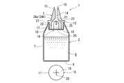
次に、本発明の第2の実施形態による液体用容器について説明する。なお、上記第1の実施形態と同じ部材については同一の符合を付して説明する。
図5に示す液体容器は、上記第1の実施形態で説明した液体用容器1の容器本体2と、仕切材16の形状が異なり、ノズル蓋部5の形状は同じ形状である。
容器本体2は、容器本体2のやや上部側に円錐台形状の中空の肩部4を形成し、肩部4よりも下部は円筒状の胴部7を形成している。本実施形態では、容器本体2の肩部4の上に筒状の口頸部9(図1参照)がなく、開口部27のみが形成されている。そして、開口部27の上端部がノズル蓋部5のフランジ部12の下面に当接している。
Next, a liquid container according to a second embodiment of the present invention will be described. The same members as those in the first embodiment will be described with the same reference numerals.
The liquid container shown in FIG. 5 is different from the container main body 2 of the liquid container 1 described in the first embodiment in the shape of the partition member 16, and the shape of the nozzle lid 5 is the same.
The container body 2 is formed with a truncated cone-shaped hollow shoulder portion 4 slightly above the container body 2, and a cylindrical body portion 7 is formed below the shoulder portion 4. In this embodiment, there is no cylindrical mouth-neck part 9 (see FIG. 1) on the shoulder part 4 of the container body 2, and only the opening part 27 is formed. The upper end portion of the opening 27 is in contact with the lower surface of the flange portion 12 of the nozzle lid portion 5.

仕切材16は、上記第1の実施形態と同様に、周壁部17と底部である円形の隔壁18とからなり、上記実施形態と異なるのは、切れ目の形状のみが異なっている。図5に示すように、本実施形態では、十字形状の隔壁弁20の切れ目を隔壁18の中心部に形成している。この隔壁弁20の切れ目が弁体の開弁部として形成されている。仕切材16が、容器本体2に組み込まれるときは、周壁部17がノズル蓋部5の筒状部10の外周面に嵌合するようにして装着される。この仕切材16を配設することにより、ノズル蓋部5の流通路14と容器本体2の内部との間に隔室22を形成している。隔室22には、移動弁23を形成している。移動弁23については、図4に示すように、上部側の一端に扇状溝24a,24bを形成し、下部側の一端に長溝25が形成されている。
その他の説明を省略した部分については、上記実施形態と同じ形状である。
Similar to the first embodiment, the partition member 16 includes a peripheral wall portion 17 and a circular partition wall 18 that is a bottom portion, and the only difference from the above embodiment is the shape of the cut. As shown in FIG. 5, in this embodiment, the cut of the cross-shaped partition valve 20 is formed at the center of the partition wall 18. The cut of the partition valve 20 is formed as a valve opening portion of the valve body. When the partition member 16 is incorporated into the container body 2, the partition wall 16 is mounted so that the peripheral wall portion 17 is fitted to the outer peripheral surface of the tubular portion 10 of the nozzle lid portion 5. By arranging the partition member 16, a compartment 22 is formed between the flow passage 14 of the nozzle lid 5 and the inside of the container body 2. A moving valve 23 is formed in the compartment 22. As for the moving valve 23, as shown in FIG. 4, fan-shaped grooves 24a and 24b are formed at one end on the upper side, and a long groove 25 is formed at one end on the lower side.
About the part which abbreviate | omitted other description, it is the same shape as the said embodiment.

本実施形態の液体用容器1についての基本的な効果に付いては、上記第1の実施形態と同じであり、使用時に、液体収容室6の内部圧力が上昇し、さらに内圧が上昇すると隔壁弁20の切れ目が開いて隔壁18が開弁状態になり、液体収容室6から隔室22に液体が流出し、移動弁23の扇状溝24a,24bを通って流通路14、注出口15に排出される。
本実施形態では、隔壁弁20の閉塞力によって、液体の内圧力に対する応答性を鈍らせ、移動弁2によって、液体の粘度に適合させた液切れ性の微調整が可能になる。また、容器本体2の押圧の初期において、液体収容室6内の内圧が高まった状態で隔壁弁19が開弁しても、上記移動弁23の液体への規制作用により、ノズル11の注出口15からの液体の飛び出しを防止できる。
ただし、本実施形態では、仕切材16の周壁部17が容器本体2の口頸部3とノズル蓋部5の筒状部10との間に配設されていないので、容器本体2の開口部27とノズル蓋部5のフランジ部12との密閉性の維持を上記第1の実施形態の液体用容器1よりも必要とする。
隔壁18の隔壁弁20の切れ目については、十字形状に形成したが、隔壁弁20の開弁圧力を小さくするような場合により効果がある。なお、線状の切れ目の数について、適宜変更することができる。
その他、効果については上記実施形態と同じである。
The basic effects of the liquid container 1 of the present embodiment are the same as those of the first embodiment. When the internal pressure of the liquid storage chamber 6 increases and the internal pressure further increases during use, the partition wall The opening of the valve 20 is opened, the partition wall 18 is opened, the liquid flows out from the liquid storage chamber 6 into the compartment 22, passes through the fan-shaped grooves 24 a and 24 b of the moving valve 23, and enters the flow passage 14 and the spout 15. Discharged.
In the present embodiment, the responsiveness to the internal pressure of the liquid is blunted by the closing force of the partition valve 20, and the fluidity can be finely adjusted according to the viscosity of the liquid by the moving valve 2. Further, even if the partition valve 19 is opened in the initial stage of pressing the container body 2 while the internal pressure in the liquid storage chamber 6 is increased, the spout of the nozzle 11 is controlled by the action of the moving valve 23 on the liquid. It is possible to prevent liquid from jumping out of 15.
However, in the present embodiment, the peripheral wall portion 17 of the partition member 16 is not disposed between the mouth-and-neck portion 3 of the container body 2 and the cylindrical portion 10 of the nozzle lid portion 5. 27 and the flange part 12 of the nozzle cover part 5 need maintenance of the sealing performance rather than the liquid container 1 of the said 1st Embodiment.
The break of the partition valve 20 of the partition wall 18 is formed in a cross shape, but it is more effective when the valve opening pressure of the partition valve 20 is reduced. The number of linear cuts can be changed as appropriate.
Other effects are the same as in the above embodiment.

次に、本発明の第3の実施形態による液体用容器について説明する。なお、上記第1の実施形態と同じ部材については同一の符合を付して説明する。
図6に示す液体容器は、上記第1及び第2の実施形態で説明した液体用容器1と、仕切材16の取り付ける位置が異なり、上記実施形態では筒状部10に配設したが、本実施形態では、開口部3に配設したことが異なる。
すなわち、本実施形態の容器本体2は、容器本体2のやや上部側に肩部4を形成し、肩部4よりも下部は胴部7を形成し、肩部4よりも上の部位は、肩部4から上方に突出する円筒形状の口頸部9が形成されている。
Next, a liquid container according to a third embodiment of the present invention will be described. The same members as those in the first embodiment will be described with the same reference numerals.
The liquid container shown in FIG. 6 differs from the liquid container 1 described in the first and second embodiments in the position where the partition material 16 is attached. In the above embodiment, the liquid container is disposed in the cylindrical portion 10. In the embodiment, the arrangement is different in the opening 3.
That is, the container main body 2 of the present embodiment forms a shoulder portion 4 slightly above the container main body 2, a lower portion than the shoulder portion 4 forms a trunk portion 7, and a portion above the shoulder portion 4 is A cylindrical mouth and neck portion 9 protruding upward from the shoulder portion 4 is formed.

仕切材16は、上記第1の実施形態と同様に、周壁部17と底部である円形の隔壁18とからなり、本実施形態では、直線状の切れ目を有する隔壁弁19を隔壁18の中心部を通るように形成している。この隔壁弁19の切れ目が弁体の開弁部として形成されている。仕切材16が、容器本体2に組み込まれるときは、図1に示す仕切材16とは異なり、仕切材16の向きを逆にして、切れ目を形成した側を上にして、該仕切材16を開口部3に被せる。こうして、周壁部17が容器本体2の頸部9の外周面とノズル蓋部5の筒状部10の内周面との間に狭着されるようにして配設される。この仕切材16を配設することにより、ノズル蓋部5の流通路14と容器本体2の内部との間に隔室22が形成される。
隔室22には、移動弁23を備えている。移動弁23については、図4に示すように、上部側の一端に扇状溝24を形成し、下部側の一端に長溝25が形成されている。
その他の説明を省略した部分については、上記実施形態と同じ形状である。
As in the first embodiment, the partition member 16 includes a peripheral wall portion 17 and a circular partition wall 18 which is a bottom portion. In this embodiment, a partition valve 19 having a straight cut is provided at the center of the partition wall 18. It is formed to pass through. The cut of the partition valve 19 is formed as a valve opening portion of the valve body. When the partitioning material 16 is incorporated into the container body 2, unlike the partitioning material 16 shown in FIG. 1, the partitioning material 16 is reversed with the direction of the partitioning material 16 reversed and the side where the cut is formed facing upward. Cover the opening 3. In this way, the peripheral wall portion 17 is disposed so as to be tightly attached between the outer peripheral surface of the neck portion 9 of the container body 2 and the inner peripheral surface of the tubular portion 10 of the nozzle lid portion 5. By arranging the partition material 16, a compartment 22 is formed between the flow passage 14 of the nozzle lid 5 and the inside of the container body 2.
The compartment 22 is provided with a moving valve 23. As for the moving valve 23, as shown in FIG. 4, a fan-shaped groove 24 is formed at one end on the upper side, and a long groove 25 is formed at one end on the lower side.
About the part which abbreviate | omitted other description, it is the same shape as the said embodiment.

本実施形態の液体用容器1についての基本的な効果に付いては、上記第1の実施形態と同じであり、使用時に、液体収容室6の内部圧力が上昇し、さらに内圧が上昇すると隔壁弁19の切れ目が開いて隔壁18が開弁状態になり、液体収容室6から隔室22に液体が流出し、移動弁23の扇状溝24a,24bを通って流通路14、注出口15に排出される。
本実施形態では、隔壁弁19の閉塞力によって、液体の内圧力に対する応答性を鈍らせ、移動弁2によって、液体の粘度に適合させた液切れ性の微調整が可能になる。また、容器本体2の押圧の初期において、液体収容室6内の内圧が高まった状態で隔壁弁19が開弁しても、上記移動弁23の液体への規制作用により、ノズル11の注出口15からの液体の飛び出しを防止できる。
The basic effects of the liquid container 1 of the present embodiment are the same as those of the first embodiment. When the internal pressure of the liquid storage chamber 6 increases and the internal pressure further increases during use, the partition wall The opening of the valve 19 is opened, the partition wall 18 is opened, the liquid flows out from the liquid storage chamber 6 into the compartment 22, passes through the fan-shaped grooves 24 a and 24 b of the transfer valve 23, and enters the flow passage 14 and the spout 15. Discharged.
In the present embodiment, the responsiveness to the internal pressure of the liquid is dulled by the closing force of the partition valve 19, and it is possible to finely adjust the liquid breakability adapted to the viscosity of the liquid by the moving valve 2. Further, even if the partition valve 19 is opened in the initial stage of pressing the container body 2 while the internal pressure in the liquid storage chamber 6 is increased, the spout of the nozzle 11 is controlled by the action of the moving valve 23 on the liquid. It is possible to prevent liquid from jumping out of 15.

以上、本発明の実施の形態について説明したが、本発明の技術的思想に基づいて、勿論、本発明は種々の変形又は変更が可能である。
例えば、上記実施形態では、仕切材16について、周壁部17と隔壁18とで構成したが、周壁部17を削除し底部である隔壁18のみで構成し、円形の隔壁の外周部を筒状部10の下端若しくは開口部3に接着剤などで固定してもよく、あるいは、それらに一体成形してもよい。開口部3に隔壁18を一体成形するときは、先端の細いノズルを用いて、隔壁弁19,20から容器本体2の内部に液体を収容することができる。
While the embodiments of the present invention have been described above, the present invention can of course be modified or changed in various ways based on the technical idea of the present invention.
For example, in the above-described embodiment, the partition material 16 is configured by the peripheral wall portion 17 and the partition wall 18, but the peripheral wall portion 17 is deleted and only the partition wall 18 that is the bottom is formed, and the outer peripheral portion of the circular partition wall is a cylindrical portion. It may be fixed to the lower end of 10 or the opening 3 with an adhesive or the like, or may be integrally formed therewith. When integrally forming the partition wall 18 in the opening 3, the liquid can be stored in the container body 2 from the partition valve 19, 20 using a nozzle having a thin tip.

本発明の第1の実施形態の液体用容器を上下方向に切断した断面図である。It is sectional drawing which cut | disconnected the container for liquids of the 1st Embodiment of this invention to the up-down direction. 図1の仕切材を仕切材の底部を上にした状態で、上方から見た斜視図である。It is the perspective view which looked at the partition material of FIG. 1 from the upper direction in the state which faced the bottom part of the partition material. 図1の液体用容器を傾倒させて容器本体に内圧を負荷して液体を注出している状態の断面図である。FIG. 2 is a cross-sectional view of a state in which the liquid container in FIG. 1 is tilted to apply an internal pressure to the container body and liquid is poured out. 図1の液体用容器の隔室に配設している移動弁を上方から見た斜視図である。It is the perspective view which looked at the movement valve arrange | positioned in the compartment of the liquid container of FIG. 1 from upper direction. 本発明の第2の実施形態の液体用容器を上下方向に切断した断面図(液体用容器の下部には仕切材の底面図を示す)である。It is sectional drawing which cut | disconnected the container for liquids of the 2nd Embodiment of this invention to the up-down direction (the bottom view of a partition material is shown in the lower part of the container for liquids). 本発明の第3の実施形態の液体用容器を上下方向に切断した断面図(液体用容器の下部には仕切材の底面図を示す)である。It is sectional drawing which cut | disconnected the container for liquids of the 3rd Embodiment of this invention to the up-down direction (the bottom view of a partition material is shown in the lower part of the container for liquids). 従来例における液体用容器を上下方向に切断した断面図である。It is sectional drawing which cut | disconnected the container for liquids in a prior art example to the up-down direction.

符号の説明Explanation of symbols

1 液体用容器
2 容器本体
3,27 開口部
5 ノズル蓋部
9 口頸部
10 筒状部
11 ノズル
14 流通路
16 仕切材
17 周壁部
18 隔壁
19,20 隔壁弁
22 隔室
DESCRIPTION OF SYMBOLS 1 Liquid container 2 Container main body 3,27 Opening part 5 Nozzle cover part 9 Mouth neck part 10 Cylindrical part 11 Nozzle 14 Flow path 16 Partition material 17 Peripheral wall part 18 Bulkhead 19, 20 Bulkhead valve 22 Partition

Claims (3)

胴部が可撓性を有する容器本体と該容器本体の開口部に取付けられるノズル蓋部とを備え、該ノズル蓋部には前記開口部に配設される筒状部と前記容器本体の開口部よりも外側に突出するノズル部とを備え、
前記筒状部又は前記容器本体に該筒状部と前記容器本体内の液体収容室とを仕切る隔壁を設けることによって、前記ノズル部と前記液体収容室との間に隔室を形成した液体用容器において、
前記隔壁には、前記液体収容室の内方側への押圧時に前記液体収容室の内圧力によって開弁し前記液体収容室側から前記隔室側に液体の流れを許容し、前記液体収容室への押圧力の解除時に前記液体収容室の減圧力によって開弁し前記隔室側から前記液体収容室への液体の流れを許容する切れ目を形成した隔壁弁を設け、
前記隔室には、重力によって該隔室内を移動する移動弁を配設し、該移動弁の一端には前記容器本体の傾倒時に前記ノズル部の液体流通路における前記隔室側の一端を閉塞して液体の流通量を制限する規制部を形成し、
前記移動弁の一端が前記ノズル部の液体流通路側に位置し、他端が前記隔壁側に位置するように前記移動弁と前記隔室とを形成し、
該規制部には前記移動弁の前記液体流通路の閉塞時に、前記隔室と前記流通路とを連通する溝を形成したことを特徴とする液体用容器。
The body includes a container body having flexibility and a nozzle lid attached to the opening of the container body, and the nozzle lid includes a cylindrical portion disposed in the opening and an opening of the container body. A nozzle part protruding outward from the part,
For the liquid in which a partition is formed between the nozzle portion and the liquid storage chamber by providing a partition for partitioning the cylindrical portion and the liquid storage chamber in the container main body in the cylindrical portion or the container main body. In the container,
The partition wall is opened by an internal pressure of the liquid storage chamber when pressed toward the inner side of the liquid storage chamber, allowing a liquid flow from the liquid storage chamber side to the compartment side, and the liquid storage chamber Provided with a partition valve that is opened by a decompression force of the liquid storage chamber when releasing the pressing force to form a break that allows a liquid flow from the compartment side to the liquid storage chamber;
The compartment is provided with a movement valve that moves in the compartment by gravity, and one end of the movement valve is closed at one end of the liquid flow passage of the nozzle portion on the compartment side when the container body is tilted. To form a restricting part that restricts the flow rate of liquid ,
Forming the transfer valve and the compartment so that one end of the transfer valve is located on the liquid flow path side of the nozzle portion and the other end is located on the partition side;
A liquid container characterized in that a groove is formed in the restricting portion to connect the compartment and the flow passage when the liquid flow passage of the transfer valve is closed .
前記移動弁の他端側端部に前記容器本体の径方向に延びる溝を形成したことを特徴とする請求項1に記載の液体用容器。 Liquid container of the claims 1 serial mounting, characterized in that a groove extending radially of the container body to the other end of the moving valve. 前記隔壁に該隔壁の周囲から立ち上がる周壁部を形成し、該周壁部の内周面によって前記筒状部の外周部を覆うようにしたことを特徴とする請求項1又は2に記載の液体用容器。 Forming a peripheral wall rising from the periphery of the partition wall to the partition wall, liquid according to claim 1 or 2, characterized in that to cover the outer periphery of the tubular portion by the inner peripheral surface of the peripheral wall portion container.
JP2008065804A 2008-03-14 2008-03-14 Container for liquid Active JP5116521B2 (en)

Priority Applications (1)

Application Number Priority Date Filing Date Title
JP2008065804A JP5116521B2 (en) 2008-03-14 2008-03-14 Container for liquid

Applications Claiming Priority (1)

Application Number Priority Date Filing Date Title
JP2008065804A JP5116521B2 (en) 2008-03-14 2008-03-14 Container for liquid

Publications (2)

Publication Number Publication Date
JP2009220843A JP2009220843A (en) 2009-10-01
JP5116521B2 true JP5116521B2 (en) 2013-01-09

Family

ID=41238079

Family Applications (1)

Application Number Title Priority Date Filing Date
JP2008065804A Active JP5116521B2 (en) 2008-03-14 2008-03-14 Container for liquid

Country Status (1)

Country Link
JP (1) JP5116521B2 (en)

Families Citing this family (3)

* Cited by examiner, † Cited by third party
Publication number Priority date Publication date Assignee Title
JP6039984B2 (en) * 2012-09-28 2016-12-07 株式会社吉野工業所 Discharge container
CN107406176B (en) * 2015-03-02 2020-05-15 东洋制罐集团控股株式会社 Nozzle with a nozzle body
JP7039745B1 (en) * 2021-03-19 2022-03-22 サンメディカル株式会社 Liquid container

Family Cites Families (2)

* Cited by examiner, † Cited by third party
Publication number Priority date Publication date Assignee Title
JPS4817242U (en) * 1971-06-18 1973-02-27
JP2005138900A (en) * 2003-10-16 2005-06-02 Daipura Kk Liquid packaging container

Also Published As

Publication number Publication date
JP2009220843A (en) 2009-10-01

Similar Documents

Publication Publication Date Title
US9924775B2 (en) Powder discharging container
KR101682033B1 (en) Vial for packaging a liquid having a drip dispensing head
US6499632B2 (en) Pressure control device for maintaining a constant predetermined pressure in a container
US9585459B2 (en) Vacuum container for cream type cosmetic
JP6727123B2 (en) Dispenser with fluid reservoir containing divider or porous material
US9308541B2 (en) Pump-dispensing container
CN110831703B (en) Liquid dispenser with vented bottle and discharge head therefor
JP2016529169A5 (en)
JP5116521B2 (en) Container for liquid
JP6125887B2 (en) Double container
JP5055281B2 (en) Eye drops container
CN105705436A (en) Refillable spray bottle
JP2011098768A (en) Quantifying discharge cap
US20080061084A1 (en) Venting system for a product dispensing device
JP5281957B2 (en) Container for liquid
JP4906483B2 (en) Container for liquid
JP6366518B2 (en) Squeeze foamer container
JP4808096B2 (en) Discharge container with internal pressure absorption mechanism
JP6637830B2 (en) Discharge cap
KR102295465B1 (en) Dispenser for liquid products
KR100858320B1 (en) container for fluid
JP2007069931A (en) Storing container for content
GB2467579A (en) Container with metering valve for dispensing fluid containing a suspended solid
JP2016008049A (en) Liquid container
JP2008143554A (en) Liquid vessel

Legal Events

Date Code Title Description
A621 Written request for application examination

Free format text: JAPANESE INTERMEDIATE CODE: A621

Effective date: 20101125

A977 Report on retrieval

Free format text: JAPANESE INTERMEDIATE CODE: A971007

Effective date: 20120622

A131 Notification of reasons for refusal

Free format text: JAPANESE INTERMEDIATE CODE: A131

Effective date: 20120717

A521 Written amendment

Free format text: JAPANESE INTERMEDIATE CODE: A523

Effective date: 20120910

TRDD Decision of grant or rejection written
A01 Written decision to grant a patent or to grant a registration (utility model)

Free format text: JAPANESE INTERMEDIATE CODE: A01

Effective date: 20121002

A01 Written decision to grant a patent or to grant a registration (utility model)

Free format text: JAPANESE INTERMEDIATE CODE: A01

A61 First payment of annual fees (during grant procedure)

Free format text: JAPANESE INTERMEDIATE CODE: A61

Effective date: 20121016

R150 Certificate of patent or registration of utility model

Free format text: JAPANESE INTERMEDIATE CODE: R150

Ref document number: 5116521

Country of ref document: JP

Free format text: JAPANESE INTERMEDIATE CODE: R150

FPAY Renewal fee payment (event date is renewal date of database)

Free format text: PAYMENT UNTIL: 20151026

Year of fee payment: 3

R250 Receipt of annual fees

Free format text: JAPANESE INTERMEDIATE CODE: R250

R250 Receipt of annual fees

Free format text: JAPANESE INTERMEDIATE CODE: R250

R250 Receipt of annual fees

Free format text: JAPANESE INTERMEDIATE CODE: R250