JP5115952B2 - Noise suppression device and noise suppression method - Google Patents
Noise suppression device and noise suppression method Download PDFInfo
- Publication number
- JP5115952B2 JP5115952B2 JP2007071688A JP2007071688A JP5115952B2 JP 5115952 B2 JP5115952 B2 JP 5115952B2 JP 2007071688 A JP2007071688 A JP 2007071688A JP 2007071688 A JP2007071688 A JP 2007071688A JP 5115952 B2 JP5115952 B2 JP 5115952B2
- Authority
- JP
- Japan
- Prior art keywords
- time
- matrix
- information
- estimated value
- vector
- Prior art date
- Legal status (The legal status is an assumption and is not a legal conclusion. Google has not performed a legal analysis and makes no representation as to the accuracy of the status listed.)
- Active
Links
Images


Landscapes
- Filters That Use Time-Delay Elements (AREA)
Description
本発明は、カルマンフィルタに基づく雑音抑圧装置および雑音抑圧方法に関する。 The present invention relates to a noise suppression device and a noise suppression method based on a Kalman filter.
所望の情報に不必要な情報が混在した受信情報(付加雑音などにより破損した情報)から不必要な情報を取り除き、所望情報のみを抽出することは、音声や無線通信、画像、姿勢制御などの分野における重要な技術であり、近年盛んに研究開発が行われている。 It is necessary to remove unnecessary information from received information (information damaged due to additional noise, etc.) that contains unnecessary information in desired information, and to extract only desired information, such as voice, wireless communication, image, attitude control, etc. It is an important technology in the field and has been actively researched and developed in recent years.
例えば、音声分野における公知の雑音抑圧方法としては、単一のマイクロホンを用いた方法や、複数のマイクロホンから構成されるマイクロホンアレイを用いた方法が提案されている。 For example, as a known noise suppression method in the voice field, a method using a single microphone or a method using a microphone array composed of a plurality of microphones has been proposed.
しかしながら、マイクロホンアレイを用いた方法では、雑音信号の数が増大すると、マイクロホンの数も比例して増加することが避けらず、コストが増大する。そのため、現在は、単一のマイクロホンを用いた雑音抑圧方法の開発が主流となっている。 However, in the method using the microphone array, when the number of noise signals increases, the number of microphones inevitably increases in proportion to the cost, and the cost increases. Therefore, at present, development of noise suppression methods using a single microphone has become the mainstream.
単一のマイクロホンしか用いない従来の雑音抑圧方法のアルゴリズムとしては、以下のようなものが知られている。 The following are known as algorithms of a conventional noise suppression method that uses only a single microphone.
非特許文献1記載のANC(適応ノイズキャンセラ)アルゴリズムは、音声信号の周期性を利用してノイズ信号を低減する。
The ANC (adaptive noise canceller) algorithm described in Non-Patent
非特許文献2には、線形予測に基づいた雑音抑圧アルゴリズムが記載されている。このアルゴリズムは、ピッチ推定や、雑音パワースペクトラム、雑音の平均方向に関する事前知識を必要としない。
Non-Patent
また、上記アルゴリズムとは別に、カルマンフィルタに基づいた雑音抑圧アルゴリズムが、非特許文献3に提案されている。このアルゴリズムは、音声信号を自己回帰(AR:AutoRegressive)過程でモデル化する。さらに、このアルゴリズムは、自己回帰モデルの係数(以下「AR係数」という)を推定し、推定したAR係数を用いたカルマンフィルタに基づいて雑音抑圧を実行する。このアルゴリズムは、AR係数を推定する必要があるため、上記他のアルゴリズムとは本質的に異なっている。
In addition to the above algorithm, Non-Patent
カルマンフィルタに基づいたアルゴリズムの多くは、通常、2段階で動作する。すなわち、このようなアルゴリズムは、最初にAR係数を推定し、次に推定したAR係数を用いたカルマンフィルタに基づいて雑音抑圧を行う。
しかしながら、非特許文献1に記載された公知のアルゴリズムは、音声信号のピッチ周期の正確な推定を必要とする。そのため、このアルゴリズムは、その雑音抑圧能力が付加雑音によって劣化してしまうという問題点を有している。
However, the known algorithm described in Non-Patent
この点、非特許文献2記載のアルゴリズムは、音声信号のピッチ周期の正確な推定を必要とせずに、雑音抑圧が可能である。さらに、このアルゴリズムは、その原理が単純であり、演算量を少なくすることができるといった長所を有している。しかし、このアルゴリズムは、その雑音抑圧能力が入力音声信号の周期性や線形性などの特性に依存している。言い換えると、このアルゴリズムは、雑音抑圧能力の中に音声信号に依存するパラメータが存在しているため、その実用には一定の限界がある。
In this regard, the algorithm described in Non-Patent
非特許文献3記載のアルゴリズムは、強力な雑音抑圧能力を有し、特に高い音質を得たい音響分野への応用に適した手法である。
The algorithm described in Non-Patent
しかしながら、一方で、このアルゴリズムは、AR係数を必要とするため、AR係数の推定精度に雑音抑圧性能(つまり、当該カルマンフィルタアルゴリズムの性能)が大きく依存してしまうという問題点を有している。すなわち、AR係数が正確に推定されない場合、雑音を除去し切れないのみならず、場合によっては雑音に加えて音声信号まで除去してしまう可能性がある。これらは、雑音除去された音声信号の音質の劣化を引き起こす要因となりうる。 However, since this algorithm requires an AR coefficient, it has a problem that noise suppression performance (that is, the performance of the Kalman filter algorithm) greatly depends on the estimation accuracy of the AR coefficient. That is, if the AR coefficient is not accurately estimated, not only the noise cannot be completely removed, but also the voice signal may be removed in addition to the noise. These can be a cause of deterioration of the sound quality of the sound signal from which noise is removed.
この点、一般には、AR係数の正確な推定は困難である。AR係数の正確な推定は、例えば、雑音除去であれば、クリアな音声信号に依存しているからである。このことは、音声信号が既知でなければならないことを意味しているため、リアルタイム処理は困難となる。また、仮に何らかの手法でリアルタイムにAR係数を正確に推定することが可能となったとしても、処理が増加するため演算量の問題は避けられない。 In this respect, generally, it is difficult to accurately estimate the AR coefficient. This is because accurate estimation of the AR coefficient depends on a clear audio signal in the case of noise removal, for example. This means that the audio signal must be known, so real-time processing becomes difficult. Even if it becomes possible to accurately estimate the AR coefficient in real time by any method, the problem of computational complexity is inevitable because the processing increases.
本発明は、かかる点に鑑みてなされたものであり、AR係数の推定を必要としないシンプルで雑音抑圧能力が高い、カルマンフィルタに基づく雑音抑圧装置および雑音抑圧方法を提供することを目的とする。 The present invention has been made in view of the above points, and an object thereof is to provide a noise suppression device and a noise suppression method based on a Kalman filter that do not require estimation of an AR coefficient and have a high noise suppression capability.
本発明の雑音抑圧装置は、所望の情報に不必要な情報が混在した情報を取得する取得手段と、カルマンフィルタのみを用いて、取得された情報から前記不必要な情報を除去して前記所望情報を抽出する抽出手段と、を有し、前記カルマンフィルタは、状態空間モデルの観測方程式において自己回帰モデルの係数を使用しないように構成されている、構成を採る。 The noise suppression apparatus according to the present invention removes the unnecessary information from the acquired information by using only an acquisition unit that acquires information in which unnecessary information is mixed in desired information and a Kalman filter. And the Kalman filter adopts a configuration in which the coefficient of the autoregressive model is not used in the observation equation of the state space model.
本発明の雑音抑圧方法は、所望の情報に不必要な情報が混在した情報を取得する取得ステップと、カルマンフィルタのみを用いて、取得した情報から前記不必要な情報を除去して前記所望情報を抽出する抽出ステップと、を有し、前記カルマンフィルタは、状態空間モデルの観測方程式において自己回帰モデルの係数を使用しないように構成されている、ようにした。 The noise suppression method of the present invention includes an acquisition step of acquiring information in which unnecessary information is mixed with desired information, and removing the unnecessary information from the acquired information by using only a Kalman filter. The Kalman filter is configured not to use the coefficient of the autoregressive model in the observation equation of the state space model.
本発明によれば、カルマンフィルタを用いつつ、AR係数の推定を必要とすることなく、シンプルな構成で、雑音抑圧能力を向上することができる。 According to the present invention, it is possible to improve the noise suppression capability with a simple configuration without using an AR coefficient estimation while using a Kalman filter.
以下、本発明の実施の形態について、図面を参照して詳細に説明する。 Hereinafter, embodiments of the present invention will be described in detail with reference to the drawings.
(実施の形態1)
図1は、本発明の実施の形態1に係る雑音抑圧装置の構成を示すブロック図である。
(Embodiment 1)
FIG. 1 is a block diagram showing a configuration of a noise suppression apparatus according to
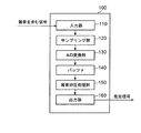
図1に示す雑音抑圧装置100は、入力部110、サンプリング部120、A/D変換部130、バッファ140、雑音抑圧処理部150、および出力部160を有する。
A
入力部110は、観測信号を入力する。観測信号は、信号源からのクリアな信号と、付加雑音信号とが合わさった信号である。入力部110は、例えば、入力したアナログの観測信号を入力処理して、サンプリング部120に出力する。入力処理は、例えば、帯域制限処理や自動利得制御処理などである。
The
サンプリング部120は、所定のサンプリング周波数(例えば、16kHz)で、入力されたアナログの観測信号をサンプリング処理し、A/D変換部130に出力する。A/D変換部130は、サンプリングされた観測信号の振幅値を所定の分解能(例えば、8bit)でA/D変換処理し、バッファ140に送る。バッファ140は、所定のサンプリング数Nの信号フレーム(ブロック)を雑音抑圧処理部150に出力する。
The
雑音抑圧処理部140は、本発明の特徴的な構成要素であり、AR係数を用いないカルマンフィルタを内蔵している。すなわち、カルマンフィルタに基づく従来の雑音抑圧方法(非特許文献3参照)(以下「従来手法」という)では、線形予測を用いてAR係数を推定した後、その結果を用いてカルマンフィルタを実行することで雑音抑圧を実現しているのに対し、本発明の雑音抑圧方法(以下「本手法」という)では、カルマンフィルタのみを用いて雑音抑圧を実現している。そのため、本手法では、信号源からのクリアな信号のみを用いて状態方程式を構成し、そのクリアな信号と付加雑音信号を用いて観測方程式を構成している。以下、雑音抑圧処理部140で行われるカルマンフィルタに基づく雑音抑圧処理動作について詳細に説明する。
The noise
雑音抑圧処理部140に入力される観測信号r(n)は、信号源からのクリアな信号(例えば、音声信号など)d(n)以外に付加雑音信号v(n)を含んでおり、次の式(1)を満たす。
![]()
![]()
従来のAR過程に基づくモデル化方法(従来手法)では、信号d(n)は、AR係数を用いて次の式(2)でモデル化されると仮定している。

公知のように、従来手法では、付加雑音信号v(n)は、零平均であり、白色雑音であることが前提条件である。言い換えると、従来手法では、信号d(n)と付加雑音信号v(n)は無相関であり、つまり、次の式(3)を満たす。
![]()
![]()
AR係数は、AR係数推定アルゴリズムにより推定される。従来手法において最も重要な点は、カルマンフィルタを用いた高性能の雑音抑圧を達成するために、AR係数の正確な推定を必要とすることである。このことからも、カルマンフィルタの雑音抑圧能力がAR係数の推定精度に大きく依存しているため雑音抑圧能力が大きく劣化することは容易に想像可能である。 The AR coefficient is estimated by an AR coefficient estimation algorithm. The most important point in the conventional method is that accurate estimation of the AR coefficient is required to achieve high-performance noise suppression using the Kalman filter. From this, it can be easily imagined that the noise suppression capability of the Kalman filter greatly deteriorates because the noise suppression capability greatly depends on the estimation accuracy of the AR coefficient.
本手法では、AR係数を用いずにカルマンフィルタの状態空間モデル、つまり音源信号からのクリアな信号のみを用いて状態方程式、およびそのクリアな信号と付加雑音信号とを用いて観測方程式を構成している。 In this method, the state equation of the Kalman filter without using the AR coefficient, that is, the state equation using only the clear signal from the sound source signal, and the observation equation using the clear signal and the additional noise signal are constructed. Yes.
以下、本手法での状態空間モデルの構成法について説明する。表記を容易にするために、まずK×1次の信号ベクトルxp(n)を次の式(4)で定義する。添え字“p”は本発明により考案された表現であることを示す。
![]()
![]()
次に、式(2)と同様にして信号d(n)のモデルを構成する。ここでは、AR係数を用いないとしても、従来手法と同様に、未知のK×K次の状態遷移行列Φp(n+1)と、K×1次の駆動雑音ベクトルδp(n+1)を導入する。これにより、本実施の形態の状態空間モデル(信号ベクトルにより記述される)の状態方程式の形として、次の式(5)が定まる。
![]()
![]()
式(5)が等式としてAR係数を用いずに成立するためには、K×K次の状態遷移行列Φp(n+1)、K×1次の駆動雑音ベクトルδp(n+1)は、次の式(6)および式(7)を満たすことが求められる。
![]()
![]()
したがって、式(5)は次の式(8)に書き直せる。
式(6)で表されるK×K次の状態遷移行列Φp(n+1)の行列要素は0と1のみであり、特に第1行がすべて0である。このことは、本手法の状態空間モデルの特徴の一つである。また、上記から明らかなように、式(5)、式(6)、式(7)の導出において、駆動雑音ベクトルδp(n+1)に対して前提条件を与えていないことに注意すべきである。すなわち、駆動雑音ベクトルδp(n+1)は有色であってよい。この理由については後述する。 The matrix elements of the K × K-order state transition matrix Φ p (n + 1) represented by Expression (6) are only 0 and 1, and in particular, all the first rows are 0. This is one of the features of the state space model of this method. Further, as is clear from the above, it should be noted that no precondition is given to the drive noise vector δ p (n + 1) in the derivation of the equations (5), (6), and (7). is there. That is, the driving noise vector δ p (n + 1) may be colored. The reason for this will be described later.
本手法のカルマンフィルタアルゴリズムでは、特異値分解を避けるためにK×1次の観測ベクトルyp(n+1)を次の式(9)で定義する。
![]()
![]()
よって、式(1)および式(9)から、本手法の状態空間モデルの観測方程式として、次の式(10)が導出される。
![]()
![]()
![]()
![]()
以上より、本手法のカルマンフィルタアルゴリズムで用いる状態空間モデルの状態方程式および観測方程式として、式(5)および式(10)がそれぞれ求められた。 From the above, Equation (5) and Equation (10) were obtained as the state equation and the observation equation of the state space model used in the Kalman filter algorithm of the present method, respectively.
図2は、本実施の形態に係る雑音抑圧装置の状態空間モデルを説明するブロック線図である。 FIG. 2 is a block diagram illustrating a state space model of the noise suppression device according to the present embodiment.
図2において、500は時刻nにおける信号ベクトルxp(n)、501は時刻n+1における信号ベクトルxp(n+1)、502は時刻nにおける観測ベクトルyp(n)、503は時刻nにおける付加雑音ベクトルεp(n)、504は時刻n+1における駆動雑音ベクトルδp(n+1)、505は状態遷移行列Φp、506は状態遷移行列Mpである。
In FIG. 2, 500 is a signal vector x p (n) at time n, 501 is a signal vector x p (n + 1) at
図2から理解できるように、本手法のカルマンフィルタアルゴリズムは、駆動雑音が有色であるにもかかわらず、従来のカルマンフィルタアルゴリズムと同様の手順で実行できる(理由は後述する)。本手法のカルマンフィルタアルゴリズムに基づいた信号推定は、後述するフローチャートに従って行われる。 As can be understood from FIG. 2, the Kalman filter algorithm of the present method can be executed in the same procedure as the conventional Kalman filter algorithm even though the driving noise is colored (the reason will be described later). Signal estimation based on the Kalman filter algorithm of this method is performed according to a flowchart described later.
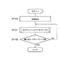
図3は、本実施の形態に係る雑音抑圧装置のカルマンフィルタアルゴリズムに基づく信号推定手順を説明するフローチャートである。 FIG. 3 is a flowchart for explaining a signal estimation procedure based on the Kalman filter algorithm of the noise suppression apparatus according to the present embodiment.
まず、推定信号ベクトルの初期値xe(0|0)、推定誤差の共分散行列の初期値P(0|0)およびスカラー量である付加雑音ベクトルの共分散Rεp(n)[i,j]の値を、次の式(13)に示すように設定する(ST100)。
ここで、Iは単位行列である。また、σv 2は付加雑音信号v(n)の雑音分散であり、既知と仮定している。もし付加雑音信号v(n)が白色雑音であり零平均であれば、σv 2は、次の式(14)で与えられる。
![]()
![]()
次に、カルマンフィルタアルゴリズムを実行する(ST101)。このカルマンフィルタアルゴリズムの処理手順は、後で詳細に説明する。 Next, the Kalman filter algorithm is executed (ST101). The processing procedure of the Kalman filter algorithm will be described in detail later.
次に、時刻nが所定のサンプル数Nに達したか否かを判定し(ST102)、所定のサンプル数Nに達していない場合は(ST102:NO)、ステップST101に戻って、カルマンフィルタアルゴリズムを繰り返し、所定のサンプル数Nに達した場合は(ST102:YES)、上記一連の処理を終了する。 Next, it is determined whether or not the time n has reached a predetermined number of samples N (ST102). If the predetermined number of samples N has not been reached (ST102: NO), the process returns to step ST101 to perform the Kalman filter algorithm. If the predetermined number N of samples is reached repeatedly (ST102: YES), the above series of processing ends.
本手法では、AR係数を用いずに状態空間モデルを設定している。そのため、従来手法で必要であったAR係数を推定するステップを削減することができ、1段階処理で信号推定が可能となる。このことは本発明の大きな特徴の一つである。 In this method, the state space model is set without using the AR coefficient. Therefore, it is possible to reduce the step of estimating the AR coefficient that is necessary in the conventional method, and it is possible to perform signal estimation by one-stage processing. This is one of the major features of the present invention.
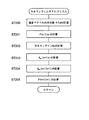
図4は、図3のカルマンフィルタアルゴリズムの処理内容を示すフローチャートである。 FIG. 4 is a flowchart showing the processing contents of the Kalman filter algorithm of FIG.
ここで、開始時の時刻はn+1であり、以下のフローでは、時刻n+1での観測信号r(n+1)および観測ベクトルyp(n+1)と、時刻nでの推定誤差の共分散行列P(n|n)とから、時刻n+1での推定信号ベクトルxpe(n+1|n)を推定し、同時に推定誤差の共分散行列P(n+1|n+1)を更新する。 Here, the start time is n + 1, and in the following flow, the observation signal r (n + 1) and the observation vector y p (n + 1) at time n + 1 and the covariance matrix P (n of the estimation error at time n) | N), the estimated signal vector x pe (n + 1 | n) at time n + 1 is estimated, and at the same time, the covariance matrix P (n + 1 | n + 1) of the estimation error is updated.
まず、次の式(15)を用いて、駆動雑音ベクトルの共分散Rδp(n)[i,j]の値を計算する(ST200)。
次に、推定誤差の共分散行列P(n+1|n)を計算し、更新する(ST201)。ここで、推定誤差の共分散行列P(n+1|n)の更新式は、次の式(16)である。ここでは、以下、添え字“pe”および“e”は、推定値であることを示す。
![]()
![]()
この式(16)を展開すると、次の式(17)となる。
ここで、式(16)の第3項および第4項に注目する。第3項および第4項は、推定信号ベクトルxpe(n|n)と駆動雑音ベクトルδp(n|n)のアンサンブル平均を含んでいる、したがって、推定信号ベクトルxpe(n|n)と駆動雑音ベクトルδp(n|n)とが無相関でない、言い換えれば、駆動雑音ベクトルδp(n|n)が有色のとき、第3項および第4項は0にならない。すなわち、本手法のカルマンフィルタアルゴリズムが、駆動雑音信号が有色信号の場合に、従来と同様なカルマンフィルタアルゴリズム手順で適用可能か否かは、第3項および第4項が、式(15)で表される推定誤差の共分散行列P(n+1|n)の更新にどの程度影響するかによる。 Here, attention is focused on the third and fourth terms of Equation (16). The third and fourth terms include an ensemble average of the estimated signal vector x pe (n | n) and the drive noise vector δ p (n | n), and therefore the estimated signal vector x pe (n | n). And the driving noise vector δ p (n | n) are not uncorrelated, in other words, when the driving noise vector δ p (n | n) is colored, the third and fourth terms do not become zero. That is, whether or not the Kalman filter algorithm of the present method can be applied by the same Kalman filter algorithm procedure as in the past when the driving noise signal is a colored signal is expressed by the equation (15). It depends on how much it affects the update of the covariance matrix P (n + 1 | n) of the estimation error.
そこで、式(17)の第3項に着目する。第3項は、次の式(18)のように、
ここで、次の式(19)のように、
![]()
![]()
![]()
![]()
式(5)および次の式(21)
![]()
![]()
式(23)の第1項は真値のアンサンブル平均、第2項は推定値のアンサンブル平均を示す。したがって、その差は小さく、e(l+1)は無視できる値である。よって、推定誤差の共分散行列P(n+1|n)の更新式(15)は、次の式(24)のように書き直される。このことから、駆動雑音が有色であっても、本手法の式(5)および式(9)から構成される状態空間モデル(状態方程式と観測方程式)であれば、従来手法と同様なカルマンフィルタアルゴリズム手順が適用可能となる。
![]()
![]()
次に、カルマンゲインKp(n+1)を計算する(ST202)。ここで、カルマンゲインKp(n+1)は、次の式(25)で与えられる。
![]()
![]()
そして、これらの値から、まず推定信号ベクトルxpe(n+1|n)を計算する(ST203)。ここで、推定信号ベクトルxpe(n+1|n)は、次の式(26)で与えられる。
![]()
![]()
そして、推定信号ベクトルxpe(n+1|n+1)を計算する(ST204)。ここで、推定信号ベクトルxpe(n+1|n+1)は、次の式(27)で与えられる。
![]()
![]()
最後に、推定誤差の共分散行列P(n+1|n+1)を計算、更新し(ST205)、フローを終了する。ここで、推定誤差の共分散行列P(n+1|n+1)は、次の式(28)で与えられる。
![]()
![]()
雑音抑圧処理部140は、上述した手順、アルゴリズムによって推定された推定信号をを出力部150に出力する。出力部150は、例えば、スピーカやディスプレイ、通信手段、記憶装置などで構成されている。
The noise
AR係数の推定を必要とする従来のカルマンフィルタの問題点は、AR係数の推定精度にカルマンフィルタアルゴリズムの能力が依存していることである。これに対して、本手法は、カルマンフィルタアルゴリズムのみで実行しているため、AR係数の推定精度に依存しない。 A problem of the conventional Kalman filter that requires estimation of the AR coefficient is that the ability of the Kalman filter algorithm depends on the estimation accuracy of the AR coefficient. On the other hand, since this method is executed only by the Kalman filter algorithm, it does not depend on the estimation accuracy of the AR coefficient.
なお、本手法のカルマンアルゴリズムは、以下に説明する更に改良された方法(以下「改良手法」という)によっても実行できる。以下、この改良手法について説明する。 The Kalman algorithm of this method can also be executed by a further improved method (hereinafter referred to as “improved method”) described below. Hereinafter, this improved technique will be described.
改良手法のカルマンアルゴリズムの状態方程式は、上記式(5)と同一である。ただし、観測方程式を、次の式(29)のように書き直す。改良手法の観測方程式(29)は、本手法の観測方程式(10)の一部の要素を取り出してきたものである。
改良手法の大きな特徴の一つは、本手法の観測方程式(10)と改良手法の観測方程式(30)の比較からわかるように、改良前の方法(本手法)における、観測ベクトルyp(n+1)、雑音ベクトルεp(n+1)、および状態遷移行列mpが、それぞれスカラーとベクトルに変更されていることである。したがって、改良手法はより少ない演算量で実行できるであろうことは明らかである。また、上記から明らかなように、改良手法においても、本手法と同様に、駆動雑音ベクトルδp(n+1)に対して前提条件を与えていないことに注意すべきである。すなわち、改良手法においても駆動雑音ベクトルδp(n+1)は有色であってよい。 One of the major features of the improved method is that the observation vector y p (n + 1) in the method before the improvement (this method), as can be seen from the comparison between the observation equation (10) of this method and the observation equation (30) of the improved method. ), The noise vector ε p (n + 1), and the state transition matrix m p are changed to a scalar and a vector, respectively. Therefore, it is clear that the improved method can be executed with a smaller amount of computation. Further, as is apparent from the above, it should be noted that the improved method does not give a precondition to the drive noise vector δ p (n + 1) as in the present method. That is, even in the improved method, the driving noise vector δ p (n + 1) may be colored.
すなわち、式(17)で与えられた推定誤差の共分散行列P(n+1|n)を再度、行列形式で書き下すと、次の式(31)となる。
改良手法を用いたカルマンフィルタアルゴリズムは、図4に示す本手法のカルマンフィルタアルゴリズムとは、カルマンゲインKp(n+1)の計算(ST202)および推定信号ベクトルxpe(n+1|n+1)の計算(ST204)における計算式が異なる。 The Kalman filter algorithm using the improved method is different from the Kalman filter algorithm of the present method shown in FIG. 4 in the calculation of the Kalman gain K p (n + 1) (ST202) and the calculation of the estimated signal vector x pe (n + 1 | n + 1) (ST204). The calculation formula is different.
すなわち、カルマンゲインKp(n+1)の計算式は、次の式(32)、つまり、
また、推定信号ベクトルxpe(n+1|n+1)の計算式は、次の式(34)となる。
ここで、式(34)のxpe(n+1|n+1)の第1要素に着目すると、斜線網掛けではない(つまり、有色雑音の影響を受けない)ことから、駆動雑音が有色であってもクリアな信号の推定信号を得られる。したがって、改良手法も、本手法と同様に、従来のカルマンフィルタアルゴリズムで実行可能である。既に述べたように、改良手法では、本手法に比べて、演算量を低減できる。しかしながら、本手法が観測ベクトルyp(n+1)を用いているのに対して、改良手法方法では、スカラー量である観測信号y‘p(n+1)を用いている。そのサイズの違いから、過去の観測量をより積極的に用いることができる本手法のほうが、より雑音抑圧能力が高いことは明らかである。 Here, paying attention to the first element of x pe (n + 1 | n + 1) in Expression (34), since it is not hatched (that is, not affected by the colored noise), even if the driving noise is colored, A clear estimated signal can be obtained. Therefore, the improved method can be executed by the conventional Kalman filter algorithm as in the present method. As described above, the improved method can reduce the amount of calculation compared to the present method. However, while this method uses the observation vector y p (n + 1), the improved method uses the observation signal y ′ p (n + 1) that is a scalar quantity. From the difference in size, it is clear that this method, which can use past observations more actively, has higher noise suppression capability.
以上をまとめると、本発明における上記二つの手法(本手法および改良手法)は、カルマンフィルタに必要な状態空間モデルの観測方程式を変更することによって、演算量を大幅に減少させることが可能である。より具体的には、本発明における上記二つの手法では、AR係数の推定を必要としないため、その演算量は従来手法に比べて少ない。また、改良手法では、演算に用いる変数のサイズが本手法に比べて小さいため、その演算量は本手法に比べて少ない。すなわち、演算量に関して、
改良手法<本手法<従来手法
である。
In summary, the above two methods in the present invention (the present method and the improved method) can greatly reduce the amount of calculation by changing the observation equation of the state space model necessary for the Kalman filter. More specifically, the above two methods in the present invention do not require estimation of the AR coefficient, and therefore the amount of calculation is less than that of the conventional method. Further, in the improved method, the size of the variable used for the calculation is smaller than that of the present method, so that the amount of calculation is smaller than that of the present method. That is, regarding the amount of calculation,
Improved method <this method <conventional method.
また、本発明における上記二つの手法を、例えば、半導体集積回路や半導体回路などのハードウエアとして実施する場合、また、パーソナルコンピュータなどで実行可能なソフトウエアとして実施する場合のいずれにおいても、その構成は従来手法よりも単純化される。したがって、本発明における二つの手法を用いれば、回路規模やプログラム量が大幅に低減できるであろうことは明らかである。 In addition, the above-described two methods in the present invention may be implemented, for example, when implemented as hardware such as a semiconductor integrated circuit or a semiconductor circuit, or as software that can be executed by a personal computer or the like. Is simpler than the conventional method. Therefore, it is clear that the circuit scale and the program amount can be greatly reduced by using the two methods in the present invention.
また、本発明における上記二つの手法は、カルマンフィルタに必要な状態空間モデルの観測方程式を変更することによって、雑音抑圧能力を大幅に向上させることが可能である。より具体的には、本発明における上記二つの手法では、AR係数の推定を必要としないため、雑音抑圧能力がAR係数の推定精度に依存する従来手法に比べて、雑音抑圧能力が高い。また、改良手法では、演算に用いる変数のサイズが本手法に比べて小さいため、過去の観測量を積極的に用いていない。したがって、その雑音抑圧能力は本手法に比べて低い。すなわち、雑音抑圧能力に関して、
従来手法<改良手法<本手法
である。
In addition, the above two methods in the present invention can greatly improve the noise suppression capability by changing the observation equation of the state space model necessary for the Kalman filter. More specifically, since the above two methods in the present invention do not require estimation of AR coefficients, the noise suppression capability is higher than the conventional methods in which the noise suppression capability depends on the estimation accuracy of the AR coefficient. In the improved method, since the size of the variable used for the calculation is smaller than that of the present method, the past observation amount is not actively used. Therefore, its noise suppression capability is low compared to this method. That is, regarding noise suppression capability,
Conventional method <improved method <this method.
例えば、音響分野において、音質を若干落としても(ただし、従来手法よりは高い)、演算速度を速くしたい場合に、改良手法は有効である。 For example, in the acoustic field, the improved technique is effective when it is desired to increase the calculation speed even if the sound quality is slightly reduced (but higher than the conventional technique).
AR係数を用いない本発明における上記二つの手法は、状態方程式の駆動雑音が有色信号となっており、従来のカルマンフィルタの仮定、つまり、駆動雑音が白色信号であるという仮定に反している。しかしながら、本発明の状態空間モデルにおける状態方程式と観測方程式の構造的な性質により、駆動雑音が白色信号である従来のカルマンフィルタアルゴリズと全く同じアルゴリズムで実行可能であり、その理由は上記の通りである。また、本発明の改良手法においても、同様に実行可能であることは上記より明らかである。 The above two methods in the present invention that do not use the AR coefficient are contrary to the assumption of the conventional Kalman filter, that is, the driving noise is a white signal, because the driving noise of the state equation is a colored signal. However, due to the structural nature of the state equation and the observation equation in the state space model of the present invention, it can be executed with the same algorithm as the conventional Kalman filter algorithm in which the driving noise is a white signal, for the reason described above. . In addition, it is clear from the above that the improved technique of the present invention can be similarly implemented.
本発明における上記二つの方法は、AR係数を使わないようにカルマンフィルタを構成する。言い換えると、カルマンフィルタのみで実行可能な雑音抑圧方法であるため、従来の雑音抑圧能力の問題を解決していることは明らかである。 In the above two methods in the present invention, the Kalman filter is configured not to use the AR coefficient. In other words, since it is a noise suppression method that can be executed only by the Kalman filter, it is clear that the conventional problem of noise suppression capability is solved.
(実施の形態2)
実施の形態2は、実施の形態1に示す雑音抑圧装置を音声に適用した場合である。
(Embodiment 2)
The second embodiment is a case where the noise suppression apparatus shown in the first embodiment is applied to speech.
図5は、本発明の実施の形態2に係る雑音抑圧装置の構成を示すブロック図である。
FIG. 5 is a block diagram showing the configuration of the noise suppression apparatus according to
図5に示す雑音抑圧装置200は、本実施の形態の雑音抑圧処理を実行できるパーソナルコンピュータ210、マイクロホン220、サンプリング部120、およびA/D変換部130を有する。
A
パーソナルコンピュータ210は、操作装置211、ディスプレイ212、バスインタフェース213、記録装置214、主記憶メモリ215、および中央演算装置216を有する。操作装置211は、典型的にはキーボートやマウスなどであるが、音声認識装置などを用いてもよい。使用者は、操作装置211を用い、ディスプレイ212で確認をしながらコンピュータを操作できる。
The
パーソナルコンピュータ210において本実施の形態の雑音抑圧処理を実行させるプログラムソフトウエアは、記録装置214に格納されていてもよいし、バスインタフェース213を介して外部からダウンロードされてきてもよい。記録装置214は、典型的にはハードディスク装置であるが、CD−ROM装置やDVD装置、フラッシュメモリなどの可搬性のあるものであってもよい。また、それらの組み合わせであってもよい。
Program software for causing the
サンプリング部120およびA/D変換部130は、パーソナルコンピュータ210内部に格納された内蔵カード(ボード)であってもよいし、バスインタフェース213を経由して接続された外部設置型機器であってもよい。
The
マイクロホン220からの観測音声信号は、サンプリング部120に入力される。サンプリング部120は、所定のサンプリング周波数(例えば、16kHz)で、入力されたアナログの観測音声信号をサンプリング処理し、A/D変換部130に出力する。A/D変換部130は、サンプリングされた観測音声信号の振幅値を所定の分解能(例えば、8bit)でA/D変換処理し、一時格納する。A/D変換部130は、所定のサンプリング数Nの音声フレーム単位で、ディジタル化した観測音声信号をパーソナルコンピュータ210のバスインタフェース213に出力する。
The observation audio signal from the
パーソナルコンピュータ210はバスインタフェース213に出力された観測音声信号を一時、主記憶メモリ215に格納し、その後、所定の音声フレーム(サンプリング数)単位で、雑音抑圧処理を施した上で、再度主記憶メモリ215に格納する。雑音抑圧処理は、主記憶メモリ215や記録装置214に格納されたソフトウエアをバスインタフェース213経由で中央演算装置216に呼び出し、実行させることで行われる。
The
パーソナルコンピュータ210は、使用者の操作により、処理を実行したり、中断、終了させたりする。また使用者の操作により、処理した推定音声信号を外部に出力してもよい。
The
次に、本実施の形態における音声の雑音抑圧処理について、図面を参照しつつ説明する。 Next, speech noise suppression processing in the present embodiment will be described with reference to the drawings.
本実施の形態における音声の雑音抑圧の性能評価の目的で音声波形の数値シミュレーションを行った。 For the purpose of evaluating the performance of speech noise suppression in this embodiment, a numerical simulation of speech waveforms was performed.
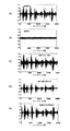
図6は、本実施の形態における音声波形シミュレーションの第1の例の結果を示す図であり、図7は、本実施の形態における音声波形シミュレーションの第2の例の結果を示す図である。また、図8は、本実施の形態における音声波形シミュレーションの第3の例の結果を示す図であり、図9は、本実施の形態における音声波形シミュレーションの第4の例の結果を示す図である。 FIG. 6 is a diagram illustrating a result of the first example of the speech waveform simulation in the present embodiment, and FIG. 7 is a diagram illustrating a result of the second example of the speech waveform simulation in the present embodiment. FIG. 8 is a diagram showing a result of the third example of the speech waveform simulation in the present embodiment, and FIG. 9 is a diagram showing a result of the fourth example of the speech waveform simulation in the present embodiment. is there.
日本人成人男性および女性のオリジナル音声信号(クリアな音声信号)は、無響室において、16kHzのサンプリングレートでサンプリング、ディジタル化した。本例では、二つの音声信号サンプルを検討した。二つの音声信号サンプルは、(A−1)図6(A)に示す無声区間のないクリアな音声信号、(A−2)図7(A)に示す無声区間をもつクリアな音声信号である。それぞれの音声信号サンプルは、以後、音声(A−1)および音声(A−2)と参照する。 Original audio signals (clear audio signals) of Japanese adult men and women were sampled and digitized in an anechoic chamber at a sampling rate of 16 kHz. In this example, two audio signal samples were considered. The two audio signal samples are (A-1) a clear audio signal without an unvoiced section shown in FIG. 6 (A), and (A-2) a clear audio signal with an unvoiced section shown in FIG. 7 (A). . Each audio signal sample is hereinafter referred to as audio (A-1) and audio (A-2).
雑音信号は、人工的な付加雑音信号であり、本例では、二つの雑音信号サンプルを検討した。二つの雑音信号サンプルは、(B−1)図6(B)および図7(B)に示す付加白色ガウス雑音、(B−2)図8(B)および図9(B)に示す付加有色バブル雑音である。それぞれの雑音信号サンプルは、以後、雑音(B−1)および雑音(B−2)と参照される。 The noise signal is an artificial additional noise signal. In this example, two noise signal samples were examined. The two noise signal samples are (B-1) the added white Gaussian noise shown in FIGS. 6 (B) and 7 (B), (B-2) the added colored colors shown in FIG. 8 (B) and FIG. 9 (B). Bubble noise. Each noise signal sample is hereinafter referred to as noise (B-1) and noise (B-2).
雑音信号の雑音分散σv 2は既知として次の式(35)で表されるものとする。すなわち、
![]()
![]()
また、信号雑音比SNRinを式(36)で定義する。
従来手法と本発明の方法(本手法)とによる雑音抑圧の結果を、音声(A−1)および音声(A−2)と雑音(B−1)の組み合わせ、ならびに音声(A−1)および音声(A−2)と雑音(B−2)の組み合わせからなる観測音声信号の信号波形から比較した。 The results of noise suppression by the conventional method and the method of the present invention (the present method) are expressed as speech (A-1), speech (A-2) and noise (B-1), and speech (A-1) and Comparison was made from the signal waveform of the observed voice signal consisting of a combination of voice (A-2) and noise (B-2).
図6(C)と図7(C)は、それぞれ音声(A−1)と雑音(B−1)、音声(A−2)と雑音(B−1)からなる観測音声信号波形である。 FIGS. 6C and 7C show observed sound signal waveforms composed of sound (A-1) and noise (B-1), and sound (A-2) and noise (B-1), respectively.
図6(D)と図7(D)は、それぞれ音声(A−1)と雑音(B−1)、音声(A−2)と雑音(B−1)の合成波形に対して従来手法で雑音抑圧を行った後の推定音声信号波形である。 FIGS. 6D and 7D show a conventional method for a synthesized waveform of speech (A-1) and noise (B-1), speech (A-2) and noise (B-1), respectively. It is an estimated speech signal waveform after noise suppression.
一方、図6(E)と図7(E)は、それぞれ音声(A−1)と雑音(B−1)、音声(A−2)と雑音(B−1)の合成波形に対して従来手法で雑音抑圧を行った後の推定音声信号波形である。 On the other hand, FIG. 6E and FIG. 7E show the conventional waveforms for speech (A-1) and noise (B-1) and speech (A-2) and noise (B-1), respectively. It is an estimated speech signal waveform after performing noise suppression by the technique.
図6(D)と図7(D)に対して図6(A)と図7(A)に示すオリジナルの音声信号とを参照すると、図6(D)と図7(D)に対して図6(A)と図7(A)に示すクリアな音声信号とを比較すると、従来手法による雑音抑圧では、雑音抑圧後に推定音声信号の振幅が小さくなっており、クリアな音声信号が抑圧されていることがわかる。加えて、従来手法による雑音抑圧では、サンプリング数の増加とともに、雑音抑圧後の推定音声信号の波形が、図6(A)と図7(A)に示すクリアな音声信号の波形から変形していく。 Referring to FIG. 6 (A) and FIG. 7 (A) with respect to FIG. 6 (D) and FIG. 7 (D), referring to FIG. 6 (D) and FIG. Comparing the clear speech signal shown in FIG. 6A and FIG. 7A, in the noise suppression by the conventional method, the amplitude of the estimated speech signal is reduced after the noise suppression, and the clear speech signal is suppressed. You can see that In addition, in the noise suppression by the conventional method, as the number of samplings increases, the waveform of the estimated speech signal after noise suppression is transformed from the clear speech signal waveform shown in FIGS. 6 (A) and 7 (A). Go.
さらに、従来手法の雑音抑圧では、無声区間を有する音声(A−2)に対して、推定音声信号が抑圧されるだけでなく、無声区間においてオリジナルの雑音信号と異なる雑音が観察されている。これは、従来手法では、無声区間では信号d(n)がゼロであるにもかかわらず、式(2)でAR係数を求めようとするため、AR係数の値は発散し、不安定な状態を与えるからと推測される。 Furthermore, in the noise suppression of the conventional method, not only the estimated speech signal is suppressed but also noise different from the original noise signal is observed in the unvoiced section for the voice (A-2) having the unvoiced section. This is because in the conventional method, although the signal d (n) is zero in the unvoiced interval, the AR coefficient is obtained by the equation (2), and therefore the AR coefficient value diverges and is unstable. Is presumed to be given.
また、このことから、雑音信号が有色の場合、従来手法の適用は困難であろうことは容易に推測される。 From this, it can be easily estimated that application of the conventional method will be difficult when the noise signal is colored.
従来手法とは対照的に、図6(E)および図7(E)に示す本発明の雑音抑圧では、雑音抑圧後の推定音声信号の波形が、図6(A)と図7(A)に示すクリアな音声信号の波形と非常に似通っている。 In contrast to the conventional method, in the noise suppression of the present invention shown in FIGS. 6 (E) and 7 (E), the waveform of the estimated speech signal after noise suppression is shown in FIGS. 6 (A) and 7 (A). It is very similar to the waveform of a clear audio signal shown in
次に、図8(D)と図9(D)に対して図8(A)と図9(A)に示すクリアな音声信号とを比較すると、従来手法による雑音抑圧では、雑音(B−2)を含む観測音声信号に対して、非常に劣った結果を与えていることがわかる。これは、従来手法では、有色雑音である雑音(B−2)を含んだ観測音声信号に対してAR係数を正確に推定することが困難であるためである。 Next, when the clear audio signal shown in FIG. 8A and FIG. 9A is compared with FIG. 8D and FIG. 9D, noise (B− It can be seen that the inferior result is given to the observed speech signal including 2). This is because it is difficult for the conventional method to accurately estimate the AR coefficient for the observed speech signal including the noise (B-2) that is colored noise.
一方、本発明の雑音抑圧方法では、雑音(B−2)の場合も雑音(B−1)の場合と同程度の雑音抑圧が達成されている。 On the other hand, in the noise suppression method of the present invention, the same level of noise suppression is achieved in the case of noise (B-2) as in the case of noise (B-1).
すなわち、上述のように、本発明の雑音抑制方法は、白色、有色雑音、無声区間の有無に関わらず有効である。これは、本発明の雑音抑制方法の大きな特徴の一つである。 That is, as described above, the noise suppression method of the present invention is effective regardless of the presence or absence of white, colored noise, and unvoiced intervals. This is one of the major features of the noise suppression method of the present invention.
本発明の雑音抑制方法が有色の付加雑音にも適用できることは、既述のカルマンアルゴリズムにおける推定誤差の共分散行列P(n+1|n)の更新式(23)の導出過程からも明らかであるが、上述の本実施の形態の数値シミュレーションは、このことを支持している。 The fact that the noise suppression method of the present invention can also be applied to colored additive noise is obvious from the process of deriving the update equation (23) of the covariance matrix P (n + 1 | n) of the estimation error in the Kalman algorithm described above. The numerical simulation of the present embodiment described above supports this.
次に、雑音抑制性能を数値的に比較するため、雑音抑圧性能SNRoutを式(37)で定義し、その数値シミュレーションを行った。
表1は、本実施の形態における雑音抑圧性能の数値シミュレーションの一例の結果を示す表であり、音声(A−1)と雑音(B−1)の組み合わせにおける、幾つかのSNRin、K(従来手法においては式(2)におけるAR係数の次数、本発明では状態遷移行列Φpの次数)の値における、従来手法と本発明の方法の雑音抑圧性能SNRoutを比較して示している。 Table 1 is a table showing a result of an example of numerical simulation of noise suppression performance in the present embodiment, and shows several SNR in , K ( in a combination of speech (A-1) and noise (B-1). In the conventional method, the noise suppression performance SNR out of the conventional method and the method of the present invention in the value of the order of the AR coefficient in Expression (2), the value of the state transition matrix Φ p in the present invention) is shown in comparison.
表2は、本実施の形態における雑音抑圧性能の数値シミュレーションの他の例の結果を示す表であり、音声(A−1)と雑音(B−1)の組み合わせにおける、幾つかのSNRin、Kの値における、従来手法と本発明の方法の雑音抑圧性能SNRoutを比較して示している。 Table 2 is a table showing the results of another example of the numerical simulation of the noise suppression performance in the present embodiment. Several SNR in in the combination of speech (A-1) and noise (B-1) The noise suppression performance SNR out of the conventional method and the method of the present invention in the value of K is compared and shown.
表1および表2を参照すると、本発明の方法は、すべてのSNRin、Kの値において、従来の方法に比べて雑音抑圧能力を改善していることがわかる。 Referring to Tables 1 and 2, it can be seen that the method of the present invention improves the noise suppression capability compared to the conventional method at all SNR in and K values.
特に、表2に示す有色雑音の場合には、従来手法は非常に劣った結果を与えているのにも関わらず、本発明の方法は表1に示す白色雑音の場合と同程度の結果を示している。すなわち、本発明の雑音抑圧方法は、白色雑音、有色雑音両者に効果的で雑音の性質に堅牢な雑音抑圧方法であるといえる。 In particular, in the case of the colored noise shown in Table 2, the method of the present invention gives the same result as that of the white noise shown in Table 1, although the conventional method gives a very inferior result. Show. That is, it can be said that the noise suppression method of the present invention is a noise suppression method that is effective for both white noise and colored noise and is robust in noise characteristics.
また、表1および表2に見られるように、本発明の方法では、Kの値に対して雑音抑圧性能SNRoutは安定であり、Kの値の増加に伴い増加する傾向にある。対照的に従来の方法では、表1に見られるように、Kの値に対して雑音抑圧性能SNRoutは不安定である。これは、従来手法では、最適なKの値、つまりAR係数の次数を決定することが困難であることを意味している。 Further, as seen in Tables 1 and 2, in the method of the present invention, the noise suppression performance SNR out is stable with respect to the value of K, and tends to increase as the value of K increases. In contrast, in the conventional method, as shown in Table 1, the noise suppression performance SNR out is unstable with respect to the value of K. This means that it is difficult to determine the optimum value of K, that is, the order of the AR coefficient, in the conventional method.
AR係数推定を必要とする従来手法において最も問題になることは、AR係数の次数の正確な推定は一般に困難であることである。なぜなら、AR係数の次数の正確な推定は,例えば雑音除去であれば、クリアな音声信号に依存しているからである。 What is most problematic in the conventional method that requires AR coefficient estimation is that accurate estimation of the order of the AR coefficient is generally difficult. This is because accurate estimation of the order of the AR coefficient depends on a clear speech signal if, for example, noise removal is performed.
このことは、クリアな音声信号が既知でなければならないことを意味しているため、リアルタイム処理は困難となる。AR係数の次数が正確でない場合には、カルマンフィルタアルゴリズの性能が劣化することは容易に想像可能である。また、何らかの手法でリアルタイムに推定することが可能となったとしても、処理が増加することより演算量などの問題を避けることは不可能である。 This means that a clear audio signal must be known, making real-time processing difficult. If the order of the AR coefficient is not accurate, it can be easily imagined that the performance of the Kalman filter algorithm deteriorates. Even if it becomes possible to estimate in real time by some method, it is impossible to avoid problems such as the amount of computation due to the increase in processing.
次に、本実施の形態に係る推定音声信号の音声品質を評価するためにリスニングテストによる主観的評価を行った。 Next, in order to evaluate the voice quality of the estimated voice signal according to the present embodiment, a subjective evaluation by a listening test was performed.
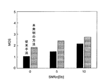
音声品質評価に用いたオリジナル音声信号とオリジナル雑音信号は第2の実施の形態と同一であり、その説明は省略する。雑音信号は、異なるSNRin(0、5、および10[dB])で音声信号に加えた。 The original voice signal and the original noise signal used for the voice quality evaluation are the same as those in the second embodiment, and a description thereof will be omitted. The noise signal was added to the audio signal at different SNR in (0, 5, and 10 [dB]).
音声品質評価は、ACR(絶対範疇評価)に基づいた5段階MOS(平均オピニオン値)を用いたリスニングテストにより行った。50人の聴取者が雑音抑圧により得られた推定音声信号のうち幾つかを評価した。各々の聴取者は、ポイント1からポイント5を決定する。ポイント5が最良である。
The voice quality evaluation was performed by a listening test using a 5-step MOS (average opinion value) based on ACR (absolute category evaluation). Fifty listeners evaluated some of the estimated speech signals obtained by noise suppression. Each listener determines
図10は、本実施の形態における雑音抑圧後の音声品質の主観的評価結果の一つの例を示す図であり、音声(A−1)と雑音(B−1)の組み合わせにおける、従来手法と本発明の方法とリスニングテストの結果を比較して示している。 FIG. 10 is a diagram illustrating an example of a subjective evaluation result of speech quality after noise suppression according to the present embodiment, and shows a conventional method in a combination of speech (A-1) and noise (B-1). The results of the method of the present invention and the listening test are shown in comparison.
また、図11は、本実施の形態における雑音抑圧後の音声品質の主観的評価結果の他の例を示す図であり、音声(A−1)と雑音(B−2)の組み合わせにおける、従来手法と本発明の方法とリスニングテストの結果を比較して示している。 FIG. 11 is a diagram showing another example of the subjective evaluation result of the speech quality after noise suppression in the present embodiment, in the conventional combination of speech (A-1) and noise (B-2). The method, the method of the present invention, and the result of the listening test are shown in comparison.
図10および図11から、本発明の方法で推定した音声信号のスコアは、すべてのSNRin値において従来手法のスコアより高いことがわかる。特にその差は、音声(A−1)と雑音(B−2)の組み合わせに対して大きい。 10 and 11, it can be seen that the score of the speech signal estimated by the method of the present invention is higher than the score of the conventional method in all SNR in values. In particular, the difference is large for the combination of speech (A-1) and noise (B-2).
以上より、本発明の雑音抑圧方法は、音声信号の音声品質を犠牲にすることのない、白色雑音、有色雑音に効果的な優れた雑音抑圧方法であるといえる。 From the above, it can be said that the noise suppression method of the present invention is an excellent noise suppression method effective for white noise and colored noise without sacrificing the voice quality of the voice signal.
(実施の形態3)
本発明に係る雑音抑圧装置は、雑音抑圧以外の用途にも応用可能である。以下、その一つの応用例について説明する。
(Embodiment 3)
The noise suppression device according to the present invention can be applied to uses other than noise suppression. Hereinafter, one application example will be described.
図12は、本発明の雑音抑圧方法、つまりAR係数を必要としないカルマンフィルタが適用されたマルチキャリア受信装置の構成を示すブロック図である。 FIG. 12 is a block diagram showing a configuration of a multicarrier receiver to which the noise suppression method of the present invention, that is, a Kalman filter that does not require an AR coefficient is applied.
図12に示すマルチキャリア受信装置300は、主に、検波部301、GI(ガードインターバル)除去部302、チャネル等化部303、チャネル推定部304、FFT部305、復調部306、および復号部307を有する。
12 mainly includes a
本実施の形態において、チャネル推定部304は、本発明の状態空間モデルを用いたカルマンフィルタに基づいたチャネル推定を実行できるように構成されている。より具体的には、チャネル推定部304は、サンプリング部120、A/D変換部130、バッファ140、雑音抑圧処理部150、出力部160を有する構成をとる。
In the present embodiment, the
検波部301は伝送路上で周波数選択性フェージング等の影響を受けた受信信号を、中間周波数で直交検波し、GI除去部402に出力する。GI除去部302は、受信信号のガードインターバルを除去し、シンボル単位に連なった信号をチャネル等化部303と、チャネル推定部304に出力する。
The
チャネル推定部304に入力された信号は、入力部110に出力される。入力部は信号に所定の入力信号処理を施し、サンプリング部120に出力する。サンプリング部120は、所定のサンプリング周波数(例えば16kHz)で、入力されたアナログの受信信号をサンプリング処理し、A/D変換部130に出力する。A/D変換部130は、サンプリングされた受信信号の振幅値を所定の分解能(例えば8bit)でA/D変換処理し、バッファ140に送る。バッファ140は所定のサンプリング数Nの受信信号フレーム(ブロック)を雑音抑圧処理部150に出力する。
The signal input to the
雑音抑圧処理部150は、カルマンフィルタに基づいたチャネル推定をサブキャリア全体、または各サブキャリアついて行い、推定された(サブ)チャネルゲインを出力部160に出力する。出力部160は、入力された推定チャネルゲインをチャネル等化部302に出力する。雑音処理部150での処理の詳細については後述する。
The noise
チャネル等化部303は、入力された推定チャネルゲインを用いて、GI除去部302から入力した信号の同期検波を行い、結果をFFT部305に出力する。FFT部305は、フーリエ変換処理を行い、受信信号を各サブキャリア信号成分に分離して、復調部306に出力する。復調部306は信号の復調処理を行い、結果を復号部307に出力する。復号部307は、信号の復号を行い、デジタルデータを出力する。
本実施の形態では、まず、フェージングチャンネルを既述の状態空間モデルで表現する。マルチキャリア通信において、第kサブキャリアのみに着目すると、その受信信号yk(t)は、次の式(38)
![]()
![]()
表記を容易にするために、N×1次チャネルゲインベクトルhp(n)を次の式(39)で定義する。
![]()
![]()
本実施の形態では、本発明の状態空間モデルを用いてカルマンフィルタに基づき、チャネルゲインの推定値を適応的に求める。状態空間モデルの状態ベクトルxp(n+1)を次の式(40)で定義する。
![]()
![]()
伝送路特性の時間変動を表す状態方程式は、次の式(41)で記述される。
![]()
![]()
![]()
![]()
駆動雑音ベクトルδp(n+1)、雑音信号ベクトルεp(n+1)、状態遷移行列Cp、Dp、定数行列Gは以下の式(43)から式(48)で定義される。
![]()
![]()
![]()
![]()
![]()
![]()
![]()
![]()
上記の定式化は、従来Vector Kermanと呼ばれているチャネルゲイン推定法に、本発明の状態空間モデルを適用したものである。フェージングチャネル間の相関だけでなく、サブチャネル間の相関も利用しているため良い推定精度を有する。しかしながら、例えば、式(38)の状態ベクトルxp(n+1)のサイズはK×Nであり、計算量が増大するといった問題がある。 In the above formulation, the state space model of the present invention is applied to a channel gain estimation method conventionally called Vector Kerman. Since not only the correlation between fading channels but also the correlation between subchannels is used, it has a good estimation accuracy. However, for example, the size of the state vector x p (n + 1) in Expression (38) is K × N, and there is a problem that the amount of calculation increases.
この問題を改良したものが、従来Per Subcarrier Kalmanと呼ばれている手法である。この方法は、上記方法をサブキャリア単位に分割して処理を行うものである。本発明の状態空間モデルを適用した場合、上記、式(40)から式(48)をサブキャリアk単位に分割することで所望の式が得られる。 What improved this problem is a technique conventionally called Per Subcarrier Kalman. In this method, the above method is divided into subcarriers for processing. When the state space model of the present invention is applied, a desired equation can be obtained by dividing Equation (40) to Equation (48) into subcarriers k.
サブキャリア単位への分割は、状態遷移行列Cpを例にとると、式(42)において、N×Nの単位行列、零行列であるIN×N、0N×Nを、スカラー量である1,0に置き換えることに相当する。したがって、行列のサイズは1/Nになり、計算量を低減することができる。無線伝送の場合には、音響分野とは異なり、推定される信号の品質によりも処理速度が要求される。そのため、本方法はより実用的である。 Taking the state transition matrix C p as an example, the subcarrier unit is divided into an N × N unit matrix and a zero matrix I N × N , 0 N × N as scalar quantities in the equation (42). This corresponds to the replacement with a certain 1,0. Therefore, the size of the matrix becomes 1 / N, and the amount of calculation can be reduced. In the case of wireless transmission, unlike the acoustic field, processing speed is required depending on the estimated signal quality. Therefore, this method is more practical.
次に、本実施の形態におけるチャネル推定精度の比較結果の一例について、図面を参照しつつ説明する。 Next, an example of a comparison result of channel estimation accuracy in the present embodiment will be described with reference to the drawings.
チャネル推定精度の比較検討は数値シミュレーションにより行った。数値シミュレーションの条件は次のように設定した。送信フレームは64のシンボルからなり、そのうち4シンボルがパイロットシンボル、60シンボルがデータシンボルである。総送信フレーム数は200、総送信データシンボル数は12000である.評価量はNMSE(Normarized Mean Square Error)を用いた。 A comparative study of channel estimation accuracy was performed by numerical simulation. The numerical simulation conditions were set as follows. The transmission frame is composed of 64 symbols, of which 4 symbols are pilot symbols and 60 symbols are data symbols. The total number of transmission frames is 200, and the total number of transmission data symbols is 12000. The evaluation amount was NMSE (Normarized Mean Square Error).
図13は、本実施の形態におけるチャネル推定精度数値シミュレーションの一つの例の結果を示す図であり、fDT=0.045、(NTs)=0.08μsにおける、信号雑音比SNRに対するNMSE特性を示している。ここでfDは最大ドップラー周波数、TはOFDMシンボル周期、Tsはサンプリング間隔、τmaxは最大遅延スプレッドである。図13から、本発明の方法の推定精度が従来手法に比べ向上していることがわか。これは、本発明の方法では、AR係数の推定誤差によるチャネルの推定精度の劣化が軽減できたためと考えられる。また、fDが180Hzより大きい場合、本発明の方法の性能向上がより大きなものとなることは明らかである。 FIG. 13 is a diagram illustrating a result of one example of the numerical simulation of channel estimation accuracy according to the present embodiment. NMSE with respect to the signal-to-noise ratio SNR at f D T = 0.045 and (NT s ) = 0.08 μs. The characteristics are shown. Where f D is the maximum Doppler frequency, T is the OFDM symbol period, T s is the sampling interval, and τ max is the maximum delay spread. FIG. 13 shows that the estimation accuracy of the method of the present invention is improved as compared with the conventional method. This is presumably because the degradation of the channel estimation accuracy due to the AR coefficient estimation error can be reduced in the method of the present invention. Also, if f D is greater than 180 Hz, the performance improvement of the method of the present invention becomes larger one is obvious.
図14は、本実施の形態におけるチャネル推定精度数値シミュレーションの他の例の結果を示す図であり、SNR=20dB、τmax/(NTs)=0.08μsにおける、最大ドップラー周波数fDに対するNMSE特性を示している。この結果より、本発明の方法は、NMSEが最大ドップラー周波数fDに依存しないため、従来手法より良好な性能を有していることがわかる。すなわち、チャネル間干渉の影響が深刻となるフェージング変動の激しい環境においても、本発明の方法の有効性が確認できる。 FIG. 14 is a diagram showing the results of another example of the channel estimation accuracy numerical simulation according to the present embodiment. NMSE with respect to the maximum Doppler frequency f D when SNR = 20 dB and τ max / (NT s ) = 0.08 μs. The characteristics are shown. From this result, the method of the present invention, since the NMSE is not dependent on the maximum Doppler frequency f D, it can be seen that the prior art technique has a good performance. That is, the effectiveness of the method of the present invention can be confirmed even in an environment where the fading fluctuation is severe where the influence of inter-channel interference becomes serious.
本発明は、上記各実施の形態に限定されるものではない。 The present invention is not limited to the above embodiments.
本発明の雑音抑圧装置は、ノイズが含まれた音声信号(得られた情報)からクリアな音声信号(必要な情報)を取り出すことが可能である。その一つの実施の形態として、カーナビゲーション装置などに必要不可欠な音声認識装置の前処理雑音除去装置が考えられる。 The noise suppression device of the present invention can extract a clear audio signal (necessary information) from an audio signal containing noise (obtained information). As one embodiment thereof, a preprocessing noise removal device for a speech recognition device that is indispensable for a car navigation device or the like can be considered.
また、画像分野においては、何らかの原因でぼけてしまったぼけ画像(得られた情報)からぼけのとれたクリアな画像(必要な情報)を取り出すことが可能であり、画像処理装置として活用可能である。 In the image field, a clear image (necessary information) can be extracted from a blurred image (obtained information) that has been blurred for some reason, and can be used as an image processing apparatus. is there.
さらに、従来、AR過程によるモデル化とカルマンフィルタアルゴリズムとを組み合わせを用いた通信・信号処理全般にわたり、本発明が適応可能であることはいうまでもない。 Furthermore, it goes without saying that the present invention can be applied to communication and signal processing in general using a combination of modeling by an AR process and a Kalman filter algorithm.
また、医療分野では、従来、妊婦の胎児の状況を検査するには、個人が購入することができない高価な装置と高い専門知識とが必要があったが、本発明によれば、妊婦の体から母胎の心音や胎児の心音やその他の音(得られた情報)から不必要な音(情報)を取り除き胎児の心音(必要な情報)のみを取り出すことが可能になり、通院せずとも自宅で胎児の健康状態を、その心音から容易に確認することが可能となる。 Further, in the medical field, conventionally, in order to inspect the condition of a pregnant woman's fetus, an expensive device that cannot be purchased by an individual and high expertise are required. It is possible to remove unnecessary sounds (information) from the heart sounds of the mother and the fetus and other sounds (obtained information), and only the heart sounds of the fetus (necessary information) can be taken out. The fetal health can be easily confirmed from the heart sound.
上記各実施の形態の説明に用いた各機能要素は、例えば、集積回路として実現される。これらは、個別に1チップ化されてもよいし、一部または全てを含むように1チップ化されてもよい。また、集積回路製造後にプログラムすることが可能なFPGA(Field Programmable Gate Array)や、回路を再構成可能なリコンフィギュラブル・プロセッサを利用してもよい。 Each functional element used in the description of the above embodiments is realized as an integrated circuit, for example. These may be individually made into one chip, or may be made into one chip so as to include a part or all of them. Further, an FPGA (Field Programmable Gate Array) that can be programmed after manufacturing the integrated circuit or a reconfigurable processor that can reconfigure the circuit may be used.
さらに、上記各実施の形態はハードウエアに限定されるものではなく、ソフトウエアによってもよい。その逆も真である。また、それらの組み合わせであってもよい。 Further, each of the above embodiments is not limited to hardware, and may be software. The reverse is also true. Moreover, those combinations may be sufficient.
本発明に係る雑音抑圧装置および雑音抑圧方法は、カルマンフィルタを用いつつ、AR係数の推定を必要とすることなく、シンプルな構成で、雑音抑圧能力を向上することができる雑音抑圧装置および雑音抑圧方法として有用である。 The noise suppression device and the noise suppression method according to the present invention are a noise suppression device and a noise suppression method that can improve the noise suppression capability with a simple configuration without using an AR coefficient estimation while using a Kalman filter. Useful as.
100、200 雑音抑圧装置
110 入力部
120 サンプリング部
130 A/D変換部
140 バッファ
150 雑音抑圧処理部
160 出力部
210 パーソナルコンピュータ
211 操作装置
212 ディスプレイ
213 バスインタフェース
214 記録装置
215 主記憶メモリ
216 中央演算装置
220 マイクロホン
300 マルチキャリア受信装置
301 検波部
302 GI除去部
303 チャネル等化部
304 チャネル推定部
305 FFT部
306 復調部
307 復号部
500、501 信号ベクトル
502 観測ベクトル
503 付加雑音信号ベクトル
504 駆動雑音ベクトル
505 状態遷移行列
506 状態遷移行列
DESCRIPTION OF SYMBOLS 100,200
Claims (9)
前記観測情報を取得する取得手段と、
有色雑音を駆動源として用いるカルマンフィルタを用いて、取得された前記観測情報から前記雑音を除去して前記所望情報を抽出する抽出手段と、を有し、
前記カルマンフィルタは、
状態空間モデルの状態方程式において自己回帰モデルの係数を使用しないように構成されている、
雑音抑制装置。 A noise suppression device that estimates the desired information only from observation information in which noise is mixed in the desired information,
Obtaining means for obtaining the observation information;
Using a Kalman filter using colored noise as a driving source , and extracting means for removing the noise from the acquired observation information and extracting the desired information,
The Kalman filter is
It is configured not to use autoregressive model coefficients in the state equation of the state space model,
Noise suppression device.
時刻nのみの観測情報に対して、時刻nまでの情報により前記所望情報を含む時刻n+1のシステムの状態量を推定した場合の推定誤差の第1相関値行列を算出する第1の相関演算部と、
時刻nのみの観測情報に対して、前記第1の相関演算部によって算出された前記推定誤差の第1相関値行列を用いて、時刻n+1までの情報による当該時刻での前記状態量の最適推定値ベクトルと、時刻nまでの情報による時刻n+1での前記状態量の最適推定値ベクトルと、前記観測情報を含む観測量の推定誤差ベクトルと、の関係を規定するための重み係数行列を算出する重み係数算出部と、
時刻nのみの観測情報に対して、時刻nまでの情報による時刻n+1での前記状態量の第1最適推定値ベクトルを算出する第1の最適推定値算出部と、
時刻nのみの観測情報に対して、前記重み係数算出部によって算出された前記重み係数行列を用いて、時刻n+1までの情報による当該時刻での前記状態量の第2最適推定値ベクトルを算出する第2の最適推定値算出部と、
時刻nのみの観測情報に対して、時刻n+1までの情報により当該時刻の前記状態量を推定した場合の推定誤差の第2相関値行列を算出する第2の相関演算部と、
を有する請求項1記載の雑音抑圧装置。 The extraction means includes
A first correlation calculation unit that calculates a first correlation value matrix of an estimation error when the state quantity of the system at time n + 1 including the desired information is estimated from information up to time n with respect to observation information only at time n When,
For observation information only at time n, using the first correlation value matrix of the estimation error calculated by the first correlation calculation unit, optimal estimation of the state quantity at that time by information up to time n + 1 A weighting coefficient matrix for defining the relationship between the value vector, the optimum estimated value vector of the state quantity at time n + 1 based on the information up to time n, and the estimated error vector of the observed quantity including the observation information is calculated. A weighting factor calculation unit;
A first optimum estimated value calculating unit for calculating a first optimum estimated value vector of the state quantity at time n + 1 based on information up to time n with respect to observation information only at time n;
For the observation information only at time n, using the weighting coefficient matrix calculated by the weighting coefficient calculation unit, calculate a second optimal estimated value vector of the state quantity at the time based on information up to time n + 1. A second optimum estimated value calculation unit;
A second correlation calculation unit that calculates a second correlation value matrix of an estimation error when the state quantity at the time is estimated from information up to time n + 1 with respect to observation information only at time n;
The noise suppression device according to claim 1, comprising:
所定の状態遷移行列、与えられた駆動源ベクトルの共分散の要素値、および与えられたまたは前回前記第2の相関演算部によって算出された前記推定誤差の第2相関値行列を用いて、前記推定誤差の第1相関値行列の算出を行い、
前記重み係数算出部は、
前記第1の相関演算部によって算出された前記推定誤差の第1相関値行列、与えられた観測遷移行列、および与えられた雑音ベクトルの共分散の要素値を用いて、前記重み係数行列の算出を行い、
前記第1の最適推定値算出部は、
前記状態遷移行列、および、与えられたまたは前回前記第2の最適推定値算出部によって算出された前記状態量の第2最適推定値ベクトルを用いて、前記状態量の第1最適推定値ベクトルの算出を行い、
前記第2の最適推定値算出部は、
前記第1の最適推定値算出部によって算出された前記状態量の第1最適推定値ベクトル、前記重み係数算出部によって算出された前記重み係数行列、前記観測遷移行列、および時刻n+1のみにおける観測量を用いて、前記状態量の第2最適推定値ベクトルの算出を行い、
前記第2の相関演算部は、
前記重み係数算出部によって算出された前記重み係数行列、前記観測遷移行列、および前記第1の相関演算部によって算出された前記推定誤差の第1相関値行列を用いて、前記推定誤差の第2相関値行列の算出を行う、
請求項2記載の雑音抑圧装置。 The first correlation calculation unit includes:
Using a predetermined state transition matrix, an element value of covariance of a given drive source vector, and a second correlation value matrix of the estimation error given or previously calculated by the second correlation calculation unit, Calculate the first correlation value matrix of the estimation error,
The weight coefficient calculation unit includes:
Calculation of the weighting coefficient matrix using a first correlation value matrix of the estimation error calculated by the first correlation calculation unit, a given observation transition matrix, and a covariance element value of a given noise vector And
The first optimal estimated value calculation unit includes:
Using the state transition matrix and the second optimum estimated value vector of the state quantity given or previously calculated by the second optimum estimated value calculating unit, the first optimum estimated value vector of the state quantity Perform the calculation
The second optimum estimated value calculation unit includes:
The first optimal estimated value vector of the state quantity calculated by the first optimal estimated value calculating unit, the weighting coefficient matrix calculated by the weighting coefficient calculating unit, the observation transition matrix, and the observed amount only at time n + 1 To calculate a second optimum estimated value vector of the state quantity,
The second correlation calculation unit includes:
Using the weight coefficient matrix calculated by the weight coefficient calculation unit, the observation transition matrix, and the first correlation value matrix of the estimation error calculated by the first correlation calculation unit, the second estimation error is calculated. Calculate the correlation value matrix,
The noise suppression device according to claim 2.
前記観測情報を取得する取得ステップと、
有色雑音を駆動源として用いるカルマンフィルタを用いて、取得した前記観測情報から前記雑音を除去して前記所望情報を抽出する抽出ステップと、を有し、
前記カルマンフィルタは、
状態空間モデルの状態方程式において自己回帰モデルの係数を使用しないように構成されている、
雑音抑圧方法。 A noise suppression method for estimating the desired information only from observation information in which noise is mixed in the desired information,
An acquisition step of acquiring the observation information;
An extraction step of extracting the desired information by removing the noise from the acquired observation information using a Kalman filter using colored noise as a driving source , and
The Kalman filter is
It is configured not to use autoregressive model coefficients in the state equation of the state space model,
Noise suppression method.
時刻nのみの観測情報に対して、時刻nまでの情報により前記所望情報を含む時刻n+1のシステムの状態量を推定した場合の推定誤差の第1相関値行列を算出する第1の相関演算工程と、
時刻nのみの観測情報に対して、前記第1の相関演算工程で算出した前記推定誤差の第1相関値行列を用いて、時刻n+1までの情報による当該時刻での前記状態量の最適推定値ベクトルと、時刻nまでの情報による時刻n+1での前記状態量の最適推定値ベクトルと、前記観測情報を含む観測量の推定誤差ベクトルと、の関係を規定するための重み係数行列を算出する重み係数算出工程と、
時刻nのみの観測情報に対して、時刻nまでの情報による時刻n+1での前記状態量の第1最適推定値ベクトルを算出する第1の最適推定値算出工程と、
時刻nのみの観測情報に対して、前記重み係数算出工程で算出した前記重み係数行列を用いて、時刻n+1までの情報による当該時刻での前記状態量の第2最適推定値ベクトルを算出する第2の最適推定値算出工程と、
時刻nのみの観測情報に対して、時刻n+1までの情報により当該時刻の前記状態量を推定した場合の推定誤差の第2相関値行列を算出する第2の相関演算工程と、
を有する請求項4記載の雑音抑圧方法。 The extraction step includes
A first correlation calculation step of calculating a first correlation value matrix of an estimation error when the state quantity of the system at time n + 1 including the desired information is estimated from information up to time n with respect to observation information only at time n When,
For the observation information only at time n, using the first correlation value matrix of the estimation error calculated in the first correlation calculation step, the optimum estimated value of the state quantity at that time by the information up to time n + 1 A weight for calculating a weight coefficient matrix for defining a relationship between a vector, an optimal estimated value vector of the state quantity at time n + 1 based on information up to time n, and an estimated error vector of the observed quantity including the observation information Coefficient calculation step;
A first optimal estimated value calculating step of calculating a first optimal estimated value vector of the state quantity at time n + 1 based on information up to time n with respect to observation information only at time n;
For the observation information only at time n, the second optimal estimated value vector of the state quantity at the time according to the information up to time n + 1 is calculated using the weight coefficient matrix calculated in the weight coefficient calculation step. 2 optimal estimated value calculation steps;
A second correlation calculation step of calculating a second correlation value matrix of an estimation error when the state quantity at the time is estimated from information up to time n + 1 with respect to observation information only at time n;
The noise suppression method according to claim 4, comprising:
所定の状態遷移行列、与えられた駆動源ベクトルの共分散の要素値、および与えられたまたは前回前記第2の相関演算工程で算出した前記推定誤差の第2相関値行列を用いて、前記推定誤差の第1相関値行列の算出を行い、
前記重み係数算出工程は、
前記第1の相関演算工程で算出した前記推定誤差の第1相関値行列、与えられた観測遷移行列、および与えられた雑音ベクトルの共分散の要素値を用いて、前記重み係数行列の算出を行い、
前記第1の最適推定値算出工程は、
前記状態遷移行列、および、与えられたまたは前回前記第2の最適推定値算出工程で算出した前記状態量の第2最適推定値ベクトルを用いて、前記状態量の第1最適推定値ベクトルの算出を行い、
前記第2の最適推定値算出工程は、
前記第1の最適推定値算出工程で算出した前記状態量の第1最適推定値ベクトル、前記重み係数算出工程で算出した前記重み係数行列、前記観測遷移行列、および時刻n+1のみにおける観測量を用いて、前記状態量の第2最適推定値ベクトルの算出を行い、
前記第2の相関演算工程は、
前記重み係数算出工程で算出した前記重み係数行列、前記観測遷移行列、および前記第1の相関演算工程で算出した前記推定誤差の第1相関値行列を用いて、前記推定誤差の第2相関値行列の算出を行う、
請求項5記載の雑音抑圧方法。 The first correlation calculation step includes:
The estimation is performed using a predetermined state transition matrix, a covariance element value of a given drive source vector, and a second correlation value matrix of the estimation error given or previously calculated in the second correlation calculation step. Calculate the first correlation value matrix of error,
The weighting factor calculating step includes
The weighting coefficient matrix is calculated using the first correlation value matrix of the estimation error calculated in the first correlation calculation step, the given observation transition matrix, and the covariance element value of the given noise vector. Done
The first optimum estimated value calculating step includes:
Calculation of the first optimum estimated value vector of the state quantity using the state transition matrix and the second optimum estimated value vector of the state quantity given or previously calculated in the second optimum estimated value calculating step And
The second optimum estimated value calculating step includes:
The first optimal estimated value vector of the state quantity calculated in the first optimal estimated value calculating step, the weighting coefficient matrix calculated in the weighting coefficient calculating step, the observation transition matrix, and the observed amount only at time n + 1 are used. Calculating a second optimal estimated value vector of the state quantity,
The second correlation calculation step includes:
A second correlation value of the estimation error using the weighting coefficient matrix calculated in the weighting coefficient calculation step, the observation transition matrix, and a first correlation value matrix of the estimation error calculated in the first correlation calculation step. Calculate the matrix,
The noise suppression method according to claim 5.
コンピュータに、
前記観測情報を取得する取得ステップと、
有色雑音を駆動源として用いるカルマンフィルタを用いて、取得した前記観測情報から前記雑音を除去して前記所望情報を抽出する抽出ステップと、前記カルマンフィルタは、状態空間モデルの状態方程式において自己回帰モデルの係数を使用しないように構成されている、
を実行させるための雑音抑制プログラム。 A noise suppression program for estimating the desired information only from observation information in which noise is mixed in the desired information,
On the computer,
An acquisition step of acquiring the observation information;
An extraction step of extracting the desired information by removing the noise from the acquired observation information using a Kalman filter using colored noise as a driving source; and the Kalman filter is a coefficient of an autoregressive model in a state equation of a state space model Configured to not use the
Noise suppression program for running.
時刻nのみの観測情報に対して、時刻nまでの情報により前記所望情報を含む時刻n+1のシステムの状態量を推定した場合の推定誤差の第1相関値行列を算出する第1の相関演算工程と、
時刻nのみの観測情報に対して、前記第1の相関演算工程で算出した前記推定誤差の第1相関値行列を用いて、時刻n+1までの情報による当該時刻での前記状態量の最適推定値ベクトルと、時刻nまでの情報による時刻n+1での前記状態量の最適推定値ベクトルと、前記観測情報を含む観測量の推定誤差ベクトルと、の関係を規定するための重み係数行列を算出する重み係数算出工程と、
時刻nのみの観測情報に対して、時刻nまでの情報による時刻n+1での前記状態量の第1最適推定値ベクトルを算出する第1の最適推定値算出工程と、
時刻nのみの観測情報に対して、前記重み係数算出工程で算出した前記重み係数行列を用いて、時刻n+1までの情報による当該時刻での前記状態量の第2最適推定値ベクトルを算出する第2の最適推定値算出工程と、
時刻nのみの観測情報に対して、時刻n+1までの情報により当該時刻の前記状態量を推定した場合の推定誤差の第2相関値行列を算出する第2の相関演算工程と、
を有する請求項7記載の雑音抑圧プログラム。 The extraction step includes
A first correlation calculation step of calculating a first correlation value matrix of an estimation error when the state quantity of the system at time n + 1 including the desired information is estimated from information up to time n with respect to observation information only at time n When,
For the observation information only at time n, using the first correlation value matrix of the estimation error calculated in the first correlation calculation step, the optimum estimated value of the state quantity at that time by the information up to time n + 1 A weight for calculating a weight coefficient matrix for defining a relationship between a vector, an optimal estimated value vector of the state quantity at time n + 1 based on information up to time n, and an estimated error vector of the observed quantity including the observation information Coefficient calculation step;
A first optimal estimated value calculating step of calculating a first optimal estimated value vector of the state quantity at time n + 1 based on information up to time n with respect to observation information only at time n;
For the observation information only at time n, the second optimal estimated value vector of the state quantity at the time according to the information up to time n + 1 is calculated using the weight coefficient matrix calculated in the weight coefficient calculation step. 2 optimal estimated value calculation steps;
A second correlation calculation step of calculating a second correlation value matrix of an estimation error when the state quantity at the time is estimated from information up to time n + 1 with respect to observation information only at time n;
The noise suppression program according to claim 7.
所定の状態遷移行列、与えられた駆動源ベクトルの共分散の要素値、および与えられたまたは前回前記第2の相関演算工程で算出した前記推定誤差の第2相関値行列を用いて、前記推定誤差の第1相関値行列の算出を行い、
前記重み係数算出工程は、
前記第1の相関演算工程で算出した前記推定誤差の第1相関値行列、与えられた観測遷移行列、および与えられた雑音ベクトルの共分散の要素値を用いて、前記重み係数行列の算出を行い、
前記第1の最適推定値算出工程は、
前記状態遷移行列、および、与えられたまたは前回前記第2の最適推定値算出工程で算出した前記状態量の第2最適推定値ベクトルを用いて、前記状態量の第1最適推定値ベクトルの算出を行い、
前記第2の最適推定値算出工程は、
前記第1の最適推定値算出工程で算出した前記状態量の第1最適推定値ベクトル、前記重み係数算出工程で算出した前記重み係数行列、前記観測遷移行列、および時刻n+1のみにおける観測量を用いて、前記状態量の第2最適推定値ベクトルの算出を行い、
前記第2の相関演算工程は、
前記重み係数算出工程で算出した前記重み係数行列、前記観測遷移行列、および前記第1の相関演算工程で算出した前記推定誤差の第1相関値行列を用いて、前記推定誤差の第2相関値行列の算出を行う、
請求項8記載の雑音抑圧プログラム。 The first correlation calculation step includes:
The estimation is performed using a predetermined state transition matrix, a covariance element value of a given drive source vector, and a second correlation value matrix of the estimation error given or previously calculated in the second correlation calculation step. Calculate the first correlation value matrix of error,
The weighting factor calculating step includes
The weighting coefficient matrix is calculated using the first correlation value matrix of the estimation error calculated in the first correlation calculation step, the given observation transition matrix, and the covariance element value of the given noise vector. Done
The first optimum estimated value calculating step includes:
Calculation of the first optimum estimated value vector of the state quantity using the state transition matrix and the second optimum estimated value vector of the state quantity given or previously calculated in the second optimum estimated value calculating step And
The second optimum estimated value calculating step includes:
The first optimal estimated value vector of the state quantity calculated in the first optimal estimated value calculating step, the weighting coefficient matrix calculated in the weighting coefficient calculating step, the observation transition matrix, and the observed amount only at time n + 1 are used. Calculating a second optimal estimated value vector of the state quantity,
The second correlation calculation step includes:
A second correlation value of the estimation error using the weighting coefficient matrix calculated in the weighting coefficient calculation step, the observation transition matrix, and a first correlation value matrix of the estimation error calculated in the first correlation calculation step. Calculate the matrix,
The noise suppression program according to claim 8.
Priority Applications (1)
| Application Number | Priority Date | Filing Date | Title |
|---|---|---|---|
| JP2007071688A JP5115952B2 (en) | 2007-03-19 | 2007-03-19 | Noise suppression device and noise suppression method |
Applications Claiming Priority (1)
| Application Number | Priority Date | Filing Date | Title |
|---|---|---|---|
| JP2007071688A JP5115952B2 (en) | 2007-03-19 | 2007-03-19 | Noise suppression device and noise suppression method |
Publications (3)
| Publication Number | Publication Date |
|---|---|
| JP2008236270A JP2008236270A (en) | 2008-10-02 |
| JP2008236270A5 JP2008236270A5 (en) | 2010-05-06 |
| JP5115952B2 true JP5115952B2 (en) | 2013-01-09 |
Family
ID=39908527
Family Applications (1)
| Application Number | Title | Priority Date | Filing Date |
|---|---|---|---|
| JP2007071688A Active JP5115952B2 (en) | 2007-03-19 | 2007-03-19 | Noise suppression device and noise suppression method |
Country Status (1)
| Country | Link |
|---|---|
| JP (1) | JP5115952B2 (en) |
Cited By (1)
| Publication number | Priority date | Publication date | Assignee | Title |
|---|---|---|---|---|
| JP5721098B2 (en) * | 2008-03-21 | 2015-05-20 | 学校法人東京理科大学 | Noise suppression device and noise suppression method |
Families Citing this family (9)
| Publication number | Priority date | Publication date | Assignee | Title |
|---|---|---|---|---|
| CN101873121B (en) * | 2010-06-09 | 2012-06-27 | 浙江大学 | Method for processing signals of non-linear dynamic system on basis of histogram estimation particle filtering algorithm |
| JP2013120358A (en) * | 2011-12-08 | 2013-06-17 | Nippon Hoso Kyokai <Nhk> | Noise suppression device, noise suppression method and noise suppression program |
| CN103196450B (en) * | 2013-04-02 | 2014-05-21 | 武汉大学 | Kalman filtering method based on analog circuit and analog circuit |
| US10474776B2 (en) | 2014-10-29 | 2019-11-12 | Nec Corporation | Pipe network analysis apparatus, pipe network analysis method, and storage medium |
| CN109787584A (en) * | 2019-01-23 | 2019-05-21 | 桂林航天工业学院 | A Guaranteed Robust Kalman Filter Design Method for Hybrid Uncertain Systems |
| JP7565036B2 (en) * | 2020-09-04 | 2024-10-10 | 公立大学法人公立諏訪東京理科大学 | Hammering diagnosis support device, hammering diagnosis support method, hammering diagnosis support system, and program |
| CN115964361B (en) * | 2022-11-14 | 2023-07-14 | 苏州浪潮智能科技有限公司 | Data enhancement method, system, equipment and computer readable storage medium |
| CN116007661B (en) * | 2023-02-21 | 2023-06-23 | 河海大学 | A Gyro Error Suppression Method Based on Improved AR Model and Smoothing Filter |
| CN116304591B (en) * | 2023-03-06 | 2026-02-03 | 桂林电子科技大学 | Method for removing and realizing strong vibration interference in force signal for polishing robot |
Family Cites Families (1)
| Publication number | Priority date | Publication date | Assignee | Title |
|---|---|---|---|---|
| US7480595B2 (en) * | 2003-08-11 | 2009-01-20 | Japan Science And Technology Agency | System estimation method and program, recording medium, and system estimation device |
-
2007
- 2007-03-19 JP JP2007071688A patent/JP5115952B2/en active Active
Cited By (1)
| Publication number | Priority date | Publication date | Assignee | Title |
|---|---|---|---|---|
| JP5721098B2 (en) * | 2008-03-21 | 2015-05-20 | 学校法人東京理科大学 | Noise suppression device and noise suppression method |
Also Published As
| Publication number | Publication date |
|---|---|
| JP2008236270A (en) | 2008-10-02 |
Similar Documents
| Publication | Publication Date | Title |
|---|---|---|
| JP5115952B2 (en) | Noise suppression device and noise suppression method | |
| US7313518B2 (en) | Noise reduction method and device using two pass filtering | |
| CN112700786B (en) | Speech enhancement method, device, electronic equipment and storage medium | |
| JP5124014B2 (en) | Signal enhancement apparatus, method, program and recording medium | |
| CN108615535B (en) | Voice enhancement method and device, intelligent voice equipment and computer equipment | |
| EP2254112B1 (en) | Noise suppression devices and noise suppression methods | |
| JP4195267B2 (en) | Speech recognition apparatus, speech recognition method and program thereof | |
| TWI420509B (en) | Noise variance estimator for speech enhancement | |
| KR100304666B1 (en) | Speech enhancement method | |
| CN110085249A (en) | The single-channel voice Enhancement Method of Recognition with Recurrent Neural Network based on attention gate | |
| KR101737824B1 (en) | Method and Apparatus for removing a noise signal from input signal in a noisy environment | |
| JP6748304B2 (en) | Signal processing device using neural network, signal processing method using neural network, and signal processing program | |
| US20140177853A1 (en) | Sound processing device, sound processing method, and program | |
| JP6348427B2 (en) | Noise removal apparatus and noise removal program | |
| US10152986B2 (en) | Acoustic processing apparatus, acoustic processing method, and computer program product | |
| CN115223583A (en) | A kind of speech enhancement method, apparatus, equipment and medium | |
| JPH03266899A (en) | Device and method for suppressing noise | |
| CN113689883B (en) | Voice quality evaluation method, system and computer readable storage medium | |
| CN113393852B (en) | Method and system for constructing voice enhancement model and method and system for voice enhancement | |
| CN114495962A (en) | An audio noise reduction method, apparatus, system and computer-readable storage medium | |
| JP7159928B2 (en) | Noise Spatial Covariance Matrix Estimator, Noise Spatial Covariance Matrix Estimation Method, and Program | |
| JP2019060976A (en) | Voice processing program, voice processing method and voice processing device | |
| Hendriks et al. | Speech Enhancement Under a Combined Stochastic-Deterministic Model | |
| JP2001216000A (en) | Noise suppressing method, voice signal processing method and signal processing circuit | |
| JP6221463B2 (en) | Audio signal processing apparatus and program |
Legal Events
| Date | Code | Title | Description |
|---|---|---|---|
| A521 | Request for written amendment filed |
Free format text: JAPANESE INTERMEDIATE CODE: A523 Effective date: 20100316 |
|
| A621 | Written request for application examination |
Free format text: JAPANESE INTERMEDIATE CODE: A621 Effective date: 20100316 |
|
| A131 | Notification of reasons for refusal |
Free format text: JAPANESE INTERMEDIATE CODE: A131 Effective date: 20120612 |
|
| A521 | Request for written amendment filed |
Free format text: JAPANESE INTERMEDIATE CODE: A523 Effective date: 20120810 |
|
| TRDD | Decision of grant or rejection written | ||
| A01 | Written decision to grant a patent or to grant a registration (utility model) |
Free format text: JAPANESE INTERMEDIATE CODE: A01 Effective date: 20121002 |
|
| A01 | Written decision to grant a patent or to grant a registration (utility model) |
Free format text: JAPANESE INTERMEDIATE CODE: A01 |
|
| A61 | First payment of annual fees (during grant procedure) |
Free format text: JAPANESE INTERMEDIATE CODE: A61 Effective date: 20121010 |
|
| R150 | Certificate of patent or registration of utility model |
Free format text: JAPANESE INTERMEDIATE CODE: R150 Ref document number: 5115952 Country of ref document: JP Free format text: JAPANESE INTERMEDIATE CODE: R150 |
|
| FPAY | Renewal fee payment (event date is renewal date of database) |
Free format text: PAYMENT UNTIL: 20151026 Year of fee payment: 3 |
|
| R250 | Receipt of annual fees |
Free format text: JAPANESE INTERMEDIATE CODE: R250 |
|
| R250 | Receipt of annual fees |
Free format text: JAPANESE INTERMEDIATE CODE: R250 |
|
| R250 | Receipt of annual fees |
Free format text: JAPANESE INTERMEDIATE CODE: R250 |
|
| R250 | Receipt of annual fees |
Free format text: JAPANESE INTERMEDIATE CODE: R250 |
|
| S111 | Request for change of ownership or part of ownership |
Free format text: JAPANESE INTERMEDIATE CODE: R313114 |
|
| R350 | Written notification of registration of transfer |
Free format text: JAPANESE INTERMEDIATE CODE: R350 |
|
| R250 | Receipt of annual fees |
Free format text: JAPANESE INTERMEDIATE CODE: R250 |
|
| R250 | Receipt of annual fees |
Free format text: JAPANESE INTERMEDIATE CODE: R250 |
|
| R250 | Receipt of annual fees |
Free format text: JAPANESE INTERMEDIATE CODE: R250 |
|
| R250 | Receipt of annual fees |
Free format text: JAPANESE INTERMEDIATE CODE: R250 |
|
| R250 | Receipt of annual fees |
Free format text: JAPANESE INTERMEDIATE CODE: R250 |
|
| R250 | Receipt of annual fees |
Free format text: JAPANESE INTERMEDIATE CODE: R250 |
|
| R250 | Receipt of annual fees |
Free format text: JAPANESE INTERMEDIATE CODE: R250 |
|
| S111 | Request for change of ownership or part of ownership |
Free format text: JAPANESE INTERMEDIATE CODE: R313117 |
|
| R350 | Written notification of registration of transfer |
Free format text: JAPANESE INTERMEDIATE CODE: R350 |