JP5115415B2 - Portable cutting machine - Google Patents

Portable cutting machine Download PDF

Info

Publication number
JP5115415B2
JP5115415B2 JP2008235419A JP2008235419A JP5115415B2 JP 5115415 B2 JP5115415 B2 JP 5115415B2 JP 2008235419 A JP2008235419 A JP 2008235419A JP 2008235419 A JP2008235419 A JP 2008235419A JP 5115415 B2 JP5115415 B2 JP 5115415B2
Authority
JP
Japan
Prior art keywords
cover
dust
cutting machine
main body
dust collecting
Prior art date
Legal status (The legal status is an assumption and is not a legal conclusion. Google has not performed a legal analysis and makes no representation as to the accuracy of the status listed.)
Expired - Fee Related
Application number
JP2008235419A
Other languages
Japanese (ja)
Other versions
JP2010064226A (en
Inventor
一 菊池
Current Assignee (The listed assignees may be inaccurate. Google has not performed a legal analysis and makes no representation or warranty as to the accuracy of the list.)
Koki Holdings Co Ltd
Original Assignee
Hitachi Koki Co Ltd
Priority date (The priority date is an assumption and is not a legal conclusion. Google has not performed a legal analysis and makes no representation as to the accuracy of the date listed.)
Filing date
Publication date
Application filed by Hitachi Koki Co Ltd filed Critical Hitachi Koki Co Ltd
Priority to JP2008235419A priority Critical patent/JP5115415B2/en
Publication of JP2010064226A publication Critical patent/JP2010064226A/en
Application granted granted Critical
Publication of JP5115415B2 publication Critical patent/JP5115415B2/en
Expired - Fee Related legal-status Critical Current
Anticipated expiration legal-status Critical

Links

Images

Landscapes

  • Sawing (AREA)

Description

本発明は、モータによって回転駆動される鋸刃によって加工材を切断する携帯用切断機に関するものである。   The present invention relates to a portable cutting machine that cuts a workpiece with a saw blade that is rotationally driven by a motor.

例えばチップソーカッター等の携帯用切断機は、モータと、該モータによって回転駆動される円板状の鋸刃と、該鋸刃の外周の一部を覆うソーカバーと、該ソーカバーに着脱可能に取り付けられた集塵カバーを備えている。   For example, a portable cutting machine such as a tip saw cutter is detachably attached to a motor, a disc-shaped saw blade that is rotationally driven by the motor, a saw cover that covers a part of the outer periphery of the saw blade, and the saw cover. It has a dust collecting cover.

ここで、図10に従来の集塵カバー101を備えた携帯用切断機100の構造を示す。集塵カバー101は、その中心部がボルト102によってソーカバー103に取り付けられており、ソーカバー103はボルト102によって切断機100に固定されている。集塵カバー101は、ボルト102を回してソーカバー103に対して固定を解除することによってソーカバー103から取り外される。   Here, FIG. 10 shows a structure of a portable cutting machine 100 provided with a conventional dust collecting cover 101. The dust cover 101 has a central portion attached to the saw cover 103 with a bolt 102, and the saw cover 103 is fixed to the cutting machine 100 with a bolt 102. The dust collecting cover 101 is removed from the saw cover 103 by releasing the fixation with respect to the saw cover 103 by turning the bolt 102.

集塵カバー101は、加工材の切断作業によって発生する粉塵(切粉)を集塵するためのものである。粉塵は、鋸刃104の回転によってソーカバー103と集塵カバー101により形成される集塵空間105に集められ蓄積される。集塵空間105が粉塵により満たされると、集塵能力が低下するため、作業者はボルト102を緩めて集塵カバー101をソーカバー103から取り外し、粉塵を廃棄して清掃する。   The dust collection cover 101 is for collecting dust (chip) generated by the cutting operation of the workpiece. The dust is collected and accumulated in the dust collection space 105 formed by the saw cover 103 and the dust collection cover 101 by the rotation of the saw blade 104. When the dust collection space 105 is filled with dust, the dust collection capability is reduced. Therefore, the operator loosens the bolt 102, removes the dust collection cover 101 from the saw cover 103, and discards and cleans the dust.

また、特許文献1には、丸鋸本体を傾斜させて切断作業を行なう際に集塵カバーが傾斜の邪魔にならないように、集塵カバーを傾斜に応じて上下動可能とした技術が開示されている。   Further, Patent Document 1 discloses a technique in which the dust collection cover can be moved up and down according to the inclination so that the dust collection cover does not interfere with the inclination when the circular saw body is inclined to perform the cutting operation. ing.

特許第3899224号Japanese Patent No. 3899224

しかしながら、従来の切断機及び特許文献1に開示の技術においては、ソーカバーと集塵カバーにより形成される集塵空間を大きくし粉塵の集塵量を多くすることで粉塵の廃棄作業を減らすことができるが、反面、切断機本体も大きくなり、狭い場所での作業が難しくなってしまう問題があった。   However, in the conventional cutting machine and the technique disclosed in Patent Document 1, it is possible to reduce dust disposal work by increasing the dust collection space formed by the saw cover and the dust collection cover and increasing the amount of dust collection. However, on the other hand, there is a problem that the cutting machine itself becomes large and it becomes difficult to work in a narrow place.

本発明は上記問題に鑑みてなされたもので、その目的とする処は、粉塵の保持空間の大きさを変更可能とし、作業効率を向上することができる携帯用切断機を提供することにある。   The present invention has been made in view of the above problems, and an object thereof is to provide a portable cutting machine capable of changing the size of the dust holding space and improving the working efficiency. .

上記目的を達成するため、本発明は、回転軸を有するモータと、該モータの回転軸に取り付けられて回転する鋸刃と、該鋸刃の外周の一部を覆うソーカバーと、 該ソーカバーに着脱可能に取り付けられ粉塵を収納する集塵カバーと、を備えた本体を有する携帯用切断機において、前記集塵カバーの前記ソーカバーに対する取り付け状態を変えることにより前記ソーカバーと前記集塵カバーとによって構成される前記粉塵を収納する収納空間の大きさを変更可能としたことを特徴としている。   In order to achieve the above object, the present invention provides a motor having a rotating shaft, a saw blade that is attached to the rotating shaft of the motor and rotates, a saw cover that covers a part of the outer periphery of the saw blade, and a detachable attachment to the saw cover. In a portable cutting machine having a main body equipped with a dust collecting cover that can be attached and accommodates dust, the saw cover and the dust collecting cover are configured by changing the attachment state of the dust collecting cover to the saw cover. The size of the storage space for storing the dust can be changed.

このような構成にすることにより、切断作業によって発生する粉塵を収納する収納空間の大きさを可変することができるため、切断作業又は切断場所等の状況に応じて収納空間の容量を変更でき作業効率を向上することができる。   With this configuration, the size of the storage space for storing the dust generated by the cutting work can be varied, so the capacity of the storage space can be changed according to the situation such as the cutting work or the cutting place. Efficiency can be improved.

また、前記ソーカバーと集塵カバーとの間に介在部材を有し、該介在部材の前記本体に対する取り付け向きを変えることにより、前記収納空間の容量を変更可能とすることが好ましい。また、前記介在部材は、本体に対する取り付け向きを変えることにより、前記ソーカバーに当接する面から前記集塵カバーに当接する面までの距離が異なるようにすることが好ましい。   Preferably, an interposition member is provided between the saw cover and the dust collection cover, and the capacity of the storage space can be changed by changing the mounting direction of the interposition member with respect to the main body. Further, it is preferable that the interposition member has a different distance from a surface contacting the saw cover to a surface contacting the dust collecting cover by changing an attachment direction with respect to the main body.

このような構成にすることにより、介在部材の向きを変えるだけで容易に収納空間の容量を変更することができ、作業効率及び操作性を向上することができる。   With such a configuration, the capacity of the storage space can be easily changed simply by changing the direction of the interposition member, and work efficiency and operability can be improved.

また、前記集塵カバーを前記本体に対して前記回転軸の軸方向にスライド可能に配置したスライド部を有することが好ましい。   Moreover, it is preferable to have a slide part which has arrange | positioned the said dust collection cover so that a slide in the axial direction of the said rotating shaft with respect to the said main body.

このような構成にすることにより、集塵カバーのスライド移動のみで収納空間の容量を容易に変更することができ、作業効率及び操作性を向上することができる。   With such a configuration, it is possible to easily change the capacity of the storage space only by sliding the dust collecting cover, and it is possible to improve work efficiency and operability.

また、前記スライド部は、前記本体もしくは前記集塵カバーの一方に設けた操作レバーと、他方に設けられ該操作レバーの一端部が係合する係合溝と、前記操作レバーの一端部を前記係合溝に係合するように前記操作レバーの他端部を付勢する弾性体とを備えることが好ましい。   The slide portion includes an operation lever provided on one side of the main body or the dust collecting cover, an engagement groove provided on the other side and engaged with one end portion of the operation lever, and one end portion of the operation lever. It is preferable to provide an elastic body that biases the other end of the operation lever so as to engage with the engagement groove.

このような構成にすることにより、集塵カバーをスライドし収納空間を設定した後に、確実に収納空間を固定することができる。   With such a configuration, the storage space can be securely fixed after the dust collection cover is slid to set the storage space.

また、前記係合溝は、前記本体もしくは前記集塵カバーの前記回転軸の軸方向に複数箇所設けられていることが好ましい。   Moreover, it is preferable that the said engaging groove is provided in multiple places in the axial direction of the said rotating shaft of the said main body or the said dust collection cover.

このような構成にすることにより、集塵カバーをスライドし任意の位置で集塵カバーを固定することができるため、切断作業に応じて最適な収納空間の容量に設定することができる。   With such a configuration, the dust collection cover can be slid and fixed at an arbitrary position, so that the optimal storage space capacity can be set according to the cutting operation.

また、前記集塵カバーと前記本体との間にシール部材を設けることが好ましい。このような構成にすることにより、収納空間からの粉塵の漏れを防止できる。   Moreover, it is preferable to provide a sealing member between the dust collection cover and the main body. By adopting such a configuration, it is possible to prevent the leakage of dust from the storage space.

本発明によれば、粉塵の収納空間の大きさを変更することができるため、切断作業や作業場所に応じて適切な収納空間を設定することができ、作業効率を向上することができる。また、集塵カバーをスライド可能に本体に取り付け可能にしたため、容易に収納空間の容量を設定することができ、操作性を向上することができる。   According to the present invention, since the size of the dust storage space can be changed, an appropriate storage space can be set according to the cutting work and the work place, and the work efficiency can be improved. Further, since the dust collection cover can be slidably attached to the main body, the capacity of the storage space can be easily set, and the operability can be improved.

以下に本発明の実施の形態を図1乃至図9に基づいて説明する。
<実施の形態1>
図1は本発明の第1の実施の形態に係る携帯用切断機の側面図、図2は集塵空間を小さくした状態を示す図1のA−A断面図、図3は集塵空間を小さくした状態を示す図1のB−B断面図、図4は図3のC部拡大図、図5は集塵空間を大きくした状態を示す図1のA−A断面図、図6は集塵空間を大きくした状態を示す図1のB−B断面図、図7は図6のC部拡大図である。
Embodiments of the present invention will be described below with reference to FIGS.
<Embodiment 1>
FIG. 1 is a side view of a portable cutting machine according to the first embodiment of the present invention, FIG. 2 is a cross-sectional view taken along the line AA of FIG. 1 showing a state where the dust collection space is reduced, and FIG. 1 is a cross-sectional view taken along the line BB in FIG. 1, FIG. 4 is an enlarged view of a portion C in FIG. 3, FIG. 5 is a cross-sectional view taken along the line AA in FIG. FIG. 7 is a cross-sectional view taken along the line BB of FIG. 1 showing a state where the dust space is enlarged, and FIG.

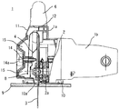
図1及び図2において、携帯用切断機1(以下、切断機と称す)は、モータ2を駆動源とする電気式のものであって、切断機本体1aに接続されたモータハウジング1bにはモータ2が横置き状態(図2の左右方向)で水平に配置されている。モータ2の出力軸2aには円板状の鋸刃3が取り付けられており、鋸刃3は、その上半部外周がソーカバー4によって覆われていると共に、下半部の一部は出力軸2aを中心として回動可能であり回動した際にソーカバー4に収納される保護カバー5によって覆われている。   1 and 2, a portable cutting machine 1 (hereinafter referred to as a cutting machine) is an electric type using a motor 2 as a drive source, and a motor housing 1b connected to a cutting machine main body 1a includes The motor 2 is horizontally arranged in the horizontal position (left and right direction in FIG. 2). A disc-shaped saw blade 3 is attached to the output shaft 2a of the motor 2, and the saw blade 3 is covered with a saw cover 4 at the outer periphery of the upper half portion, and a part of the lower half portion is an output shaft. It can be rotated around 2a and is covered with a protective cover 5 housed in the saw cover 4 when rotated.

また、切断機本体1aには、作業者が把持するためのハンドル6が設けられており、このハンドル6には、電源コード7からモータ2への通電をオン又はオフして切断機1を起動又は停止するためのスイッチ8が設けられている。   In addition, the cutting machine body 1a is provided with a handle 6 for an operator to hold. The handle 6 is activated by turning on or off the power supply from the power cord 7 to the motor 2. Alternatively, a switch 8 for stopping is provided.

更に、切断機本体1aには、加工材9上に載置される矩形プレート状のベース10が設けられており、このベース10に形成されたスリット状の挿通溝10Aを鋸刃3が貫通し、鋸刃3の一部が図1に示すようにベース10の下方に突出しすることで、鋸刃3により加工材9の切断を行なうことができるようになっている。   Further, the cutting machine main body 1 a is provided with a rectangular plate-like base 10 placed on the workpiece 9, and the saw blade 3 penetrates the slit-like insertion groove 10 </ b> A formed in the base 10. A part of the saw blade 3 protrudes below the base 10 as shown in FIG. 1 so that the workpiece 9 can be cut by the saw blade 3.

ところで、ソーカバー4には、加工材9の切断作業によって発生する粉塵(切粉)を集塵するための集塵カバー10が切断機1(ソーカバー4)に対してボルト14によって着脱可能に取り付けられている。ここで、本実施の形態では、ソーカバー4は、後述する容量可変機構を構成する集塵スリーブ12と切断機本体1aによって挟持され、集塵カバー11はソーカバー4に対して着脱可能に取り付けられている。   By the way, the dust cover 10 for collecting dust (chip) generated by the cutting operation of the workpiece 9 is detachably attached to the saw cover 4 by bolts 14 with respect to the cutting machine 1 (saw cover 4). ing. Here, in the present embodiment, the saw cover 4 is sandwiched between a dust collecting sleeve 12 and a cutting machine main body 1a constituting a variable capacity mechanism described later, and the dust collecting cover 11 is detachably attached to the saw cover 4. Yes.

以上のように構成された切断機1を用いて加工材9を切断するには、ベース10の底面を加工材9上に載置し、スイッチ8をオンして電源コード7からモータ2に電力を供給しモータ2を起動する。モータ2の回転軸2aに取り付けられた鋸刃3が回転軸2aによって図1の矢印Aの方向(図1の反時計方向)に回転駆動され、作業者がハンドル6を把持して切断機1を加工材9の表面に沿って移動させれば、回転する鋸刃3によって加工材9が切断される。加工材9の切断によって発生する粉塵は、図2の矢印Bに示すように、鋸刃3の回転に伴って発生する空気流によって上方に巻き上げられてソーカバー4内に進入し、空気流と共にソーカバー4の内周壁に沿って流れ、最終的には後述するソーカバー4と集塵カバー5とで形成された収納空間となる集塵空間15に回収されて蓄積される。なお、モータ2への電力供給を繰り返し充放電可能な電池によって行なっても良い。   In order to cut the workpiece 9 using the cutting machine 1 configured as described above, the bottom surface of the base 10 is placed on the workpiece 9, the switch 8 is turned on, and power is supplied from the power cord 7 to the motor 2. To start the motor 2. The saw blade 3 attached to the rotating shaft 2a of the motor 2 is rotationally driven in the direction of arrow A in FIG. 1 (counterclockwise in FIG. 1) by the rotating shaft 2a, and the operator holds the handle 6 and cuts the cutting machine 1 Is moved along the surface of the workpiece 9, the workpiece 9 is cut by the rotating saw blade 3. As shown by the arrow B in FIG. 2, the dust generated by cutting the workpiece 9 is wound up by the air flow generated along with the rotation of the saw blade 3 and enters the saw cover 4, and the saw cover together with the air flow. 4 is collected and accumulated in a dust collection space 15 which is a storage space formed by a saw cover 4 and a dust collection cover 5 which will be described later. In addition, you may perform the electric power supply to the motor 2 with the battery which can be charged / discharged repeatedly.

ソーカバー4と集塵カバー11により形成される粉塵の集塵空間15に粉塵が溜まると、把持部14aを把持してボルト14を緩めることによって集塵カバー11をソーカバー4から取り外して粉塵を廃棄し清掃することができる。図10に示す従来の集塵カバーを備えた切断機100では、集塵カバー101を切断方向前後に設けられた2つのボルト106によって切断機本体100Aに固定するだけであり集塵空間105が固定の大きさであった。従って、集塵カバー101(集塵空間)が大きい場合には粉塵の回収量は多くすることができるが切断機1自体が大型化してしまい作業場所によっては集塵カバー101が邪魔になり切断作業が行なえなかったり、逆に、小さい場合には粉塵の回収量が少なくなってしまい粉塵の廃棄作業を頻繁に行なうことが必要となってしまい作業効率が低下するものであった。   When dust accumulates in the dust collecting space 15 formed by the saw cover 4 and the dust collecting cover 11, the dust collecting cover 11 is detached from the saw cover 4 by holding the gripping portion 14a and loosening the bolts 14, and the dust is discarded. Can be cleaned. In the cutting machine 100 having the conventional dust collecting cover shown in FIG. 10, the dust collecting cover 101 is fixed to the cutting machine main body 100A only by the two bolts 106 provided before and after the cutting direction, and the dust collecting space 105 is fixed. It was the size of. Accordingly, when the dust collection cover 101 (dust collection space) is large, the amount of collected dust can be increased, but the cutting machine 1 itself becomes large and the dust collection cover 101 becomes an obstacle in some work places, so that the cutting work is interrupted. However, if it is small, the amount of collected dust becomes small, and it becomes necessary to frequently dispose of dust, resulting in a reduction in work efficiency.

そこで、本実施の形態では、ソーカバー4と集塵カバー11の間に形成される集塵空間の大きさ(粉塵の回収量)を変更することができるようにして、切断作業に合わせて集塵空間を調整でき作業性を向上することができるようにしている。以下、本実施の形態に係る集塵空間の調整機構について詳細に説明する。   Therefore, in the present embodiment, the size of the dust collection space (the amount of collected dust) formed between the saw cover 4 and the dust collection cover 11 can be changed, and the dust collection is performed in accordance with the cutting operation. The space can be adjusted and workability can be improved. Hereinafter, the adjustment mechanism of the dust collection space according to the present embodiment will be described in detail.

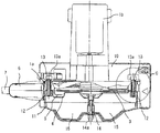
図2乃至図7に示すように、ソーカバー4と集塵カバー11との間に容量可変機構を構成し介在部材となる集塵スリーブ12を配置し、集塵スリーブ12は集塵カバー11との突き当て部12a及び12bを非対称な形状とし切断機本体1aに対し取り付け向きを変えることで集塵空間15の大きさを調整することができるようになっている。   As shown in FIGS. 2 to 7, a dust collection sleeve 12 that constitutes a variable capacity mechanism and serves as an interposition member is disposed between the saw cover 4 and the dust collection cover 11, and the dust collection sleeve 12 is connected to the dust collection cover 11. The size of the dust collection space 15 can be adjusted by making the abutting portions 12a and 12b asymmetrical and changing the mounting direction with respect to the cutting machine main body 1a.

図3に示すように、集塵スリーブ12は、切断機本体1a及びソーカバー4を貫通する把持部13aを有する蝶ボルト13を固定するための螺子部12dを有する。集塵スリーブ12の外周には、集塵スリーブ12の取り付け向きに応じてソーカバー4と当接する突き当て面12cが形成され、突き当て面12cからの距離が異なり一方が本体1aと、他方が集塵カバー11と当接する突き当て面部12a及び12bが表裏の両面に形成されている。また、集塵スリーブ12の外周には、集塵カバー11の先端部11aと係合するための溝部12eが形成されている。   As shown in FIG. 3, the dust collecting sleeve 12 has a screw portion 12 d for fixing a butterfly bolt 13 having a gripping portion 13 a that penetrates the cutting machine main body 1 a and the saw cover 4. An abutting surface 12c that abuts the saw cover 4 is formed on the outer periphery of the dust collecting sleeve 12 according to the mounting direction of the dust collecting sleeve 12, and the distance from the abutting surface 12c is different, one being the main body 1a and the other being the collecting surface. Abutting surface portions 12a and 12b that contact the dust cover 11 are formed on both the front and back surfaces. Further, on the outer periphery of the dust collecting sleeve 12, a groove portion 12 e for engaging with the tip end portion 11 a of the dust collecting cover 11 is formed.

一方、切断機本体1aの外周には、凹部1cが形成されており、集塵スリーブ12をボルト13で固定した際に突き当て面部12aが当接しないように、すなわち突き当て面部12aを回避するように形成されている。   On the other hand, a recess 1c is formed on the outer periphery of the cutting machine main body 1a so that the abutting surface portion 12a does not come into contact when the dust collecting sleeve 12 is fixed with the bolt 13, that is, the abutting surface portion 12a is avoided. It is formed as follows.

上述のように形成された集塵スリーブ12を切断機本体1aに固定する際に、突き当て面部12aと12bのいずれを集塵カバー11に突き当てるかにより、ソーカバー4と集塵カバー11の距離が変化することになり、粉塵の集塵空間15の大小が選択可能となる。   When fixing the dust collecting sleeve 12 formed as described above to the cutting machine main body 1a, the distance between the saw cover 4 and the dust collecting cover 11 depends on which of the abutting surface portions 12a and 12b abuts against the dust collecting cover 11. Changes, and the size of the dust collection space 15 can be selected.

図2乃至図4は、集塵スリーブ12の突き当て面部12bを集塵カバー111に突き当てた場合の断面図であり、集塵空間15が小さい状態であり、図5乃至図7は集塵スリーブ12の突き当て面部12aを集塵カバー11に突き当てた場合の断面図であり、集塵空間15が大きい状態を示すものである。   2 to 4 are cross-sectional views when the abutting surface portion 12b of the dust collecting sleeve 12 is abutted against the dust collecting cover 111, and the dust collecting space 15 is small. FIGS. It is sectional drawing at the time of butting | butting the abutting surface part 12a of the sleeve 12 against the dust collection cover 11, and shows the state where the dust collection space 15 is large.

まず、図2乃至図4に示した集塵空間15が小さい場合、すなわち切断作業で粉塵があまり出ない場合や作業場所が狭い場合について説明する。この場合、集塵スリーブ12を図4に示すように本体1aに取り付ける。集塵スリーブ12は略L字状になっており、把持部13aを有するボルト13によって集塵スリーブ12を本体1aに取り付ける際に、ボルト13が挿入される穴部12dが集塵スリーブ12の一部を貫通して形成されている。突き当て面部12aを本体1a側に、突き当て面部12bを集塵カバー11側に配置し、集塵スリーブ12をボルト13によって本体1aに固定する。この場合、突き当て面部12a側の突き当て面12cがソーカバー4と当接する。突き当て面部12aは本体部1aに設けられた凹部1cに入り込むように配置され固定される。一方、突き当て面部12bには、集塵カバー11が当接され、集塵カバー11の先端部11aは、集塵スリーブ12に設けられた溝部12eに入り込む。これにより、左右方向のズレを防止することができると共に、集塵カバー11の集塵スリーブ12に対する位置決めを容易に行なうことができる。突き当て面部12bの端面は、ソーカバー4と当接しない側の突き当て面12cの端面と略同じ位置に配置される。   First, a case where the dust collection space 15 shown in FIGS. 2 to 4 is small, that is, a case where dust is not generated so much by cutting work or a work place is narrow will be described. In this case, the dust collecting sleeve 12 is attached to the main body 1a as shown in FIG. The dust collecting sleeve 12 is substantially L-shaped, and when the dust collecting sleeve 12 is attached to the main body 1a with the bolt 13 having the gripping portion 13a, the hole 12d into which the bolt 13 is inserted is a part of the dust collecting sleeve 12. It is formed through the part. The abutting surface portion 12 a is disposed on the main body 1 a side, the abutting surface portion 12 b is disposed on the dust collecting cover 11 side, and the dust collecting sleeve 12 is fixed to the main body 1 a by bolts 13. In this case, the abutting surface 12 c on the abutting surface portion 12 a side comes into contact with the saw cover 4. The abutting surface portion 12a is arranged and fixed so as to enter the concave portion 1c provided in the main body portion 1a. On the other hand, the dust collecting cover 11 is brought into contact with the abutting surface portion 12b, and the tip end portion 11a of the dust collecting cover 11 enters the groove portion 12e provided in the dust collecting sleeve 12. Thereby, the horizontal displacement can be prevented, and the dust collection cover 11 can be easily positioned with respect to the dust collection sleeve 12. The end surface of the abutting surface portion 12b is disposed at substantially the same position as the end surface of the abutting surface 12c on the side that does not contact the saw cover 4.

集塵スリーブ12を本体1aに固定し、集塵カバー11を位置決めした後、ボルト14によって集塵カバー11を切断機1に固定することによって、集塵空間15が小さい切断機1を構成することができる。   After the dust collecting sleeve 12 is fixed to the main body 1a and the dust collecting cover 11 is positioned, the dust collecting cover 11 is fixed to the cutting machine 1 by bolts 14, thereby forming the cutting machine 1 having a small dust collecting space 15. Can do.

次に、図5乃至図7に示した集塵空間15が大きい場合、すなわち切断作業で粉塵が多く出る場合について説明する。この場合、集塵スリーブ12を図7に示すように本体1aに取り付ける。突き当て面部12bを本体1a側に、突き当て面部12aを集塵カバー11側に配置し、集塵スリーブ12をボルト13によって本体1aに固定する。この場合、突き当て面部12b側の突き当て面12cがソーカバー4と当接する。突き当て面部12aには、集塵カバー11が当接され、集塵カバー11の先端部11aは、突き当て面部12aの側面と当接することにより、左右方向のズレを防止することができると共に、集塵カバー11の集塵スリーブ12に対する位置決めを容易に行なうことができる。突き当て面部12aの端面は、ソーカバー4と当接しない側の突き当て面12cの端面より突き当て面12cと突き当て面部12a端面との距離X分、突き当て面12cより集塵カバー11側に突出して配置される。従って、図2乃至図4の状態に対して距離X分の集塵空間を増やすことができるため、集塵空間15を大きくすることができ、集塵効率を向上することができる。   Next, a case where the dust collection space 15 shown in FIGS. 5 to 7 is large, that is, a case where a large amount of dust is generated in the cutting operation will be described. In this case, the dust collecting sleeve 12 is attached to the main body 1a as shown in FIG. The abutting surface portion 12b is disposed on the main body 1a side, the abutting surface portion 12a is disposed on the dust collecting cover 11 side, and the dust collecting sleeve 12 is fixed to the main body 1a with bolts 13. In this case, the abutting surface 12 c on the abutting surface portion 12 b side contacts the saw cover 4. The dust collecting cover 11 is brought into contact with the abutting surface portion 12a, and the front end portion 11a of the dust collecting cover 11 is brought into contact with the side surface of the abutting surface portion 12a. The dust collection cover 11 can be easily positioned with respect to the dust collection sleeve 12. The end surface of the abutting surface portion 12a is closer to the dust collecting cover 11 side than the abutting surface 12c by the distance X between the abutting surface 12c and the abutting surface portion 12a than the end surface of the abutting surface 12c on the side not in contact with the saw cover 4. Protrusively arranged. Therefore, since the dust collection space corresponding to the distance X can be increased with respect to the states of FIGS. 2 to 4, the dust collection space 15 can be enlarged, and the dust collection efficiency can be improved.

集塵スリーブ12を本体1aに固定し、集塵カバー11を位置決めした後、ボルト14によって集塵カバー11を切断機1に固定することによって、集塵空間15が大きい切断機1を構成することができる。   The dust collecting sleeve 12 is fixed to the main body 1a, the dust collecting cover 11 is positioned, and then the dust collecting cover 11 is fixed to the cutting machine 1 with bolts 14, thereby forming the cutting machine 1 having a large dust collecting space 15. Can do.

以上から、本実施の形態では、集塵スリーブ12を切断機本体1aに対し、表裏のどちら側でも固定可能としたため、集塵カバー11と当接する突き当て面部12a及び12bのどちらか一方を選択し固定することができる。この突き当て面部の選択により、切断機本体1aから集塵カバー11までの距離を変化させることが可能となり、粉塵を蓄積する集塵空間15の大きさを容易に変更することができる。   From the above, in the present embodiment, since the dust collecting sleeve 12 can be fixed to the cutting machine body 1a on either the front or back side, either one of the abutting surface portions 12a and 12b contacting the dust collecting cover 11 is selected. Can be fixed. By selecting the abutting surface portion, the distance from the cutting machine main body 1a to the dust collecting cover 11 can be changed, and the size of the dust collecting space 15 for accumulating dust can be easily changed.

従って、本実施の形態によれば、集塵スリーブ12を表裏に付け変えることにより、粉塵を蓄積する集塵空間15を容易に変化させることができるため、作業効率を向上することができる。
<実施の形態2>
次に、本発明の第2の実施の形態について図8及び図9に基づいて説明する。
Therefore, according to the present embodiment, the dust collection space 15 in which the dust is accumulated can be easily changed by attaching the dust collection sleeve 12 to the front and back, so that the work efficiency can be improved.
<Embodiment 2>
Next, a second embodiment of the present invention will be described with reference to FIGS.

図8は本発明の実施の形態に係る携帯用切断機1の集塵カバー11の固定状態を示す断面図、図9は本体1aに対して集塵カバー11の取り付け位置を変更した場合の図8のD部拡大図であり、これらの図においては図1乃至図7に示したものと同一の機能を有するものには同一符号を付しており、以下それらについての説明は省略する。   FIG. 8 is a cross-sectional view showing a fixed state of the dust collecting cover 11 of the portable cutting machine 1 according to the embodiment of the present invention, and FIG. 9 is a diagram when the attachment position of the dust collecting cover 11 is changed with respect to the main body 1a. FIG. 8 is an enlarged view of a portion D. In these drawings, the same reference numerals are given to the components having the same functions as those shown in FIGS. 1 to 7, and description thereof will be omitted below.

本実施の形態に係る切断機1の基本構成は第1の実施の形態と同じであるが、集塵カバー11の集塵空間15の調整機構を変更した点が異なっており、第1の実施の形態の集塵スリーブ12を削除し、代わりに操作レバー16によって集塵空間15を調整する構成としたものである。   The basic configuration of the cutting machine 1 according to the present embodiment is the same as that of the first embodiment, except that the adjustment mechanism of the dust collection space 15 of the dust collection cover 11 is changed. The dust collecting sleeve 12 of the form is deleted, and the dust collecting space 15 is adjusted by the operation lever 16 instead.

ソーカバー4は切断機本体1aに固定されており、集塵スリーブ12及びボルト14は使用せず、代わりに容量可変機構をスライド部で構成し集塵カバー11を直接、操作レバー16によって切断機本体1aに固定する構成とした。具体的には、切断機本体1aには、集塵カバー11との係合部16aを有する操作レバー16が、軸17を介して回動可能に設けられており、操作レバー16は切断機本体1aに縮装されたバネ等からなる弾性体18により係合部16aを集塵カバー11に付勢するように配置されている。なお、スライド部は、操作レバー16、軸17、弾性体18、及び後述する凹部11bを含む。   The saw cover 4 is fixed to the cutting machine main body 1 a, and the dust collecting sleeve 12 and the bolt 14 are not used. Instead, the capacity variable mechanism is configured by a slide part, and the dust collecting cover 11 is directly operated by the operation lever 16. It was set as the structure fixed to 1a. Specifically, the cutting machine main body 1a is provided with an operation lever 16 having an engagement portion 16a with the dust collecting cover 11 so as to be rotatable via a shaft 17. The operation lever 16 is provided with the cutting machine main body 1a. The engaging portion 16a is arranged to be urged to the dust collecting cover 11 by an elastic body 18 composed of a spring or the like that is contracted to 1a. The slide portion includes an operation lever 16, a shaft 17, an elastic body 18, and a concave portion 11b described later.

一方、集塵カバー11には、操作レバー16の係合部16aと係合し、集塵カバー11と切断機本体1aを固定するための凹部11bが複数個形成されている。 集塵カバー11の全周には、切断機本体1a及びソーカバー4側に伸長する外周壁11cが形成され、一方の切断機本体1a及びソーカバー4を包み込むよう構成される。また、集塵カバー11と切断機本体1a及びソーカバー4との間に発生する隙間から、粉塵が漏れるのを防止するためのシール部材19が設けられてる。   On the other hand, the dust collecting cover 11 is formed with a plurality of recesses 11b that engage with the engaging portion 16a of the operation lever 16 and fix the dust collecting cover 11 and the cutting machine body 1a. An outer peripheral wall 11c extending toward the cutting machine main body 1a and the saw cover 4 is formed on the entire circumference of the dust collecting cover 11, and is configured to wrap around the one cutting machine main body 1a and the saw cover 4. Further, a seal member 19 is provided for preventing dust from leaking from a gap generated between the dust collecting cover 11 and the cutting machine main body 1a and the saw cover 4.

本実施の形態において、図8に示すように集塵カバー11が切断機本体1aに取り付けられた状態では、操作レバー16の係合部16aが切断機本体1aの凹部11bに係合するように弾性体18により付勢されているため、集塵カバー11が切断機本体1aに確実に固定されており、集塵カバー11が切断機本体1aから外れることはない。   In the present embodiment, as shown in FIG. 8, when the dust cover 11 is attached to the cutting machine main body 1a, the engaging portion 16a of the operating lever 16 is engaged with the recess 11b of the cutting machine main body 1a. Since the elastic body 18 is biased, the dust collecting cover 11 is securely fixed to the cutting machine main body 1a, and the dust collecting cover 11 does not come off the cutting machine main body 1a.

集塵カバー11が切断機本体1aに固定された状態から集塵カバー11を取り外すには、作業者は操作レバー16の操作部16bを操作して操作レバー16を、軸17を中心として弾性体18に抗して押すことにより、係合部16aと凹部11bの係合が解除されるため、集塵カバー11と切断機本体1aの位置を変更することができ、第1の実施の形態と同様に粉塵を蓄積する集塵空間15の大きさを容易に変化させることができる。集塵空間15の容量変更の手順を図9を用いて具体的に説明する。   In order to remove the dust collection cover 11 from the state in which the dust collection cover 11 is fixed to the cutting machine main body 1a, the operator operates the operation portion 16b of the operation lever 16 to move the operation lever 16 around the shaft 17 as an elastic body. Since the engagement between the engaging portion 16a and the concave portion 11b is released by pushing against 18, the positions of the dust collecting cover 11 and the cutting machine main body 1a can be changed. Similarly, the size of the dust collection space 15 for accumulating dust can be easily changed. The procedure for changing the capacity of the dust collection space 15 will be specifically described with reference to FIG.

図9(a)が通常の状態とする。この状態では集塵空間15は最も小さい容量に設定されている。この状態から同図(b)に示す矢印Yの方向に操作レバー16の操作部16bを弾性体18の付勢力に抗して押すことにより、操作レバー16は軸17を中心に回転し、係合部16aが集塵カバー11の凹部11bから外れる。その後、同図(c)に示すように、集塵カバー11を矢印Zの方向にスライドさせ、係合部16aを集塵カバー11に設けた複数の凹部11bの内、切断作業に応じた凹部11bと係合させる。すなわち、操作部16bに掛ける押圧力を解除し、操作レバー16を弾性体18の付勢力により軸17を中心に回転させ、凹部11bと係合部16aを係合させることによって、集塵カバー11の集塵空間15の容量を変更することができ、切断作業に応じて適切な集塵容量を確保することができ、作業性を向上することができる。また、本実施の形態では、操作レバー16によって、係合部16aと凹部11bとの係合及び係合解除を行なうようにしたため、集塵空間15の容量を容易に変更することができ操作性も向上することができる。   FIG. 9A shows a normal state. In this state, the dust collection space 15 is set to the smallest capacity. From this state, by pushing the operating portion 16b of the operating lever 16 against the urging force of the elastic body 18 in the direction of the arrow Y shown in FIG. The joining portion 16a is detached from the concave portion 11b of the dust collecting cover 11. Thereafter, as shown in FIG. 5C, the dust collection cover 11 is slid in the direction of arrow Z, and the engagement portion 16a is a recess corresponding to the cutting operation among the plurality of recesses 11b provided in the dust collection cover 11. Engage with 11b. That is, the pressure applied to the operation portion 16b is released, the operation lever 16 is rotated around the shaft 17 by the urging force of the elastic body 18, and the concave portion 11b and the engagement portion 16a are engaged with each other, thereby collecting the dust collecting cover 11. The capacity of the dust collection space 15 can be changed, an appropriate dust collection capacity can be ensured according to the cutting work, and workability can be improved. In the present embodiment, since the engaging portion 16a and the recessed portion 11b are engaged and disengaged by the operation lever 16, the capacity of the dust collection space 15 can be easily changed and the operability is improved. Can also be improved.

なお、集塵カバー11と切断機本体1aの固定をより強固なものとするために、図9の固定部を複数個設けることや、第1の実施の形態と同様に集塵カバー11をボルト14によりソーカバー4に固定する方法との併用を実施することができる。   In order to make the dust cover 11 and the cutting machine main body 1a fixed more firmly, a plurality of fixing portions shown in FIG. 9 are provided, or the dust cover 11 is bolted as in the first embodiment. 14 can be used together with the method of fixing to the saw cover 4.

従って、本実施の形態においても、操作性良く集塵カバー11の位置を変更することができ、粉塵を蓄積する集塵空間を容易に変化させることができる。また、集塵カバー11の固定を解除し、集塵カバー11を切断機本体1aから操作性良く取り外すことが可能であり、粉塵の廃棄及び集塵カバー等の清掃を容易に行なうことができる。   Therefore, also in the present embodiment, the position of the dust collection cover 11 can be changed with good operability, and the dust collection space for accumulating dust can be easily changed. In addition, the dust cover 11 can be released and the dust cover 11 can be removed from the cutting machine main body 1a with good operability, and dust can be discarded and the dust cover can be easily cleaned.

本発明は、第1の実施の形態では、集塵スリーブ12を介して集塵カバー11を本体1aにボルト14によって固定し、集塵スリーブ12の取り付け方向を変えることによって集塵空間15の容量を変更するようにした構成とし、第2の実施の形態では、集塵カバー11に複数の凹部11bを設け、本体1aに設けた操作レバー16の操作によって凹部11bと係止部16aとの係合及び係合解除を行なうことによって集塵空間15の容量を変更するようにした構成とした。このような構成にすることによって、切断作業に応じて集塵空間の容量を容易に変更することができ、作業性及び操作性を向上することができる。また、本発明は、上記実施の形態に係らず、集塵空間の容量を変更できるようにすることを特徴とするものであり、種々の変更が可能である。   In the first embodiment, the capacity of the dust collection space 15 is determined by fixing the dust collection cover 11 to the main body 1a with the bolt 14 via the dust collection sleeve 12 and changing the mounting direction of the dust collection sleeve 12. In the second embodiment, the dust collection cover 11 is provided with a plurality of recesses 11b, and the operation lever 16 provided on the main body 1a is operated to operate the engagement between the recesses 11b and the locking portions 16a. The capacity of the dust collection space 15 is changed by performing engagement and disengagement. With such a configuration, the capacity of the dust collection space can be easily changed according to the cutting work, and workability and operability can be improved. Further, the present invention is characterized in that the capacity of the dust collection space can be changed regardless of the above embodiment, and various changes can be made.

本発明の第1の実施の形態に係る携帯用切断機の側面図である。It is a side view of the portable cutting machine which concerns on the 1st Embodiment of this invention. 集塵空間の容量を小さくした状態を示す図1のA−A断面図である。It is AA sectional drawing of FIG. 1 which shows the state which made the capacity | capacitance of dust collection space small. 集塵空間の容量を小さくした状態を示す図1のB−B断面図である。It is BB sectional drawing of FIG. 1 which shows the state which made the capacity | capacitance of dust collection space small. 図3のC部拡大断面図である。It is the C section expanded sectional view of FIG. 本発明の第1の実施の形態に係る集塵空間の容量を大きくした状態を示す図1のA−A断面図である。It is AA sectional drawing of FIG. 1 which shows the state which enlarged the capacity | capacitance of the dust collection space which concerns on the 1st Embodiment of this invention. 集塵空間の容量を大きくした状態を示す図1のB−B断面図である。It is BB sectional drawing of FIG. 1 which shows the state which enlarged the capacity | capacitance of dust collection space. 図6のC部拡大断面図である。It is the C section expanded sectional view of FIG. 本発明の第2の実施の形態に係る携帯用切断機の断面図である。It is sectional drawing of the portable cutting machine which concerns on the 2nd Embodiment of this invention. 図8のD部拡大断面図である。It is the D section expanded sectional view of FIG. 従来の携帯用切断機の上面断面図である。It is an upper surface sectional view of the conventional portable cutting machine.

符号の説明Explanation of symbols

1は携帯用切断機、1aは切断機本体、2はモータ、3は鋸刃、4はソーカバー、5は保護カバー、6はハンドル、7は電源コード、8はスイッチ、9は加工材、10はベース、11は集塵カバー、12は集塵スリーブ、12a及び12bは突き当て面部、12cはソーカバー突き当て面、13は蝶ボルト、14は着脱ボルト、15は集塵空間、16は操作レバー、16aは係合部、16bは操作部である。   1 is a portable cutting machine, 1a is a cutting machine body, 2 is a motor, 3 is a saw blade, 4 is a saw cover, 5 is a protective cover, 6 is a handle, 7 is a power cord, 8 is a switch, 9 is a workpiece, 10 Is a base, 11 is a dust collecting cover, 12 is a dust collecting sleeve, 12a and 12b are abutting surface portions, 12c is a saw cover abutting surface, 13 is a butterfly bolt, 14 is a detachable bolt, 15 is a dust collecting space, and 16 is an operating lever. 16a is an engaging portion, and 16b is an operating portion.

Claims (7)

回転軸を有するモータと、
該モータの回転軸に取り付けられて回転する鋸刃と、
該鋸刃の外周の一部を覆うソーカバーと、
該ソーカバーに着脱可能に取り付けられ粉塵を収納する集塵カバーと、を備えた本体を有する携帯用切断機において、
前記集塵カバーの前記ソーカバーに対する取り付け状態を変えることで、前記ソーカバーと前記集塵カバーとによって構成される前記粉塵を収納する収納空間の大きさを変更可能にしたことを特徴とする携帯用切断機。
A motor having a rotating shaft;
A saw blade attached to the rotating shaft of the motor and rotating;
A saw cover covering a part of the outer periphery of the saw blade;
In a portable cutting machine having a main body provided with a dust collection cover that is detachably attached to the saw cover and stores dust,
A portable cutting device characterized in that a size of a storage space for storing the dust constituted by the saw cover and the dust collection cover can be changed by changing an attachment state of the dust collection cover to the saw cover. Machine.
前記ソーカバーと集塵カバーとの間に介在部材を有し、該介在部材の前記本体に対する取り付け向きを変えることにより、前記収納空間の容量を変更可能としたことを特徴とする請求項1記載の携帯用切断機。   The interposition member is provided between the saw cover and the dust collection cover, and the capacity of the storage space can be changed by changing the mounting direction of the interposition member with respect to the main body. Portable cutting machine. 前記介在部材は、本体に対する取り付け向きを変えることにより、前記ソーカバーに当接する面から前記集塵カバーに当接する面までの距離が異なることを特徴とする請求項2記載の携帯用切断機。   The portable cutting machine according to claim 2, wherein the interposition member has a different distance from a surface that contacts the saw cover to a surface that contacts the dust collecting cover by changing an attachment direction with respect to the main body. 前記集塵カバーを前記本体に対して前記回転軸の軸方向にスライド可能に配置したスライド部を有することを特徴とする請求項1記載の携帯用切断機。   The portable cutting machine according to claim 1, further comprising a slide portion that is slidably disposed in the axial direction of the rotation shaft with respect to the main body. 前記スライド部は、前記本体もしくは前記集塵カバーの一方に設けた操作レバーと、他方に設けられ該操作レバーの一端部が係合する係合溝と、前記操作レバーの一端部を前記係合溝に係合するように前記操作レバーの他端部を付勢する弾性体とを備えたことを特徴とする請求項4記載の携帯用切断機。   The slide portion includes an operation lever provided on one of the main body or the dust collecting cover, an engagement groove provided on the other side and engaged with one end of the operation lever, and one end of the operation lever engaged with the slide. The portable cutting machine according to claim 4, further comprising an elastic body that biases the other end of the operation lever so as to engage with the groove. 前記係合溝は、前記本体もしくは前記集塵カバーの前記回転軸の軸方向に複数箇所設けられていることを特徴とする請求項5記載の携帯用切断機。   The portable cutting machine according to claim 5, wherein the engagement groove is provided at a plurality of positions in an axial direction of the rotation shaft of the main body or the dust collecting cover. 前記集塵カバーと前記本体との間にシール部材を設けたことを特徴とする請求項4乃至請求項6のいずれかに記載の携帯用切断機。   The portable cutting machine according to any one of claims 4 to 6, wherein a seal member is provided between the dust collecting cover and the main body.
JP2008235419A 2008-09-12 2008-09-12 Portable cutting machine Expired - Fee Related JP5115415B2 (en)

Priority Applications (1)

Application Number Priority Date Filing Date Title
JP2008235419A JP5115415B2 (en) 2008-09-12 2008-09-12 Portable cutting machine

Applications Claiming Priority (1)

Application Number Priority Date Filing Date Title
JP2008235419A JP5115415B2 (en) 2008-09-12 2008-09-12 Portable cutting machine

Publications (2)

Publication Number Publication Date
JP2010064226A JP2010064226A (en) 2010-03-25
JP5115415B2 true JP5115415B2 (en) 2013-01-09

Family

ID=42190259

Family Applications (1)

Application Number Title Priority Date Filing Date
JP2008235419A Expired - Fee Related JP5115415B2 (en) 2008-09-12 2008-09-12 Portable cutting machine

Country Status (1)

Country Link
JP (1) JP5115415B2 (en)

Families Citing this family (6)

* Cited by examiner, † Cited by third party
Publication number Priority date Publication date Assignee Title
EP2605878B1 (en) * 2010-08-18 2021-01-20 Cuz-D Manufacturing, Inc., dba Cuzdey R&D Convertible zero clearance circular saw
JP5713822B2 (en) * 2010-10-04 2015-05-07 株式会社マキタ Tabletop circular saw
USD802391S1 (en) 2016-05-23 2017-11-14 Cuz-D Manufacturing, Inc. Arbor for a circular saw
USD819419S1 (en) 2016-05-23 2018-06-05 Cuz-D Manufacturing, Inc. Circular saw blade
USD802393S1 (en) 2016-05-23 2017-11-14 Cuz-D Manufacturing, Inc. Circular saw blade
USD802392S1 (en) 2016-05-23 2017-11-14 Cuz-D Manufacturing, Inc. Circular saw blade

Family Cites Families (4)

* Cited by examiner, † Cited by third party
Publication number Priority date Publication date Assignee Title
JPS581511U (en) * 1981-06-26 1983-01-07 富士写真フイルム株式会社 Protection device for power-driven rotary blades
DE4224094A1 (en) * 1992-07-22 1994-01-27 Bosch Gmbh Robert Hand saw with suction device
JP4045079B2 (en) * 2000-08-02 2008-02-13 仲山鉄工株式会社 Sludge water recovery processing method for cutting equipment for concrete and the like, and water storage tank used therefor
JP3899224B2 (en) * 2000-08-10 2007-03-28 株式会社マキタ Circular saw machine

Also Published As

Publication number Publication date
JP2010064226A (en) 2010-03-25

Similar Documents

Publication Publication Date Title
JP5115415B2 (en) Portable cutting machine
EP2361732B1 (en) Power tool having off-lock member
JP4466771B2 (en) Electric circular saw
JP2009061741A (en) Portable cutter
JP2008207288A (en) Power tool
US20070034064A1 (en) Dust-collecting unit and electric tool having the same
JP4957228B2 (en) cutter
JP2015044244A (en) Cutting tool
JP5056216B2 (en) Drilling tool
JP6300562B2 (en) Work tools
JP5239334B2 (en) Portable cutting machine
JP5017187B2 (en) Power tool
JP2008207360A (en) Power tool with dust collection mechanism
JP6464017B2 (en) Polishing machine
JP5465556B2 (en) Dust collection structure of cutting tool
WO2011086736A1 (en) Cutting machine
JP4795097B2 (en) Cutting machine
JP4954489B2 (en) Pipe cutting machine
JP2017221986A (en) Dust collector and working tool
JP5376397B2 (en) Protective cover and power tool with protective cover
JP2010063808A (en) Portable cutter
JP4626588B2 (en) Portable router
CN211249528U (en) Hand-held tool and cover body thereof
JP2023005977A (en) work machine
JP5082728B2 (en) Electric tool

Legal Events

Date Code Title Description
A621 Written request for application examination

Free format text: JAPANESE INTERMEDIATE CODE: A621

Effective date: 20101224

TRDD Decision of grant or rejection written
A01 Written decision to grant a patent or to grant a registration (utility model)

Free format text: JAPANESE INTERMEDIATE CODE: A01

Effective date: 20120918

A01 Written decision to grant a patent or to grant a registration (utility model)

Free format text: JAPANESE INTERMEDIATE CODE: A01

A977 Report on retrieval

Free format text: JAPANESE INTERMEDIATE CODE: A971007

Effective date: 20120920

A61 First payment of annual fees (during grant procedure)

Free format text: JAPANESE INTERMEDIATE CODE: A61

Effective date: 20121001

R150 Certificate of patent or registration of utility model

Free format text: JAPANESE INTERMEDIATE CODE: R150

FPAY Renewal fee payment (event date is renewal date of database)

Free format text: PAYMENT UNTIL: 20151026

Year of fee payment: 3

LAPS Cancellation because of no payment of annual fees