JP5115084B2 - Proximity sensor - Google Patents
Proximity sensor Download PDFInfo
- Publication number
- JP5115084B2 JP5115084B2 JP2007206308A JP2007206308A JP5115084B2 JP 5115084 B2 JP5115084 B2 JP 5115084B2 JP 2007206308 A JP2007206308 A JP 2007206308A JP 2007206308 A JP2007206308 A JP 2007206308A JP 5115084 B2 JP5115084 B2 JP 5115084B2
- Authority
- JP
- Japan
- Prior art keywords
- proximity sensor
- coil
- detection coil
- detection
- cylindrical portion
- Prior art date
- Legal status (The legal status is an assumption and is not a legal conclusion. Google has not performed a legal analysis and makes no representation as to the accuracy of the status listed.)
- Active
Links
Images


Description
本発明は近接センサに関し、特に、検出コイルおよび補助コイルを備える近接センサに関する。 The present invention relates to a proximity sensor, and more particularly to a proximity sensor including a detection coil and an auxiliary coil.
近接センサ(スイッチ)とは、検出対象の移動や存在を検出して、検出結果を電気信号として出力するセンサの総称である。検出結果を電気信号に置き換えるための検出方式には、たとえば電磁誘導により検出対象となる金属体の表面に発生する渦電流を利用する方式がある。 The proximity sensor (switch) is a general term for sensors that detect the movement or presence of a detection target and output the detection result as an electrical signal. As a detection method for replacing the detection result with an electric signal, for example, there is a method using an eddy current generated on the surface of a metal body to be detected by electromagnetic induction.
金属体の表面に渦電流を発生させるためには、金属体に鎖交する磁束を時間的に変動させる必要がある。上記した検出方式を採用する近接センサは、一般的にその磁界を生じさせるためのコイル(以下では「検出コイル」と呼ぶ)を備えている。 In order to generate an eddy current on the surface of the metal body, it is necessary to temporally change the magnetic flux linked to the metal body. Proximity sensors that employ the above-described detection method generally include a coil (hereinafter referred to as “detection coil”) for generating the magnetic field.
また、検出コイルだけでなく、検出コイルの磁界を調整するための磁界を生じさせるコイル(以下、このコイルを「補助コイル」と呼ぶ)も備える近接センサが提案されている。たとえば特許第2603628号公報(特許文献1)には、検出コイルを配備したコアの検出両端部の外周に補助コイルを巻回配備したセンサ部を有する高周波発振形近接スイッチが開示されている。この近接スイッチでは、検出コイルはポット形状のコアに挿入され、補助コイルは、E形コアの外側に設けられた補助コイルケースに巻回配備されている。補助コイルと検出コイルとは相互インダクタンスが負になるように直列に接続され、補助コイルの磁束と、センサ部装着壁面近傍に金属が存在する場合に、この金属へ漏洩する検出コイルの漏洩磁束とを鎖交させる。これにより大きな径のセンサ部を装着する装着部材が金属体であっても、漏洩磁束による検出距離への影響を回避することができる。 In addition, a proximity sensor that includes not only a detection coil but also a coil that generates a magnetic field for adjusting the magnetic field of the detection coil (hereinafter, this coil is referred to as an “auxiliary coil”) has been proposed. For example, Japanese Patent No. 2603628 (Patent Document 1) discloses a high-frequency oscillation type proximity switch having a sensor portion in which an auxiliary coil is wound around the outer periphery of both ends of a detection core. In this proximity switch, the detection coil is inserted into a pot-shaped core, and the auxiliary coil is wound around an auxiliary coil case provided outside the E-shaped core. The auxiliary coil and the detection coil are connected in series so that the mutual inductance is negative, and the magnetic flux of the auxiliary coil and the leakage magnetic flux of the detection coil that leaks to the metal when a metal exists near the sensor mounting wall surface Interlink. Thereby, even if the mounting member for mounting the sensor portion having a large diameter is a metal body, the influence on the detection distance due to the leakage magnetic flux can be avoided.
また、特表2002−519903号公報(特許文献2)には、2つの巻線を備える近接センサにおいて、2つの巻線間の相互磁束が各巻線に特有な磁束よりも十分弱くなるように、2つの巻線が配置されることが開示されている。これにより、近接センサの感度の温度による変動を抑制することができる。2つの巻線のうち一方はフェライトのポットに配置されたコイルであり、他方は、コイル枠として機能する絶縁材料のケージの中に配置される。
上記文献に開示される近接センサでは、検出コイルがコアに装着され、補助コイルがコア以外の部材(たとえばボビン等)に装着される。しかしながらこのような構成を採用した近接センサにおいては以下のような問題が発生する。 In the proximity sensor disclosed in the above document, the detection coil is attached to the core, and the auxiliary coil is attached to a member other than the core (such as a bobbin). However, the following problems occur in the proximity sensor employing such a configuration.
たとえば円柱ねじ形状近接センサにおいては、ケース体側面にねじが形成されているが、このねじのサイズはある大きさに規定されている(たとえばJIS C 8201−5−2を参照)。このため、ケース体の径の大きさを変えずにボビンをコアの外周に装着するためには、コアの径を小さくしなければならない。しかしながらコアの径を小さくすることによって検出コイルの直径も小さくなる。この場合、近接センサの検出感度が低下するという課題が発生する。 For example, in a cylindrical screw-shaped proximity sensor, a screw is formed on the side surface of the case body, and the size of this screw is defined to be a certain size (see, for example, JIS C 8201-5-2). For this reason, in order to mount the bobbin on the outer periphery of the core without changing the diameter of the case body, the diameter of the core must be reduced. However, by reducing the core diameter, the detection coil diameter is also reduced. In this case, the problem that the detection sensitivity of a proximity sensor falls arises.
また、ボビンとコアとの相対的な位置がばらつくことによって、製品ごとに特性のばらつきが発生する可能性がある。さらに、この特性ばらつきを防ぐためには、ボビンとコアとの相対的な位置のずれが小さくなるように近接センサを組立てなければならないが、これにより製造コストが上昇することが考えられる。 In addition, variations in the relative positions of the bobbin and the core may cause variations in characteristics from product to product. Furthermore, in order to prevent this characteristic variation, the proximity sensor must be assembled so that the relative displacement between the bobbin and the core is reduced, which may increase the manufacturing cost.
さらに、コアの外側に補助コイルが設けられているため、補助コイルによる磁束分布の広がりを抑制することは容易ではない。補助コイルの作る磁束の広がりが抑制されると、センサ側方への補助コイルの漏洩磁束、すなわち取付金属(周囲金属)に鎖交する磁束が低減され、磁気シールド効果が得られる。これにより検出対象に向けて検出コイルからの磁束を集中させることが可能になるので検出感度を高めることができる。しかし、補助コイルによる磁束分布の広がりを十分に抑制できない場合には、十分な磁気シールド効果を得ることができないために検出感度をより高めることができない。 Furthermore, since the auxiliary coil is provided outside the core, it is not easy to suppress the spread of the magnetic flux distribution due to the auxiliary coil. When the spread of the magnetic flux produced by the auxiliary coil is suppressed, the leakage magnetic flux of the auxiliary coil to the side of the sensor, that is, the magnetic flux interlinking with the mounting metal (surrounding metal) is reduced, and a magnetic shielding effect is obtained. As a result, the magnetic flux from the detection coil can be concentrated toward the detection target, so that the detection sensitivity can be increased. However, when the spread of the magnetic flux distribution due to the auxiliary coil cannot be sufficiently suppressed, a sufficient magnetic shield effect cannot be obtained, so that the detection sensitivity cannot be further increased.
補助コイルによる磁束分布の広がりを抑えるための方法として、たとえば補助コイルの外側に高透磁率の部材を追加することが考えられる。しかしこの場合には、コストが上昇するという課題が発生する。 As a method for suppressing the spread of the magnetic flux distribution by the auxiliary coil, for example, it is conceivable to add a member having a high magnetic permeability outside the auxiliary coil. However, in this case, there is a problem that the cost increases.
本発明はこれらの課題を解決するためになされたものであって、その目的は、検出コイルおよび補助コイルを備える近接センサにおいて、検出感度の向上およびコスト低減を可能にすることである。 The present invention has been made to solve these problems, and an object of the present invention is to enable improvement in detection sensitivity and cost reduction in a proximity sensor including a detection coil and an auxiliary coil.
本発明は要約すれば、磁界を利用して金属体の有無または位置を検出する近接センサであって、検出コイルと、コアと、補助コイルとを備える。検出コイルは、磁界を発生させる。コアは、筒状部と、筒状部の一方端を塞ぐ底部と、筒状部の外表面に設けられる鍔部とを含み、かつ、筒状部の中に検出コイルを収納する。補助コイルは、筒状部の外表面における筒状部の他方端から鍔部までの部分に直接的に巻回され、かつ、検出コイルから発生される磁界の方向を調整する磁界を発生させる。 In summary, the present invention is a proximity sensor that detects the presence or position of a metal body using a magnetic field, and includes a detection coil, a core, and an auxiliary coil. The detection coil generates a magnetic field. The core includes a tubular portion, a bottom portion that closes one end of the tubular portion, and a flange provided on the outer surface of the tubular portion, and houses the detection coil in the tubular portion. The auxiliary coil is directly wound around a portion from the other end of the cylindrical portion to the flange portion on the outer surface of the cylindrical portion, and generates a magnetic field that adjusts the direction of the magnetic field generated from the detection coil.
好ましくは、筒状部の外表面を基準とした場合に、鍔部の高さは、補助コイルの高さよりも大きい。 Preferably, when the outer surface of the cylindrical portion is used as a reference, the height of the collar portion is larger than the height of the auxiliary coil.
より好ましくは、検出コイルは、自己の形状を保つように固められた状態で筒状部の内部に収納される。コアは、底部に接続され、かつ検出コイルが通される中軸部をさらに含む。 More preferably, the detection coil is housed inside the cylindrical portion in a state of being hardened so as to maintain its own shape. The core further includes a central shaft portion connected to the bottom portion and through which the detection coil is passed.
さらに好ましくは、筒状部、底部、鍔部、および中軸部は、一体的に形成される。
さらに好ましくは、コアは、筒状部と鍔部とを一体化した部品と、底部と中軸部とを一体化した部品とを含む。
More preferably, the cylindrical portion, the bottom portion, the flange portion, and the central shaft portion are integrally formed.
More preferably, the core includes a component in which the cylindrical portion and the flange portion are integrated, and a component in which the bottom portion and the central shaft portion are integrated.
さらに好ましくは、近接センサは、検出コイルが巻回されたスプールをさらに備える。検出コイルは、スプールとともに筒状部内部に収納される。 More preferably, the proximity sensor further includes a spool around which the detection coil is wound. The detection coil is housed inside the cylindrical portion together with the spool.
さらに好ましくは、近接センサは、検出コイルにパルス状の励磁電流を周期的に流し、励磁電流の遮断後に発生する金属体の周囲の磁界変化によって検出コイルに誘起される電圧を所定の閾値と比較することにより、金属体の有無を検出する。 More preferably, the proximity sensor periodically applies a pulsed excitation current to the detection coil, and compares a voltage induced in the detection coil by a magnetic field change around the metal body generated after the excitation current is cut off with a predetermined threshold value. By doing this, the presence or absence of a metal body is detected.
本発明によれば、近接センサの検出感度の向上およびコスト低減が可能になる。 According to the present invention, it is possible to improve the detection sensitivity of the proximity sensor and reduce the cost.
以下において、本発明の実施の形態について図面を参照しつつ説明する。以下の説明では、同一の部品には同一の符号を付してある。それらの名称および機能も同じである。したがって、それらについては詳細な説明は繰り返さない。 Hereinafter, embodiments of the present invention will be described with reference to the drawings. In the following description, the same parts are denoted by the same reference numerals. Their names and functions are also the same. Therefore, detailed description thereof will not be repeated.
[実施の形態1]
図1は、本発明の実施の形態1における近接センサの構造を示す模式断面図である。また、図2は、図1に示す近接センサの組付け構造を示す分解斜視図である。まず、これら図1および図2を参照して、本実施の形態における近接センサの構造について説明する。
[Embodiment 1]
FIG. 1 is a schematic cross-sectional view showing the structure of the proximity sensor according to Embodiment 1 of the present invention. FIG. 2 is an exploded perspective view showing the assembly structure of the proximity sensor shown in FIG. First, the structure of the proximity sensor in the present embodiment will be described with reference to FIG. 1 and FIG.
図1および図2に示すように、本実施の形態における近接センサ100は、略円柱状の外形を有しており、円筒状のケース体110と、ケース体110の内部においてケース体110の前方端に取付けられた検出部組立体120と、ケース体110の内部においてケース体110の後方端に取付けられた出力部組立体130とを主に備えている。検出部組立体120は、検出コイル121、補助コイル122、フェライトコア123A、コイルケース124、検出回路基板125、および一次注型樹脂層126などを含んでいる。ここで、一次注型樹脂層126は、検出コイル121、補助コイル122およびフェライトコア123Aからなるコイル組立体と、このコイル組立体に接続された検出回路基板125とを、コイルケース124の内部において固定するための部材であり、溶融樹脂をコイルケース124内に充填して硬化させることによって形成される層である。また、出力部組立体130は、出力回路基板131を含んでいる。
As shown in FIGS. 1 and 2, the
ケース体110の前方端に取付けられた検出部組立体120の検出回路基板125と、ケース体110の後方端に取付けられた出力部組立体130の出力回路基板131とは、接続部材140によって接続されている。本実施の形態における近接センサ100にあっては、検出回路基板125および出力回路基板131がいずれもリジッド配線基板によって形成されており、接続部材140がフレキシブル配線基板にて形成されている。
The
ここで、リジッド配線基板とは、ガラス−エポキシ基板に代表されるような高い剛性を有した配線基板のことであり、電子部品の実装に適したものである。一方、フレキシブル配線基板とは、リジッド配線基板に比べて可撓性に優れた配線基板のことであり、たとえばポリイミド樹脂からなる基材の主表面に導体パターンが接着剤等によって貼り付けられて形成された配線基板のことである。このフレキシブル配線基板は、適度に可撓性を有しているため、自在に折り曲げたり折り返したりすることが可能であり、離間配置されたリジッド配線基板の導体パターン同士の接続を中継する配線基板として利用可能なものである。 Here, the rigid wiring board is a wiring board having high rigidity such as a glass-epoxy board, and is suitable for mounting electronic components. On the other hand, a flexible wiring board is a wiring board that is more flexible than a rigid wiring board. For example, a conductive pattern is bonded to the main surface of a base material made of polyimide resin with an adhesive or the like. It is a printed wiring board. Since this flexible wiring board is moderately flexible, it can be bent or folded back freely. As a wiring board that relays the connection between the conductive patterns of the rigid wiring boards that are spaced apart from each other. It is available.
ケース体110は、金属ケース111と樹脂ケース112とを含んでおり、金属ケース111の後方端に樹脂ケース112を圧入することによって構成されている。樹脂ケース112の後端面には、スリット状の開口部113が形成されており、この開口部113を貫通するように、出力回路基板131の後端部が挿通配置されている。すなわち、本実施の形態における近接センサ100にあっては、金属ケース111と樹脂ケース112とによってケース体110が構成されており、このケース体110の後端部に設けられた開口部113内に配線部材としての出力回路基板131が挿通配置されている。
The
ケース体110の外方に位置する部分の出力回路基板131には、外部接続用コード150の端子が半田付けによって接合されている。ケース体110の後端部には、出力回路基板131と外部接続用コード150との半田接合部を覆うように、インサート成形によって外側樹脂封止層としてのコードプロテクタ160が設けられている。また、ケース体110の内部の空間は、内側樹脂封止層としての二次注型樹脂層180によって充填されている。
The terminal of the
検出回路基板125には、検出コイル121および補助コイル122を回路要素とする検出回路が設けられている。検出コイル121は、検出対象である金属体を検出するための磁界を発生させる。補助コイル122は、検出コイル121から発生される磁界の方向を調整する磁界を発生させる。補助コイル122は検出コイル121と直列に接続され、かつ、その巻き方向は検出コイル121の巻き方向と逆である。
The
検出コイル121にはパルス状の励磁電流が周期的に流れる。この励磁電流の周波数はたとえば数kHzである。これにより検出コイル121および補助コイル122が励磁される。なお検出コイル121の両端には抵抗(図示せず)が接続される。
A pulsed excitation current periodically flows through the
検出対象が近接センサ100の検出可能範囲内に存在しない場合には、検出コイル121への励磁電流の供給が遮断された後に検出コイル121自身に流れる電流は、検出コイル121の両端に接続された抵抗によって急速に減少する。よって検出対象が存在しない場合において、検出コイルの両端間の電圧は、励磁電流の供給が遮断された直後には検出コイル自身の逆起電力によって大きくなるものの、以後は急速に減衰する。
When the detection target does not exist within the detectable range of the
これに対し、検出対象である金属体が接近している場合には、検出コイルへの励磁電流の供給が遮断されると、その金属体の周囲の磁界(検出コイル121による磁界)が変化するため金属体に渦電流が発生する。その渦電流による磁束が検出コイル121を貫くことによって検出コイル121に誘起電圧が発生する。これにより、検出コイル121への励磁電流の供給が遮断された時点からある一定時間(たとえば数10μ秒)が経過すると、検出コイル121の両端間の電圧としては、その誘起電圧が支配的になる。よってこのときの検出コイル121の両端間の電圧を閾値と比較することによって、検出対象の有無あるいは位置を検出することができる。
On the other hand, when the metal object to be detected is approaching, when the supply of the excitation current to the detection coil is interrupted, the magnetic field around the metal object (the magnetic field by the detection coil 121) changes. Therefore, an eddy current is generated in the metal body. An induced voltage is generated in the
上述の方式によって検出コイル121を励磁する場合、誘起電圧は金属体に流れる渦電流の時間変化を反映したものとなる。検出コイル121はその渦電流の時間的変化を電圧に変換する役割を果たす。この電圧は、検出コイルの損失や寄生容量等といったような温度依存性を有する成分の影響を受けにくい。よって、検出に際して温度変化の影響を受けにくくすることができる。
When the
なお、検出回路は、検出コイル121を共振回路要素とする発振回路と、発振回路の発振振幅を閾値と比較して2値化する弁別回路とを含んでいてもよい。この場合、近接センサ100は検出対象(金属体)が検出コイル121に接近することに伴って生じる発振回路の発振振幅の減少や発振の停止を検知することにより、検出対象の有無あるいは検出対象の位置を検出する。このような方式の場合、検出コイル121には、たとえば周波数が数百kHzであり、かつ、連続的に変化する(たとえば波形が正弦波である)励磁電流が印加される。
The detection circuit may include an oscillation circuit having the
出力回路基板131には、検出回路の出力を所定の仕様の電圧出力または電流出力に変換する出力回路が設けられており、その出力は、外部接続用コード150を介して外部へと導出される。また、出力回路基板131には、外部接続用コード150を介して外部から導入される電力を所定の電源仕様に変換して検出回路基板125に出力する電源回路も設けられている。
The
図3は、図1に示す近接センサに含まれるコイル組立体の構造を説明するための断面模式図である。図4は、図1に示すフェライトコア123Aの外観図である。
FIG. 3 is a schematic cross-sectional view for explaining the structure of the coil assembly included in the proximity sensor shown in FIG. FIG. 4 is an external view of the
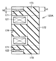
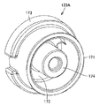
図3および図4を参照して、フェライトコア123Aは、筒状部171と、筒状部171の一方端を塞ぐ底部172と、筒状部の外表面に設けられる鍔部173と、底部172の表面に接続される中軸部174とを含む。なお、図3および図4に示すように、筒状部171、底部172、鍔部173、および中軸部174は、一体的に形成される。
Referring to FIGS. 3 and 4,
図3に示すように、検出コイル121は中軸部174に通された状態で筒状部171の内部に収納される。後述するように、検出コイル121は自己の形状を保つように固められた状態で筒状部171の内部に収納される。補助コイル122は、筒状部171の外表面において、筒状部171の開口端(すなわち筒状部171の2つの端部のうち、底部172に接続された端部と反対側に位置する端部)から鍔部173までの部分に直接的に巻回される。
As shown in FIG. 3, the
筒状部171の外表面を基準とした鍔部173の高さh1は、筒状部171の外表面を基準とした補助コイル122の高さh2よりも高くなるように設計されている。また、筒状部171の外表面に対して垂直な方向から見た状態では、補助コイル122の少なくとも一部が検出コイル121と重なり合う。
The height h1 of the
図5は、コイル組立体の製作工程を示す図である。図5を参照して、まずステップS1では、検出コイル121の巻き線処理が行なわれる。検出コイル121に用いられる導線はたとえば自己融着線である。また巻き線方法としては、たとえば積層巻が用いられる。自己融着線を巻き終えた後に加熱することによって、自己融着線の融着層同士が固着する。これにより検出コイル121は自己の形状を保つように固められ、かつ空芯コイルとなる。
FIG. 5 is a diagram showing a manufacturing process of the coil assembly. Referring to FIG. 5, first, in step S <b> 1, the winding process of
一方、ステップS2では、補助コイル122が作製される。ステップS2では自己融着線をフェライトコア123Aに巻き線する。さらに自己融着線を加熱することによって融着層を固着させる。
On the other hand, in step S2, the
なお、検出コイル121および補助コイル122の形状を固定する方法としては他の方法を用いることもできる。たとえばエナメルや樹脂系の接着剤等を用いて巻線の形状を固定してもよい。すなわち、検出コイル121および補助コイル122を形成するための導線は自己融着線に限定されるものではない。
It should be noted that other methods can be used as methods for fixing the shapes of the
ステップS2に続くステップS3では、補助コイル122の特性検査が実行される。
ステップS1およびステップS3の処理が終了するとステップS4の処理が実行される。ステップS4では、検出コイル121を筒状部171の内部に収納し、かつ、樹脂系の接着材により検出コイル121を固定する。
In step S3 following step S2, a characteristic inspection of the
When the processes of step S1 and step S3 are completed, the process of step S4 is executed. In step S4, the
続いてステップS5では検出コイル121の特性検査が実行される。ステップS5の処理が終了するとコイル組立体の製作処理が終了する。なお図5に示すように製作処理の順番が限定される必要はなく、処理の順番を適切に変更することも可能である。
Subsequently, in step S5, the characteristic inspection of the
本実施の形態の近接センサは「シールドタイプ」の近接センサとして好適に用いることができる。その理由として、近接センサは一般的に「シールドタイプ」および「非シールドタイプ」のいずれかに分類されるが、補助コイルは「シールドタイプ」の近接センサに搭載されるためである。この点に関し、まず、「シールドタイプ」の近接センサおよび「非シールドタイプ」の近接センサについて説明する。 The proximity sensor of this embodiment can be suitably used as a “shield type” proximity sensor. This is because proximity sensors are generally classified into either “shield type” or “non-shield type”, but the auxiliary coil is mounted on a “shield type” proximity sensor. In this regard, first, a “shield type” proximity sensor and a “non-shield type” proximity sensor will be described.
図6は、シールドタイプの近接センサおよび非シールドタイプの近接センサを示す図である。図6(A)はシールドタイプの近接センサを説明する図であり、図6(B)は非シールドタイプの近接センサを説明する図である。なお図6(A)に示す近接センサには補助コイルは含まれていない。この理由については後述する。 FIG. 6 is a diagram illustrating a shield type proximity sensor and a non-shield type proximity sensor. 6A is a diagram illustrating a shield type proximity sensor, and FIG. 6B is a diagram illustrating a non-shield type proximity sensor. Note that the proximity sensor shown in FIG. 6A does not include an auxiliary coil. The reason for this will be described later.
図6(A)に示すように、シールドタイプの近接センサの場合、金属ケース111の先端が検出面A(コイルケース124の表面)の近傍に位置するように金属ケース111が形成される。これにより、近接センサをその周囲の金属(周囲金属190)に取り付ける際に検出面Aと、周囲金属190の表面との間に段差を生じなくすることができる。すなわちシールドタイプの近接センサは周囲金属190への埋込設置が可能である。
As shown in FIG. 6A, in the case of a shield-type proximity sensor, the
コイルケース124の中には、フェライトコア123(たとえばポット形状のコア)および検出コイル121が設けられる。検出コイル121およびフェライトコア123を回路要素とする検出回路が高周波発振回路であるとする。その理由は補助コイルがなくとも、ある程度の磁気シールド効果を得ることが可能なためである。
In the
検出コイル121には、連続的に変化する励磁電流(たとえば波形が正弦波である励磁電流)が流れる。なお励磁電流の周波数は、たとえば数百kHz程度に定められる。
A continuously changing excitation current (for example, an excitation current having a sine wave waveform) flows through the
検出コイル121により生じた磁束Fが金属ケース111に浸透する深さ(すなわち表皮深さ)は励磁電流の周波数が大きいほど小さくなるが、磁束Fは金属ケース111を通過しない。さらに検出コイル121により生じた磁束Fが金属ケース111に浸透することによって金属ケース111に渦電流が流れる。この渦電流により生じた磁束の向きは検出コイル121により生じた磁束Fを打ち消す向きである。この結果、検出コイル121からの磁束分布の形状は、開磁路の先端すなわち検出面A上に磁束Fが集中するように変形する。すなわち、近接センサの側方(周囲金属190の表面に平行な方向)では検出コイル121により生じた磁束Fが周囲金属190によって遮蔽される効果(磁気シールド効果)が得られる。
The depth at which the magnetic flux F generated by the
一方、図6(B)に示すように、非シールドタイプの近接センサの場合、検出面Aは金属ケース111の先端よりも前方に位置するので周囲金属への埋込設置を行なうことはできない。非シールドタイプの近接センサの場合には、フェライトコア123にたとえばT型コアが用いられ、かつ検出面Aを金属ケース111の先端よりも前方に突出させる。この結果、検出面Aの前方に磁束Fを大きく広がることができるので検出対象と検出面Aとの距離を長くしても検出対象の有無あるいは位置を検出できる。なお非シールドタイプにおいては、近接センサの側方における磁束は遮蔽されていない。
On the other hand, as shown in FIG. 6B, in the case of a non-shielded proximity sensor, the detection surface A is located in front of the tip of the
シールドタイプの近接センサの場合、検出面Aの前方に磁束Fを集中させるため、センサ側方への検出コイルの磁束の広がりを抑制することが求められる。ここで、パルス電流を検出コイルに印加することにより検出コイルを励磁する方式の場合、その電流の周波数はたとえば数kHz程度に設定される。この場合、検出コイル121の磁束が金属ケース111を通過することによって、磁気シールド効果が十分に得られなくなることが起こり得る。しかし、補助コイルを設けることによってこの問題を回避することができる。
In the case of a shield type proximity sensor, in order to concentrate the magnetic flux F in front of the detection surface A, it is required to suppress the spread of the magnetic flux of the detection coil to the side of the sensor. Here, in the case of a system in which the detection coil is excited by applying a pulse current to the detection coil, the frequency of the current is set to about several kHz, for example. In this case, when the magnetic flux of the
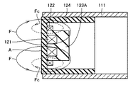
図7は、検出コイルからの磁束の向き、および補助コイルからの磁束の向きを説明する図である。図7を参照して、補助コイル122は検出コイル121の外側に配置される。つまり補助コイル122の径は検出コイル121の径よりも大きい。検出コイル121と補助コイル122とは直列に接続される。なお検出コイル121と補助コイル122とでは巻き方向が逆である。
FIG. 7 is a diagram illustrating the direction of magnetic flux from the detection coil and the direction of magnetic flux from the auxiliary coil. Referring to FIG. 7,
検出コイル121および補助コイル122に励磁電流が流れると、検出コイル121,補助コイル122によって磁束F,Fcがそれぞれ発生する。検出コイル121と補助コイル122とでは巻き方向が逆であるため、磁束Fcの向きと磁束Fの向きとは互いに逆向きである。すなわち磁束Fcの向きは磁束Fを打ち消す向きである。これにより近接センサの側方への磁束Fの広がりを抑制できるので、磁気シールド効果を得ることができる。つまり磁束Fを検出面Aの前方に集中させることが可能になるので検出感度を高めることができる。
When an excitation current flows through the
このように励磁電流の周波数を低い場合には磁気シールド効果を得るために補助コイルが設けられる。ただし連続的に変化する電流を検出コイルに印加する場合であっても、その電流の周波数によっては補助コイルが必要になることも起こり得る。したがって、連続的に変化する電流を検出コイルに印加する場合にも磁気シールド効果を得るために補助コイルが用いられてもよい。 Thus, when the frequency of the excitation current is low, an auxiliary coil is provided to obtain a magnetic shield effect. However, even when a continuously changing current is applied to the detection coil, an auxiliary coil may be required depending on the frequency of the current. Therefore, an auxiliary coil may be used to obtain a magnetic shielding effect even when a continuously changing current is applied to the detection coil.
補助コイル122は薄肉コイルであるため、検出コイル121と同じように、予め空芯コイルとして作製することは容易ではない。よって、補助コイルを作製するためには、導線を何らかの部材に巻きつけることが必要である。本実施の形態では、フェライトコア123Aの外表面に補助コイル122を直接的に巻きつける。これによって、補助コイル122を巻き付けるための部材(ボビン)が不要になる。
Since the
ボビンが不要になることにより、次のような効果が得られる。まず、ボビンが不要であるので、コストを低減することができる。 By eliminating the need for the bobbin, the following effects can be obtained. First, since the bobbin is unnecessary, the cost can be reduced.
さらに、フェライトコア123Aの径を大きくできるので、検出コイル121の径も大きくすることができる。これによって、検出感度を向上させることができる。
Furthermore, since the diameter of the
さらに、補助コイル122の高さが鍔部の高さより小さいため、補助コイル122からフェライトコア123Aの外側に漏洩する磁束の幅が小さくなる。すなわち、センサ側方に漏洩する補助コイル122の磁束の幅を小さくすることができる。このことは、センサ側方への補助コイル122の磁束の広がりが抑制されていることを意味する。これによって、検出コイル121の磁束もセンサ側方に広がることが抑制されている。すなわち、優れた磁気シールド効果が得られる。よって近接センサの検出感度を向上させることができる。さらに、補助コイル122の外側に高透磁率の部材を設けなくても磁気シールド効果を得ることが可能になるので、近接センサのコストを低減できる。
Furthermore, since the height of the
また、鍔部173を筒状部171の外表面に設けることによって、コイル組立体を組立てた場合に、検出コイル121と補助コイル122との相対位置の精度を安定させることができる。これによって、検出コイル121の磁束の広がりと補助コイル122の磁束の広がりとが個体間で大きく異なることを回避することができるので、近接センサの検出性能の個体間のばらつきを小さくすることができる。
Further, by providing the
[実施の形態2]
実施の形態2に係る近接センサの全体構成は実施の形態1とほぼ同様であるがフェライトコアの構造が実施の形態1と異なる。したがって以下では実施の形態2に係る近接センサのうちのフェライトコアを主に説明する。なお実施の形態2に係る近接センサの他の部分については実施の形態1に係る近接センサの対応する部分と同様であるので以後の説明を繰返さない。
[Embodiment 2]
The overall configuration of the proximity sensor according to the second embodiment is substantially the same as that of the first embodiment, but the structure of the ferrite core is different from that of the first embodiment. Therefore, the ferrite core of the proximity sensor according to the second embodiment will be mainly described below. Since other parts of the proximity sensor according to the second embodiment are the same as the corresponding parts of the proximity sensor according to the first embodiment, the following description will not be repeated.
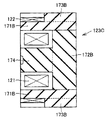
図8は、実施の形態2に係る近接センサに含まれるコイル組立体の構造を説明するための断面模式図である。図8を参照して、フェライトコア123Bは、筒状部171Aと、筒状部171Aの一方端を塞ぐ底部172Aと、筒状部171Aの外表面に設けられる鍔部173Aと、底部172Aの表面に接続される中軸部174とを含む。検出コイル121は中軸部174に通された状態で筒状部171Aの内部に収納される。補助コイル122は、筒状部171の外表面において、筒状部171Aの開口端から鍔部173Aまでの部分に直接的に巻回される。
FIG. 8 is a schematic cross-sectional view for explaining the structure of the coil assembly included in the proximity sensor according to the second embodiment. Referring to FIG. 8, ferrite core 123B includes a
筒状部171Aおよび鍔部173Aは一体的に形成され、かつフェライトコア123Bを構成する部品である。また、底部172Aおよび中軸部174は筒状部171Aおよび鍔部173Aとは別の部品として、一体的に形成される。筒状部171A(および鍔部173A)はたとえば樹脂係の接着剤により、底部172Aと接触した状態で固定される。
The
底部172Aおよび中軸部174はいわばT型コアを構成する。図6に示したようにT型コアは、非シールドタイプの近接センサに用いられる。実施の形態2によれば、T型コアを非シールドタイプの近接センサだけでなく、フェライトコア123の一部としても用いることができる。実施の形態2によれば、非シールドタイプとシールドタイプとでT型コアを共用できるので、近接センサの製造コストを低減することが可能になる。
The
なお、フェライトコアが、筒状部および鍔部を一体的に形成した部品と、底部および中軸部とを一体的に形成した部品とを含むのであれば、筒状部、鍔部および底部の形状は図8に示すように限定されるものではない。たとえば以下に示すように構成されたフェライトコアを近接センサに用いてもよい。 If the ferrite core includes a part in which the cylindrical part and the flange part are integrally formed and a part in which the bottom part and the central shaft part are integrally formed, the shape of the cylindrical part, the flange part and the bottom part Is not limited as shown in FIG. For example, a ferrite core configured as shown below may be used for the proximity sensor.
(フェライトコアの変形例)
図9は、実施の形態2に係る近接センサが備えるフェライトコアの変形例を示す図である。図9を参照して、フェライトコア123Cは、筒状部171Bと、筒状部171Bの一方端を塞ぐ底部172Bと、筒状部171Bの外表面に設けられる鍔部173Bとを含む。筒状部171Bおよび鍔部173Bは一体的に形成される。同様に底部172Bおよび中軸部174は一体的に形成される。図9と図3とを対比すれば分かるように、筒状部171B、鍔部173Bおよび底部172Bは、図3に示す筒状部171、鍔部173、および底部172にそれぞれ対応する。
(Modification example of ferrite core)
FIG. 9 is a diagram illustrating a modification of the ferrite core included in the proximity sensor according to the second embodiment. Referring to FIG. 9, ferrite core 123C includes a cylindrical portion 171B, a
[実施の形態3]
実施の形態3に係る近接センサの全体構成は実施の形態1とほぼ同様であるが、フェライトコアに収納される検出コイルの構成が実施の形態1と異なる。したがって以下では実施の形態3に係る近接センサのうち検出コイルを主に説明する。なお、実施の形態3に係る近接センサの他の部分については実施の形態1に係る近接センサの対応する部分と同様であるので以後の説明を繰返さない。
[Embodiment 3]
The overall configuration of the proximity sensor according to the third embodiment is substantially the same as that of the first embodiment, but the configuration of the detection coil housed in the ferrite core is different from that of the first embodiment. Therefore, the detection coil will be mainly described below in the proximity sensor according to the third embodiment. Since other parts of the proximity sensor according to the third embodiment are the same as the corresponding parts of the proximity sensor according to the first embodiment, the following description will not be repeated.
図10は、実施の形態3に係る近接センサに含まれるコイル組立体の構造を説明するための断面模式図である。図10を参照して、コイル組立体は、検出コイル121が巻回されたスプール175をさらに備える点で図3に示すコイル組立体と異なる。ただし、図10に示すコイル組立体の他の部分の構成は図3に示すコイル組立体の対応する部分の構成と同様である。スプール175の中心には貫通孔が形成される。この貫通孔に中軸部174が通されることにより検出コイル121は筒状部171の内部に収納される。
FIG. 10 is a schematic cross-sectional view for explaining the structure of the coil assembly included in the proximity sensor according to the third embodiment. Referring to FIG. 10, the coil assembly is different from the coil assembly shown in FIG. 3 in that it further includes a
スプール175は、2つのピン端子176を備える。2つのピン端子176の各々は底部172に形成された穴に通される。検出コイル121からの引出線は、ピン端子176に巻き付けられるとともに電気的に接続される。
The
なお、実施の形態3においては、フェライトコア123Aに代えて、図8に示すフェライトコア123Bあるいは図9に示すフェライトコア123Cが用いられてもよい。
In the third embodiment, ferrite core 123B shown in FIG. 8 or ferrite core 123C shown in FIG. 9 may be used instead of
一般的に検出コイルには線径の細い導線が用いられている。検出コイルの両端を回路基板に半田接続する際に、引出線を回路基板に直接的に接続した場合には断線が生じやすくなったり、接続作業に手間を要したりすることが考えられる。しかしながら、実施の形態3ではピン端子176を回路基板に半田接続することが可能になるのでこのような問題を回避することが可能になる。
Generally, a conductive wire having a thin wire diameter is used for the detection coil. When soldering both ends of the detection coil to the circuit board, if the lead wire is directly connected to the circuit board, disconnection is likely to occur, and it may be necessary to perform connection work. However, since the
今回開示された実施の形態はすべての点で例示であって制限的なものではないと考えられるべきである。本発明の範囲は、上記した実施の形態の説明ではなくて特許請求の範囲によって示され、特許請求の範囲と均等の意味および範囲内でのすべての変更が含まれることが意図される。 The embodiment disclosed this time should be considered as illustrative in all points and not restrictive. The scope of the present invention is shown not by the above description of the embodiments but by the scope of claims for patent, and is intended to include meanings equivalent to the scope of claims for patent and all modifications within the scope.
100 近接センサ、110 ケース体、111 金属ケース、112 樹脂ケース、113 開口部、120 検出部組立体、121 検出コイル、122 補助コイル、123,123A,123B,123C フェライトコア、124 コイルケース、125 検出回路基板、126 一次注型樹脂層、130 出力部組立体、131 出力回路基板、140 接続部材、150 外部接続用コード、160 コードプロテクタ、171,171A,171B 筒状部、172,172A,172B 底部、173,173A,173B 鍔部、174 中軸部、175 スプール、176 ピン端子、180 二次注型樹脂層、190 周囲金属、A 検出面、F,Fc 磁束。 100 proximity sensor, 110 case body, 111 metal case, 112 resin case, 113 opening, 120 detector assembly, 121 detection coil, 122 auxiliary coil, 123, 123A, 123B, 123C ferrite core, 124 coil case, 125 detection Circuit board, 126 Primary casting resin layer, 130 Output assembly, 131 Output circuit board, 140 Connection member, 150 External connection cord, 160 Code protector, 171, 171A, 171B Cylindrical part, 172, 172A, 172B Bottom , 173, 173A, 173B collar part, 174 middle shaft part, 175 spool, 176 pin terminal, 180 secondary cast resin layer, 190 surrounding metal, A detection surface, F, Fc magnetic flux.
Claims (7)
前記磁界を発生させるための検出コイルと、
筒状部と、前記筒状部の一方端を塞ぐ底部と、前記筒状部の外表面に設けられる鍔部とを含み、かつ、前記筒状部の中に前記検出コイルを収納するコアと、
前記筒状部の前記外表面における前記筒状部の他方端から前記鍔部までの部分に直接的に巻回され、かつ、前記検出コイルから発生される磁界の方向を調整する磁界を発生させる補助コイルとを備える、近接センサ。 A proximity sensor that detects the presence or position of a metal body using a magnetic field,
A detection coil for generating the magnetic field;
A core that includes a tubular portion, a bottom portion that closes one end of the tubular portion, and a flange provided on an outer surface of the tubular portion, and that houses the detection coil in the tubular portion; ,
A magnetic field that is directly wound around a portion of the outer surface of the cylindrical portion from the other end of the cylindrical portion to the flange and adjusts the direction of the magnetic field generated from the detection coil is generated. A proximity sensor comprising an auxiliary coil.
前記コアは、前記底部に接続され、かつ検出コイルが通される中軸部をさらに含む、請求項1または2のいずれか1項に記載の近接センサ。 The detection coil is housed inside the cylindrical portion in a state of being hardened so as to maintain its own shape,
The proximity sensor according to claim 1, wherein the core further includes a middle shaft portion that is connected to the bottom portion and through which a detection coil is passed.
前記筒状部と前記鍔部とを一体化した部品と、
前記底部と前記中軸部とを一体化した部品とを含む、請求項3に記載の近接センサ。 The core is
A component in which the tubular portion and the flange portion are integrated;
The proximity sensor according to claim 3, comprising a part in which the bottom part and the middle shaft part are integrated.
前記検出コイルが巻回されたスプールをさらに備え、
前記検出コイルは、前記スプールとともに前記筒状部内部に収納される、請求項1から5のいずれか1項に記載の近接センサ。 The proximity sensor is
A spool around which the detection coil is wound;
The proximity sensor according to claim 1, wherein the detection coil is housed in the cylindrical portion together with the spool.
Priority Applications (1)
| Application Number | Priority Date | Filing Date | Title |
|---|---|---|---|
| JP2007206308A JP5115084B2 (en) | 2007-08-08 | 2007-08-08 | Proximity sensor |
Applications Claiming Priority (1)
| Application Number | Priority Date | Filing Date | Title |
|---|---|---|---|
| JP2007206308A JP5115084B2 (en) | 2007-08-08 | 2007-08-08 | Proximity sensor |
Publications (2)
| Publication Number | Publication Date |
|---|---|
| JP2009043512A JP2009043512A (en) | 2009-02-26 |
| JP5115084B2 true JP5115084B2 (en) | 2013-01-09 |
Family
ID=40444054
Family Applications (1)
| Application Number | Title | Priority Date | Filing Date |
|---|---|---|---|
| JP2007206308A Active JP5115084B2 (en) | 2007-08-08 | 2007-08-08 | Proximity sensor |
Country Status (1)
| Country | Link |
|---|---|
| JP (1) | JP5115084B2 (en) |
Families Citing this family (1)
| Publication number | Priority date | Publication date | Assignee | Title |
|---|---|---|---|---|
| JP6900771B2 (en) * | 2017-05-09 | 2021-07-07 | オムロン株式会社 | Proximity sensor and method |
Family Cites Families (7)
| Publication number | Priority date | Publication date | Assignee | Title |
|---|---|---|---|---|
| JP2603628B2 (en) * | 1987-01-28 | 1997-04-23 | オムロン株式会社 | High frequency oscillation type proximity switch |
| JPH05144355A (en) * | 1991-11-26 | 1993-06-11 | Fuji Electric Co Ltd | Proximity switch |
| EP0936738A1 (en) * | 1998-02-13 | 1999-08-18 | Optosys SA | Inductive proximity switch with one-piece housing |
| JP2000164090A (en) * | 1998-11-30 | 2000-06-16 | Omron Corp | Sensor head and proximity sensor using the same |
| JP2001006939A (en) * | 1999-06-22 | 2001-01-12 | Mitsumi Electric Co Ltd | Coil apparatus |
| JP3716696B2 (en) * | 1999-11-25 | 2005-11-16 | 東洋電装株式会社 | Trance |
| US7394243B2 (en) * | 2001-03-15 | 2008-07-01 | Omron Corporation | Proximity sensor |
-
2007
- 2007-08-08 JP JP2007206308A patent/JP5115084B2/en active Active
Also Published As
| Publication number | Publication date |
|---|---|
| JP2009043512A (en) | 2009-02-26 |
Similar Documents
| Publication | Publication Date | Title |
|---|---|---|
| JP5034776B2 (en) | Proximity sensor | |
| JP4796060B2 (en) | Current sensor | |
| JP5167305B2 (en) | Current detector | |
| US9400292B2 (en) | Electrical current sensor with grounded magnetic core | |
| CN106716836B (en) | Sensor element of an inductive proximity sensor or distance sensor and method for operating the sensor element | |
| EP1416635B1 (en) | Sensor device | |
| JP2007096652A (en) | Speaker | |
| US6121770A (en) | Magnetic sensor using magnetic impedance of magnetic wire within biasing coil | |
| JP2923854B2 (en) | Magnetic induction flow meter | |
| US20100259282A1 (en) | Detector for proximity sensor and proximity sensor | |
| JP4978377B2 (en) | Proximity sensor | |
| JP5115084B2 (en) | Proximity sensor | |
| US7106052B2 (en) | Inductive proximity switch with differential coil arrangement | |
| JP6203141B2 (en) | Switch device and non-contact switch | |
| JP6605007B2 (en) | Current detector | |
| JP2008091147A (en) | Proximity sensor and core for the sensor | |
| JP6868894B2 (en) | Current detector and electronic component mount | |
| JP2009042152A (en) | Magnetic detection probe and method of manufacturing the magnetic detection probe | |
| JP2009264992A (en) | Induction type proximity sensor | |
| JP2003127830A (en) | Seat belt setting/removal sensor | |
| JP2005221342A (en) | Coil-type current sensor | |
| JP2004077135A (en) | Displacement sensor | |
| JP2005285844A (en) | Transformer for detecting quantity of electricity | |
| JP2000321011A (en) | Magnetic detector, thickness detector and level detector of magnetic body | |
| EP1862824A1 (en) | Temperature compensated circuit and inductive sensor comprising said circuit |
Legal Events
| Date | Code | Title | Description |
|---|---|---|---|
| A621 | Written request for application examination |
Free format text: JAPANESE INTERMEDIATE CODE: A621 Effective date: 20100607 |
|
| A977 | Report on retrieval |
Free format text: JAPANESE INTERMEDIATE CODE: A971007 Effective date: 20120314 |
|
| A131 | Notification of reasons for refusal |
Free format text: JAPANESE INTERMEDIATE CODE: A131 Effective date: 20120321 |
|
| TRDD | Decision of grant or rejection written | ||
| A01 | Written decision to grant a patent or to grant a registration (utility model) |
Free format text: JAPANESE INTERMEDIATE CODE: A01 Effective date: 20120918 |
|
| A01 | Written decision to grant a patent or to grant a registration (utility model) |
Free format text: JAPANESE INTERMEDIATE CODE: A01 |
|
| A61 | First payment of annual fees (during grant procedure) |
Free format text: JAPANESE INTERMEDIATE CODE: A61 Effective date: 20121001 |
|
| R150 | Certificate of patent or registration of utility model |
Free format text: JAPANESE INTERMEDIATE CODE: R150 Ref document number: 5115084 Country of ref document: JP Free format text: JAPANESE INTERMEDIATE CODE: R150 |
|
| FPAY | Renewal fee payment (event date is renewal date of database) |
Free format text: PAYMENT UNTIL: 20151026 Year of fee payment: 3 |