JP5114745B2 - Steel material conveyance control apparatus and method in hot rolling equipment - Google Patents
Steel material conveyance control apparatus and method in hot rolling equipment Download PDFInfo
- Publication number
- JP5114745B2 JP5114745B2 JP2008096097A JP2008096097A JP5114745B2 JP 5114745 B2 JP5114745 B2 JP 5114745B2 JP 2008096097 A JP2008096097 A JP 2008096097A JP 2008096097 A JP2008096097 A JP 2008096097A JP 5114745 B2 JP5114745 B2 JP 5114745B2
- Authority
- JP
- Japan
- Prior art keywords
- steel material
- rough rolling
- speed
- heating device
- deceleration
- Prior art date
- Legal status (The legal status is an assumption and is not a legal conclusion. Google has not performed a legal analysis and makes no representation as to the accuracy of the status listed.)
- Active
Links
Images


Description
本発明は、粗圧延機、加熱装置、剪断機、及び仕上圧延機を順に配置した熱間圧延設備における鋼材の搬送制御装置及び方法に関する。 The present invention relates to a steel material conveyance control device and method in a hot rolling facility in which a rough rolling mill, a heating device, a shearing device, and a finishing rolling mill are sequentially arranged.
連続熱間圧延設備では、粗圧延機でスラブを中間板厚まで圧延し、粗圧延後の鋼材(粗バー)を搬送して、該粗バーの先端部及び後端部のクロップ(形状不良部)を剪断機(クロップシャー)で剪断した後、仕上圧延機で製品板厚まで圧延する。仕上圧延機を出たストリップは、冷却後、巻取機で巻き取られてコイル製品となる。 In continuous hot rolling equipment, the slab is rolled to an intermediate plate thickness with a roughing mill, the steel material (rough bar) after rough rolling is transported, and the front end and rear end crops of the rough bar (shape defect part). ) Is sheared by a shearing machine (crop shear) and then rolled to a product plate thickness by a finishing mill. The strip that has exited the finish rolling mill is cooled and wound by a winder to form a coil product.
近年の連続熱間圧延設備では、加熱炉操業の高効率化から燃料原単位の削減が図られ、スラブ加熱温度の低下や均熱不足によって生じる粗バーの低温部を加熱して温度上昇させるために、搬送ライン上に誘導加熱装置を配置している(例えば特許文献1、2を参照)。 In recent continuous hot rolling facilities, the efficiency of heating furnace operation has been reduced to reduce the fuel consumption rate, and the temperature of the low temperature part of the coarse bar caused by the decrease in slab heating temperature or insufficient soaking is heated to raise the temperature. In addition, an induction heating device is disposed on the transport line (see, for example, Patent Documents 1 and 2).
誘導加熱装置による温度上昇代は、粗バーが該誘導加熱装置を通過する速度に逆比例するため、経済的効果が得られるよう温度上昇代を確保するためには、粗バーの速度を大幅に減速する必要がある。 The temperature increase due to the induction heating device is inversely proportional to the speed at which the coarse bar passes through the induction heating device. Therefore, in order to secure the temperature increase allowance for obtaining an economic effect, the speed of the coarse bar is greatly increased. Need to slow down.
そして、粗バーでは、特に先端部での温度低下が大きいため、先端部を加熱して温度上昇させることが要求される。 In the coarse bar, the temperature drop at the tip is particularly large, and it is required to heat the tip to raise the temperature.
本発明は上記のような点に鑑みてなされたものであり、全体の搬送効率をできるだけ低下させないで、粗圧延後の粗バーの先端部を加熱できるようにすることを目的とする。 The present invention has been made in view of the above points, and an object of the present invention is to enable heating of the end portion of the rough bar after rough rolling without reducing the overall conveyance efficiency as much as possible.
本発明の熱間圧延設備における鋼材の搬送制御装置は、粗圧延機、加熱装置、粗圧延後の鋼材のクロップを剪断する剪断機、及び仕上圧延機を順に配置した熱間圧延設備において鋼材の搬送を制御する鋼材の搬送制御装置であって、
前記粗圧延後の鋼材の搬送速度を前記剪断機に通板させるために減速させる際に、減速完了時における前記粗圧延後の鋼材の先端位置が、予め設定した前記加熱装置の入側位置又はそれよりも上流位置となるように、前記粗圧延機と前記加熱装置との間にある前記粗圧延後の鋼材の搬送速度と、予め設定した前記剪断機に通板させるための速度と、予め設定した前記粗圧延後の鋼材の搬送速度から前記剪断機に通板させるための速度に減速するための減速率とに基づいて、前記粗圧延後の鋼材の減速開始位置を演算する演算手段と、
前記粗圧延後の鋼材の先端位置が前記減速開始位置に到達すると、前記減速率で減速を開始する制御手段とを備え、
前記加熱装置の入側位置又はそれよりも上流位置とは、前記加熱装置の入側位置又はそれよりも2[m]以下の上流位置であることを特徴とする。
本発明の熱間圧延設備における鋼材の搬送制御方法は、粗圧延機、加熱装置、粗圧延後の鋼材のクロップを剪断する剪断機、及び仕上圧延機を順に配置した熱間圧延設備において鋼材の搬送を制御鋼材の搬送制御方法であって、
前記粗圧延後の鋼材の搬送速度を前記剪断機に通板させるために減速させる際に、減速完了時における前記粗圧延後の鋼材の先端位置が、予め設定した前記加熱装置の入側位置又はそれよりも上流位置となるように、前記粗圧延機と前記加熱装置との間にある前記粗圧延後の鋼材の搬送速度と、予め設定した前記剪断機に通板させるための速度と、予め設定した前記粗圧延後の鋼材の搬送速度から前記剪断機に通板させるための速度に減速するための減速率とに基づいて、前記粗圧延後の鋼材の減速開始位置を演算する演算手順と、
前記粗圧延後の鋼材の先端位置が前記減速開始位置に到達すると、前記減速率で減速を開始する制御手順とを有し、
前記加熱装置の入側位置又はそれよりも上流位置とは、前記加熱装置の入側位置又はそれよりも2[m]以下の上流位置であることを特徴とする。
The steel material conveyance control device in the hot rolling facility of the present invention includes a rough rolling machine, a heating device, a shearing machine that shears a crop of steel material after rough rolling, and a hot rolling facility in which a finishing rolling mill is arranged in order. A steel material conveyance control device for controlling conveyance,
When decelerating the conveying speed of the steel material after the rough rolling so as to pass through the shearing machine, the front end position of the steel material after the rough rolling at the time of completion of the deceleration is a preset entry side position of the heating device or In order to be in an upstream position than that, the conveyance speed of the steel material after the rough rolling between the rough rolling mill and the heating device, the speed for passing through the preset shearing machine, A calculation means for calculating a deceleration start position of the steel material after the rough rolling based on the set reduction rate for reducing the speed from the conveyance speed of the steel material after the rough rolling to the speed for passing through the shearing machine. ,
When the tip position of the steel material after the rough rolling reaches the deceleration start position, a control means for starting deceleration at the deceleration rate,
The entrance position of the heating device or the upstream position thereof is an entrance position of the heating device or an upstream position of 2 [m] or less from the entrance position .
The steel material conveyance control method in the hot rolling facility of the present invention includes a rough rolling machine, a heating device, a shearing machine for shearing a crop of steel material after rough rolling, and a hot rolling facility in which a finishing rolling mill is disposed in order. A method for controlling the conveyance of steel,
When decelerating the conveying speed of the steel material after the rough rolling so as to pass through the shearing machine, the front end position of the steel material after the rough rolling at the time of completion of the deceleration is a preset entry side position of the heating device or In order to be in an upstream position than that, the conveyance speed of the steel material after the rough rolling between the rough rolling mill and the heating device, the speed for passing through the preset shearing machine, A calculation procedure for calculating a deceleration start position of the steel material after the rough rolling based on the set reduction rate for reducing the speed from the conveyance speed of the steel material after the rough rolling to the speed for passing through the shearing machine, and ,
When the tip position of the steel material after the rough rolling reaches the deceleration start position, a control procedure for starting deceleration at the deceleration rate,
The entrance position of the heating device or the upstream position thereof is an entrance position of the heating device or an upstream position of 2 [m] or less from the entrance position .
本発明によれば、粗圧延後の鋼材の搬送速度を剪断機に通板させるために減速させる際に、減速完了時における該粗圧延後の鋼材の先端位置が、加熱装置の入側位置又はそれよりも上流位置となるように制御するので、全体の搬送効率をできるだけ低下させないで、粗圧延後の粗バーの先端部を加熱することができる。 According to the present invention, when slowing down the conveying speed of the steel material after the rough rolling so as to pass through the shearing machine, the tip position of the steel material after the rough rolling at the time of completion of the deceleration is the entry side position of the heating device or Since it controls so that it may become an upstream position rather than that, the front-end | tip part of the rough bar after rough rolling can be heated, without reducing the whole conveyance efficiency as much as possible.
以下、添付図面を参照して、本発明の好適な実施形態について説明する。
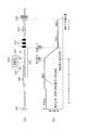
図1(a)に、本発明の実施形態に係る連続熱間圧延設備の概略構成を示す。連続熱間圧延設備では、搬送ライン上に、粗圧延機101、誘導加熱装置103、剪断機104、及び仕上圧延機105が順に配置されている。
Preferred embodiments of the present invention will be described below with reference to the accompanying drawings.
FIG. 1A shows a schematic configuration of a continuous hot rolling facility according to an embodiment of the present invention. In the continuous hot rolling facility, a
粗圧延機101でスラブを中間板厚まで圧延し、粗圧延後の鋼材(粗バー)100を搬送ローラテーブル102により1本ずつ搬送して、仕上圧延機105で製品板厚まで圧延する。この場合に、誘導加熱装置103では、粗バー100の低温部を加熱して温度上昇させる。また、ドラム型クロップシャー等からなる剪断機104では、粗バー100の先端部及び後端部のクロップを剪断する。
The slab is rolled to an intermediate plate thickness by the
搬送ラインの上方には、粗バー100の搬送速度を測定する速度測定器107(例えばメジャーリングロール)が配設されている。
Above the transport line, a speed measuring device 107 (for example, a measuring roll) that measures the transport speed of the
本実施形態に係る連続熱間圧延設備では、搬送制御装置200が、搬送ローラテーブル102の駆動部に指示する等して鋼材の搬送を制御する。搬送制御装置200は、詳しくは後述するが、粗バー100の搬送速度を剪断機104に通板させるために減速させる際に、その減速開始位置を演算する演算部201を備える。
In the continuous hot rolling facility according to the present embodiment, the
図1(b)に、鋼材の先端位置と搬送速度との推移関係を示す。鋼材(スラブ)が粗圧延機101を通過する間(粗バー100の先端が粗圧延機101を抜けるまでの間)、すなわち図1(b)に示す範囲a(粗圧延機101の前後)では、鋼材を粗圧延機101に通板させるための搬送速度で搬送する。図1(b)では、範囲aでの搬送速度を4.5[m/s]としている。なお、粗圧延機101で圧延した鋼材、すなわち粗バー100は、長さが50〜100[m]程度のものが主体となる。
FIG. 1B shows a transition relationship between the tip position of the steel material and the conveyance speed. While the steel material (slab) passes through the rough rolling mill 101 (until the tip of the
粗圧延機101を通過すると、図1(b)に示す範囲b(粗圧延機101と誘導加熱装置103との間であって、粗バー100が搬送されるだけの範囲)では、搬送効率を高めるために粗バー100を比較的高速で搬送する。図1(b)では、粗バー100を搬送ラインの最大能力の搬送速度(最高速度)である5[m/s]で搬送している。ここで、図1(b)では、常に粗バー100を最高速度で搬送している例を示しているが、実際には先行材との間隔を確保するために搬送速度を調整し、最高速度より落とすこともある。
When passing through the rough
その後、粗バー100の先端が剪断機104に到達する前に、粗バー100の搬送速度を剪断機104に通板させるための速度(剪断速度)まで減速させる必要がある。図1(b)では、搬送速度を1[m/s]まで減速させるようにしている。
Thereafter, before the tip of the
ここで、誘導加熱装置103による温度上昇代を確保するためには、粗バー100の通過速度を1〜2[m/s]程度まで減速させることが好ましい。また、粗バー100では、特に先端部での温度低下が大きいため、先端部を加熱して温度上昇させることが要求される。
Here, in order to secure the temperature increase allowance by the
そこで、搬送制御装置200は、粗バー100の搬送速度を剪断速度まで減速させる際に、減速完了時における粗バー100の先端位置が、誘導加熱装置103の入側位置又はそれよりも上流位置となるように制御する。かかる制御により、粗バー100の先端が誘導加熱装置103に到達する前に、粗バー100の搬送速度を剪断速度まで減速させることができ、誘導加熱装置103で粗バー100の先端部を加熱して温度上昇させることができる。
Therefore, when the
搬送効率からいえば、減速完了時における粗バー100の先端位置が、ちょうど誘導加熱装置103の入側位置(0[m]位置)となるのが理想である。実操業では、粗バー100の搬送ローラテーブル102上での滑りや制御の応答遅れ等を考慮して、減速完了時における粗バー100の先端位置が、誘導加熱装置103の入側位置よりも2[m]以下の上流位置となるよう制御する。
From the viewpoint of conveyance efficiency, it is ideal that the tip position of the
なお、粗バー100の先端が剪断機104を通過後、仕上圧延機105に到達するまでの間、すなわち図1(b)に示す範囲cでは、粗バー100を仕上圧延機105に通板させるための搬送速度で搬送する。図1(b)では、範囲cでの搬送速度を0.8[m/s]としている。
In addition, after the front-end | tip of the
次に、図2を参照して、減速完了時における粗バー100の先端位置が、誘導加熱装置103の入側位置又はそれよりも上流位置となるように制御する制御例を説明する。
Next, with reference to FIG. 2, a control example will be described in which control is performed so that the leading end position of the
図2(a)は、減速開始位置を予め定めている制御例を示す。搬送制御装置200は、所定の減速率で減速させる構成となっている。この場合、図1(b)に示す範囲bにおいて粗バー100を最高速度(5[m/s])で搬送しているものと想定すれば、減速完了時における粗バー100の先端位置が、予め設定した減速完了位置(誘導加熱装置103の0[m]位置〜上流側2[m]の位置)となるように、減速開始位置を定めることができる(図2(a)の特性線S1)。
FIG. 2A shows a control example in which the deceleration start position is determined in advance. The
そこで、上述したように予め設定した減速開始位置に粗バー100のセンサ、例えばスキャン型ホットメタルディテクタ(HMD)106を設置しておき、センサ106で粗バー100の先端を検知したときに減速を開始するようにしている。
Therefore, as described above, a sensor for the
ところが、上述したように、図1(b)に示す範囲bにおいて常に粗バー100を最高速度(5[m/s])で搬送しているとは限らず、先行材との関係等では搬送速度を最高速度(5[m/s])より落とすことがある。そして、粗バー100の搬送速度が低速の場合、図2(a)の特性線S2に示すように、センサ106で粗バー100の先端を検知したことを受けて前記所定の減速率で減速させると、誘導加熱装置103のかなり手前の位置で減速が完了することになり、搬送効率が悪くなってしまう。
However, as described above, the
そこで、本実施形態では、図2(b)に示すように、搬送制御装置200の演算部201により減速開始位置を演算し、予め設定した減速完了位置(誘導加熱装置103の0[m]位置〜上流側2[m]の位置)で減速が完了するようにしている。
Therefore, in the present embodiment, as shown in FIG. 2B, the deceleration start position is calculated by the
図3を参照して、搬送制御装置200の演算部201での演算処理を説明する。搬送制御装置200では、粗圧延機101と誘導加熱装置103との間(図1(b)に示す範囲b)にある粗バー100の現在の搬送速度V1を測定器107を介して検知する。なお、現在の搬送速度V1を測定器107で測定する例を説明したが、搬送制御装置200で現在設定している搬送速度を現在の搬送速度V1として検知するようにしてもよい。
With reference to FIG. 3, the calculation process in the
また、搬送制御装置200には、剪断速度V2(1[m/s])、減速完了位置A(誘導加熱装置103の0[m]位置〜上流側2[m]の位置)、所定の加減速率αが予め設定されている。なお、位置A、後述する位置B、Cは、例えば図1に示した範囲bの最上流位置を0とし、上流から下流を+方向とした値を考える。
Further, the
ステップS101で、演算部201は、現在の搬送速度V1に基づいて、下式(1)により粗バー100の先端位置Cを演算することにより、粗バー100の先端位置Cをトラッキングする。
C=∫V1・・・(1)
In step S101, the
C = ∫V 1 (1)
また、ステップS102で、現在の搬送速度V1と、剪断速度V2とに基づいて、下式(2)により減速距離Xを演算する。減速距離Xは、所定の加減速率αの下で現在の搬送速度V1から剪断速度V2まで減速させるのに要する距離である。
X=(V1 2−V2 2)/2α・・・(2)
Further, in step S102, the current conveying speed V 1, on the basis of the shear rate V 2, and calculates the deceleration distance X by the following equation (2). The deceleration distance X is a distance required to decelerate from the current conveying speed V 1 to the shearing speed V 2 under a predetermined acceleration / deceleration rate α.
X = (V 1 2 −V 2 2 ) / 2α (2)
次に、ステップS103で、下式(3)により減速開始位置Bを演算する。
B=A−X・・・(3)
Next, in step S103, the deceleration start position B is calculated by the following equation (3).
B = A−X (3)
そして、ステップS104で、粗バー100の先端位置Cが減速開始位置Bに到達しているかどうか(B≦Cとなったかどうか)を判定し、B≦Cとなれば、所定の加減速率αで減速を開始する。
In step S104, it is determined whether or not the tip position C of the
図2(b)には、図3で説明したように減速開始位置を演算する制御の場合の特性を示す。減速開始位置を可変とすることにより、図1(b)に示す範囲bにおいて粗バー100の搬送速度が最高速度(5[m/s])である場合(特性線S3)でも、搬送速度を最高速度(5[m/s])より落としている場合(特性線S4)でも、予め設定した減速完了位置で減速を完了させることができる。これにより、粗バー100の先端が誘導加熱装置103に到達する直前で、粗バー100の搬送速度を剪断速度まで減速させることができ、搬送効率を向上させることができる。
FIG. 2B shows characteristics in the case of the control for calculating the deceleration start position as described in FIG. By making the deceleration start position variable, even when the transport speed of the
また、図2(a)の制御例のようにセンサ106を必要とせず、コストダウンを図ることもできる。 Further, unlike the control example of FIG. 2A, the sensor 106 is not required, and the cost can be reduced.
以上、本発明を実施形態と共に説明したが、本発明は実施形態にのみ限定されるものではなく、本発明の範囲内で変更等が可能である。例えば上記実施形態では、減速率αを一定にして減速開始位置Bを可変とする例を説明したが、減速開始位置Bを一定にして減速率αを可変とするようにしてもよい。すなわち、減速完了時における粗バー100の先端位置が、予め設定した減速完了位置A(誘導加熱装置103の0[m]位置〜上流側2[m]の位置)となるように、粗バー100の現在の搬送速度V1と、予め設定した剪断速度V2と、予め設定した減速開始位置Bとに基づいて、上式(2)、(3)により減速率αを演算するようにしてもよい。この場合も、粗バー100の先端が誘導加熱装置103に到達する直前で、粗バー100の搬送速度を剪断速度まで減速させることができ、搬送効率を向上させることができる。
As mentioned above, although this invention was demonstrated with embodiment, this invention is not limited only to embodiment, A change etc. are possible within the scope of the present invention. For example, in the above embodiment, the example in which the deceleration rate α is constant and the deceleration start position B is variable has been described, but the deceleration start position B may be constant and the deceleration rate α may be variable. That is, the
ただし、全体の搬送効率からいえば、減速率αを搬送ラインの最大能力の加減速率(最高加減速率)に一定にしておき、減速開始位置Bを演算するのが望ましい。 However, in terms of the overall conveyance efficiency, it is desirable to calculate the deceleration start position B while keeping the deceleration rate α constant at the maximum acceleration / deceleration rate (maximum acceleration / deceleration rate) of the conveyance line.
なお、本発明を適用した鋼板の搬送制御装置は、具体的にはCPU、各種メモリを備えたコンピュータ装置により実現可能であり、一つの機器により構成されてもよいし、複数の機器により構成されてもよい。 The steel sheet conveyance control device to which the present invention is applied can be realized by a computer device having a CPU and various memories, and may be constituted by a single device or a plurality of devices. May be.
また、本発明の目的は、上述した実施形態の機能を実現するソフトウェアのプログラムコードを記録した記憶媒体を、システム或いは装置に供給することによっても達成される。この場合、そのシステム或いは装置のコンピュータ(又はCPUやMPU)が記憶媒体に格納されたプログラムコードを読み出し実行する。 The object of the present invention can also be achieved by supplying a storage medium storing software program codes for realizing the functions of the above-described embodiments to a system or apparatus. In this case, the computer (or CPU or MPU) of the system or apparatus reads and executes the program code stored in the storage medium.
この場合、記憶媒体から読み出されたプログラムコード自体が上述した実施形態の機能を実現することになり、プログラムコード自体及びそのプログラムコードを記憶した記憶媒体は本発明を構成することになる。プログラムコードを供給するための記憶媒体としては、例えば、フレキシブルディスク、ハードディスク、光ディスク、光磁気ディスク、CD−ROM、CD−R、磁気テープ、不揮発性のメモリカード、ROM等を用いることができる。 In this case, the program code itself read from the storage medium realizes the functions of the above-described embodiments, and the program code itself and the storage medium storing the program code constitute the present invention. As a storage medium for supplying the program code, for example, a flexible disk, a hard disk, an optical disk, a magneto-optical disk, a CD-ROM, a CD-R, a magnetic tape, a nonvolatile memory card, a ROM, or the like can be used.
100:粗バー
101:粗圧延機
102:搬送ローラテーブル
103:誘導加熱装置
104:剪断機
105:仕上圧延機
106:センサ
107:速度測定器
200:搬送制御装置
201:演算部
DESCRIPTION OF SYMBOLS 100: Rough bar 101: Rough rolling mill 102: Conveyance roller table 103: Induction heating apparatus 104: Shearing machine 105: Finishing mill 106: Sensor 107: Speed measuring device 200: Conveyance control apparatus 201: Arithmetic unit
Claims (2)
前記粗圧延後の鋼材の搬送速度を前記剪断機に通板させるために減速させる際に、減速完了時における前記粗圧延後の鋼材の先端位置が、予め設定した前記加熱装置の入側位置又はそれよりも上流位置となるように、前記粗圧延機と前記加熱装置との間にある前記粗圧延後の鋼材の搬送速度と、予め設定した前記剪断機に通板させるための速度と、予め設定した前記粗圧延後の鋼材の搬送速度から前記剪断機に通板させるための速度に減速するための減速率とに基づいて、前記粗圧延後の鋼材の減速開始位置を演算する演算手段と、
前記粗圧延後の鋼材の先端位置が前記減速開始位置に到達すると、前記減速率で減速を開始する制御手段とを備え、
前記加熱装置の入側位置又はそれよりも上流位置とは、前記加熱装置の入側位置又はそれよりも2[m]以下の上流位置であることを特徴とする熱間圧延設備における鋼材の搬送制御装置。 A steel material transport control device for controlling steel material transport in a hot rolling facility in which a rough rolling mill, a heating device, a shearing machine for shearing a crop of steel material after rough rolling, and a finish rolling mill are arranged in order,
When decelerating the conveying speed of the steel material after the rough rolling so as to pass through the shearing machine, the front end position of the steel material after the rough rolling at the time of completion of the deceleration is a preset entry side position of the heating device or In order to be in an upstream position than that, the conveyance speed of the steel material after the rough rolling between the rough rolling mill and the heating device, the speed for passing through the preset shearing machine, A calculation means for calculating a deceleration start position of the steel material after the rough rolling based on the set reduction rate for reducing the speed from the conveyance speed of the steel material after the rough rolling to the speed for passing through the shearing machine. ,
When the tip position of the steel material after the rough rolling reaches the deceleration start position, a control means for starting deceleration at the deceleration rate,
The entrance position of the heating device or the upstream position thereof is the entrance position of the heating device or an upstream position of 2 [m] or less from the entrance position of the heating device. Control device.
前記粗圧延後の鋼材の搬送速度を前記剪断機に通板させるために減速させる際に、減速完了時における前記粗圧延後の鋼材の先端位置が、予め設定した前記加熱装置の入側位置又はそれよりも上流位置となるように、前記粗圧延機と前記加熱装置との間にある前記粗圧延後の鋼材の搬送速度と、予め設定した前記剪断機に通板させるための速度と、予め設定した前記粗圧延後の鋼材の搬送速度から前記剪断機に通板させるための速度に減速するための減速率とに基づいて、前記粗圧延後の鋼材の減速開始位置を演算する演算手順と、
前記粗圧延後の鋼材の先端位置が前記減速開始位置に到達すると、前記減速率で減速を開始する制御手順とを有し、
前記加熱装置の入側位置又はそれよりも上流位置とは、前記加熱装置の入側位置又はそれよりも2[m]以下の上流位置であることを特徴とする熱間圧延設備における鋼材の搬送制御方法。 In a hot rolling facility in which a rough rolling mill, a heating device, a shearing machine that shears a crop of steel material after rough rolling, and a finishing rolling mill are sequentially arranged, the steel material is transported and controlled.
When decelerating the conveying speed of the steel material after the rough rolling so as to pass through the shearing machine, the front end position of the steel material after the rough rolling at the time of completion of the deceleration is a preset entry side position of the heating device or In order to be in an upstream position than that, the conveyance speed of the steel material after the rough rolling between the rough rolling mill and the heating device, the speed for passing through the preset shearing machine, A calculation procedure for calculating a deceleration start position of the steel material after the rough rolling based on the set reduction rate for reducing the speed from the conveyance speed of the steel material after the rough rolling to the speed for passing through the shearing machine, and ,
When the tip position of the steel material after the rough rolling reaches the deceleration start position, a control procedure for starting deceleration at the deceleration rate,
The entrance position of the heating device or the upstream position thereof is the entrance position of the heating device or an upstream position of 2 [m] or less from the entrance position of the heating device. Control method.
Priority Applications (1)
| Application Number | Priority Date | Filing Date | Title |
|---|---|---|---|
| JP2008096097A JP5114745B2 (en) | 2008-04-02 | 2008-04-02 | Steel material conveyance control apparatus and method in hot rolling equipment |
Applications Claiming Priority (1)
| Application Number | Priority Date | Filing Date | Title |
|---|---|---|---|
| JP2008096097A JP5114745B2 (en) | 2008-04-02 | 2008-04-02 | Steel material conveyance control apparatus and method in hot rolling equipment |
Publications (2)
| Publication Number | Publication Date |
|---|---|
| JP2009248103A JP2009248103A (en) | 2009-10-29 |
| JP5114745B2 true JP5114745B2 (en) | 2013-01-09 |
Family
ID=41309279
Family Applications (1)
| Application Number | Title | Priority Date | Filing Date |
|---|---|---|---|
| JP2008096097A Active JP5114745B2 (en) | 2008-04-02 | 2008-04-02 | Steel material conveyance control apparatus and method in hot rolling equipment |
Country Status (1)
| Country | Link |
|---|---|
| JP (1) | JP5114745B2 (en) |
Family Cites Families (7)
| Publication number | Priority date | Publication date | Assignee | Title |
|---|---|---|---|---|
| JPS5537187U (en) * | 1978-09-04 | 1980-03-10 | ||
| JPH01321010A (en) * | 1988-06-24 | 1989-12-27 | Kawasaki Steel Corp | Method for heating hot sheet bar |
| JP2000140926A (en) * | 1998-11-02 | 2000-05-23 | Kawasaki Steel Corp | Method for heating sheet bar and equipment therefor |
| JP2001321817A (en) * | 2000-05-16 | 2001-11-20 | Sumitomo Metal Ind Ltd | Method of manufacturing for hot-rolled steel strip |
| JP2002273502A (en) * | 2001-03-16 | 2002-09-25 | Kawasaki Steel Corp | Finish-rolling method of sheet bar |
| JP3927536B2 (en) * | 2003-12-02 | 2007-06-13 | 新日本製鐵株式会社 | Transfer control method in continuous hot rolling line |
| JP2006026808A (en) * | 2004-07-16 | 2006-02-02 | Nippon Steel Corp | Method of controlling shear cutting work in continuous hot rolling line |
-
2008
- 2008-04-02 JP JP2008096097A patent/JP5114745B2/en active Active
Also Published As
| Publication number | Publication date |
|---|---|
| JP2009248103A (en) | 2009-10-29 |
Similar Documents
| Publication | Publication Date | Title |
|---|---|---|
| JP2013163189A (en) | Control device of hot rolling line | |
| JP5114745B2 (en) | Steel material conveyance control apparatus and method in hot rolling equipment | |
| WO2018216215A1 (en) | Tandem rolling mill tail end meander control device | |
| JP5727907B2 (en) | Control device, control method, and control program | |
| WO2015015643A1 (en) | Energy-saving-operation recommending system | |
| JP5780118B2 (en) | Winding control method and device for hot rolled steel strip | |
| JP2003136108A (en) | Hot rolling system and method for threading run out table and method for manufacturing rolled plate | |
| JP2006051526A (en) | Method for controlling idle time between steel sheets in finishing mill | |
| JP5251640B2 (en) | Manufacturing method of hot-rolled steel strip | |
| JP7424335B2 (en) | Heating control method and device, hot-rolled steel plate manufacturing method, and transportation prediction model generation method | |
| JP6008142B2 (en) | Hot rolled steel sheet winding control method and winding control apparatus | |
| JP4192013B2 (en) | Manufacturing method of steel plate for striping in hot rolling line | |
| KR101442903B1 (en) | Method for dividing hot rolled strip and system thereof | |
| KR101435040B1 (en) | Apparatus for driving of run out table and method thereof | |
| JP3801154B2 (en) | Manufacturing method of hot-rolled steel sheet | |
| JP2014069236A (en) | Winding device and winding method | |
| JP2007118031A (en) | Pressing force-adjusting method for pinch roll of coil box in hot rolling line, sheet bar meandering-preventing method, and method for manufacturing hot-rolled metal plate using the method | |
| KR101435031B1 (en) | Method for reducing necking in rolling process | |
| JP2006026808A (en) | Method of controlling shear cutting work in continuous hot rolling line | |
| JP3329297B2 (en) | Hot rolling method | |
| JP6540644B2 (en) | Winding device and control method of steel sheet trailing end stop position | |
| JPH04182018A (en) | Device for controlling mill pacing on rolling line | |
| KR101481601B1 (en) | Method for controlling meandering of strip | |
| JP3935116B2 (en) | Thickness control device for rolling mill | |
| KR20190113077A (en) | Tension control apparatus for width control of steel plate and method thereof |
Legal Events
| Date | Code | Title | Description |
|---|---|---|---|
| A621 | Written request for application examination |
Free format text: JAPANESE INTERMEDIATE CODE: A621 Effective date: 20100810 |
|
| A977 | Report on retrieval |
Free format text: JAPANESE INTERMEDIATE CODE: A971007 Effective date: 20120528 |
|
| A131 | Notification of reasons for refusal |
Free format text: JAPANESE INTERMEDIATE CODE: A131 Effective date: 20120605 |
|
| A521 | Written amendment |
Free format text: JAPANESE INTERMEDIATE CODE: A523 Effective date: 20120727 |
|
| TRDD | Decision of grant or rejection written | ||
| A01 | Written decision to grant a patent or to grant a registration (utility model) |
Free format text: JAPANESE INTERMEDIATE CODE: A01 Effective date: 20120911 |
|
| A01 | Written decision to grant a patent or to grant a registration (utility model) |
Free format text: JAPANESE INTERMEDIATE CODE: A01 |
|
| A61 | First payment of annual fees (during grant procedure) |
Free format text: JAPANESE INTERMEDIATE CODE: A61 Effective date: 20120924 |
|
| R151 | Written notification of patent or utility model registration |
Ref document number: 5114745 Country of ref document: JP Free format text: JAPANESE INTERMEDIATE CODE: R151 |
|
| FPAY | Renewal fee payment (event date is renewal date of database) |
Free format text: PAYMENT UNTIL: 20151026 Year of fee payment: 3 |
|
| S533 | Written request for registration of change of name |
Free format text: JAPANESE INTERMEDIATE CODE: R313533 |
|
| R350 | Written notification of registration of transfer |
Free format text: JAPANESE INTERMEDIATE CODE: R350 |