JP5114549B2 - Puncture system - Google Patents
Puncture system Download PDFInfo
- Publication number
- JP5114549B2 JP5114549B2 JP2010502432A JP2010502432A JP5114549B2 JP 5114549 B2 JP5114549 B2 JP 5114549B2 JP 2010502432 A JP2010502432 A JP 2010502432A JP 2010502432 A JP2010502432 A JP 2010502432A JP 5114549 B2 JP5114549 B2 JP 5114549B2
- Authority
- JP
- Japan
- Prior art keywords
- puncture
- lancet
- cassette
- lancet carrier
- carrier
- Prior art date
- Legal status (The legal status is an assumption and is not a legal conclusion. Google has not performed a legal analysis and makes no representation as to the accuracy of the status listed.)
- Expired - Fee Related
Links
- 239000000835 fiber Substances 0.000 claims description 20
- 230000007246 mechanism Effects 0.000 claims description 20
- 238000012360 testing method Methods 0.000 claims description 20
- 210000001124 body fluid Anatomy 0.000 claims description 13
- 239000010839 body fluid Substances 0.000 claims description 11
- 206010052428 Wound Diseases 0.000 claims description 10
- 230000000750 progressive effect Effects 0.000 claims description 8
- 230000001141 propulsive effect Effects 0.000 claims description 7
- 230000008878 coupling Effects 0.000 claims description 6
- 238000010168 coupling process Methods 0.000 claims description 6
- 238000005859 coupling reaction Methods 0.000 claims description 6
- 238000003825 pressing Methods 0.000 description 11
- 244000144992 flock Species 0.000 description 6
- 229920006267 polyester film Polymers 0.000 description 3
- 230000009471 action Effects 0.000 description 2
- 239000000853 adhesive Substances 0.000 description 2
- 230000001070 adhesive effect Effects 0.000 description 2
- 239000012491 analyte Substances 0.000 description 2
- 238000005452 bending Methods 0.000 description 2
- 230000005540 biological transmission Effects 0.000 description 2
- 239000008280 blood Substances 0.000 description 2
- 210000004369 blood Anatomy 0.000 description 2
- 230000001419 dependent effect Effects 0.000 description 2
- 239000010410 layer Substances 0.000 description 2
- 238000004519 manufacturing process Methods 0.000 description 2
- 238000000034 method Methods 0.000 description 2
- 238000004804 winding Methods 0.000 description 2
- 241000282461 Canis lupus Species 0.000 description 1
- WQZGKKKJIJFFOK-GASJEMHNSA-N Glucose Natural products OC[C@H]1OC(O)[C@H](O)[C@@H](O)[C@@H]1O WQZGKKKJIJFFOK-GASJEMHNSA-N 0.000 description 1
- 239000004952 Polyamide Substances 0.000 description 1
- 230000003213 activating effect Effects 0.000 description 1
- 239000012790 adhesive layer Substances 0.000 description 1
- 238000004458 analytical method Methods 0.000 description 1
- 239000000969 carrier Substances 0.000 description 1
- 239000011248 coating agent Substances 0.000 description 1
- 238000000576 coating method Methods 0.000 description 1
- 238000013461 design Methods 0.000 description 1
- 238000010586 diagram Methods 0.000 description 1
- 238000001035 drying Methods 0.000 description 1
- 229920006332 epoxy adhesive Polymers 0.000 description 1
- 210000003722 extracellular fluid Anatomy 0.000 description 1
- 239000008103 glucose Substances 0.000 description 1
- 238000003780 insertion Methods 0.000 description 1
- 230000037431 insertion Effects 0.000 description 1
- 239000004973 liquid crystal related substance Substances 0.000 description 1
- 239000000463 material Substances 0.000 description 1
- 238000005259 measurement Methods 0.000 description 1
- 239000002184 metal Substances 0.000 description 1
- 238000005375 photometry Methods 0.000 description 1
- 239000004033 plastic Substances 0.000 description 1
- 239000002985 plastic film Substances 0.000 description 1
- 229920006255 plastic film Polymers 0.000 description 1
- 229920002647 polyamide Polymers 0.000 description 1
- 230000008569 process Effects 0.000 description 1
- 239000000126 substance Substances 0.000 description 1
Images


Classifications
-
- A—HUMAN NECESSITIES
- A61—MEDICAL OR VETERINARY SCIENCE; HYGIENE
- A61B—DIAGNOSIS; SURGERY; IDENTIFICATION
- A61B5/00—Measuring for diagnostic purposes; Identification of persons
- A61B5/14—Devices for taking samples of blood ; Measuring characteristics of blood in vivo, e.g. gas concentration within the blood, pH-value of blood
- A61B5/1405—Devices for taking blood samples
- A61B5/1411—Devices for taking blood samples by percutaneous method, e.g. by lancet
-
- A—HUMAN NECESSITIES
- A61—MEDICAL OR VETERINARY SCIENCE; HYGIENE
- A61B—DIAGNOSIS; SURGERY; IDENTIFICATION
- A61B5/00—Measuring for diagnostic purposes; Identification of persons
- A61B5/15—Devices for taking samples of blood
- A61B5/150007—Details
- A61B5/150015—Source of blood
- A61B5/150022—Source of blood for capillary blood or interstitial fluid
-
- A—HUMAN NECESSITIES
- A61—MEDICAL OR VETERINARY SCIENCE; HYGIENE
- A61B—DIAGNOSIS; SURGERY; IDENTIFICATION
- A61B5/00—Measuring for diagnostic purposes; Identification of persons
- A61B5/15—Devices for taking samples of blood
- A61B5/150007—Details
- A61B5/150358—Strips for collecting blood, e.g. absorbent
-
- A—HUMAN NECESSITIES
- A61—MEDICAL OR VETERINARY SCIENCE; HYGIENE
- A61B—DIAGNOSIS; SURGERY; IDENTIFICATION
- A61B5/00—Measuring for diagnostic purposes; Identification of persons
- A61B5/15—Devices for taking samples of blood
- A61B5/150007—Details
- A61B5/150374—Details of piercing elements or protective means for preventing accidental injuries by such piercing elements
- A61B5/150381—Design of piercing elements
- A61B5/150412—Pointed piercing elements, e.g. needles, lancets for piercing the skin
-
- A—HUMAN NECESSITIES
- A61—MEDICAL OR VETERINARY SCIENCE; HYGIENE
- A61B—DIAGNOSIS; SURGERY; IDENTIFICATION
- A61B5/00—Measuring for diagnostic purposes; Identification of persons
- A61B5/15—Devices for taking samples of blood
- A61B5/150007—Details
- A61B5/150374—Details of piercing elements or protective means for preventing accidental injuries by such piercing elements
- A61B5/150381—Design of piercing elements
- A61B5/150503—Single-ended needles
-
- A—HUMAN NECESSITIES
- A61—MEDICAL OR VETERINARY SCIENCE; HYGIENE
- A61B—DIAGNOSIS; SURGERY; IDENTIFICATION
- A61B5/00—Measuring for diagnostic purposes; Identification of persons
- A61B5/15—Devices for taking samples of blood
- A61B5/151—Devices specially adapted for taking samples of capillary blood, e.g. by lancets, needles or blades
- A61B5/15146—Devices loaded with multiple lancets simultaneously, e.g. for serial firing without reloading, for example by use of stocking means.
- A61B5/15148—Constructional features of stocking means, e.g. strip, roll, disc, cartridge, belt or tube
- A61B5/15149—Arrangement of piercing elements relative to each other
- A61B5/15153—Multiple piercing elements stocked in a single compartment
-
- A—HUMAN NECESSITIES
- A61—MEDICAL OR VETERINARY SCIENCE; HYGIENE
- A61B—DIAGNOSIS; SURGERY; IDENTIFICATION
- A61B5/00—Measuring for diagnostic purposes; Identification of persons
- A61B5/15—Devices for taking samples of blood
- A61B5/151—Devices specially adapted for taking samples of capillary blood, e.g. by lancets, needles or blades
- A61B5/15146—Devices loaded with multiple lancets simultaneously, e.g. for serial firing without reloading, for example by use of stocking means.
- A61B5/15148—Constructional features of stocking means, e.g. strip, roll, disc, cartridge, belt or tube
- A61B5/15157—Geometry of stocking means or arrangement of piercing elements therein
- A61B5/15165—Piercing elements stocked in or on a strip
- A61B5/15169—Characterized by a rolled strip
-
- A—HUMAN NECESSITIES
- A61—MEDICAL OR VETERINARY SCIENCE; HYGIENE
- A61B—DIAGNOSIS; SURGERY; IDENTIFICATION
- A61B5/00—Measuring for diagnostic purposes; Identification of persons
- A61B5/15—Devices for taking samples of blood
- A61B5/151—Devices specially adapted for taking samples of capillary blood, e.g. by lancets, needles or blades
- A61B5/15146—Devices loaded with multiple lancets simultaneously, e.g. for serial firing without reloading, for example by use of stocking means.
- A61B5/15148—Constructional features of stocking means, e.g. strip, roll, disc, cartridge, belt or tube
- A61B5/15157—Geometry of stocking means or arrangement of piercing elements therein
- A61B5/15165—Piercing elements stocked in or on a strip
- A61B5/15171—Characterized by propelling the piercing element perpendicular to the direction of movement of the strip
-
- A—HUMAN NECESSITIES
- A61—MEDICAL OR VETERINARY SCIENCE; HYGIENE
- A61B—DIAGNOSIS; SURGERY; IDENTIFICATION
- A61B5/00—Measuring for diagnostic purposes; Identification of persons
- A61B5/15—Devices for taking samples of blood
- A61B5/157—Devices characterised by integrated means for measuring characteristics of blood
-
- A—HUMAN NECESSITIES
- A61—MEDICAL OR VETERINARY SCIENCE; HYGIENE
- A61B—DIAGNOSIS; SURGERY; IDENTIFICATION
- A61B2562/00—Details of sensors; Constructional details of sensor housings or probes; Accessories for sensors
- A61B2562/02—Details of sensors specially adapted for in-vivo measurements
- A61B2562/0295—Strip shaped analyte sensors for apparatus classified in A61B5/145 or A61B5/157
-
- A—HUMAN NECESSITIES
- A61—MEDICAL OR VETERINARY SCIENCE; HYGIENE
- A61B—DIAGNOSIS; SURGERY; IDENTIFICATION
- A61B5/00—Measuring for diagnostic purposes; Identification of persons
- A61B5/145—Measuring characteristics of blood in vivo, e.g. gas concentration, pH value; Measuring characteristics of body fluids or tissues, e.g. interstitial fluid, cerebral tissue
- A61B5/14532—Measuring characteristics of blood in vivo, e.g. gas concentration, pH value; Measuring characteristics of body fluids or tissues, e.g. interstitial fluid, cerebral tissue for measuring glucose, e.g. by tissue impedance measurement
-
- A—HUMAN NECESSITIES
- A61—MEDICAL OR VETERINARY SCIENCE; HYGIENE
- A61B—DIAGNOSIS; SURGERY; IDENTIFICATION
- A61B5/00—Measuring for diagnostic purposes; Identification of persons
- A61B5/15—Devices for taking samples of blood
- A61B5/151—Devices specially adapted for taking samples of capillary blood, e.g. by lancets, needles or blades
- A61B5/15101—Details
- A61B5/15103—Piercing procedure
- A61B5/15107—Piercing being assisted by a triggering mechanism
- A61B5/15113—Manually triggered, i.e. the triggering requires a deliberate action by the user such as pressing a drive button
Description
本発明は、請求項1の序文に明記された特徴を有する、体液試料を採取するための穿刺システムに関する。
The present invention relates to a puncture system for collecting a body fluid sample having the characteristics specified in the preamble of
この種の穿刺システムは、たとえば、毎日複数回にわたり血糖値を確認する必要があり、このために穿刺システムによって生成された穿刺傷から採取される、通常は血液または間質液である体液試料を必要とする糖尿病患者によって使用される。 This type of puncture system, for example, requires blood glucose levels to be checked multiple times daily, for which a body fluid sample, usually blood or interstitial fluid, is collected from the puncture wound generated by the puncture system. Used by diabetics who need it.
この種の穿刺システムは、複数のランセットと、この種のカセットのための区画、該区画に挿入されたカセットのランセットを順次に穿刺位置に移動させる漸次前進機構、および穿刺動作のために穿刺位置にあるランセットを加速させるための穿刺駆動部とを有するランセット装置を含む。 This type of puncture system includes a plurality of lancets, a compartment for this type of cassette, a gradual advance mechanism that sequentially moves the lancets of the cassettes inserted into the compartment to a puncture position, and a puncture position for a puncture operation A lancet device having a puncture drive for accelerating the lancet.
この種の穿刺システムにおいて、穿刺駆動部から穿刺位置にあるランセットへの力の伝達は、適当な連結手段により行わなければならない。既知の連結手段は複雑で、機械的労力を必要とし、低い許容誤差での製造が要求されるため、関連するコストが相当なものになる。 In this type of puncture system, transmission of force from the puncture drive unit to the lancet at the puncture position must be performed by an appropriate connecting means. The known coupling means are complex, require mechanical effort and require manufacturing with low tolerances, so the associated costs are substantial.
したがって、本発明の目的は、上述の様式の費用効率の高い穿刺システムの作成を可能にする方法を考案することである。 Accordingly, it is an object of the present invention to devise a method that allows the creation of a cost-effective puncture system in the manner described above.
この目的は、請求項1に明記された特徴を有する穿刺システムによって達成される。本発明のさらなる利点は、従属請求項の主題である。
This object is achieved by a puncture system having the features specified in
本発明による穿刺システムにおいて、穿刺駆動部はランセットに直接連結されない。その代わりに、穿刺駆動部は、カセットの連結手段によって穿刺位置にあるランセットによって連結され、該連結手段は、作動時に、穿刺駆動部を穿刺位置にあるランセットに連結する。これにより、ランセット駆動部を穿刺のために使用されるランセットに連結することに付随する機械的労力が軽減され得る。 In the puncture system according to the present invention, the puncture driving unit is not directly connected to the lancet. Instead, the puncture drive unit is connected by a lancet at the puncture position by the connecting means of the cassette, and the connection means connects the puncture drive unit to the lancet at the puncture position when activated. This can reduce the mechanical effort associated with connecting the lancet drive to the lancet used for puncture.
たとえば、カセットの連結手段は、カセットを穿刺装置のカセット区画に挿入する前に穿刺駆動部に連結可能である。穿刺位置にあるランセットまたはランセット担体に対する連結手段の正確な位置決めは、カセットの製造時に実施可能であるため、カセットの連結手段は、使用者による負担なしにランセットに連結可能である。特に、帯状のランセット担体の場合には、わずかな労力で穿刺駆動部への確実な連結が可能となるため、穿刺動作のためのランセットの加速が可能となる。 For example, the cassette coupling means can be coupled to the puncture drive prior to inserting the cassette into the cassette compartment of the puncture device. Since accurate positioning of the connecting means with respect to the lancet or lancet carrier in the puncture position can be performed at the time of manufacture of the cassette, the connecting means of the cassette can be connected to the lancet without any burden on the user. In particular, in the case of a belt-like lancet carrier, the lancet can be accelerated for the puncture operation because it can be reliably connected to the puncture drive unit with little effort.
好ましくは、連結手段はランセット担体に連結され、これによって穿刺動作中にランセット担体が、穿刺ランセットとともに移動する。連結手段から穿刺位置にあるランセットへのランセット駆動部から生成された推進力の伝達は、ランセット担体によってきわめて容易に実行される。これは、ランセット担体の新しいランセットを穿刺位置に移動するために使用される漸次前進機構の作動時であっても、ランセット担体が連結手段に対する所定位置を保持可能であるためである。したがって、連結手段は、漸次前進機構の各作動後に比較的僅少な労力でさらなるの穿刺のためにランセット担体に連結可能であり、あるいは、ランセット担体へ永久的に連結させること、すなわち、漸次前進機構の作動中にもランセット担体への連結の保持が可能である。同様に、漸次前進機構によるランセット担体の移動が穿刺駆動部およびカセットの連結手段に影響することなく実施可能であるため、カセットの連結手段と穿刺駆動部とのあいだの確実な連結が僅少な労力で実現され得る。このことは、穿刺後毎に多くの労力によって穿刺駆動部の連結に関与する部分を再配置すること、あるいは複雑で高コストの手段による漸次前進機構の作動後毎の正確な位置決めおよび連結を保証することを必要としないために有利である。 Preferably, the connecting means is connected to the lancet carrier so that the lancet carrier moves with the puncture lancet during the puncturing operation. Transmission of the propulsive force generated from the lancet drive to the lancet at the puncture position from the coupling means is carried out very easily by the lancet carrier. This is because the lancet carrier can hold a predetermined position with respect to the connecting means even when the progressive mechanism used to move the new lancet of the lancet carrier to the puncture position is activated. Thus, the connecting means can be connected to the lancet carrier for further puncture with relatively little effort after each actuation of the gradual advancement mechanism, or permanently connected to the lancet carrier, i.e. the gradual advancement mechanism. It is possible to maintain the connection to the lancet carrier even during the operation of. Similarly, since the movement of the lancet carrier by the gradual advance mechanism can be performed without affecting the puncture drive unit and the cassette connection unit, a reliable connection between the cassette connection unit and the puncture drive unit is little labor. Can be realized. This ensures that the part involved in the connection of the puncture drive part is repositioned with much effort after each puncture, or accurate positioning and connection after each operation of the gradual advance mechanism by complex and costly means. This is advantageous because it does not need to be done.
さらなる詳細および本発明の利点について、例示的な実施の形態を基礎として、また添付を図面を参照して説明する。本プロセスにおいて記載される特徴は、単独または組み合わせにより請求項の主題を構成し得る。種々の例示的な実施の形態での同一および同等の部分は、図面において一貫した参照符号により識別される。 Further details and advantages of the invention will be explained on the basis of exemplary embodiments and with reference to the drawings. The features described in this process may form the subject of the claims either alone or in combination. The same and equivalent parts in the various exemplary embodiments are identified by consistent reference numerals in the drawings.
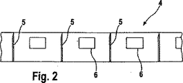
図1は、2つのローラ2、3を含むカセット1を示しており、該ローラ上には、図2に概略的に示された帯状のランセット担体4が巻かれている。これに関して、第1のローラ2は未使用のランセット5を有するランセット担体4の部分をもち、第2のローラ3はランセット担体4の使用済みの部分をもつ。図示されたカセット1が穿刺装置(図示せず)のカセット区画に挿入されると、ランセット担体4の使用済み部分が巻かれた第2のローラ3は、穿刺装置の漸次前進機構によって駆動されて、カセット1に含まれるランセット5を穿刺位置に順次移動させる。穿刺位置において、ランセット5は、穿刺装置の穿刺駆動部により穿刺動作が実行されると、ランセットに対して押圧された使用者の体部に穿刺傷を生成するように位置決めされ、ここから診断目的のための体液試料が採取され得る。漸次前進機構(図示せず)を作動させることによって、カセット1の駆動されたローラ3は、ランセット担体4の新しいランセット5が穿刺のための穿刺位置に達するまで回転時可能になる。
FIG. 1 shows a
図2によると、ランセット5は帯状のランセット担体上で担体の長手方向に対して横断するように配置される。2つのランセット5のあいだには、穿刺傷から採取された体液試料を試験するための1つの試験領域6がそれぞれ配置されている。検体濃度の光度測定のために、試験領域6は濃度依存性の呈色に影響する試験化学物質を含み得る。しかしながら、試験領域6を体液試料の電気化学的試験または分光試験用に構成することも可能である。
According to FIG. 2, the
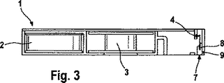
図1の平面図、図3および図4の側面図に示されるように、カセット1は連結手段7を有し、これに対してランセット担体4がもつランセット5が漸次前進機構の作動により可動となる。作動時には、連結手段7は、穿刺装置の穿刺駆動部を穿刺位置にあるランセット5に連結する。したがって、連結手段は、穿刺駆動部11によって穿刺中に生じた推進力を穿刺位置にあるランセット5に伝達可能である。図示された実施の形態において、連結手段7は穿刺装置の穿刺駆動部をランセット担体4に連結するため、ランセット担体4は、穿刺中に、穿刺位置にあるランセット5とともに移動する。
As shown in the plan view of FIG. 1 and the side views of FIGS. 3 and 4, the
連結手段7は、ランセット担体4のための容器8を有する。図示された実施例において、容器はスリット形状を有する。容器8は、カセット筐体に対して穿刺方向に推進可能な滑動子の一部をなす。容器8を介して、連結手段7はランセット担体4に永久的に連結される。したがって有利には、連結手段7は、漸次前進機構の作動中であっても穿刺駆動部に連結を保持されるため、漸次前進機構に対する機械的調整は不要である。
The connecting means 7 has a
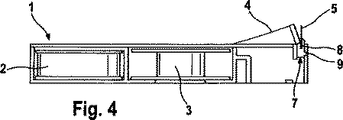
穿刺中に、連結手段7は、ランセット駆動部によって、前進段階にて穿刺方向に図3に示された位置から図4に示された位置まで推進され、後続の戻り動作において図3に示された位置に戻る。穿刺駆動部への連結のために、連結手段7は、図示された例示的な実施の形態においては杭状である連結要素9を有し、該連結要素は正嵌合により穿刺駆動部の適合する連結要素に係合する。
During puncturing, the connecting means 7 is propelled by the lancet drive in the advancing stage in the puncturing direction from the position shown in FIG. 3 to the position shown in FIG. 4 and is shown in FIG. Return to the previous position. For the connection to the puncture drive, the connection means 7 has a
連結された穿刺駆動部により穿刺中に生じた推進力は、スリット8内に位置するランセット担体4のテープ部分とともに、穿刺方向に連結手段7の移動を生じさせる。図示されておらず、また任意的にカセット上あるいは穿刺駆動部上に配置可能な曲げ機関は、図4に示されるように、ランセット担体テープ4の曲げを生じ得る。これによって、穿刺位置にあるランセット5の先端部は、帯状のランセット担体4の表面から離昇し、帯状のランセット担体4に妨げられることなく、これに接する使用者の体内に穿刺可能となる。曲げ機関は、たとえば穿刺方向に対して斜めに位置し、穿刺中にはそのあいだにランセットが突出する2本のフォーク突起の形状により供することができ、これによってフォーク突起部はランセット担体の帯を制止し、ランセットに隣接して両側に曲げる。
The propulsive force generated during puncturing by the connected puncturing drive unit causes the connecting means 7 to move in the puncturing direction together with the tape portion of the
穿刺後には、穿刺装置の漸次前進機構は、連結手段7のスリット8に帯状のランセット担体4の試験要素6を位置決めするために動作可能になる。穿刺駆動部を再度動作させることにより、試験領域6は、先行の穿刺により生成された穿刺傷まで移動可能となり、試験領域6は体液試料の採取が可能となる。
After puncturing, the gradual advancement mechanism of the puncturing device is operable to position the
図5は、上述の実施の形態の連結手段7の詳細を概略的に示す。図から明らかなように、スリット状に供された容器8の壁は、たとえば刺毛9などの斜め方向に位置する繊維により被覆される。刺毛9は、その自由端が戻り方向に対して斜めに向くように配置される。これにより、ランセット担体4は、連結手段7の戻り動作のあいだは刺毛9により保持され、これに連結する穿刺駆動部によって連結手段7とともにより引き込みが可能になる。したがって、図示された例示的な実施の形態において、連結手段7は、構造化された連結面を介してランセット担体4に接触し、該構造化された連結面は、相対運動方向に応じて連結面と対比してランセット担体4の相対運動に対する抵抗をもたらす。
FIG. 5 schematically shows details of the connecting means 7 of the above-described embodiment. As is apparent from the figure, the wall of the
構造面は戻り動作の方向のみに摩擦の増大をもたらすため、この種の連結面が漸次前進機構によるランセット担体4の移動をまったくあるいはほとんど妨げることはない。戻り動作中において、容器8の連結面の構造面、すなわち図示された例示的な実施の形態におけるスリット8の対向する側壁は、容器8内でランセット担体4の改善された密着性をもたらす。したがって、ランセット担体4は、連結手段7とともに、迅速に引き込み可能であり、またランセット担体4がもつランセット5は生成されたばかりの穿刺傷から引き込み可能である。
This kind of connecting surface does not obstruct the movement of the
このような有利な特性を有する構造面は、図4に示された繊維9のみならず、ランセット担体4の表面に接する容器8の連結面の他の突起部、隆起部または凹部によって得ることも可能である。
A structural surface having such advantageous characteristics can be obtained not only by the
図5による構造面は、たとえば、平行な短繊維による被覆により達成され得る。繊維9は固定層に固定される。繊維は、容器8の連結面に対して30°から90°のあいだ、好ましくは45°から75°のあいだの角度に配向される。これに関連して、繊維は、スリットの底方向、すなわち、図5に示されるとおり、戻り動作の方向と連結面8によりランセット担体4上に作用する力の方向とに傾斜する。
The structural surface according to FIG. 5 can be achieved, for example, by coating with parallel short fibers. The
この種の構造体の2つの連結面ランセット担体4の移動は、有利には、ほとんど摩擦なしに行われる。容器8への帯状のランセット担体4の挿入はまた、僅少な摩擦のみを生じる。しかしながら、繊維9の傾斜方向とは反対へのランセット担体4の移動を試みると、わずかな凹凸部分にも引っ掛かるため、ランセット担体4を制止させる。たとえば、フロック繊維フィルムが傾斜繊維9を有する構造連結面として使用可能であり、特に連結手段に接着させることにより連結手段に適用可能である。
The movement of the two connecting
適当なフロック繊維フィルムは、たとえば次のとおりに製造可能である。たとえば、ヴィースバーデンのMitsubishi Polyester Film社により製造されたホスタファンRN50のポリエステルフィルムが、たとえば、ドイツ国、ヴィースロッホのKissel+Wolf社製のMecoflock D453/5-09などの導電性接着剤で被覆される。その後、接着層は、ドイツ国、ゴマーリンゲンのMaag Flockmaschinen社製のEro-Miniフロッキング装置を用いて1.7dtexで長さ0.5mmのポリアミドフロックによりフロッキングされる。この種のフロックは、ドイツ国、シュトゥットガルトのSwissflock社から入手可能である。フロッキング直後において、フィルムは、たとえば360μmのロール間隔に設定されたカレンダを通って引っ張られる。これにより、繊維が斜めに配向される。乾燥後、フォロック層は真空にされて、ほつれた繊維を除去することにより清浄される。その後、繊維は巻き方向にポリエステルフィルムに対して約45°の角度を有する。繊維は、平均的に、巻き方向に対して垂直に配向される。 A suitable flock fiber film can be produced, for example, as follows. For example, a Hostafan RN50 polyester film manufactured by Mitsubishi Polyester Film, Wiesbaden, is coated with a conductive adhesive such as, for example, Mecoflock D453 / 5-09 from Kissel + Wolf, Wiesloch, Germany. The adhesive layer is then flocked with a polyamide flock of 0.5 dtex and a length of 0.5 mm using an Ero-Mini flocking device manufactured by Maag Flockmaschinen, Gomerlingen, Germany. This type of flock is available from Swissflock, Stuttgart, Germany. Immediately after flocking, the film is pulled through a calendar set at a roll spacing of, for example, 360 μm. Thereby, a fiber is orientated diagonally. After drying, the folock layer is evacuated and cleaned by removing frayed fibers. Thereafter, the fibers have an angle of about 45 ° to the polyester film in the winding direction. The fibers are, on average, oriented perpendicular to the winding direction.
適当なフロック繊維フィルムを製造する別の選択肢として、プラスチックフィルムをたとえば10mmの間隔で交互して上下に平行に折り曲げることがあり、これによって曲げ部分は、それぞれ100°〜140°、たとえば120°の角度を有する。その後、フロックは前述の例と同様にフィルムに適用されるが、その後、フィルムはロール間を通って移動しない。これは、フィルム部分の傾斜によって繊維が接着剤に急送されることで、フィルムに対して約60〜70°の角度で位置決めされるためである。 Another option for producing a suitable flock fiber film is to fold the plastic film alternately in parallel up and down at intervals of 10 mm, for example, so that the bends are 100 ° to 140 °, for example 120 °, respectively. Have an angle. The floc is then applied to the film as in the previous example, but after that the film does not move between the rolls. This is because the fibers are rapidly sent to the adhesive by the inclination of the film portion, so that the fibers are positioned at an angle of about 60 to 70 ° with respect to the film.
図5に示された連結手段7の溝は、たとえば0.8mmの幅を有し得る。フロック繊維フィルムは、たとえばエポキシ接着剤を使用してスリットの壁に接着可能であり、図5によると、これにより繊維9がスリット底部方向に指向する。
The groove of the connecting means 7 shown in FIG. 5 can have a width of, for example, 0.8 mm. The flock fiber film can be adhered to the slit wall using, for example, an epoxy adhesive, and according to FIG. 5, this directs the
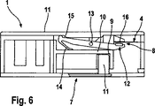
図6は、連結手段7を有するカセット1の別の例示的実施の形態を示す。図1に示されたカセット1と同様に、図6に示されたカセット1は、図2にしたがった配置の複数のランセット5を有する帯状ランセット担体4を含む。このカセット1は、上述の前の実施の形態とは基本的に連結手段7の設計が異なるのみであり、作動時に、連結手段は、穿刺中に穿刺駆動部から生じた推進力を穿刺位置にあるランセット5に伝達するために、穿刺装置の穿刺駆動部をランセット担体4に連結する。
FIG. 6 shows another exemplary embodiment of the
連結手段7は、カセット筐体11に対して移動可能なように位置する滑動子10を備える。滑動子10は、穿刺装置の穿刺駆動部に連結するための連結要素として、杭により穿刺駆動部11と係合する凹所9を有し、これにより、滑動子10は穿刺駆動部11により生成された推進力によって穿刺方向に移動可能となる。
The connecting means 7 includes a
ランセット担体4への連結のために、図示された連結手段7は容器8を有しており、これを通ってランセット担体4が案内される。容器8は、滑動子10と、連結面16に対して可動で、穿刺中に容器内にランセット担体4を固締して穿刺後の戻り動作の完了後に再度解放する押圧要素12との上に固着配置された連結面16によって形成される。
For connection to the
押圧要素12は滑動子10上に配置されることにより、回動点13の周りに回動可能である。ばね要素14は、図示された実施の形態においてカセット筐体11に統合された接続部材15に対して押圧要素12の後端部を押圧する。滑動子10を穿刺方向に移動することにより、押圧要素12の後端部は接続部材15に沿って走行し、この配置によって回動可能であって、前端部を滑動子10の連結面16に対して押圧する閉動作を実行でき、よって、ランセット担体4は連結面16と押圧要素12の前端部とのあいだに固締される。これによって、図示された例示の実施の形態の連結手段7は、穿刺中に固締様式でランセット担体4を把持し、穿刺後の戻り動作完了後には再度これを解放する。容器8内でのランセット担体4の固締は、ランセット担体4が、戻り動作中に迅速で確実に戻ることを可能にし、これによって担体に担持されたランセットは生成された穿刺傷から迅速に引き抜かれる。このことは、穿刺ができる限り少ない痛みを伴うことに関連して重要である。
The
図示された実施の形態において、ランセット担体4を固締するための固締力は、接続部材15に対する押圧要素12の後端部を押圧するばね要素14によってもたらされ、接続部材は穿刺動作中に押圧要素12の閉動作を画定する。
In the illustrated embodiment, the clamping force for clamping the
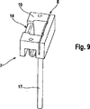
図7〜9は、連結手段7の別の実施の形態を示しており、該連結手段は、たとえば図1または6のカセット1の場合において、上述の先の連結手段7の代わりに使用可能である。図6に示された連結手段7に類似して、図7〜9に示された連結手段7は、穿刺中にランセット担体4を固締式で把持し、穿刺後の戻り動作完了後には再度これを解放する。したがって、図7は、穿刺前の解放されたランセット担体4を有する連結手段7を示す。図8において、ランセット担体4は連結手段7によって固締され、明確な穿刺中の状態が示されている。図9は、図7および8に示された連結手段7の一部に関する斜位図を示す。
FIGS. 7 to 9 show another embodiment of the connecting means 7, which can be used instead of the previous connecting means 7 described above, for example in the case of the
図6に示された実施の形態と同様に、図7〜9に示された実施の形態の連結手段7は、穿刺方向に推進可能な滑動子10を備え、これを通ってランセット担体4が供給される容器8を有する。図8において穿刺方向は点線で示される。ランセット担体4の容器8は、たとえばスロット状に供され得る。
Similar to the embodiment shown in FIG. 6, the connecting means 7 of the embodiment shown in FIGS. 7-9 comprises a
容器8は、穿刺中に容器8の連結面に対してランセット担体4を押圧し、これを固締する押圧要素12と相互作用する。ランセット担体4を固締するための固締力は、図示された実施の形態において押圧要素12と同一の構成要素により供されるばね要素14によってもたらされる。ばね要素14は、図示された実施の形態においてカセット筐体(図示せず)に対して固定位置に配置されたオープナー17と相互に作用し、たとえば、カセット筐体上に突起状に供され得る。
The
滑動子10が穿刺前に図7に示された開始位置にある場合、オープナー17はばね要素14を押圧し、これによって容器8が開く。その後、ランセット担体4は、漸次前進機構(図示せず)を作動させることで、容器8内にて穿刺方向に対して垂直に移動可能となる。滑動子10を穿刺方向に移動させることにより、ばね要素14はオープナー17から離間し、これによって容器8内にてランセット担体4を固締する。これにより、ばね要素14により作用するばね力が、ランセット担体4を容器8の連結面に対して押圧する。
When the
ばね要素14は、プラスチック材から安価に製造可能である。しかしながら、ばね要素14を金属で製造することも可能である。
The
図10は、体液試料を採取するための穿刺装置の実施の形態を示す。穿刺装置20は、穿刺傷を生成するために体部に押圧される開口部21を有する。穿刺装置20は、カギ状の作動要素22と、試験結果を表示するための液晶表示装置式の表示機器23をさらに備える。穿刺装置20は、複数のランセット5をもつランセット担体4を含むカセット1を受け取るための区画(図示せず)を有する。この種のカセット1の例示的実施の形態は、図1〜9により説明した。図示された穿刺装置20の区画は、閉じることが可能な開口部を有し、図示された穿刺装置20の後側に配置される。
FIG. 10 shows an embodiment of a puncture device for collecting a body fluid sample. The
測定および分析機関(図示せず)は、図示された穿刺装置20に統合され、体液試料の検体濃度を測定するために使用可能である。この目的のために、穿刺傷の生成後に挿入されたカセット1(図2を参照)に包含されたランセット担体帯4の試験領域6によって取り込まれる。試料の採取は、漸次前進機構を作動させることによって、ランセット担体帯4の試験領域6を装置開口部21の下方に位置決めすることにより行われる。穿刺駆動部を再度動作させることで、試験領域6を有するランセット担体4が穿刺方向に移動可能となり、これによって、体液試料を取り込むために装置開口部21に対して押圧された体部の穿刺傷に対して試験領域6が配される。
A measurement and analysis facility (not shown) is integrated into the illustrated lancing
図10に示された穿刺装置および図1〜9を参照して説明したカセット1は、総合して穿刺システムを形成する。
The puncture device shown in FIG. 10 and the
1 カセット
2 ローラ
3 ローラ
4 ランセット担体
5 ランセット
6 試験領域
7 連結手段
8 ランセット担体用の容器
9 連結要素/刺毛
10 滑動子
11 穿刺駆動部
12 押圧要素
13 回動点
14 ばね要素
15 接続部材
16 連結面
17 オープナー
20 穿刺装置
21 装置開口部
22 作動要素
23 表示機器
DESCRIPTION OF
Claims (13)
複数のランセット(5)をもつランセット担体(4)を含む少なくとも1つのカセット(1)と、このようなカセット(1)のための区画、区画に挿入されたカセット(1)内に含まれたランセット(5)を連続して穿刺位置に移動するための漸次前進機構、および穿刺位置にあるランセット(5)を穿刺動作のために加速させる穿刺駆動部(11)を有する穿刺装置とを備えた穿刺システムであって、
前記カセット(1)が、ランセット担体(4)のための容器(8)を有する連結手段(7)を有し、前記容器(8)が、カセット筐体(11)に対して可動であり、ランセット担体(4)がもつ前記ランセット(5)が、漸次前進機構を作動させることによって容器(8)に対して可動になり、容器(8)が、作動時に、穿刺駆動部(11)を穿刺位置にあるランセット(5)に連結し、穿刺駆動部(11)により生成された推進力を穿刺中に穿刺位置にあるランセット(5)に伝達し、
前記ランセット(5)が、ランセット担体(4)の長手方向に対して横断するように配置されることを特徴とする穿刺システム。A puncture system for collecting a body fluid sample,
At least one cassette (1) comprising a lancet carrier (4) with a plurality of lancets (5) and a compartment for such a cassette (1), contained in a cassette (1) inserted into the compartment A gradual advance mechanism for continuously moving the lancet (5) to the puncture position, and a puncture device having a puncture drive unit (11) for accelerating the lancet (5) at the puncture position for the puncture operation A puncture system,
The cassette (1) has connecting means (7) having a container (8) for the lancet carrier (4), the container (8) being movable relative to the cassette housing (11); The lancet (5) of the lancet carrier (4) becomes movable with respect to the container (8) by gradually operating the advance mechanism, and the container (8) punctures the puncture drive unit (11) when activated. Connected to the lancet (5) at the position, and transmitting the propulsive force generated by the puncture drive unit (11) to the lancet (5) at the puncture position during puncturing ,
Puncture system wherein the lancet (5), is arranged so as to cross the longitudinal direction of the lancet carrier (4), characterized in Rukoto.
前記ランセット(5)が、ランセット担体(4)の長手方向に対して横断するように配置されることを特徴とするカセット。A cassette for a puncture device for collecting a bodily fluid sample, the cassette (1) comprising a lancet carrier (4) having a plurality of lancets (5) and also for cassettes (1) for puncturing operations The cassette (1) connects the lancet carrier (4) to the puncture drive unit (11) of the puncture device, which can be inserted into the puncture device including the puncture drive unit (11) for accelerating the included lancet (5). Connecting means (7) for connecting the container (8) to the cassette housing (11), the connecting means (7) having a container (8) for the lancet carrier (4). In contrast, the container (8) transmits a propulsive force to the lancet (5) in which the container (8) is at the puncture position, and the propulsive force is generated during puncture by the puncture drive unit (11) connected to the container (8) It is,
Cassette wherein the lancet (5), is arranged so as to cross the longitudinal direction of the lancet carrier (4), characterized in Rukoto.
前記ランセット(5)が、ランセット担体(4)の長手方向に対して横断するように配置されることを特徴とする穿刺装置。A puncture device for collecting a bodily fluid sample having a compartment for a cassette (1), the compartment comprising a lancet carrier (4) having a plurality of lancets (5) and a cassette ( A gradual advance mechanism for sequentially positioning the lancet (5) included in 1) at the puncture position, and a puncture drive unit (11) for accelerating the lancet (5) at the puncture position, The lancet drive (11) is configured to be connected to the lancet carrier (4) via the connecting means (7) of the inserted cassette (1), and the lancet (5) is in the puncture position for puncturing. to accelerate,
Lancing device wherein the lancet (5), is arranged so as to cross the longitudinal direction of the lancet carrier (4), characterized in Rukoto.
Applications Claiming Priority (3)
| Application Number | Priority Date | Filing Date | Title |
|---|---|---|---|
| EP07007470A EP1980205A1 (en) | 2007-04-12 | 2007-04-12 | Piercing system |
| EP07007470.3 | 2007-04-12 | ||
| PCT/EP2008/002172 WO2008125178A1 (en) | 2007-04-12 | 2008-03-19 | Piercing system |
Publications (2)
| Publication Number | Publication Date |
|---|---|
| JP2010523235A JP2010523235A (en) | 2010-07-15 |
| JP5114549B2 true JP5114549B2 (en) | 2013-01-09 |
Family
ID=38330789
Family Applications (1)
| Application Number | Title | Priority Date | Filing Date |
|---|---|---|---|
| JP2010502432A Expired - Fee Related JP5114549B2 (en) | 2007-04-12 | 2008-03-19 | Puncture system |
Country Status (10)
| Country | Link |
|---|---|
| US (1) | US8945022B2 (en) |
| EP (2) | EP1980205A1 (en) |
| JP (1) | JP5114549B2 (en) |
| CN (1) | CN101657157B (en) |
| CA (1) | CA2680855C (en) |
| ES (1) | ES2447039T3 (en) |
| HK (1) | HK1139577A1 (en) |
| MX (1) | MX2009007933A (en) |
| PL (1) | PL2134258T3 (en) |
| WO (1) | WO2008125178A1 (en) |
Families Citing this family (4)
| Publication number | Priority date | Publication date | Assignee | Title |
|---|---|---|---|---|
| EP2221001A1 (en) * | 2009-02-18 | 2010-08-25 | Roche Diagnostics GmbH | Handheld analysis tool |
| EP2316338A1 (en) | 2009-11-02 | 2011-05-04 | Roche Diagnostics GmbH | Lancet hook for use in a lancet device |
| WO2018051493A1 (en) * | 2016-09-16 | 2018-03-22 | 富士通株式会社 | Electronic device and method for manufacturing electronic device |
| EP3656303B1 (en) * | 2018-11-22 | 2021-06-30 | Roche Diabetes Care GmbH | Blood withdrawal system with lancet ejection mechanism |
Family Cites Families (14)
| Publication number | Priority date | Publication date | Assignee | Title |
|---|---|---|---|---|
| US3716292A (en) * | 1970-11-16 | 1973-02-13 | Advance Management Eng & Res C | Film advancing device |
| DE2803345C2 (en) * | 1978-01-26 | 1980-02-14 | Emil 7507 Pfinztal Eisinger | Blood sampling device |
| US5514152A (en) * | 1994-08-16 | 1996-05-07 | Specialized Health Products, Inc. | Multiple segment encapsulated medical lancing device |
| ATE414469T1 (en) * | 2001-06-08 | 2008-12-15 | Hoffmann La Roche | EXTRACTION DEVICE FOR BODY FLUIDS |
| US7041068B2 (en) * | 2001-06-12 | 2006-05-09 | Pelikan Technologies, Inc. | Sampling module device and method |
| US7297122B2 (en) * | 2002-04-19 | 2007-11-20 | Pelikan Technologies, Inc. | Method and apparatus for penetrating tissue |
| US20030211619A1 (en) * | 2002-05-09 | 2003-11-13 | Lorin Olson | Continuous strip of fluid sampling and testing devices and methods of making, packaging and using the same |
| WO2005018711A2 (en) | 2003-08-20 | 2005-03-03 | Facet Technologies, Llc | Lancing device with multi-lancet magazine |
| US7909776B2 (en) * | 2004-04-30 | 2011-03-22 | Roche Diagnostics Operations, Inc. | Lancets for bodily fluid sampling supplied on a tape |
| US8591436B2 (en) * | 2004-04-30 | 2013-11-26 | Roche Diagnostics Operations, Inc. | Lancets for bodily fluid sampling supplied on a tape |
| KR101120451B1 (en) * | 2007-01-13 | 2012-02-29 | 에프. 호프만-라 로슈 아게 | Pricking device |
| EP1967139A1 (en) * | 2007-03-09 | 2008-09-10 | Roche Diagnostics GmbH | Disposable puncturing device and resuable handling device for a puncturing device |
| EP1974667A1 (en) * | 2007-03-29 | 2008-10-01 | Roche Diagnostics GmbH | Piercing system |
| ATE535189T1 (en) * | 2009-04-03 | 2011-12-15 | Hoffmann La Roche | DEVICE FOR COLLECTING AND ANALYZING A BLOOD SAMPLE |
-
2007
- 2007-04-12 EP EP07007470A patent/EP1980205A1/en not_active Withdrawn
-
2008
- 2008-03-19 CN CN2008800116443A patent/CN101657157B/en not_active Expired - Fee Related
- 2008-03-19 PL PL08734654T patent/PL2134258T3/en unknown
- 2008-03-19 ES ES08734654.0T patent/ES2447039T3/en active Active
- 2008-03-19 JP JP2010502432A patent/JP5114549B2/en not_active Expired - Fee Related
- 2008-03-19 EP EP08734654.0A patent/EP2134258B1/en not_active Not-in-force
- 2008-03-19 MX MX2009007933A patent/MX2009007933A/en not_active Application Discontinuation
- 2008-03-19 CA CA2680855A patent/CA2680855C/en not_active Expired - Fee Related
- 2008-03-19 WO PCT/EP2008/002172 patent/WO2008125178A1/en active Application Filing
-
2009
- 2009-10-12 US US12/577,570 patent/US8945022B2/en not_active Expired - Fee Related
-
2010
- 2010-06-14 HK HK10105935.5A patent/HK1139577A1/en not_active IP Right Cessation
Also Published As
| Publication number | Publication date |
|---|---|
| PL2134258T3 (en) | 2014-05-30 |
| CA2680855C (en) | 2017-04-25 |
| ES2447039T3 (en) | 2014-03-11 |
| EP1980205A1 (en) | 2008-10-15 |
| MX2009007933A (en) | 2009-07-31 |
| US8945022B2 (en) | 2015-02-03 |
| US20100049092A1 (en) | 2010-02-25 |
| CN101657157A (en) | 2010-02-24 |
| EP2134258A1 (en) | 2009-12-23 |
| CA2680855A1 (en) | 2008-10-23 |
| JP2010523235A (en) | 2010-07-15 |
| CN101657157B (en) | 2011-10-05 |
| EP2134258B1 (en) | 2013-12-11 |
| HK1139577A1 (en) | 2010-09-24 |
| WO2008125178A1 (en) | 2008-10-23 |
Similar Documents
| Publication | Publication Date | Title |
|---|---|---|
| US8758382B2 (en) | Lancet magazine | |
| US7226461B2 (en) | Method and apparatus for a multi-use body fluid sampling device with sterility barrier release | |
| KR100941898B1 (en) | Lancets for bodily fluid sampling supplied on a tape | |
| EP1653849B1 (en) | Method and apparatus for body fluid sampling with integrated analyte detecting member | |
| US7297151B2 (en) | Method and apparatus for body fluid sampling with improved sensing | |
| US9364172B2 (en) | System for collecting samples and method for collecting a liquid sample | |
| US7771367B2 (en) | Lancet wheel | |
| KR101120451B1 (en) | Pricking device | |
| US9017620B2 (en) | Combination drive for a sampling system for collecting a liquid sample | |
| KR101175967B1 (en) | Analytical system for determining an analyte in a body fluid and disposable integrated sample collection and analytical element | |
| CN101313851A (en) | Flexible lancet | |
| JP5114549B2 (en) | Puncture system | |
| CA2754857C (en) | Modified lancet carrier for single-use lancet sensor assembly | |
| KR101104658B1 (en) | Piercing system |
Legal Events
| Date | Code | Title | Description |
|---|---|---|---|
| RD03 | Notification of appointment of power of attorney |
Free format text: JAPANESE INTERMEDIATE CODE: A7423 Effective date: 20100525 |
|
| A621 | Written request for application examination |
Free format text: JAPANESE INTERMEDIATE CODE: A621 Effective date: 20110214 |
|
| TRDD | Decision of grant or rejection written | ||
| A01 | Written decision to grant a patent or to grant a registration (utility model) |
Free format text: JAPANESE INTERMEDIATE CODE: A01 Effective date: 20120925 |
|
| A01 | Written decision to grant a patent or to grant a registration (utility model) |
Free format text: JAPANESE INTERMEDIATE CODE: A01 |
|
| A977 | Report on retrieval |
Free format text: JAPANESE INTERMEDIATE CODE: A971007 Effective date: 20120928 |
|
| A61 | First payment of annual fees (during grant procedure) |
Free format text: JAPANESE INTERMEDIATE CODE: A61 Effective date: 20121015 |
|
| FPAY | Renewal fee payment (event date is renewal date of database) |
Free format text: PAYMENT UNTIL: 20151019 Year of fee payment: 3 |
|
| R150 | Certificate of patent or registration of utility model |
Ref document number: 5114549 Country of ref document: JP Free format text: JAPANESE INTERMEDIATE CODE: R150 Free format text: JAPANESE INTERMEDIATE CODE: R150 |
|
| R250 | Receipt of annual fees |
Free format text: JAPANESE INTERMEDIATE CODE: R250 |
|
| R250 | Receipt of annual fees |
Free format text: JAPANESE INTERMEDIATE CODE: R250 |
|
| R250 | Receipt of annual fees |
Free format text: JAPANESE INTERMEDIATE CODE: R250 |
|
| R250 | Receipt of annual fees |
Free format text: JAPANESE INTERMEDIATE CODE: R250 |
|
| R250 | Receipt of annual fees |
Free format text: JAPANESE INTERMEDIATE CODE: R250 |
|
| R250 | Receipt of annual fees |
Free format text: JAPANESE INTERMEDIATE CODE: R250 |
|
| LAPS | Cancellation because of no payment of annual fees |