JP5114207B2 - Vane bearing ring of turbocharger for automobile internal combustion engine - Google Patents
Vane bearing ring of turbocharger for automobile internal combustion engine Download PDFInfo
- Publication number
- JP5114207B2 JP5114207B2 JP2007547154A JP2007547154A JP5114207B2 JP 5114207 B2 JP5114207 B2 JP 5114207B2 JP 2007547154 A JP2007547154 A JP 2007547154A JP 2007547154 A JP2007547154 A JP 2007547154A JP 5114207 B2 JP5114207 B2 JP 5114207B2
- Authority
- JP
- Japan
- Prior art keywords
- bearing ring
- turbocharger
- vane
- combustion engine
- internal combustion
- Prior art date
- Legal status (The legal status is an assumption and is not a legal conclusion. Google has not performed a legal analysis and makes no representation as to the accuracy of the status listed.)
- Expired - Fee Related
Links
Images


Classifications
-
- F—MECHANICAL ENGINEERING; LIGHTING; HEATING; WEAPONS; BLASTING
- F01—MACHINES OR ENGINES IN GENERAL; ENGINE PLANTS IN GENERAL; STEAM ENGINES
- F01D—NON-POSITIVE DISPLACEMENT MACHINES OR ENGINES, e.g. STEAM TURBINES
- F01D17/00—Regulating or controlling by varying flow
- F01D17/10—Final actuators
- F01D17/12—Final actuators arranged in stator parts
- F01D17/14—Final actuators arranged in stator parts varying effective cross-sectional area of nozzles or guide conduits
- F01D17/16—Final actuators arranged in stator parts varying effective cross-sectional area of nozzles or guide conduits by means of nozzle vanes
- F01D17/165—Final actuators arranged in stator parts varying effective cross-sectional area of nozzles or guide conduits by means of nozzle vanes for radial flow, i.e. the vanes turning around axes which are essentially parallel to the rotor centre line
-
- F—MECHANICAL ENGINEERING; LIGHTING; HEATING; WEAPONS; BLASTING
- F01—MACHINES OR ENGINES IN GENERAL; ENGINE PLANTS IN GENERAL; STEAM ENGINES
- F01D—NON-POSITIVE DISPLACEMENT MACHINES OR ENGINES, e.g. STEAM TURBINES
- F01D5/00—Blades; Blade-carrying members; Heating, heat-insulating, cooling or antivibration means on the blades or the members
- F01D5/12—Blades
- F01D5/28—Selecting particular materials; Particular measures relating thereto; Measures against erosion or corrosion
-
- F—MECHANICAL ENGINEERING; LIGHTING; HEATING; WEAPONS; BLASTING
- F02—COMBUSTION ENGINES; HOT-GAS OR COMBUSTION-PRODUCT ENGINE PLANTS
- F02B—INTERNAL-COMBUSTION PISTON ENGINES; COMBUSTION ENGINES IN GENERAL
- F02B37/00—Engines characterised by provision of pumps driven at least for part of the time by exhaust
- F02B37/12—Control of the pumps
- F02B37/24—Control of the pumps by using pumps or turbines with adjustable guide vanes
-
- F—MECHANICAL ENGINEERING; LIGHTING; HEATING; WEAPONS; BLASTING
- F05—INDEXING SCHEMES RELATING TO ENGINES OR PUMPS IN VARIOUS SUBCLASSES OF CLASSES F01-F04
- F05D—INDEXING SCHEME FOR ASPECTS RELATING TO NON-POSITIVE-DISPLACEMENT MACHINES OR ENGINES, GAS-TURBINES OR JET-PROPULSION PLANTS
- F05D2220/00—Application
- F05D2220/40—Application in turbochargers
Landscapes
- Engineering & Computer Science (AREA)
- Mechanical Engineering (AREA)
- General Engineering & Computer Science (AREA)
- Chemical & Material Sciences (AREA)
- Materials Engineering (AREA)
- Supercharger (AREA)
- Turbine Rotor Nozzle Sealing (AREA)
- Sliding-Contact Bearings (AREA)
Description
本発明は、請求項1〜3に記載した形式の、調節可能なタービンベーンを備えたターボチャージャのベーン支承リング(Schaufellagerring)に関する。つまり本発明は、自動車内燃機関の、可変のタービンジオメトリを有するターボチャージャのベーン支承リングであって、ターボチャージャが、可変のタービンジオメトリのために、ベーン支承リング内で調節可能なタービンベーンを有しており、ベーン支承リングが、その支承面での固体潤滑剤作用を達成するための硫黄成分を有するオーステナイト系の鉄マトリックス合金から成っている形式のものに関する。
The invention relates to a turbocharger vane bearing ring with adjustable turbine vanes of the type as defined in
欧州特許出願公開第1394364号明細書から、2つのベーン支承リングを備えるターボチャージャが公知である。製作コストを減じることができるように、少なくとも一方のベーン支承リングは、その面周方向にわたって分配され一体的に成形されたスペーサを有する。これらのスペーサにより、両ベーン支承リングの軸方向の間隔は確保可能である。
欧州特許出願公開第1396620号明細書から、ベーン支承リングを備える別のターボチャージャが公知である。
最近の高出力エンジンにおいて、耐久的に機能を果たし得るベーン支承リングには、極めて高い材料要求が課される。相応に適した材料は、十分なクリープ抵抗、高温時でもベーン支承リングの熱的なひずみを回避する高い寸法安定性、高い耐摩耗性ならびに十分な耐酸化性を有していなければならない。上位概念部に記載した形式のベーン支承リングのひずみ、クリープまたは強い酸化が生じると、タービンガイドベーンのロック、つまり固着に至り得る。すなわち、ターボチャージャ横断面はもはやガイドベーン調節によりエンジンの運転状態に適合され得ない。
From European Patent Application No. 1394364, a turbocharger with two vane bearing rings is known. In order to reduce manufacturing costs, at least one of the vane bearing rings has a spacer that is distributed and integrally molded over its circumferential direction. With these spacers, it is possible to ensure an axial distance between the two vane support rings.
From EP 1396620 another turbocharger with a vane bearing ring is known.
In modern high power engines, extremely high material requirements are imposed on vane bearing rings that can perform durablely. A correspondingly suitable material must have sufficient creep resistance, high dimensional stability to avoid thermal distortion of the vane bearing ring even at high temperatures, high wear resistance and sufficient oxidation resistance. Strain, creep or strong oxidation of the vane bearing ring of the type described in the superordinate concept can lead to turbine guide vane locking, i.e., sticking. That is, the turbocharger cross-section can no longer be adapted to the engine operating conditions by adjusting the guide vanes.
ベーン支承リングとして、従来、主に高い割合のクロムおよびクロムカーバイドを含有するフェライト系の材料が使用される。熱的により高く負荷されるベーン支承リングでは、クロムカーバイドを含有するオーステナイト系の材料が使用される。この種の合金は例えば、それぞれ質量%で示す以下の成分を含有する:C=0.4〜0.7、Cr=18〜21、Ni=12〜14、S=0.2〜0.4、Si=1.8〜2.2(残りとしての鉄と3%までの不特定の合金成分もしくは不純物とを有する)。そのような合金は以下合金PL23と呼ぶ。 Conventionally, ferrite-based materials containing a high proportion of chromium and chromium carbide are used as the vane bearing ring. For vane bearing rings, which are more thermally loaded, austenitic materials containing chromium carbide are used. This type of alloy contains, for example, the following components, each represented by mass%: C = 0.4 to 0.7, Cr = 18 to 21, Ni = 112 to 14, S = 0.2 to 0.4. Si = 1.8-2.2 (with remaining iron and up to 3% unspecified alloy components or impurities). Such an alloy is hereinafter referred to as alloy PL23.
本発明の課題は、上位概念部に記載した形式のベーン支承リングを、材料に関して、極度に高い温度での使用のために機能信頼性に設計することである。特に850℃を上回る温度での高いクリープ抵抗および高い強度の達成に努める。特にこのような高い温度時、上位概念部に記載した形式のベーン支承リング内でのタービンベーンの可動性は完全に保証されているべきである。 The object of the present invention is to design a vane bearing ring of the type described in the superordinate concept part with functional reliability for use at extremely high temperatures in terms of materials. In particular, strive to achieve high creep resistance and high strength at temperatures above 850 ° C. Especially at such high temperatures, the mobility of the turbine vanes in the vane bearing ring of the type described in the superordinate concept should be completely guaranteed.
この課題は、請求項1の特徴部に記載した合金組成、つまり該鉄マトリックス合金が、質量%で、炭素(C):0.4〜0.6%、クロム(Cr):18〜27%、ニッケル(Ni):12〜22%、硫黄(S):0.2〜0.5%およびケイ素(Si):2.9〜3.2%を含有し、さらに、タングステン(W):2.4〜2.8%および/またはニオブ(Nb):1.4〜1.8%を含有し、残部が鉄および不純物からなる、上位概念部に記載した形式のベーン支承リングにより解決される。
The problem is that the alloy composition described in the characterizing portion of
特に有利なベーン支承リングを構成するオーステナイト系の鉄マトリックス合金は、請求項2に記載した合金、つまりそれぞれ質量%で示す個々の合金元素を有する次の合金組成、質量%で、炭素(C):0.4〜0.6%、クロム(Cr):18.5〜20.5%、ニッケル(Ni):12.5〜14%、硫黄(S):0.25〜0.45%およびケイ素(Si):2.9〜3.15%を含有し、さらに、タングステン(W):2.4〜2.8%および/またはニオブ(Nb):1.4〜1.8%を含有し、残部が鉄および不純物からなるか、あるいは、請求項3に記載した合金、つまりそれぞれ質量%で示す個々の合金元素を有する次の合金組成、質量%で、炭素(C):0.4〜0.6%、クロム(Cr):24.5〜26.5%、ニッケル(Ni):19.5〜21.5%、硫黄(S):0.25〜0.45%およびケイ素(Si):2.9〜3.15%を含有し、さらに、タングステン(W):2.4〜2.8%および/またはニオブ(Nb):1.4〜1.8%を含有し、残部が鉄および不純物からなる合金であることが、特に良好な解決策であることが判った。 An austenitic iron matrix alloy which constitutes a particularly advantageous vane bearing ring is the alloy according to claim 2 , that is to say carbon (C) with the following alloy composition, each by mass%, each having an individual alloy element expressed in mass%: : 0.4-0.6%, chromium (Cr): 18.5-20.5%, nickel (Ni): 12.5-14%, sulfur (S): 0.25-0.45% and Silicon (Si): 2.9 to 3.15%, tungsten (W): 2.4 to 2.8% and / or niobium (Nb): 1.4 to 1.8% And the balance consists of iron and impurities, or the alloy according to claim 3 , that is, the following alloy composition, each having an individual alloy element expressed in% by mass, with carbon (C): 0.4% -0.6%, chromium (Cr): 24.5-26.5%, d Kell (Ni): 19.5 to 21.5%, Sulfur (S): 0.25 to 0.45% and Silicon (Si): 2.9 to 3.15%, and further containing tungsten (W ): 2.4-2.8% and / or niobium (Nb): 1.4-1.8%, with the balance being an alloy consisting of iron and impurities is a particularly good solution I found out.
本発明は、出力向上されるエンジンにおいてベーン支承リング材料の特に耐クリープ性および強度に対する高められた要求を、固体の潤滑剤特性をもたらす硫黄成分を有し、高融点の合金元素が添加されているオーステナイト系の鉄材料により充足するという一般的な思想に基づく。その際、これらの合金元素は単独でまたは複数のこれらの元素の存在時に、少なくとも1質量パーセント〜6質量パーセントの質量割合を占めるべきである。 The present invention provides an increased demand for especially creep resistance and strength of vane bearing ring materials in engines with improved power, with the addition of a high melting point alloying element having a sulfur component that provides solid lubricant properties. It is based on the general idea of being satisfied with existing austenitic iron materials. In this case, these alloy elements should occupy a mass proportion of at least 1 mass percent to 6 mass percent, alone or in the presence of a plurality of these elements.
ベーン支承リング材料の、本発明により達成可能な高められた耐クリープ性は、より高い温度時に、ベーン支承リングの高い寸法安定性を生む。合金中の硫黄成分に由来する固体潤滑剤作用により、良好な潤滑が、特にベーン支承リングとこのベーン支承リング内に支承されたタービンベーンとの間の接触面に生じる。本発明による材料使用時、タービンベーン、すなわちガイドベーンのロックは高温時に確実に回避される。 The enhanced creep resistance achievable by the present invention of the vane bearing ring material results in higher dimensional stability of the vane bearing ring at higher temperatures. Due to the solid lubricant action originating from the sulfur component in the alloy, good lubrication occurs, particularly at the contact surface between the vane bearing ring and the turbine vane supported in the vane bearing ring. When using the material according to the invention, the locking of the turbine vanes, ie guide vanes, is reliably avoided at high temperatures.
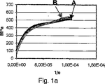
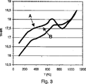
図面には、本発明によるベーン支承リング材料のための幾つかの特性グラフが示されている。個々のグラフに示した曲線は、Aが付されていれば、請求項2に記載した材料に該当し、Bが付されていれば、請求項3に記載した材料に該当する。 In the drawing, several characteristic graphs for a vane bearing ring material according to the invention are shown. The curve shown in each graph corresponds to the material described in claim 2 if A is attached, and corresponds to the material described in claim 3 if B is attached.
個々のグラフの説明
図1a,1b
これらのグラフは、段階的な負荷時の合金A,Bのクリープ特性を示している。この試験では、2MPaずつ、35秒の保持時間が与えられており、保持時間の最後の5秒のクリープ率が測定されている。図1aは700℃でのクリープ特性を示しており、図1bは900℃でのクリープ特性を示している。
Explanation of individual graphs FIGS. 1a and 1b
These graphs show the creep characteristics of Alloys A and B under stepwise loading. In this test, a holding time of 35 seconds is given every 2 MPa, and the creep rate of the last 5 seconds of the holding time is measured. FIG. 1 a shows the creep characteristics at 700 ° C., and FIG. 1 b shows the creep characteristics at 900 ° C.
図2
このグラフには、温度に依存した合金A,Bの弾性率(Elastizitaetsmodul:E−Modul)ならびに剛性率(Schubmodul:G−Modul)が記載されている。
FIG.
In this graph, the elastic modulus (Elastizitatsmodul: E-Modul) and the rigidity (Schubmodul: G-Modul) of the alloys A and B depending on temperature are described.
図3
このグラフは、温度に依存した合金A,Bの熱膨張係数を示している。
FIG.
This graph shows the thermal expansion coefficients of alloys A and B depending on the temperature.
図4
このグラフには、縦軸に、温度に依存した合金A,Bの高温硬さ(HV10)が記載されている。
FIG.
In this graph, the vertical axis indicates the high temperature hardness (HV10) of alloys A and B depending on the temperature.
図5
縦軸には、それぞれ2時間の保管および空冷後の、温度に依存した合金A,Bの硬さ(HB2.5/187.5)が示されている。
FIG.
The vertical axis shows the temperature-dependent hardness of alloys A and B (HB2.5 / 187.5) after storage for 2 hours and air cooling, respectively.
図6
この図は、合金A,Bに関してそれぞれ室温で、ρ=密度、λ=熱伝導度、Rp02=弾性限度、Rm=引張強さ、E=弾性率の値が記載されている表である。
FIG.
This figure is a table in which values of ρ = density, λ = thermal conductivity, R p02 = elastic limit, R m = tensile strength, E = elastic modulus are described for alloys A and B at room temperature, respectively. .
明細書および特許請求の範囲に記載したすべての特徴は、個別的にも、互いに組み合わされた任意の形態でも本発明の本質を成すものであり得る。 All of the features described in the description and the claims may form the essence of the present invention individually or in any form combined with each other.
Claims (3)
該鉄マトリックス合金が、質量%で、炭素(C):0.4〜0.6%、クロム(Cr):18〜27%、ニッケル(Ni):12〜22%、硫黄(S):0.2〜0.5%およびケイ素(Si):2.9〜3.2%を含有し、さらに、タングステン(W):2.4〜2.8%および/またはニオブ(Nb):1.4〜1.8%を含有し、残部が鉄および不純物からなることを特徴とする、内燃機関のターボチャージャのベーン支承リング。A vane bearing ring of a turbocharger having a variable turbine geometry for an automotive internal combustion engine, the turbocharger having a turbine vane adjustable in the vane bearing ring for the variable turbine geometry. In the type in which the bearing ring is made of an austenitic iron matrix alloy having a sulfur component to achieve a solid lubricant action on the bearing surface,
The iron matrix alloy is in mass%, carbon (C): 0.4-0.6%, chromium (Cr): 18-27%, nickel (Ni): 12-22%, sulfur (S): 0 2 to 0.5% and silicon (Si): 2.9 to 3.2%, and tungsten (W): 2.4 to 2.8% and / or niobium (Nb): 1. A vane bearing ring for a turbocharger of an internal combustion engine, comprising 4 to 1.8%, the balance being iron and impurities .
該鉄マトリックス合金が、質量%で、炭素(C):0.4〜0.6%、クロム(Cr):18.5〜20.5%、ニッケル(Ni):12.5〜14%、硫黄(S):0.25〜0.45%およびケイ素(Si):2.9〜3.15%を含有し、さらに、タングステン(W):2.4〜2.8%および/またはニオブ(Nb):1.4〜1.8%を含有し、残部が鉄および不純物からなることを特徴とする、内燃機関のターボチャージャのベーン支承リング。A vane bearing ring of a turbocharger having a variable turbine geometry for an automotive internal combustion engine, the turbocharger having a turbine vane adjustable in the vane bearing ring for the variable turbine geometry. In the type in which the bearing ring is made of an austenitic iron matrix alloy having a sulfur component to achieve a solid lubricant action on the bearing surface,
The iron matrix alloy is, in mass%, carbon (C): 0.4 to 0.6%, chromium (Cr): 18.5 to 20.5%, nickel (Ni): 12.5 to 14%, Sulfur (S): 0.25 to 0.45% and silicon (Si): 2.9 to 3.15%, tungsten (W): 2.4 to 2.8% and / or niobium (Nb): A vane support ring for a turbocharger of an internal combustion engine, comprising 1.4 to 1.8%, the balance being iron and impurities .
該鉄マトリックス合金が、質量%で、炭素(C):0.4〜0.6%、クロム(Cr):24.5〜26.5%、ニッケル(Ni):19.5〜21.5%、硫黄(S):0.25〜0.45%およびケイ素(Si):2.9〜3.15%を含有し、さらに、タングステン(W):2.4〜2.8%および/またはニオブ(Nb):1.4〜1.8%を含有し、残部が鉄および不純物からなることを特徴とする、内燃機関のターボチャージャのベーン支承リング。A vane bearing ring of a turbocharger having a variable turbine geometry for an automotive internal combustion engine, the turbocharger having a turbine vane adjustable in the vane bearing ring for the variable turbine geometry. In the type in which the bearing ring is made of an austenitic iron matrix alloy having a sulfur component to achieve a solid lubricant action on the bearing surface,
The iron matrix alloy is, in mass%, carbon (C): 0.4 to 0.6%, chromium (Cr): 24.5 to 26.5%, nickel (Ni): 19.5 to 21.5. %, Sulfur (S): 0.25 to 0.45% and silicon (Si): 2.9 to 3.15%, and tungsten (W): 2.4 to 2.8% and / or Or the vane bearing ring of the turbocharger of an internal combustion engine characterized by containing niobium (Nb): 1.4-1.8%, and the remainder which consists of iron and an impurity .
Applications Claiming Priority (3)
| Application Number | Priority Date | Filing Date | Title |
|---|---|---|---|
| DE102004062564.6 | 2004-12-24 | ||
| DE102004062564A DE102004062564B4 (en) | 2004-12-24 | 2004-12-24 | Blade bearing ring of a turbocharger of a motor vehicle internal combustion engine |
| PCT/DE2005/001449 WO2006066520A1 (en) | 2004-12-24 | 2005-08-17 | Blade mounting ring for a turbocharger on an internal combustion engine |
Publications (3)
| Publication Number | Publication Date |
|---|---|
| JP2008525630A JP2008525630A (en) | 2008-07-17 |
| JP2008525630A5 JP2008525630A5 (en) | 2008-08-28 |
| JP5114207B2 true JP5114207B2 (en) | 2013-01-09 |
Family
ID=35355057
Family Applications (1)
| Application Number | Title | Priority Date | Filing Date |
|---|---|---|---|
| JP2007547154A Expired - Fee Related JP5114207B2 (en) | 2004-12-24 | 2005-08-17 | Vane bearing ring of turbocharger for automobile internal combustion engine |
Country Status (5)
| Country | Link |
|---|---|
| US (1) | US20080112815A1 (en) |
| EP (1) | EP1704304B1 (en) |
| JP (1) | JP5114207B2 (en) |
| DE (2) | DE102004062564B4 (en) |
| WO (1) | WO2006066520A1 (en) |
Families Citing this family (7)
| Publication number | Priority date | Publication date | Assignee | Title |
|---|---|---|---|---|
| CN102149837B (en) | 2008-09-25 | 2014-01-08 | 博格华纳公司 | Turbocharger and blade bearing ring thereof |
| JP5645828B2 (en) * | 2008-09-25 | 2014-12-24 | ボーグワーナー インコーポレーテッド | Sub-assembly for bypass control in turbocharger and its turbine casing |
| DE102009005938A1 (en) | 2009-01-23 | 2010-07-29 | Bosch Mahle Turbo Systems Gmbh & Co. Kg | loader |
| DE102010035293A1 (en) | 2010-08-25 | 2012-03-01 | Bosch Mahle Turbo Systems Gmbh & Co. Kg | Sintered molded part comprises carbon, chromium, nickel, molybdenum, manganese, silicon, at least one of cobalt, titanium, niobium, vanadium or tungsten, sulfur, and iron including production related impurities |
| JP2015502473A (en) * | 2011-10-20 | 2015-01-22 | ボーグワーナー インコーポレーテッド | Turbocharger and components therefor |
| DE102020202736A1 (en) | 2020-03-04 | 2021-09-09 | Mahle International Gmbh | Metallic material |
| WO2022144995A1 (en) * | 2020-12-28 | 2022-07-07 | 三菱重工エンジン&ターボチャージャ株式会社 | Nozzle component, variable nozzle mechanism for variable-capacity turbocharger, variable-capacity turbocharger, and method for manufacturing nozzle component |
Family Cites Families (15)
| Publication number | Priority date | Publication date | Assignee | Title |
|---|---|---|---|---|
| GB1341202A (en) * | 1970-06-18 | 1973-12-19 | Timken Co | Bearing rings |
| US3876475A (en) * | 1970-10-21 | 1975-04-08 | Nordstjernan Rederi Ab | Corrosion resistant alloy |
| US4643640A (en) * | 1984-04-20 | 1987-02-17 | The Garrett Corporation | Gas seal vanes of variable nozzle turbine |
| JPH06228713A (en) * | 1993-02-03 | 1994-08-16 | Hitachi Metals Ltd | Austenitic heat resistant cast steel excellent in strength at high temperature and machinability and exhaust system parts using same |
| JP3417636B2 (en) * | 1994-02-16 | 2003-06-16 | 日立金属株式会社 | Austenitic heat-resistant cast steel with excellent castability and machinability and exhaust system parts made of it |
| JPH0987809A (en) * | 1995-09-27 | 1997-03-31 | Kawasaki Steel Corp | Hot rolled plate of chromium-containing austenitic stainless steel for automobile exhaust system material |
| JP4379753B2 (en) * | 1999-04-05 | 2009-12-09 | 日立金属株式会社 | Exhaust system component, internal combustion engine using the same, and method of manufacturing exhaust system component |
| US7381369B2 (en) * | 1999-09-03 | 2008-06-03 | Kiyohito Ishida | Free cutting alloy |
| US6685881B2 (en) * | 2000-09-25 | 2004-02-03 | Daido Steel Co., Ltd. | Stainless cast steel having good heat resistance and good machinability |
| GB0106046D0 (en) * | 2001-03-12 | 2001-05-02 | Glaxo Group Ltd | Canister |
| KR20040028752A (en) * | 2001-05-10 | 2004-04-03 | 소기 고교 가부시키가이샤 | Surface-reformed exhaust gas guide assembly of vgs type turbo charger, and method of surface-reforming component member thereof |
| EP1396620A4 (en) * | 2001-05-10 | 2005-01-12 | Soghi Kogyo Co Ltd | Exhaust guide assembly for vgs type turbo charger improved in heat resistance and method of producing heat-resisting members applicable thereto, and method of producing raw material for variable vanes applicable thereto |
| JP2002332857A (en) * | 2001-05-10 | 2002-11-22 | Sogi Kogyo Kk | Exhaust guide assembly for vgs turbocharger applied with surface modification |
| US20060048865A1 (en) * | 2002-07-01 | 2006-03-09 | Etsuo Fujita | Material for sliding parts having self lubricity and wire material for piston ring |
| EP1394364B1 (en) * | 2002-08-26 | 2006-03-08 | BorgWarner Inc. | Turbocharger and annular guide conduit therefor |
-
2004
- 2004-12-24 DE DE102004062564A patent/DE102004062564B4/en not_active Expired - Fee Related
-
2005
- 2005-08-17 WO PCT/DE2005/001449 patent/WO2006066520A1/en active Application Filing
- 2005-08-17 US US11/793,873 patent/US20080112815A1/en not_active Abandoned
- 2005-08-17 JP JP2007547154A patent/JP5114207B2/en not_active Expired - Fee Related
- 2005-08-17 DE DE502005006420T patent/DE502005006420D1/en active Active
- 2005-08-17 EP EP05776034A patent/EP1704304B1/en not_active Expired - Fee Related
Also Published As
| Publication number | Publication date |
|---|---|
| US20080112815A1 (en) | 2008-05-15 |
| DE102004062564B4 (en) | 2008-08-07 |
| EP1704304A1 (en) | 2006-09-27 |
| JP2008525630A (en) | 2008-07-17 |
| DE102004062564A1 (en) | 2006-07-13 |
| WO2006066520A1 (en) | 2006-06-29 |
| DE502005006420D1 (en) | 2009-02-26 |
| EP1704304B1 (en) | 2009-01-07 |
Similar Documents
| Publication | Publication Date | Title |
|---|---|---|
| JP5114207B2 (en) | Vane bearing ring of turbocharger for automobile internal combustion engine | |
| JP5296046B2 (en) | Ni-based alloy and turbine moving / stator blade of gas turbine using the same | |
| KR20020046988A (en) | Heat and corrosion resistant cast stainless steels with improved high temperature strength and ductility | |
| US8883072B2 (en) | Ni-base alloy, high-temperature member for steam turbine and welded rotor for turbine using the same, and method for manufacturing the same | |
| JP2006225756A (en) | Heat resistant alloy for exhaust valve enduring use at 900°c and exhaust valve using the alloy | |
| EP2765214B1 (en) | Stainless steel alloys, turbocharger turbine housings formed from the stainless steel alloys, and methods for manufacturing the same | |
| EP2623623B1 (en) | Heat-resistant ferritic cast steel having excellent melt flowability, freedom from gas defect, toughness, and machinability, and exhaust system component comprising same | |
| JP2015502473A (en) | Turbocharger and components therefor | |
| EP2537951B1 (en) | Ni-based alloy, and turbine rotor and stator blade for gas turbine | |
| TWI452149B (en) | High heat-resistant and high-strength rh group alloy and method for manufacturing the same | |
| JP2008525630A5 (en) | ||
| JP5626920B2 (en) | Nickel-base alloy castings, gas turbine blades and gas turbines | |
| JPH0826438B2 (en) | Ferritic heat-resistant cast steel with excellent thermal fatigue life | |
| JPH055161A (en) | Austenitic heat resistant cast steel excellent in high temperature strength and exhaust system part made thereof | |
| JP5165679B2 (en) | Heat resistant bearing material | |
| JP5427642B2 (en) | Nickel-based alloy and land gas turbine parts using the same | |
| KR20190125381A (en) | Nickel and chromium base iron alloys with high temperature oxidation resistance | |
| KR101551961B1 (en) | Ti-Al alloys with superior creep resistance | |
| KR102467393B1 (en) | Austenitic steel sinter, austenitic steel powder and turbine member | |
| JP6670779B2 (en) | Spheroidal graphite cast iron and exhaust system parts | |
| RU2433196C1 (en) | CASTABLE ALLOY ON BASIS OF INTERMETALLIC COMPOUND Ni3Al AND ITEM MADE FROM IT | |
| JP2002129276A (en) | Cast iron material having excellent machinability and thermal fatigue resistance | |
| KR102135185B1 (en) | Austenitic steel excellent in room temperature strength and high temperature strength | |
| US20180002784A1 (en) | Ni-BASED ALLOY HAVING EXCELLENT HIGH-TEMPERATURE CREEP CHARACTERISTICS, AND GAS TURBINE MEMBER USING THE SAME | |
| EP2910661B1 (en) | Stainless steel alloys, turbocharger turbine housings formed from the stainless steel alloys, and methods for manufacturing the same |
Legal Events
| Date | Code | Title | Description |
|---|---|---|---|
| A521 | Request for written amendment filed |
Free format text: JAPANESE INTERMEDIATE CODE: A523 Effective date: 20080623 |
|
| A621 | Written request for application examination |
Free format text: JAPANESE INTERMEDIATE CODE: A621 Effective date: 20080623 |
|
| RD04 | Notification of resignation of power of attorney |
Free format text: JAPANESE INTERMEDIATE CODE: A7424 Effective date: 20101227 |
|
| RD04 | Notification of resignation of power of attorney |
Free format text: JAPANESE INTERMEDIATE CODE: A7424 Effective date: 20101228 |
|
| A977 | Report on retrieval |
Free format text: JAPANESE INTERMEDIATE CODE: A971007 Effective date: 20110711 |
|
| A131 | Notification of reasons for refusal |
Free format text: JAPANESE INTERMEDIATE CODE: A131 Effective date: 20110727 |
|
| A601 | Written request for extension of time |
Free format text: JAPANESE INTERMEDIATE CODE: A601 Effective date: 20111027 |
|
| A602 | Written permission of extension of time |
Free format text: JAPANESE INTERMEDIATE CODE: A602 Effective date: 20111108 |
|
| A601 | Written request for extension of time |
Free format text: JAPANESE INTERMEDIATE CODE: A601 Effective date: 20111128 |
|
| A602 | Written permission of extension of time |
Free format text: JAPANESE INTERMEDIATE CODE: A602 Effective date: 20111205 |
|
| A521 | Request for written amendment filed |
Free format text: JAPANESE INTERMEDIATE CODE: A523 Effective date: 20111220 |
|
| TRDD | Decision of grant or rejection written | ||
| A01 | Written decision to grant a patent or to grant a registration (utility model) |
Free format text: JAPANESE INTERMEDIATE CODE: A01 Effective date: 20120914 |
|
| A01 | Written decision to grant a patent or to grant a registration (utility model) |
Free format text: JAPANESE INTERMEDIATE CODE: A01 |
|
| A61 | First payment of annual fees (during grant procedure) |
Free format text: JAPANESE INTERMEDIATE CODE: A61 Effective date: 20121015 |
|
| FPAY | Renewal fee payment (event date is renewal date of database) |
Free format text: PAYMENT UNTIL: 20151019 Year of fee payment: 3 |
|
| R150 | Certificate of patent or registration of utility model |
Ref document number: 5114207 Country of ref document: JP Free format text: JAPANESE INTERMEDIATE CODE: R150 Free format text: JAPANESE INTERMEDIATE CODE: R150 |
|
| R250 | Receipt of annual fees |
Free format text: JAPANESE INTERMEDIATE CODE: R250 |
|
| R250 | Receipt of annual fees |
Free format text: JAPANESE INTERMEDIATE CODE: R250 |
|
| R250 | Receipt of annual fees |
Free format text: JAPANESE INTERMEDIATE CODE: R250 |
|
| R250 | Receipt of annual fees |
Free format text: JAPANESE INTERMEDIATE CODE: R250 |
|
| R250 | Receipt of annual fees |
Free format text: JAPANESE INTERMEDIATE CODE: R250 |
|
| R250 | Receipt of annual fees |
Free format text: JAPANESE INTERMEDIATE CODE: R250 |
|
| R250 | Receipt of annual fees |
Free format text: JAPANESE INTERMEDIATE CODE: R250 |
|
| LAPS | Cancellation because of no payment of annual fees |