JP5113502B2 - Electrostatic atomizer - Google Patents

Electrostatic atomizer Download PDF

Info

Publication number
JP5113502B2
JP5113502B2 JP2007306618A JP2007306618A JP5113502B2 JP 5113502 B2 JP5113502 B2 JP 5113502B2 JP 2007306618 A JP2007306618 A JP 2007306618A JP 2007306618 A JP2007306618 A JP 2007306618A JP 5113502 B2 JP5113502 B2 JP 5113502B2
Authority
JP
Japan
Prior art keywords
cooling
space
atomizing electrode
air
water
Prior art date
Legal status (The legal status is an assumption and is not a legal conclusion. Google has not performed a legal analysis and makes no representation as to the accuracy of the status listed.)
Expired - Fee Related
Application number
JP2007306618A
Other languages
Japanese (ja)
Other versions
JP2009125721A5 (en
JP2009125721A (en
Inventor
友宏 山口
Current Assignee (The listed assignees may be inaccurate. Google has not performed a legal analysis and makes no representation or warranty as to the accuracy of the list.)
Panasonic Corp
Panasonic Holdings Corp
Original Assignee
Panasonic Corp
Matsushita Electric Industrial Co Ltd
Priority date (The priority date is an assumption and is not a legal conclusion. Google has not performed a legal analysis and makes no representation as to the accuracy of the date listed.)
Filing date
Publication date
Application filed by Panasonic Corp, Matsushita Electric Industrial Co Ltd filed Critical Panasonic Corp
Priority to JP2007306618A priority Critical patent/JP5113502B2/en
Priority to US12/292,588 priority patent/US8033485B2/en
Priority to EP08020560A priority patent/EP2065097B1/en
Priority to EP11004600A priority patent/EP2390007B1/en
Priority to CN2008101816416A priority patent/CN101444770B/en
Publication of JP2009125721A publication Critical patent/JP2009125721A/en
Priority to HK09109878.9A priority patent/HK1131648A1/en
Publication of JP2009125721A5 publication Critical patent/JP2009125721A5/ja
Application granted granted Critical
Publication of JP5113502B2 publication Critical patent/JP5113502B2/en
Expired - Fee Related legal-status Critical Current
Anticipated expiration legal-status Critical

Links

Images

Classifications

    • BPERFORMING OPERATIONS; TRANSPORTING
    • B05SPRAYING OR ATOMISING IN GENERAL; APPLYING FLUENT MATERIALS TO SURFACES, IN GENERAL
    • B05BSPRAYING APPARATUS; ATOMISING APPARATUS; NOZZLES
    • B05B5/00Electrostatic spraying apparatus; Spraying apparatus with means for charging the spray electrically; Apparatus for spraying liquids or other fluent materials by other electric means
    • B05B5/025Discharge apparatus, e.g. electrostatic spray guns
    • B05B5/057Arrangements for discharging liquids or other fluent material without using a gun or nozzle
    • FMECHANICAL ENGINEERING; LIGHTING; HEATING; WEAPONS; BLASTING
    • F24HEATING; RANGES; VENTILATING
    • F24FAIR-CONDITIONING; AIR-HUMIDIFICATION; VENTILATION; USE OF AIR CURRENTS FOR SCREENING
    • F24F3/00Air-conditioning systems in which conditioned primary air is supplied from one or more central stations to distributing units in the rooms or spaces where it may receive secondary treatment; Apparatus specially designed for such systems
    • F24F3/12Air-conditioning systems in which conditioned primary air is supplied from one or more central stations to distributing units in the rooms or spaces where it may receive secondary treatment; Apparatus specially designed for such systems characterised by the treatment of the air otherwise than by heating and cooling
    • F24F3/14Air-conditioning systems in which conditioned primary air is supplied from one or more central stations to distributing units in the rooms or spaces where it may receive secondary treatment; Apparatus specially designed for such systems characterised by the treatment of the air otherwise than by heating and cooling by humidification; by dehumidification
    • YGENERAL TAGGING OF NEW TECHNOLOGICAL DEVELOPMENTS; GENERAL TAGGING OF CROSS-SECTIONAL TECHNOLOGIES SPANNING OVER SEVERAL SECTIONS OF THE IPC; TECHNICAL SUBJECTS COVERED BY FORMER USPC CROSS-REFERENCE ART COLLECTIONS [XRACs] AND DIGESTS
    • Y02TECHNOLOGIES OR APPLICATIONS FOR MITIGATION OR ADAPTATION AGAINST CLIMATE CHANGE
    • Y02BCLIMATE CHANGE MITIGATION TECHNOLOGIES RELATED TO BUILDINGS, e.g. HOUSING, HOUSE APPLIANCES OR RELATED END-USER APPLICATIONS
    • Y02B30/00Energy efficient heating, ventilation or air conditioning [HVAC]
    • Y02B30/70Efficient control or regulation technologies, e.g. for control of refrigerant flow, motor or heating

Abstract

An electrostatic atomizer includes an atomizing electrode (1) to which a high voltage is applied to atomize water held on the atomizing electrode (1) so as to generate charged water particles; and a cooling unit for producing water, to be supplied to the atomizing electrode, through condensation. The cooling unit is made using a cooling part (10) of a cooling cycle which circulates a coolant between a heat-radiating part (9) and the cooling part (10). A coolant- circulating equipment incorporating the electrostatic atomizer therein includes a condensation space in which the atomizing electrode is disposed to produce condensate water; a cooling space (A2) in which the cooling section of the cooling cycle is disposed to produce cold air; and a partition wall (30) for separating the condensation space (A1) from the cooling space (A2).

Description

本発明は、静電霧化現象により帯電微粒子水を生成する静電霧化装置に関する。   The present invention relates to an electrostatic atomizer that generates charged fine particle water by an electrostatic atomization phenomenon.

従来から、霧化電極に高電圧を印加することで霧化電極に保持される水を霧化させ、ナノメータサイズの粒径で強い電荷を持つ帯電微粒子水を生成する静電霧化装置が知られている。上記ナノメータサイズの帯電微粒子水には保湿効果があり、また、活性種が水分子に包み込まれるように存在するために脱臭効果や、カビや菌の除菌効果や繁殖抑制効果がある。更にまた、ナノメータサイズの帯電微粒子水は遊離基が単独で存在する場合よりも寿命が長く、且つ、ナノメータサイズと非常に小さいので空気中に長時間浮遊して拡散するようになっており、空気中に長時間満遍なく浮遊して高い脱臭効果が得られるという特徴を有している。   Conventionally, electrostatic atomizers that generate charged fine particle water with a nanometer size particle size and strong charge by atomizing the water held by the atomization electrode by applying a high voltage to the atomization electrode are known. It has been. The nanometer-sized charged fine particle water has a moisturizing effect, and also has a deodorizing effect, a fungus eradication effect, and a growth suppression effect because the active species exist so as to be encapsulated in water molecules. Furthermore, nanometer-sized charged fine particle water has a longer life than when free radicals exist alone, and is very small as nanometer size, so that it floats and diffuses in the air for a long time. It has a feature that a high deodorizing effect can be obtained by floating evenly for a long time inside.

ところで、従来の静電霧化装置における水の供給手段は、水を充填する水タンクと、水タンク内の水を毛細管現象により霧化電極まで搬送する水搬送部とから成る。そのため、使用者は水タンク内に継続的に水を補給する必要があり、面倒な水補給の手間が強いられるという問題があった。また、上記の静電霧化装置においては、供給する水が水道水のようなCa、Mg等の不純物を含む水であった場合、この不純物が空気中のCOと反応して水搬送部の先端部にCaCOやMgO等を析出付着させ、毛細管現象による水の供給を阻害するという問題があった。 By the way, the water supply means in the conventional electrostatic atomizer comprises a water tank that is filled with water and a water transport unit that transports the water in the water tank to the atomization electrode by capillary action. Therefore, the user needs to continuously replenish water in the water tank, and there is a problem that troublesome work of water replenishment is forced. Further, in the above electrostatic atomizer, when the water to be supplied is water containing impurities such as Ca and Mg such as tap water, the impurities react with CO 2 in the air and the water transport unit CaCO 3 , MgO or the like is deposited on the tip of the glass, and there is a problem that the supply of water due to capillary action is hindered.

上記問題を解決するため、特許文献1には、霧化電極にペルチェユニットの冷却部を接続し、この冷却部により霧化電極を冷却して空気中の水分を結露させることで、霧化電極に水を供給する構造のものが提案されている。この構造によれば、水の補給の手間が不要となり、得られた水には不純物が含まれないことからCaCOやMgO等が析出付着することもない。 In order to solve the above problem, Patent Document 1 discloses that an atomizing electrode is formed by connecting a cooling unit of a Peltier unit to the atomizing electrode, and cooling the atomizing electrode by the cooling unit to condense moisture in the air. A structure for supplying water to water has been proposed. According to this structure, there is no need for replenishment of water, and no impurities are contained in the obtained water, so that CaCO 3 , MgO or the like does not deposit and adhere.

しかし、特許文献1に開示される静電霧化装置にあっては、結露水を得るための冷却手段として専用のペルチェユニットを備えるとともに、このペルチェユニットに専用の電力を別途供給する必要がある。また、ペルチェユニットを用いて所定の冷却能力を得るために要する電力は、例えば冷媒を循環させる冷凍サイクルを用いて所定の冷却能力を得る場合に要する電力よりも大きなものとなる。そして、引用文献2の静電霧化装置を組み込んだ各種機器を提供する場合、冷却手段としてペルチェユニットを用いる構造ではこの機器全体のコンパクト化や低コスト化、省エネルギ化を図ることが困難になる。
特開2006−68711号公報
However, in the electrostatic atomizer disclosed in Patent Document 1, it is necessary to provide a dedicated Peltier unit as a cooling means for obtaining condensed water, and separately supply dedicated power to the Peltier unit. . Further, the electric power required to obtain a predetermined cooling capacity using the Peltier unit is larger than the electric power required to obtain the predetermined cooling capacity using, for example, a refrigeration cycle for circulating the refrigerant. And when providing the various apparatus incorporating the electrostatic atomizer of the cited reference 2, it is difficult to achieve compactness, cost reduction, and energy saving of the entire apparatus with the structure using the Peltier unit as the cooling means. Become.
JP 2006-68711 A

本発明は上記問題点に鑑みて発明したものであって、結露水を用いて帯電微粒子水を生成することができ、しかもこの帯電微粒子水を生成する静電霧化装置を組み込んだ機器全体において、コンパクト化や低コスト化、省エネルギ化を図ることのできる静電霧化装置を提供することを課題とするものである。   The present invention has been invented in view of the above problems, and can form charged fine particle water using dew condensation water. In addition, in an entire apparatus incorporating an electrostatic atomizer that generates this charged fine particle water. It is an object of the present invention to provide an electrostatic atomizer capable of achieving compactness, cost reduction, and energy saving.

上記課題を解決するために本発明を、霧化電極1と、霧化電極1に供給するための水を結露させる冷却手段3とを具備し、霧化電極1に高電圧を印加することで霧化電極1に保持される水を霧化させて帯電微粒子水を生成する静電霧化装置において、前記冷却手段3を、放熱部9と冷却部10の間で冷媒を循環させる冷凍サイクルFの該冷却部10と、この冷却部10に接触し且つ霧化電極1に接続される熱伝導部材6と、を用いて形成し、前記熱伝導部材6を介して冷却部10により霧化電極1を冷却するものとする。 In order to solve the above problems, the present invention includes an atomizing electrode 1 and a cooling means 3 for condensing water to be supplied to the atomizing electrode 1, and applying a high voltage to the atomizing electrode 1. In an electrostatic atomizer that generates charged fine particle water by atomizing water held in the atomizing electrode 1, a refrigeration cycle F in which the cooling unit 3 circulates a refrigerant between the heat radiating unit 9 and the cooling unit 10. The cooling unit 10 and the heat conduction member 6 that is in contact with the cooling unit 10 and connected to the atomization electrode 1 are formed , and the atomization electrode is formed by the cooling unit 10 via the heat conduction member 6. 1 shall be cooled .

このように、冷凍サイクルFを用いて結露水を得るようにすることで、例えばペルチェユニットを用いて結露水を得る場合よりも消費電力を抑制することができる。加えて、静電霧化装置を組み込んだ各種機器(例えば冷蔵庫、除湿機、空気調和機等)を提供する場合に、これら各種機器において本来的な機能を発揮するために備えてある冷凍サイクルFの冷却部10を利用して結露水生成用の冷却手段3を形成することができる。そのため、冷却手段3としてペルチェユニットのような専用の装置を備えることなく、またペルチェユニットを備えた場合のように専用の電力を別途供給する必要なく、機器にとって必須の冷凍サイクルFの設備及び冷却能力の一部を利用して結露水を生成することができる。これにより、静電霧化装置を組み込んだ機器全体のコンパクト化や低コスト化、省エネルギ化を図ることが可能となる。   Thus, by obtaining dew condensation water using the refrigerating cycle F, power consumption can be suppressed rather than the case where dew condensation water is obtained using a Peltier unit, for example. In addition, when various devices (for example, a refrigerator, a dehumidifier, an air conditioner, etc.) incorporating an electrostatic atomizer are provided, a refrigeration cycle F provided for performing essential functions in these devices. The cooling means 3 for generating condensed water can be formed by using the cooling unit 10. Therefore, it is not necessary to provide a dedicated device such as a Peltier unit as the cooling means 3, and it is not necessary to separately supply dedicated power as in the case of having a Peltier unit. A portion of the capacity can be used to generate condensed water. As a result, it is possible to reduce the size, cost, and energy of the entire apparatus incorporating the electrostatic atomizer.

上記構成の静電霧化装置にあっては、霧化電極1が位置して結露水を生成する結露空間A1と、冷凍サイクルFの冷却部10が位置して冷却空気を生成する冷却空間A2と、結露空間A1と冷却空間A2を仕切る隔壁部30を具備することが好適である。このように隔壁部30で仕切ってあることで、結露空間A1を冷却空間A2に比較して温度や絶対湿度の高い空間に保ち、結露空間A1側を霧化電極1に結露水を生じやすい状態に保つことが可能となる。   In the electrostatic atomizer having the above-described configuration, the condensation space A1 where the atomization electrode 1 is positioned to generate condensed water, and the cooling space A2 where the cooling unit 10 of the refrigeration cycle F is positioned to generate cooling air. In addition, it is preferable to include a partition wall 30 that partitions the condensation space A1 and the cooling space A2. By partitioning with the partition wall 30 in this way, the condensation space A1 is kept in a space having a higher temperature and absolute humidity than the cooling space A2, and the condensation space A1 side is likely to generate condensed water in the atomizing electrode 1 It becomes possible to keep it.

更に、上記構成の静電霧化装置にあっては、冷凍サイクルFの放熱部9により加熱された空気を結露空間A1内に送り込む送風路35を具備することが好適である。このようにすることで、結露空間A1内を更に温度や絶対湿度の高い空間に保ち、霧化電極1に結露水を生じやすい状態に保つことが可能となる。   Furthermore, in the electrostatic atomizer having the above-described configuration, it is preferable to include the air passage 35 that feeds the air heated by the heat radiating unit 9 of the refrigeration cycle F into the condensation space A1. By doing in this way, it becomes possible to keep the inside of the dew condensation space A1 in a space where temperature and absolute humidity are higher, and to maintain the state in which dew condensation water tends to be generated in the atomization electrode 1.

また、上記構成の静電霧化装置にあっては、冷凍サイクルFの放熱部9又は該放熱部9に接続される熱伝導部材を、結露空間A1側に位置させることも好適である。このようにすることで、結露空間A1内を更に温度や絶対湿度の高い空間に保ち、霧化電極1に結露水を生じやすい状態に保つことが可能となる。
上記構成の静電霧化装置にあっては、霧化電極1とこれに接続される熱伝導部材6とが一体に形成されたものであることも好適である。また、霧化電極1とこれに接続される熱伝導部材6とが、別体であり且つ固着により接続されたものであることや、別体であり且つ接触により接続されたものであることも好適である。
Moreover, in the electrostatic atomizer of the said structure, it is also suitable to position the heat conductive member connected to the thermal radiation part 9 or this thermal radiation part 9 of the refrigerating cycle F to the condensation space A1 side. By doing in this way, it becomes possible to keep the inside of the dew condensation space A1 in a space where temperature and absolute humidity are higher, and to maintain the state in which dew condensation water tends to be generated in the atomization electrode 1.
In the electrostatic atomizer having the above configuration, it is also preferable that the atomizing electrode 1 and the heat conducting member 6 connected thereto are integrally formed. Further, the atomizing electrode 1 and the heat conducting member 6 connected to the atomizing electrode 1 may be separate and connected by fixing, or may be separate and connected by contact. Is preferred.

請求項1に係る発明は、冷却手段により生成した結露水を用いることで水補給の手間なく且つCaCOやMgO等が析出付着することなく帯電微粒子水を生成することができ、しかもこの冷却手段を冷凍サイクルの冷却部を用いて形成することで消費電力を抑制することができ、更に、この静電霧化装置を組み込んだ機器においてはその機器全体のコンパクト化や低コスト化、省エネルギ化を図ることができるという効果を奏する。 The invention according to claim 1 is capable of generating charged fine particle water by using the dew condensation water generated by the cooling means, without the need for water replenishment, and without depositing and adhering CaCO 3 or MgO. By using the cooling part of the refrigeration cycle, power consumption can be reduced. Furthermore, in equipment incorporating this electrostatic atomizer, the entire equipment is made more compact, lower cost, and energy saving. There is an effect that can be achieved.

また請求項2に係る発明は、請求項1に係る発明の効果に加えて、隔壁部を介在させて仕切ることで結露空間を冷却空間に比較して温度や絶対湿度の高い空間に保ち、結露空間側を霧化電極に結露水を生じやすい状態に保つことができるという効果を奏する。   In addition to the effect of the invention according to claim 1, the invention according to claim 2 maintains the condensation space in a space having a higher temperature and absolute humidity than the cooling space by partitioning with a partition wall, thereby preventing condensation. There is an effect that it is possible to keep the space side in a state in which condensed water is easily generated on the atomizing electrode.

また請求項3に係る発明は、請求項2に係る発明の効果に加えて、送風路を通じて結露空間内に高温空気を送り込むことで、結露空間内を温度や絶対湿度の高い空間に保ち、霧化電極に結露水を生じやすい状態に保つことができるという効果を奏する。   In addition to the effect of the invention according to claim 2, the invention according to claim 3 keeps the inside of the condensation space in a space with high temperature and absolute humidity by sending high temperature air into the condensation space through the air passage, There is an effect that the condensed electrode can be kept in a state in which condensed water is likely to be generated.

また請求項4に係る発明は、請求項2に係る発明の効果に加えて、放熱部又は該放熱部に接続される熱伝導部材によって結露空間側を暖めることで、結露空間内を温度や絶対湿度の高い空間に保ち、霧化電極に結露水を生じやすい状態に保つことができるという効果を奏する。
また請求項5,6,7に係る発明は、請求項1〜4のいずれか一項に係る発明の効果に加えて、熱伝導部材と霧化電極の間にて高効率での熱のやりとりが可能になるという効果を奏する。
In addition to the effect of the invention according to claim 2, the invention according to claim 4 warms the condensation space side by the heat radiating portion or the heat conducting member connected to the heat radiating portion, so that the temperature in the condensation space is increased. There is an effect that it can be kept in a high-humidity space and the atomized electrode can be kept in a state in which condensed water is easily generated.
In addition to the effect of the invention according to any one of claims 1 to 4, the invention according to claims 5, 6, and 7 provides high-efficiency heat exchange between the heat conducting member and the atomizing electrode. There is an effect that becomes possible.

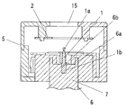
以下、本発明を添付図面に示す実施形態に基づいて説明する。図1、図2には、本発明の実施形態における一例の静電霧化装置を示している。   Hereinafter, the present invention will be described based on embodiments shown in the accompanying drawings. 1 and 2 show an example of an electrostatic atomizer according to an embodiment of the present invention.

本例の静電霧化装置は、霧化電極1と、霧化電極1と対向して位置する対向電極2と、霧化電極1に供給するための水を該霧化電極1に直接結露させる冷却手段3と、霧化電極1と対向電極2との間に高電圧を印加する高電圧印加部(図示せず)と、静電霧化を行うための制御部(図示せず)と、これらを保持する霧化部ハウジング5とを具備する。そして、高電圧印加部により対向電極2との間で霧化電極1に高電圧を印加することで、霧化電極1に結露して保持される水を霧化させ、ナノメータサイズを含む粒径であり且つ高い電荷を持つ帯電微粒子水を生成するものである。以下、更に詳細に説明する。   The electrostatic atomizer of this example directly condenses the atomizing electrode 1, the counter electrode 2 positioned opposite to the atomizing electrode 1, and water to be supplied to the atomizing electrode 1. A cooling means 3 to be applied, a high voltage application unit (not shown) for applying a high voltage between the atomizing electrode 1 and the counter electrode 2, and a control unit (not shown) for performing electrostatic atomization. And an atomizing section housing 5 for holding them. Then, by applying a high voltage to the atomizing electrode 1 between the counter electrode 2 by the high voltage application unit, the water retained by condensation on the atomizing electrode 1 is atomized, and the particle size includes a nanometer size. And generating charged fine particle water having a high charge. This will be described in more detail below.

対向電極2はドーナツ状をした金属板により構成しており、霧化部ハウジング5の図中上方を向く前面に設けた放出用開口15と対向するように、霧化部ハウジング5の内部空間の前部寄りに内装している。霧化部ハウジング5の内部空間の後部には霧化電極1を取付けており、霧化電極1の先端部1aが、ドーナツ状をした対向電極2の中央孔部のセンターと同一軸線上に位置するように設けている。この霧化電極1と対向電極2とは、高圧リード線(図示せず)を介して高電圧印加部に電気的に接続する。   The counter electrode 2 is formed of a doughnut-shaped metal plate, and the inner space of the atomizing portion housing 5 is opposed to the discharge opening 15 provided on the front surface of the atomizing portion housing 5 facing upward in the figure. The interior is closer to the front. The atomizing electrode 1 is attached to the rear part of the inner space of the atomizing part housing 5, and the tip part 1a of the atomizing electrode 1 is located on the same axis as the center of the central hole part of the counter electrode 2 having a donut shape. It is provided to do. The atomizing electrode 1 and the counter electrode 2 are electrically connected to a high voltage application unit via a high-voltage lead wire (not shown).

上記霧化電極1の基端部1bには、金属のような熱伝導性の良い熱伝導部材6が接続させてある。霧化電極1と熱伝導部材6は一体に形成したものでもよいし、霧化電極1に別体の熱伝導部材6を固着したものでもよいし、或いは、霧化電極1に別体の熱伝導部材6を接触させたものでもよい。いずれの場合も、熱伝導部材6と霧化電極1とで熱を高効率でやりとり可能な構成とする。   A heat conduction member 6 having good heat conductivity such as metal is connected to the base end portion 1 b of the atomizing electrode 1. The atomizing electrode 1 and the heat conducting member 6 may be formed integrally, or may be a member in which a separate heat conducting member 6 is fixed to the atomizing electrode 1, or a separate heat from the atomizing electrode 1. The conductive member 6 may be contacted. In either case, the heat conducting member 6 and the atomizing electrode 1 are configured to exchange heat with high efficiency.

図1、図2に示す実施形態では、柱状をした金属製の熱伝導部材6の前面部に凹所6aを形成するとともに、該凹所6aの底に嵌め込み穴6bを形成している。この嵌め込み穴6bに、棒状をした霧化電極1の基端部1bを嵌め込むことにより、嵌め込み穴6bの内面と霧化電極1の基端部1bとが接触して効果的に熱伝導されるようになっている。霧化部ハウジング5の後面には孔部7が設けてあり、熱伝導部材6の後部はこの孔部7を挿通して後方に延出されている。なお、霧化部ハウジング5の孔部7には、熱伝導部材6を囲むようにヒータが収納してある。   In the embodiment shown in FIGS. 1 and 2, a recess 6a is formed in the front surface portion of a columnar metal heat conduction member 6, and a fitting hole 6b is formed in the bottom of the recess 6a. By fitting the base end 1b of the atomizing electrode 1 in the form of a rod into the fitting hole 6b, the inner surface of the fitting hole 6b and the base end 1b of the atomizing electrode 1 are brought into contact with each other for effective heat conduction. It has become so. A hole 7 is provided on the rear surface of the atomizing unit housing 5, and the rear part of the heat conducting member 6 extends rearward through the hole 7. Note that a heater is accommodated in the hole portion 7 of the atomizing portion housing 5 so as to surround the heat conducting member 6.

この柱状の熱伝導部材6の後端部は、放熱部9と冷却部10の間で冷媒を循環させる冷凍サイクルFの該冷却部10に当接させており、熱伝導部材6と冷却部10とを熱的に接続させている。つまり、本例において霧化電極1は熱伝導部材6を介して冷却部10により冷却される構造になっており、この冷却部10及び熱伝導部材6により、霧化電極1を冷却して結露水を生成する冷却手段3を形成している。   The rear end of the columnar heat conducting member 6 is in contact with the cooling unit 10 of the refrigeration cycle F that circulates the refrigerant between the heat radiating unit 9 and the cooling unit 10. And are thermally connected. That is, in this example, the atomizing electrode 1 is structured to be cooled by the cooling unit 10 via the heat conducting member 6, and the atomizing electrode 1 is cooled and condensed by the cooling unit 10 and the heat conducting member 6. A cooling means 3 for generating water is formed.

上記冷凍サイクルFは、冷媒を循環させる冷媒回路中に、冷媒ガスを高温高圧に圧縮する圧縮器11と、高温高圧となった冷媒ガスを冷却して(放熱させて)冷媒液とする熱交換器から成る凝縮器12と、冷媒液を乾燥させるドライヤ16と、冷媒液を減圧して気化しやすくする膨張弁13と、減圧された冷媒液を気化させて冷媒ガスに戻す熱交換器から成る蒸発器14とをこの順に介在させ、冷媒を循環させながら圧縮器11及び凝縮器12で放熱を行い、膨張弁13及び蒸発器14で吸熱を行うものである。   The refrigeration cycle F includes a compressor 11 that compresses a refrigerant gas to a high temperature and a high pressure in a refrigerant circuit that circulates the refrigerant, and heat exchange that cools (dissipates heat) the refrigerant gas that has become a high temperature and a high pressure to obtain a refrigerant liquid. A condenser 12 composed of a condenser, a dryer 16 that dries the refrigerant liquid, an expansion valve 13 that depressurizes the refrigerant liquid to facilitate vaporization, and a heat exchanger that vaporizes the depressurized refrigerant liquid and returns it to the refrigerant gas. The evaporator 14 is interposed in this order, heat is radiated by the compressor 11 and the condenser 12 while circulating the refrigerant, and heat is absorbed by the expansion valve 13 and the evaporator 14.

つまり、ここでの圧縮器11や凝縮器12が放熱部9を形成し、膨張弁13や蒸発器14が冷却部10を形成している。熱伝導部材6の後端部は、上記冷却部10を成す蒸発器14に当接させている。   That is, the compressor 11 and the condenser 12 here form the heat radiating part 9, and the expansion valve 13 and the evaporator 14 form the cooling part 10. The rear end portion of the heat conducting member 6 is in contact with the evaporator 14 constituting the cooling unit 10.

上記構成の静電霧化装置において、冷凍サイクルF中の冷媒を循環させると、蒸発器14が冷却側となって冷えることで、熱伝導部材6を介した熱のやり取りによって霧化電極1の温度が低下する。霧化電極1の温度が低下すると、霧化部ハウジング5内の空気が冷やされ、該空気中に含まれる水分を基に霧化電極1に結露水が生成される。このようにして、霧化電極1には安定して水が供給される。   In the electrostatic atomizer having the above-described configuration, when the refrigerant in the refrigeration cycle F is circulated, the evaporator 14 cools down on the cooling side, so that the atomization electrode 1 of the atomization electrode 1 is exchanged by heat exchange through the heat conducting member 6. The temperature drops. When the temperature of the atomizing electrode 1 decreases, the air in the atomizing unit housing 5 is cooled, and condensed water is generated on the atomizing electrode 1 based on the moisture contained in the air. In this way, water is stably supplied to the atomizing electrode 1.

なお、冷却手段3により結露水を生成して霧化電極1に供給するための構成としては、図示例のように霧化電極1を冷却して該霧化電極1に直接結露を生じさせる構成に限定されない。つまり、例えば冷却手段3に熱的に接続されて冷却される冷却面を別途備え、該冷却面上で生成された結露水を霧化電極1に搬送する構成であっても構わない。   In addition, as a structure for producing | generating dew condensation water by the cooling means 3 and supplying it to the atomization electrode 1, the structure which cools the atomization electrode 1 like the example of illustration, and produces the dew condensation directly to this atomization electrode 1 It is not limited to. In other words, for example, a cooling surface that is thermally connected to the cooling means 3 and is cooled may be separately provided, and the condensed water generated on the cooling surface may be conveyed to the atomizing electrode 1.

このように霧化電極1に水が安定供給される状態で、高電圧印加部により霧化電極1と対向電極2との間に高電圧を印加すると、霧化電極1と対向電極2との間にかけられた高電圧により霧化電極1の先端部1aに供給された水と対向電極2との間にクーロン力が働き、水の液面が局所的に錐状に盛り上がっていわゆるテイラーコーンが形成される。このようにしてテイラーコーンが形成されると、該テイラーコーンの先端に電荷が集中してこの部分の電界強度が大きくなり、この部分に生じるクーロン力が大きくなることで更にテイラーコーンを成長させる。テイラーコーンが成長し、該テイラーコーンの先端に電荷が集中して電荷の密度が高密度となると、テイラーコーンの先端部分の水が大きなエネルギー(高密度となった電荷の反発力)を受け、表面張力を超えて分裂・飛散を繰り返すいわゆるレイリー分裂を生じて、ナノメータサイズの粒径を含む帯電微粒子水を大量に生成する。   When a high voltage is applied between the atomizing electrode 1 and the counter electrode 2 by the high voltage application unit in a state where water is stably supplied to the atomizing electrode 1 in this manner, A coulomb force acts between the water supplied to the tip 1a of the atomizing electrode 1 and the counter electrode 2 due to the high voltage applied therebetween, so that the level of the water locally rises in a conical shape and a so-called Taylor cone is formed. It is formed. When the Taylor cone is formed in this way, the electric charge concentrates at the tip of the Taylor cone and the electric field strength in this portion increases, and the Coulomb force generated in this portion increases, thereby further growing the Taylor cone. When the Taylor cone grows and the charge concentrates at the tip of the Taylor cone and the density of the charge becomes high, the water at the tip of the Taylor cone receives a large energy (the repulsive force of the charge that has become dense), So-called Rayleigh splitting that repeats splitting and scattering beyond the surface tension occurs, and a large amount of charged fine particle water containing nanometer-sized particle diameter is generated.

このようにして生成された帯電微粒子水は、対向電極2の中央孔部を通過して霧化部ハウジング5前面の放出用開口15から、霧化部ハウジング5外部の対象空間向けて放出される。   The charged fine particle water thus generated passes through the central hole of the counter electrode 2 and is discharged from the discharge opening 15 on the front surface of the atomizing unit housing 5 toward the target space outside the atomizing unit housing 5. .

対象空間に放出された帯電微粒子水は、その粒径がナノメータサイズと極めて小さいために空気中に長時間浮遊するとともに拡散性が高いため、対象空間内の隅々まで浮遊して、対象空間の壁面や該対象空間内にある物に付着する。しかも、帯電微粒子水には活性種が水分子に包み込まれるようにして存在するため、脱臭効果、アレルゲン物質の不活性化、カビや菌の除菌や繁殖の抑制効果を有し、対象空間の壁や内部の物に付着して脱臭効果、アレルゲン物質の不活性化、カビや菌の除菌や繁殖の抑制効果を発揮する。ここで、帯電微粒子水は遊離基単独で存在する場合より寿命が長いため、上記拡散性、脱臭効果、アレルゲン物質の不活性化、カビや菌の除菌や繁殖の抑制効果をより高く発揮するものとなる。   The charged fine particle water released into the target space floats in the air for a long time and has high diffusivity because its particle size is as small as nanometers. It adheres to walls and objects in the target space. Moreover, since the active species are present in the charged fine particle water so as to be encapsulated in water molecules, it has a deodorizing effect, inactivation of allergen substances, sterilization of fungi and fungi, and suppression of breeding, and in the target space. It adheres to walls and internal objects and exhibits deodorizing effect, inactivation of allergens, sterilization of fungi and fungi, and suppression of growth. Here, since the charged fine particle water has a longer life than when the free radicals are present alone, the above-mentioned diffusibility, deodorizing effect, inactivation of allergen substances, fungi and fungi sterilization and propagation suppression effect are exhibited more highly. It will be a thing.

そして、上記構成の静電霧化装置においては、冷凍サイクルFの冷却部10を用いて結露水を生成し、この水を霧化電極1に安定供給する構成になっているので、水の補給の手間が不要となり、且つ、得られた水には不純物が含まれないことからCaCOやMgO等が析出付着することもない。また、冷凍サイクルFを用いて結露水を得ることで、例えばペルチェユニットを用いて結露水を得る場合よりも消費電力を抑制することができる。 And in the electrostatic atomizer of the said structure, since it has the structure which produces | generates condensed water using the cooling part 10 of the refrigerating cycle F, and supplies this water to the atomization electrode 1 stably, replenishment of water And the obtained water contains no impurities, so that CaCO 3 , MgO and the like are not deposited. Moreover, by obtaining dew condensation water using the refrigerating cycle F, power consumption can be suppressed rather than the case where dew condensation water is obtained using a Peltier unit, for example.

加えて、静電霧化装置を組み込んだ各種機器(後述の冷蔵庫、除湿機、空気調和機等)を提供する場合に、例えば冷却手段3としてペルチェユニットを用いる構造であれば、このペルチェユニットが専用の装置として必要になるとともに該ペルチェユニット専用の電力を別途供給する必要があり、機器全体のコンパクト化や低コスト化、省エネルギ化を阻害するのに対して、上記構成の静電霧化装置によれば、各種機器において本来的な機能を発揮するために備えてある冷凍サイクルFの一部を活用して結露水生成用の冷却手段3を形成することができる。そのため、冷却手段3として専用の装置を備えることなく、また専用の電力を別途供給する必要なく、機器にとって必須の冷凍サイクルFの設備及び冷却能力の一部を利用して結露水を生成することができるので、機器全体のコンパクト化や低コスト化、省エネルギ化が実現される。   In addition, when providing various devices (such as a refrigerator, a dehumidifier, an air conditioner, etc., which will be described later) incorporating an electrostatic atomizer, if the Peltier unit is a structure that uses a Peltier unit as the cooling means 3, for example, In addition to being necessary as a dedicated device, it is necessary to separately supply the power dedicated to the Peltier unit, which reduces the overall size of the device, reduces costs, and conserves energy. According to the apparatus, the cooling means 3 for generating condensed water can be formed by utilizing a part of the refrigeration cycle F that is provided in order to exhibit essential functions in various devices. Therefore, it is not necessary to provide a dedicated device as the cooling means 3, and it is not necessary to supply dedicated power separately, and the condensed water is generated using a part of the refrigeration cycle F equipment and cooling capacity essential for the equipment. Therefore, the entire device can be made compact, low cost, and energy saving.

以下に述べる他の実施形態においては、上記した一例の静電霧化装置を、本来必須の構成として冷凍サイクルFを備えて冷媒を循環させる機器(以下「冷媒循環機器」という。)に組み込んだ場合を示す。つまり、以下に述べる冷媒循環機器は、放熱部9と冷却部10との間で冷媒を循環させる冷凍サイクルFの該冷却部10を通じて空気を冷却する冷媒循環機器であって、霧化電極1と、霧化電極1に供給するための水を結露させる冷却手段3とを具備し、霧化電極1に高電圧を印加することで霧化電極1に保持される水を霧化させて帯電微粒子水を生成する静電霧化装置を組み込んで形成されるとともに、上記静電霧化装置の冷却手段3として、冷凍サイクルFの該冷却部10を用いたものである。   In other embodiments described below, the electrostatic atomizer of the above-described example is incorporated in an apparatus (hereinafter referred to as “refrigerant circulation apparatus”) that includes the refrigeration cycle F as an essential component and circulates the refrigerant. Show the case. That is, the refrigerant circulation device described below is a refrigerant circulation device that cools air through the cooling unit 10 of the refrigeration cycle F that circulates the refrigerant between the heat radiating unit 9 and the cooling unit 10. And a cooling means 3 for condensing water to be supplied to the atomizing electrode 1, and by applying a high voltage to the atomizing electrode 1, the water held in the atomizing electrode 1 is atomized to form charged fine particles. While forming the electrostatic atomizer which produces | generates water, this cooling part 10 of the refrigerating cycle F is used as the cooling means 3 of the said electrostatic atomizer.

図3には、冷媒循環機器である冷蔵庫に一例の静電霧化装置を組み込んだ場合を示している。図示のように冷蔵庫本体20内には、空間内に貯蔵される食品を冷やす貯蔵室である冷凍室21、冷蔵室22、野菜室23と、各室21,22,23に連通する冷気通路24を設けており、冷蔵庫本体20内にて冷凍室21、冷蔵室22、野菜室23、冷気通路24をそれぞれ仕切る隔壁部30は、断熱材により形成している。冷気通路24と冷凍室21、冷蔵室22、野菜室23とを仕切る隔壁部30にはそれぞれ冷気通路24と冷凍室21、冷気通路24と冷蔵室22、冷気通路24と野菜室23を連通する連通部27a、27b、27cが設けてある。   In FIG. 3, the case where the electrostatic atomizer of an example is integrated in the refrigerator which is a refrigerant | coolant circulation apparatus is shown. As shown in the figure, in the refrigerator main body 20, a freezer compartment 21, a refrigerator compartment 22, a vegetable compartment 23, which is a storage compartment for cooling food stored in the space, and a cold air passage 24 communicating with each of the rooms 21, 22, 23. In the refrigerator main body 20, the partition wall 30 that partitions the freezer compartment 21, the refrigerator compartment 22, the vegetable compartment 23, and the cold air passage 24 is formed of a heat insulating material. The cold air passage 24 and the freezer compartment 21, the cold air passage 24 and the refrigerator compartment 22, and the cold air passage 24 and the vegetable compartment 23 communicate with the partition wall 30 that partitions the cold air passage 24 from the freezer compartment 21, the refrigerator compartment 22, and the vegetable compartment 23, respectively. Communication portions 27a, 27b, and 27c are provided.

冷凍室21、冷蔵室22、野菜室23には引出しボックス26a、26b、26cが引き出し自在に取付けられるとともに各引出しボックス26a、26b、26cの前部に扉25a、25b、25cを一体に設けている。引き出しボックス26a、26b、26cを冷凍室21や冷蔵室22、野菜室23内に押し込んで収納すると、引出しボックス26a、26b、26cの前部に設けた扉25a、25b、25cが前開口を閉じる構造である。   Drawer boxes 26a, 26b, and 26c are removably attached to the freezer compartment 21, the refrigerator compartment 22, and the vegetable compartment 23, and doors 25a, 25b, and 25c are integrally provided in front portions of the drawer boxes 26a, 26b, and 26c. Yes. When the drawer boxes 26a, 26b, and 26c are pushed into and stored in the freezer compartment 21, the refrigerator compartment 22, and the vegetable compartment 23, the doors 25a, 25b, and 25c provided at the front portions of the drawer boxes 26a, 26b, and 26c close the front opening. Structure.

冷気通路24内には、冷凍サイクルFの蒸発器14から成る冷却部10や、冷気送風用のファン29を設けており、冷却部10によって冷気通路24内の空気を例えば−20℃程度に冷却し、この冷気通路24内の冷却空気を連通部27a、27b、27cを介して冷凍室21、冷蔵室22、野菜室23に供給してそれぞれを目的温度とするようになっている。ここで、冷蔵室22や野菜室23は冷凍室21よりも温度を高くするため、連通部27b、27cは連通部27aよりも小さい開口とし、冷気通路24からの冷却空気の流入量が冷凍室21に比べて少なくなるように設定している。また、図示は省略しているが、冷凍室21、冷蔵室22、野菜室23からそれぞれ冷気通路24の冷却部10側に空気を返送するための返送通路を設けている。   In the cold air passage 24, a cooling unit 10 including the evaporator 14 of the refrigeration cycle F and a fan 29 for blowing cold air are provided. The cooling unit 10 cools the air in the cold air passage 24 to, for example, about −20 ° C. The cooling air in the cold air passage 24 is supplied to the freezing room 21, the refrigerating room 22, and the vegetable room 23 through the communication portions 27a, 27b, and 27c so that each of them is set to a target temperature. Here, since the refrigerator compartment 22 and the vegetable compartment 23 have higher temperatures than the freezer compartment 21, the communication portions 27b and 27c have openings smaller than the communication portion 27a, and the inflow amount of cooling air from the cold air passage 24 is the freezer compartment. It is set to be smaller than 21. Although not shown, return passages are provided for returning air from the freezer compartment 21, the refrigerator compartment 22, and the vegetable compartment 23 to the cooling section 10 side of the cold air passage 24, respectively.

冷凍サイクルFのうち冷却部10を成す蒸発器14を除く部分は、冷蔵庫本体20の後部に形成してある収容空間B内に配している。この冷凍サイクルFの放熱部9が位置することになる収容空間Bは、断熱材から成る隔壁部31によって、冷却部10が位置することになる後述の冷却空間A2と仕切られている。収容空間B内には送風用のファン32が設けてあり、放熱部9が発する熱を冷蔵庫本体20の後面に設けてある通気口33を通じて外部に放出するようになっている。なお、冷凍サイクルFの膨張弁13やドライヤ16については図示を省略している。   A portion of the refrigeration cycle F excluding the evaporator 14 that constitutes the cooling unit 10 is disposed in a storage space B formed at the rear of the refrigerator main body 20. The accommodation space B in which the heat radiating part 9 of the refrigeration cycle F is located is partitioned from a later-described cooling space A2 in which the cooling part 10 is located by a partition part 31 made of a heat insulating material. A fan 32 for blowing air is provided in the housing space B, and heat generated by the heat radiating unit 9 is released to the outside through a vent 33 provided on the rear surface of the refrigerator body 20. The expansion valve 13 and the dryer 16 of the refrigeration cycle F are not shown.

上記構成の冷蔵庫においては、野菜室23等の貯蔵庫内の空間が結露空間A1となり、断熱材より成る隔壁部30を介して隣接する冷気通路24が、これら結露空間A1よりも温度が低い冷却空間A2となっている。なお、図示例では野菜室23のみを結露空間A1としている。ここで、本発明における冷却空間A2とは温度が0℃以下の領域のことであり、この冷蔵庫のように冷気通路24を冷却空間A2とした場合には、冷却空間A2は上記のように−20℃程度となる。   In the refrigerator having the above-described configuration, the space in the storage room such as the vegetable compartment 23 becomes the condensation space A1, and the adjacent cool air passage 24 via the partition wall portion 30 made of a heat insulating material has a lower temperature than the condensation space A1. It is A2. In the illustrated example, only the vegetable compartment 23 is set as the condensation space A1. Here, the cooling space A2 in the present invention is a region having a temperature of 0 ° C. or lower. When the cold air passage 24 is the cooling space A2 as in this refrigerator, the cooling space A2 is − It becomes about 20 ° C.

静電霧化装置の霧化部ハウジング5は、結露空間A1を成す野菜室23と冷却空間A2を成す冷気通路24とを仕切る隔壁部30の、結露空間A1側の面に取付けてある。霧化部ハウジング5から後方に突出する熱伝導部材6の後部は、隔壁部30に設けてある貫通孔30aに挿入されて冷却空間A2内に露出している。この熱伝導部材6の後端部は、放熱部9と冷却部10の間で冷媒を循環させる冷凍サイクルFの該冷却部10に当接させており、冷却空間A2内において熱伝導部材6と冷却部10とを熱的に接続させている。   The atomizing section housing 5 of the electrostatic atomizer is attached to the surface on the side of the condensation space A1 of the partition wall section 30 that partitions the vegetable chamber 23 forming the condensation space A1 and the cold air passage 24 forming the cooling space A2. The rear part of the heat conducting member 6 protruding rearward from the atomizing part housing 5 is inserted into a through hole 30a provided in the partition wall part 30 and exposed in the cooling space A2. The rear end portion of the heat conducting member 6 is in contact with the cooling unit 10 of the refrigeration cycle F that circulates the refrigerant between the heat radiating unit 9 and the cooling unit 10. The cooling unit 10 is thermally connected.

したがって、熱伝導部材6はその後部が冷却空間A2内で冷却部10により冷やされるため、隔壁部30を挟んで結露空間A1側に位置する霧化電極1が冷やされることになる。この場合、霧化電極1は必ず0℃以下に冷却され、霧化電極1の周囲の空気中の水分(すなわち0℃以上の温度である結露空間A1の空気中の水分)を凍結させて霧化電極1に付着させる。なお、熱伝導部材6と冷却部10とは当接していなくともよく、冷却部10によって冷やされる冷却空間A2を通じて熱伝導部材6の露出部分が冷やされる構造にしても構わない。   Therefore, since the rear part of the heat conducting member 6 is cooled by the cooling part 10 in the cooling space A2, the atomizing electrode 1 located on the dew space A1 side is cooled with the partition wall part 30 interposed therebetween. In this case, the atomizing electrode 1 is always cooled to 0 ° C. or less, and moisture in the air around the atomizing electrode 1 (that is, moisture in the air in the condensation space A1 having a temperature of 0 ° C. or more) is frozen to form a mist. It is made to adhere to the chemical electrode 1. The heat conducting member 6 and the cooling unit 10 may not be in contact with each other, and the exposed portion of the heat conducting member 6 may be cooled through the cooling space A2 cooled by the cooling unit 10.

また図示はしていないが、本例の静電霧化装置においては、霧化電極1又は熱伝導部材6に隣接してヒータを設けて融解手段を構成してある。ヒータの通電のタイミング、ヒータへの通電時間、霧化電極1と対向電極2との間への高電圧を印加するタイミング、高電圧の印加停止のタイミング等は、制御部により制御される。   Although not shown, in the electrostatic atomizer of this example, a heater is provided adjacent to the atomizing electrode 1 or the heat conducting member 6 to constitute melting means. The timing for energizing the heater, the energizing time for the heater, the timing for applying a high voltage between the atomizing electrode 1 and the counter electrode 2, the timing for stopping the application of the high voltage, and the like are controlled by the control unit.

具体的には、霧化電極1は冷却手段3により連続して冷却されているが、ヒータへの通電及び高電圧の印加を行わない凍結期間と、凍結期間後にヒータへの通電を行う(高電圧の印加は行わない)融解期間と、融解期間後に高電圧を印加する(ヒータへの通電は継続する)静電霧化期間とが順番に繰り返されるように制御部によりヒータの通電、高電圧の印加の制御を行う。   Specifically, although the atomizing electrode 1 is continuously cooled by the cooling means 3, the energization to the heater and the energization to the heater after the freezing period are performed. (The voltage is not applied.) The heater turns on the heater and turns on the high voltage so that the melting period and the electrostatic atomization period in which the high voltage is applied after the melting period (the heater continues to be energized) are sequentially repeated. Is controlled.

上記凍結期間においては、熱伝導部材6が冷却空間A2内で冷やされ、霧化電極1が0℃以下である所定の目的温度(つまり結露空間A1の空気中の水分が凍結して氷となる温度)にまで冷やされることで、結露空間A1の空気中の水分が凍結されて霧化電極1に氷となって付着する。凍結期間が終了すると溶融期間に移行し、ヒータに通電して凍結した氷を融解して水を生成する。融解期間が終了すると霧化期間に移行し、ヒータへの通電を継続したまま霧化電極1と対向電極2との間に高電圧を印加し、既述したようにナノメータサイズの帯電微粒子水を大量に生成する。霧化電極1の先端部1aに供給された水は次第に少なくなり、水がなくなるタイミングで、高電圧印加とヒータへの通電を停止して霧化期間を終了する。霧化期間が終了すると再び凍結期間に移行し、上記と同じ順序で凍結による氷の付着、融解による水の供給、静電霧化を繰り返す。   In the freezing period, the heat conducting member 6 is cooled in the cooling space A2, and the atomization electrode 1 is frozen at a predetermined target temperature (that is, the water in the air in the condensation space A1 freezes to become ice. The water in the condensation space A1 is frozen and attached to the atomizing electrode 1 as ice. When the freezing period ends, the process proceeds to the melting period, and the heater is energized to melt the frozen ice to generate water. When the melting period ends, the atomization period starts, and a high voltage is applied between the atomization electrode 1 and the counter electrode 2 while the heater is continuously energized. Generate in large quantities. The amount of water supplied to the tip 1a of the atomizing electrode 1 gradually decreases, and at the timing when the water runs out, the application of the high voltage and the energization to the heater are stopped and the atomization period ends. At the end of the atomization period, the process proceeds to the freezing period again, and the adhesion of ice by freezing, the supply of water by melting and electrostatic atomization are repeated in the same order as described above.

このようにして生成された帯電微粒子水は、対向電極2の中央孔部を通過して霧化部ハウジング5の前面に設けた放出用開口15から、結露空間A1を成す野菜室23内に放出される。野菜室23内に放出された帯電微粒子水は、粒径がナノメータサイズと極めて小さいために空気中に長時間浮遊するとともに拡散性が高いため、野菜室23内の隅々まで浮遊して、野菜室23の内面や該野菜室23内に収納した収納物に付着することになる。そして、この野菜室23の内面や収納物に付着した帯電微粒子水が脱臭効果、カビ、菌の除菌、繁殖抑制効果を発揮する。   The charged fine particle water thus generated passes through the central hole of the counter electrode 2 and is discharged from the discharge opening 15 provided in the front surface of the atomizing section housing 5 into the vegetable compartment 23 forming the condensation space A1. Is done. The charged fine particle water discharged into the vegetable compartment 23 floats in the air for a long time and has high diffusibility because the particle size is extremely small, such as a nanometer size. It adheres to the inner surface of the chamber 23 and the stored items stored in the vegetable chamber 23. And the charged fine particle water adhering to the inner surface of the vegetable compartment 23 or the stored items exhibits a deodorizing effect, fungi, sterilization of bacteria, and a reproduction suppression effect.

活性種が水分子に包み込まれるようにして存在する帯電微粒子水は遊離基単独で存在する場合よりも寿命が長いため、上記拡散性、脱臭効果、カビや菌の除菌や繁殖の抑制効果がより向上することになる。また、帯電微粒子水は保湿効果があるため、結露空間A1内に入れた収納物を保湿する効果がある。   The charged fine particle water that exists in such a way that the active species is encapsulated in water molecules has a longer life than the case where the free radicals exist alone, so that the above diffusibility, deodorizing effect, mold and fungus sterilization and propagation suppression effects are achieved. It will be improved. In addition, since the charged fine particle water has a moisturizing effect, it has an effect of moisturizing the stored items in the condensation space A1.

そして、この静電霧化装置を組み込んだ冷蔵庫にあっては、冷蔵庫本来の冷却機能を発揮するために冷蔵庫本体20内に備えてある冷凍サイクルFを用い、この冷凍サイクルFの冷却部10の冷却能力の一部を利用して結露水を生成することができる。つまり、霧化電極1に供給する結露水を生成するためにペルチェユニット等の専用の冷却装置を備えることなく、またペルチェユニット駆動用等の専用の電力を別途供給する必要なく、本来的に備えてある冷凍サイクルFの設備及び冷却能力の一部を利用して結露水を安定供給することができるので、このような静電霧化装置を組み込んだ冷蔵庫全体のコンパクト化や低コスト化、省エネルギ化を図ることができる。   And in the refrigerator incorporating this electrostatic atomizer, in order to demonstrate the original cooling function of a refrigerator, the refrigerating cycle F provided in the refrigerator main body 20 is used, and the cooling part 10 of this refrigerating cycle F is used. Condensed water can be generated using part of the cooling capacity. In other words, in order to generate the dew condensation water to be supplied to the atomizing electrode 1, it is inherently provided without a dedicated cooling device such as a Peltier unit, or without separately supplying a dedicated power for driving the Peltier unit. As a result, it is possible to stably supply condensed water by using a part of the refrigeration cycle F equipment and cooling capacity, so that the entire refrigerator incorporating such an electrostatic atomizer can be made compact and low in cost. Energy can be achieved.

また、霧化電極1が位置して結露水を生成することになる結露空間A1(図示例では野菜室23内の空間)と、冷凍サイクルFの冷却部10が位置して冷却空気を生成する冷却空間A2(図示例では冷気通路24)とを、断熱性の隔壁部30により仕切ってあることで、結露空間A1を冷却空間A2に比較して温度や絶対湿度の高い空間に保ち、結露空間A1側を霧化電極1に結露水を生じやすい状態に保つことが可能となっている。   Moreover, the condensation space A1 (the space in the vegetable compartment 23 in the illustrated example) where the atomizing electrode 1 is located and the condensed water is generated, and the cooling unit 10 of the refrigeration cycle F are located to generate the cooling air. The cooling space A2 (in the illustrated example, the cool air passage 24) is partitioned by the heat insulating partition wall 30, so that the condensation space A1 is maintained in a space having a higher temperature and absolute humidity than the cooling space A2, and the condensation space is maintained. It is possible to keep the A1 side in a state in which condensed water is likely to be generated in the atomizing electrode 1.

しかも、この冷蔵庫にあっては、静電霧化装置の霧化電極1や対向電極2を、冷却部10やファン29よりも下流側の貯蔵室内(野菜室23内)に配設してあるため、霧化電極1から生じた帯電微粒子水が蒸発器14から成る冷却部10やファン29に接触することがなく、帯電微粒子水を冷却空気に乗せて貯蔵室内に効率良く散布することができる。   Moreover, in this refrigerator, the atomizing electrode 1 and the counter electrode 2 of the electrostatic atomizer are disposed in the storage room (in the vegetable compartment 23) downstream of the cooling unit 10 and the fan 29. Therefore, the charged fine particle water generated from the atomizing electrode 1 does not come into contact with the cooling unit 10 including the evaporator 14 or the fan 29, and the charged fine particle water can be efficiently dispersed in the storage chamber on the cooling air. .

図4には、冷媒循環機器である冷蔵庫に一例の静電霧化装置を組み込んだ場合の変形例を示している。なお、この変形例において、図3の実施形態の構成と同様の構成については同一符号を付して詳しい説明を省略し、図3の実施形態とは相違する特徴的な構成についてのみ詳述する。   FIG. 4 shows a modification in which an electrostatic atomizer as an example is incorporated in a refrigerator that is a refrigerant circulation device. In this modification, the same components as those of the embodiment of FIG. 3 are denoted by the same reference numerals and detailed description thereof is omitted, and only the characteristic components different from those of the embodiment of FIG. .

この変形例にあっては、冷凍サイクルFの放熱部9により加熱された高温空気の一部を、結露空間A1である野菜室23内の霧化電極1近傍に送り込む送風路35を備えている。これにより結露空間A1内の特に霧化電極1近傍を、結露空間A1の他の部分よりも温度や絶対湿度の高い空間に保ち、霧化電極1に結露水を生じやすい状態に保つことが可能となる。なお、放熱部9により加熱された空気の大部分は、やはり通気口33を通じて外気に放出される。   In this modification, the air passage 35 is provided to send a part of the high-temperature air heated by the heat radiating section 9 of the refrigeration cycle F to the vicinity of the atomizing electrode 1 in the vegetable compartment 23 which is the condensation space A1. . As a result, the vicinity of the atomizing electrode 1 in the condensation space A1 can be kept in a space where the temperature and absolute humidity are higher than other portions of the condensation space A1, and it is possible to keep the atomization electrode 1 in a state where condensation water is easily generated. It becomes. Note that most of the air heated by the heat radiating unit 9 is also released to the outside air through the vent 33.

上記送風路35は、放熱部9が配される収容空間Bと結露空間A1を冷却空間A2は避けて連通接続させる高温バイパス36と、この高温バイパス36を通じて送り込まれた空気を、結露空間A1の内壁に沿って霧化部ハウジング5(つまり霧化電極1近傍)にまで導くガイド流路37とから成る。上記送風路35のガイド流路37は、野菜室23内において引出しボックス26cとは接触しない後端位置に設けており、送り込まれる高温空気が引出しボックス26aに直接当たることなく、霧化部ハウジング5の放出用開口15に供給されるように設けている。   The air flow path 35 includes a high-temperature bypass 36 that connects the housing space B in which the heat radiating unit 9 is disposed and the dew condensation space A1 in communication with each other while avoiding the cooling space A2, and the air fed through the high-temperature bypass 36 in the dew space A1. It comprises a guide flow path 37 that leads to the atomizing section housing 5 (that is, the vicinity of the atomizing electrode 1) along the inner wall. The guide passage 37 of the blower passage 35 is provided in the vegetable chamber 23 at a rear end position that does not come into contact with the drawer box 26c, so that the high-temperature air that is fed does not directly hit the drawer box 26a, and the atomizing unit housing 5 Are provided so as to be supplied to the discharge opening 15.

なお、送風路35を通じて結露空間A1内に送り込まれる高温空気の量は、結露空間A1内を冷却する冷蔵庫としての冷却能力に影響を与えないように、連通部27cを通じて結露空間A1内に送り込まれる冷却空気の量に比して十分に少量に設定している。送風路35から送り込まれた高温空気は、霧化部ハウジング5の放出用開口15を通じて霧化電極1近傍に供給された後に、連通部27cを通じて送り込まれた冷却空気と合流する。上記のように冷却空気に比して高温空気は少量なので、合流後は十分な冷却能力を保持した冷却空気として貯蔵室である野菜室23内全体に供給される。   Note that the amount of high-temperature air sent into the condensation space A1 through the air passage 35 is sent into the condensation space A1 through the communication portion 27c so as not to affect the cooling capacity of the refrigerator that cools the condensation space A1. The amount is set to be sufficiently small compared to the amount of cooling air. The high-temperature air sent from the blower passage 35 is supplied to the vicinity of the atomizing electrode 1 through the discharge opening 15 of the atomizing unit housing 5 and then merges with the cooling air sent through the communication unit 27c. As described above, since the amount of high-temperature air is small compared to the cooling air, after the merging, it is supplied to the whole vegetable room 23 as a storage room as cooling air having sufficient cooling capacity.

また、図示はしていないが、上記送風路35を通じて結露空間A1外部から高温空気を送り込むのではなく、冷凍サイクルFの放熱部9の少なくとも一部を結露空間A1側の霧化部ハウジング5に隣接して(つまり霧化電極1近傍に)位置させることや、放熱部9に熱伝導部材を接続させるとともに該熱伝導部の一部を結露空間A1側の霧化部ハウジング5に隣接して位置させることも好適である。この場合、結露空間A1内の特に霧化電極1近傍を放熱部9や熱伝導部材により直接的に暖めることができ、結露空間A1の他の部分よりも温度や絶対湿度の高い空間に保って、霧化電極1に結露水を生じやすい状態にすることが可能となる。この場合も、放熱部9により結露空間A1を暖める熱量は、結露空間A1内を冷却する冷蔵庫としての冷却能力に影響を与えない程度に設定する。   Although not shown, high temperature air is not sent from the outside of the condensation space A1 through the air passage 35, but at least a part of the heat radiation portion 9 of the refrigeration cycle F is transferred to the atomization portion housing 5 on the condensation space A1 side. Adjacent (that is, in the vicinity of the atomizing electrode 1), or connecting a heat conducting member to the heat dissipating part 9 and a part of the heat conducting part adjacent to the atomizing part housing 5 on the condensation space A1 side It is also preferred to position it. In this case, particularly the vicinity of the atomizing electrode 1 in the condensation space A1 can be directly warmed by the heat dissipating part 9 and the heat conducting member, and the temperature and absolute humidity are kept higher than other portions of the condensation space A1. Thus, it becomes possible to make the atomizing electrode 1 in a state in which condensed water is likely to be generated. Also in this case, the amount of heat that warms the condensation space A1 by the heat radiating unit 9 is set to such an extent that does not affect the cooling capacity of the refrigerator that cools the inside of the condensation space A1.

図5には、冷媒循環機器である除湿機に一例の静電霧化装置を組み込んだ場合を示している。図示のように、除湿装置には除湿流路40が設けてあり、該除湿流路40は一端部が吸込部41となり且つ他端部が吐出部42となっている。吐出部42にはルーバ43が設けてある。除湿流路40の途中には、除湿手段44と送風手段45とが設けてある。   FIG. 5 shows a case where an electrostatic atomizer is incorporated into a dehumidifier that is a refrigerant circulation device. As shown in the figure, the dehumidifying device is provided with a dehumidifying channel 40, and the dehumidifying channel 40 has a suction part 41 at one end and a discharge part 42 at the other end. The discharge part 42 is provided with a louver 43. In the middle of the dehumidifying flow path 40, a dehumidifying means 44 and a blowing means 45 are provided.

図示例では除湿流路40の途中に除湿室46を設けており、該除湿室46内に、冷凍サイクルFの放熱部9を成す圧縮器11、凝縮器12や、冷却部10を成す蒸発器14等を備えることで、上記除湿手段44を構成している。この除湿室46の底部には排水部47を設けている。除湿機内の下部には水溜めタンク48を設けており、上記除湿室46の底部に設けた排水部47から流下した水を溜めるようになっている。なお、冷凍サイクルFの膨張弁13やドライヤ16については図示を省略している。   In the illustrated example, a dehumidifying chamber 46 is provided in the middle of the dehumidifying flow path 40, and in the dehumidifying chamber 46, the compressor 11, the condenser 12 that forms the heat radiating unit 9 of the refrigeration cycle F, and the evaporator that forms the cooling unit 10. 14 and the like constitute the dehumidifying means 44. A drainage portion 47 is provided at the bottom of the dehumidifying chamber 46. A water reservoir tank 48 is provided in the lower part of the dehumidifier, and the water flowing down from the drainage part 47 provided at the bottom of the dehumidifying chamber 46 is stored. The expansion valve 13 and the dryer 16 of the refrigeration cycle F are not shown.

除湿流路40の除湿室46よりも下流側には、送風手段45であるファンを収納する送風手段収納室49を設けている。除湿室46と送風手段収納室49とは、除湿室46の下流側の下端部に設けた連通口50で連通しており、除湿室46で除湿された乾燥空気が連通口50を経て送風手段収納室49に流入するようになっている。   On the downstream side of the dehumidifying chamber 46 of the dehumidifying channel 40, a blower means storage chamber 49 for storing a fan as the blower means 45 is provided. The dehumidifying chamber 46 and the blower means storage chamber 49 communicate with each other through a communication port 50 provided at the lower end portion on the downstream side of the dehumidifying chamber 46, and the dry air dehumidified in the dehumidifying chamber 46 passes through the communication port 50 to blow air. It flows into the storage chamber 49.

上記除湿機は、送風手段45を運転することで、外部空間である除湿対象空間Cの空気が吸込部41から吸い込まれて除湿手段44により除湿され、乾燥空気となって吐出部42から除湿対象空間C内に返送されることで、除湿対象空間Cの除湿をする。   The dehumidifier operates the air blowing means 45 so that the air in the dehumidifying target space C, which is an external space, is sucked from the suction part 41 and dehumidified by the dehumidifying means 44 to become dry air from the discharge part 42. By returning to the space C, the dehumidifying target space C is dehumidified.

上記除湿手段44において、吸込部41から吸込まれた湿った空気は冷凍サイクルFの放熱部9で熱交換されて加温され、冷却部10で冷やされて空気中の水分が結露水となり除去されることで、乾燥空気となる。ここで除湿により発生した水は、排水部47から水溜めタンク48に流れて溜められる。   In the dehumidifying means 44, the humid air sucked from the suction part 41 is heat-exchanged and heated by the heat radiating part 9 of the refrigeration cycle F, and cooled by the cooling part 10 to remove moisture in the air as condensed water. It becomes dry air. Here, the water generated by dehumidification flows from the drainage part 47 to the water reservoir tank 48 and is stored.

上記構成の除湿機には、除湿手段44で除湿した後の乾燥空気に帯電微粒子水を放出するために、一例の静電霧化装置を組み込んである。上記静電霧化装置は、既述したように霧化電極1を内蔵する霧化部ハウジング5と、霧化部ハウジング5内の霧化電極1に熱的に接続した熱伝導部材6とを備えたものであり、除湿流路40の側壁を成す隔壁部30に霧化部ハウジング5を貫通させている。   The dehumidifier configured as described above incorporates an electrostatic atomizer as an example in order to discharge charged fine particle water into the dry air after being dehumidified by the dehumidifying means 44. As described above, the electrostatic atomizer includes the atomizing unit housing 5 containing the atomizing electrode 1 and the heat conduction member 6 thermally connected to the atomizing electrode 1 in the atomizing unit housing 5. The atomization part housing 5 is penetrated by the partition part 30 which comprises the side wall of the dehumidification flow path 40.

この隔壁部30を挟んで一方には除湿室46が形成され、この除湿室46の冷却部10周辺の空間が冷却空間A2となっている。隔壁部30を挟んで他方には、除湿流路40の除湿室46及び送風手段収納室49よりも下流側の部分が形成されており、この下流側の部分が結露空間A1となっている。そして、上記冷却空間A2内には、静電霧化装置の熱伝導部材6が露出して位置するとともに冷却部10を成す蒸発器14に当接している。また、上記結露空間A1内には、霧化部ハウジング5に保持された状態で霧化電極1や対向電極2が位置している。なお、熱伝導部材6と冷却部10とは当接していなくともよく、冷却部10によって冷やされる冷却空間A2を通じて熱伝導部材6の露出部分が冷やされる構造であってもよい。   A dehumidifying chamber 46 is formed on one side of the partition wall 30, and a space around the cooling unit 10 in the dehumidifying chamber 46 is a cooling space A2. On the other side of the partition wall 30, a portion on the downstream side of the dehumidifying chamber 46 and the blowing means storage chamber 49 of the dehumidifying channel 40 is formed, and this downstream portion is a condensation space A <b> 1. And in the said cooling space A2, the heat conductive member 6 of an electrostatic atomizer is exposed and located, and contact | abuts to the evaporator 14 which comprises the cooling part 10. FIG. Moreover, the atomization electrode 1 and the counter electrode 2 are located in the said condensation space A1 in the state hold | maintained at the atomization part housing 5. FIG. The heat conducting member 6 and the cooling unit 10 may not be in contact with each other, and the exposed portion of the heat conducting member 6 may be cooled through the cooling space A2 cooled by the cooling unit 10.

上記構成の除湿機を運転すると、冷却空間A2内において冷凍サイクルFの冷却部10である蒸発器14が冷えるので、熱伝導部材6を介した熱のやりとりにより、結露空間A1内の霧化電極1の温度が低下する。霧化電極1の温度が低下すると霧化部ハウジング5内の空気が冷やされ、空気中に含まれる水分が結露水として霧化電極1に生成される。このようにして霧化電極1には水が安定供給され、霧化電極1と対向電極2との間に高電圧を印加することで既述したようにナノメータサイズの帯電微粒子水を大量に生成する。   When the dehumidifier having the above configuration is operated, the evaporator 14 which is the cooling unit 10 of the refrigeration cycle F is cooled in the cooling space A2, so that the atomization electrode in the condensation space A1 is exchanged by heat exchange through the heat conducting member 6. The temperature of 1 decreases. When the temperature of the atomizing electrode 1 decreases, the air in the atomizing unit housing 5 is cooled, and moisture contained in the air is generated in the atomizing electrode 1 as condensed water. In this way, water is stably supplied to the atomizing electrode 1, and a large amount of charged fine particle water of nanometer size is generated as described above by applying a high voltage between the atomizing electrode 1 and the counter electrode 2. To do.

生成された帯電微粒子水は、対向電極2の中央孔部を通過して霧化部ハウジング5に設けた放出用開口15から、除湿流路40の除湿手段44及び送風手段45よりも下流側の部分(つまり結露空間A1)に放出される。除湿流路40内に放出された帯電微粒子水は、送風手段45により送り込まれる乾燥空気に乗り、吐出部42から除湿対象空間C内に放出される。   The generated charged fine particle water passes through the central hole portion of the counter electrode 2 and is disposed downstream of the dehumidifying means 44 and the air blowing means 45 of the dehumidifying channel 40 from the discharge opening 15 provided in the atomizing portion housing 5. It is discharged into the portion (that is, the condensation space A1). The charged fine particle water discharged into the dehumidifying channel 40 rides on the dry air sent by the blowing means 45 and is discharged from the discharge unit 42 into the dehumidifying target space C.

除湿対象空間C内に放出された帯電微粒子水は、粒径がナノメータサイズと極めて小さいために空気中に長時間浮遊するとともに拡散性が高いため、除湿対象空間C内の隅々まで浮遊して、除湿対象空間Cの内面や該除湿対象空間C内に収納した収納物や人体に付着する。そして、この除湿対象空間Cの内面や収納物等に付着した帯電微粒子水が脱臭効果、カビ、菌の除菌、繁殖抑制効果を発揮する。   The charged fine particle water released into the dehumidification target space C floats in the air for a long time and has a high diffusibility because the particle size is as small as a nanometer size. It adheres to the inner surface of the dehumidification target space C, the stored items stored in the dehumidification target space C, and the human body. And the charged fine particle water adhering to the inner surface of the dehumidification target space C, the stored items, etc. exerts a deodorizing effect, fungi, sterilization of bacteria, and a reproduction suppression effect.

活性種が水分子に包み込まれるようにして存在する帯電微粒子水は遊離基単独で存在する場合よりも寿命が長いため、上記拡散性、脱臭効果、カビや菌の除菌や繁殖の抑制効果がより向上することになる。また、帯電微粒子水は保湿効果があるため、除湿対象空間C内の収納物や人体の肌を保湿する効果がある。   The charged fine particle water that exists in such a way that the active species is encapsulated in water molecules has a longer life than the case where the free radicals exist alone, so that the above diffusibility, deodorizing effect, mold and fungus sterilization and propagation suppression effects are achieved. It will be improved. Further, since the charged fine particle water has a moisturizing effect, it has the effect of moisturizing the contents stored in the dehumidifying target space C and the skin of the human body.

そして、この静電霧化装置を組み込んだ除湿機にあっては、除湿機本来の冷却機能を発揮するために除湿室46に内蔵してある冷凍サイクルFを用い、この冷凍サイクルFの冷却部10の冷却能力の一部を利用して結露水を生成することができる。つまり、霧化電極1に供給する結露水を生成するためにペルチェユニット等の専用の冷却装置を備えることなく、またペルチェユニット駆動用等の専用の電力を別途供給する必要なく、本来的に備えてある冷凍サイクルFの設備及び冷却能力の一部を利用して結露水を安定供給することができるので、このような静電霧化装置を組み込んだ除湿機全体のコンパクト化や低コスト化、省エネルギ化を図ることができる。   And in the dehumidifier incorporating this electrostatic atomizer, in order to exhibit the original cooling function of the dehumidifier, the refrigerating cycle F built in the dehumidifying chamber 46 is used, and the cooling part of this refrigerating cycle F Condensed water can be generated using a part of the 10 cooling capacities. In other words, in order to generate the dew condensation water to be supplied to the atomizing electrode 1, it is inherently provided without a dedicated cooling device such as a Peltier unit, or without separately supplying a dedicated power for driving the Peltier unit. Since the dew condensation water can be stably supplied using a part of the refrigeration cycle F equipment and cooling capacity, the entire dehumidifier incorporating such an electrostatic atomizer can be reduced in size and cost. Energy saving can be achieved.

また、霧化電極1が位置して結露水を生成することになる結露空間A1(図示例では除湿流路40の除湿手段44及び送風手段45よりも下流側の部分)と、冷凍サイクルFの冷却部10が位置して冷却空気を生成する冷却空間A2(図示例では除湿室46の冷却部10周辺の空間)とを、断熱性の隔壁部30により仕切ってあることで、結露空間A1を冷却空間A2に比較して温度や絶対湿度の高い空間に保ち、結露空間A1側を霧化電極1に結露水を生じやすい状態に保つことが可能となっている。   Further, the dew condensation space A1 (in the illustrated example, the portion on the downstream side of the dehumidifying means 44 and the air blowing means 45 in the illustrated example) where the atomizing electrode 1 is located to generate condensed water, and the refrigeration cycle F The condensation space A1 is formed by partitioning the cooling space A2 (the space around the cooling portion 10 in the dehumidifying chamber 46 in the illustrated example) by the heat insulating partition wall 30 where the cooling portion 10 is located and generates cooling air. It is possible to keep the temperature and absolute humidity higher than the cooling space A2, and to keep the condensation space A1 side in a state where condensation water is easily generated in the atomizing electrode 1.

しかも、この除湿機にあっては、静電霧化装置の霧化電極1や対向電極2を、除湿手段44や送風手段45よりも下流側に配設してあるため、除湿流路40内を流れる帯電微粒子水が放熱部9や冷却部10から成る除湿手段44やファンから成る送風手段45に接触することがなく、帯電微粒子水を乾燥空気に乗せて除湿対象空間C内に効率良く散布することができる。   In addition, in this dehumidifier, the atomizing electrode 1 and the counter electrode 2 of the electrostatic atomizer are disposed on the downstream side of the dehumidifying means 44 and the air blowing means 45. The charged fine particle water flowing through the air does not come into contact with the dehumidifying means 44 including the heat dissipating unit 9 and the cooling unit 10 and the blowing means 45 including the fan, and the charged fine particle water is efficiently dispersed in the dehumidifying target space C by being placed on the dry air. can do.

図6には、冷媒循環機器である除湿機に一例の静電霧化装置を組み込んだ場合の変形例を示している。なお、この変形例において、図5の実施形態の構成と同様の構成については同一符号を付して詳しい説明を省略し、図5の実施形態とは相違する特徴的な構成についてのみ詳述する。   FIG. 6 shows a modification in which an electrostatic atomizer as an example is incorporated in a dehumidifier that is a refrigerant circulation device. In this modification, the same components as those of the embodiment of FIG. 5 are denoted by the same reference numerals and detailed description thereof is omitted, and only the characteristic configurations different from those of the embodiment of FIG. .

この変形例にあっては、除湿室46内の冷凍サイクルFの放熱部9によって加熱された高温空気の一部を、結露空間A1(つまり、除湿流路40の除湿手段44及び送風手段45よりも下流側の部分)内の霧化電極1近傍に送り込む送風路35を備えている。これにより結露空間A1内の特に霧化電極1近傍を、結露空間A1の他の部分よりも温度や絶対湿度の高い空間に保ち、霧化電極1に結露水を生じやすい状態に保つことが可能となる。除湿室46内には、放熱部9周辺の高温空気の一部を除湿流路40から分岐させて送風路35に送り込む送風用のファン55を備えている。   In this modification, a part of the high-temperature air heated by the heat radiating part 9 of the refrigeration cycle F in the dehumidifying chamber 46 is transferred from the dew space A1 (that is, the dehumidifying means 44 and the blowing means 45 of the dehumidifying passage 40). Also provided is a blower passage 35 for feeding in the vicinity of the atomizing electrode 1 in the downstream portion). As a result, the vicinity of the atomizing electrode 1 in the condensation space A1 can be kept in a space where the temperature and absolute humidity are higher than other portions of the condensation space A1, and it is possible to keep the atomization electrode 1 in a state where condensation water is easily generated. It becomes. Inside the dehumidifying chamber 46 is provided with a fan 55 for blowing air that branches a part of the high-temperature air around the heat radiating section 9 from the dehumidifying channel 40 and sends it to the blowing channel 35.

上記送風路35は、除湿室46の放熱部9周辺の空間と結露空間A1を、除湿室46の放熱部9よりも下流側に位置する冷却部10周辺の冷却空間A2を避けて連通接続させる高温バイパス56と、この高温バイパス56を通じて送り込まれた空気を、結露空間A1の内壁を成す隔壁部30に沿って霧化部ハウジング5(つまり霧化電極1近傍)にまで導くガイド流路57とから成る。上記ガイド流路57は、高温バイパス56を通じて送り込まれた高温空気を隔壁部30に沿って吐出部42側から霧化部ハウジング5に向けて(つまり除湿流路40の下流側から上流側へと)送り込むように設けている。   The air passage 35 connects the space around the heat radiating portion 9 of the dehumidifying chamber 46 and the dew condensation space A1 while avoiding the cooling space A2 around the cooling portion 10 located downstream of the heat radiating portion 9 of the dehumidifying chamber 46. A high-temperature bypass 56 and a guide channel 57 that guides the air fed through the high-temperature bypass 56 to the atomizing unit housing 5 (that is, in the vicinity of the atomizing electrode 1) along the partition wall 30 that forms the inner wall of the condensation space A1. Consists of. The guide channel 57 moves the high-temperature air fed through the high-temperature bypass 56 from the discharge unit 42 side toward the atomization unit housing 5 along the partition wall 30 (that is, from the downstream side to the upstream side of the dehumidification channel 40). ) Provided to send in.

また、図示はしていないが、上記送風路35を通じて結露空間A1外部から高温空気を送り込むのではなく、冷凍サイクルFの放熱部9の少なくとも一部を、結露空間A1側の霧化部ハウジング5に隣接して(つまり霧化電極1近傍に)位置させることや、放熱部9に熱伝導部材を接続させるとともに該熱伝導部の一部を結露空間A1側の霧化部ハウジング5に隣接して位置させることも好適である。この場合、結露空間A1内の特に霧化電極1近傍を放熱部9や熱伝導部材により直接的に暖めることができ、結露空間A1の他の部分よりも温度や絶対湿度の高い空間に保って、霧化電極1に結露水を生じやすい状態にすることが可能となる。   Although not shown, high temperature air is not sent from the outside of the dew condensation space A1 through the air passage 35, but at least a part of the heat radiating unit 9 of the refrigeration cycle F is transferred to the atomization unit housing 5 on the dew space A1 side. Adjacent to the atomizing electrode 1 (that is, in the vicinity of the atomizing electrode 1), a heat conducting member is connected to the heat dissipating part 9, and a part of the heat conducting part is adjacent to the atomizing part housing 5 on the condensation space A1 side. It is also preferable to position them. In this case, particularly the vicinity of the atomizing electrode 1 in the condensation space A1 can be directly warmed by the heat dissipating part 9 and the heat conducting member, and the temperature and absolute humidity are kept higher than other portions of the condensation space A1. Thus, it becomes possible to make the atomizing electrode 1 in a state in which condensed water is likely to be generated.

図7には、冷媒循環機器である空気調和機に一例の静電霧化装置を組み込んだ場合を示している。この空気調和機は屋内機60と屋外機61から成り、屋内機60の外殻を成す左右方向に長い筐体62の後面部63を、空調対象空間Dである部屋の壁面に沿わせて設置している。筐体62の上面部64と前面部65の上側部分には、複数の吸込口66を設けている。また、筐体62の前面部65の下側部分には、左右方向に長い吹出口67を設けている。   In FIG. 7, the case where the electrostatic atomizer of an example is integrated in the air conditioner which is a refrigerant | coolant circulation apparatus is shown. This air conditioner is composed of an indoor unit 60 and an outdoor unit 61, and a rear surface portion 63 of a casing 62, which forms the outer shell of the indoor unit 60 and which is long in the left-right direction, is installed along the wall surface of the room that is the air-conditioning target space D. is doing. A plurality of suction ports 66 are provided in the upper surface portion 64 and the upper portion of the front surface portion 65 of the housing 62. In addition, a blower outlet 67 that is long in the left-right direction is provided in the lower portion of the front surface portion 65 of the housing 62.

上記筐体62には、吸込口66と吹出口67を連通させる送風経路69を形成している。送風経路69の途中には、空調対象空間Dである室内の空気を吸込口66から吸い込んで吹出口67から戻すためのファンから成る送風手段70を設けている。送風経路69の上流側端部にはフィルタ(図示せず)を配設しており、このフィルタよりも下流側で且つ送風手段70よりも上流側の部分には、冷凍サイクルFの一部を成す屋内側熱交換器72を配している。   The casing 62 is formed with an air passage 69 that allows the suction port 66 and the air outlet 67 to communicate with each other. In the middle of the air flow path 69, air blowing means 70 is provided that includes a fan for sucking indoor air, which is the air-conditioning target space D, from the air inlet 66 and returning it from the air outlet 67. A filter (not shown) is disposed at the upstream end portion of the air blowing path 69, and a part of the refrigeration cycle F is provided in a portion downstream of the filter and upstream of the air blowing means 70. An indoor side heat exchanger 72 is arranged.

ここでの冷凍サイクルFは、屋内機60内のアルミニウム製フィンから成る屋内側熱交換器72と、屋外機61内のアルミニウム製フィンから成る屋外側熱交換器73と、圧縮器11との間で冷媒を循環させる冷媒回路を成すものであり、冷媒を所定方向に循環させることで屋内側熱交換器72が蒸発器14(つまり冷却部10)となって冷却を行い、屋外側熱交換器73が凝縮器12(つまり放熱部9)となって放熱を行うように設定している。   Here, the refrigeration cycle F includes an indoor side heat exchanger 72 made of aluminum fins in the indoor unit 60, an outdoor side heat exchanger 73 made of aluminum fins in the outdoor unit 61, and the compressor 11. The refrigerant circuit is configured to circulate the refrigerant, and the refrigerant is circulated in a predetermined direction so that the indoor heat exchanger 72 serves as the evaporator 14 (that is, the cooling unit 10) for cooling, and the outdoor heat exchanger. 73 is set as the condenser 12 (that is, the heat radiating portion 9) so as to radiate heat.

したがって、空調対象空間D内の空気は、吸込口66を通じて送風経路69内に流入した後に、冷凍サイクルFの冷却部10を成す屋内側熱交換器72を通過して冷却され、冷却空気となったうえで送風経路69の下流側及び吹出口67を通じて空調対象空間D内に戻される。屋外機61内の放熱部9を成す屋外側熱交換器73により加熱された空気は、内蔵してあるファン71の送風に乗って通気口75を通じて屋外に放出される。なお、冷凍サイクルFの膨張弁13やドライヤ16については図示を省略している。   Therefore, after the air in the air-conditioning target space D flows into the ventilation path 69 through the suction port 66, the air passes through the indoor heat exchanger 72 that forms the cooling unit 10 of the refrigeration cycle F and is cooled to become cooling air. In addition, the air is returned to the air-conditioning target space D through the air flow path 69 on the downstream side and the air outlet 67. The air heated by the outdoor side heat exchanger 73 forming the heat radiating unit 9 in the outdoor unit 61 is discharged to the outside through the vent 75 by riding on the air blown by the built-in fan 71. The expansion valve 13 and the dryer 16 of the refrigeration cycle F are not shown.

また、筐体62内には、屋内側熱交換器72の表面で結露して生じた水を受けるためのドレインパン74を、屋内側熱交換器72及び送風手段70の下方に配置している。ドレインパン74には、一端が筐体62外部に連通する排水ホース(図示せず)の他端を連通接続しており、該排水ホースによりドレインパン74に溜まった結露水を屋外に排出できるようになっている。   In addition, a drain pan 74 for receiving water generated by condensation on the surface of the indoor heat exchanger 72 is disposed in the casing 62 below the indoor heat exchanger 72 and the air blowing means 70. . The drain pan 74 is connected to the other end of a drain hose (not shown) whose one end communicates with the outside of the housing 62, so that the condensed water accumulated in the drain pan 74 can be discharged to the outside by the drain hose. It has become.

上記構成の空気調和機には、冷却部10を通じて冷却した後の空気に帯電微粒子水を放出するために、一例の静電霧化装置を組み込んである。上記静電霧化装置は、既述したように霧化電極1を内蔵する霧化部ハウジング5と、霧化部ハウジング5内の霧化電極1に熱的に接続した熱伝導部材6とを備えたものであり、ドレインパン74の底壁に熱伝導部材6を貫通させている。   In the air conditioner having the above-described configuration, an electrostatic atomizer as an example is incorporated in order to discharge charged fine particle water to the air cooled through the cooling unit 10. As described above, the electrostatic atomizer includes the atomizing unit housing 5 containing the atomizing electrode 1 and the heat conduction member 6 thermally connected to the atomizing electrode 1 in the atomizing unit housing 5. The heat conducting member 6 is passed through the bottom wall of the drain pan 74.

つまりこの空気調和機の例では、ドレインパン74が断熱性の隔壁部30を成し、該隔壁部30挟んで上方には冷凍サイクルFの冷却部10が位置する冷却空間A2が形成されている。また、隔壁部30を挟んで下方には、送風経路69の冷却部10及び送風手段70よりも下流側の部分が形成されており、この下流側の部分が結露空間A1となっている。そして、上記冷却空間A2内には、静電霧化装置の熱伝導部材6が露出して位置するとともに冷却部10と当接している。なお、熱伝導部材6と冷却部10とは当接していなくともよく、冷却部10によって冷やされる冷却空間A2を通じて熱伝導部材6の露出部分が冷やされる構造であってもよい。また、上記結露空間A1内には、霧化部ハウジング5に保持された状態で霧化電極1や対向電極2が位置している。   That is, in this example of the air conditioner, the drain pan 74 forms the heat insulating partition wall 30, and the cooling space A <b> 2 in which the cooling unit 10 of the refrigeration cycle F is located is formed above the partition wall 30. . In addition, a portion downstream of the cooling portion 10 and the air blowing means 70 of the air passage 69 is formed below the partition wall portion 30, and this downstream portion is a condensation space A <b> 1. And in the said cooling space A2, the heat conductive member 6 of an electrostatic atomizer is exposed and located, and is contact | abutting with the cooling part 10. FIG. The heat conducting member 6 and the cooling unit 10 may not be in contact with each other, and the exposed portion of the heat conducting member 6 may be cooled through the cooling space A2 cooled by the cooling unit 10. Moreover, the atomization electrode 1 and the counter electrode 2 are located in the said condensation space A1 in the state hold | maintained at the atomization part housing 5. FIG.

隔壁部30を成すドレインパン74の後端と筐体62の後面部63との間には、ドレインパン74上方の冷却空間A2とドレインパン74下方の結露空間A1とを連通させる隙間77を形成している。これにより、送風経路69には上流側から順に吸込口66、フィルタ、冷却部10が位置する冷却空間A2、送風手段70、上記隙間77、霧化電極1等が位置する結露空間A1、吹出口67が配置され、冷却空間A2と結露空間A1とが隔壁部30を介して仕切られた構造になっている。   A gap 77 is formed between the rear end of the drain pan 74 forming the partition wall 30 and the rear surface portion 63 of the housing 62 so as to communicate the cooling space A2 above the drain pan 74 and the condensation space A1 below the drain pan 74. is doing. As a result, the suction path 66, the filter, the cooling space A2 where the cooling unit 10 is located, the air blowing means 70, the gap 77, the condensing space A1 where the atomizing electrode 1 and the like are located, and the air outlet are arranged in order from the upstream side. 67 is arranged, and the cooling space A2 and the dew condensation space A1 are partitioned through the partition wall 30.

上記構成の空気調和機を運転すると、冷却空間A2内において冷凍サイクルFの冷却部10となる屋内側熱交換器72が冷えるので、熱伝導部材6を介した熱のやりとりにより、結露空間A1内の霧化電極1の温度が低下する。霧化電極1の温度が低下すると霧化部ハウジング5内の空気が冷やされ、空気中に含まれる水分が結露水として霧化電極1に生成される。このようにして霧化電極1には水が安定供給され、霧化電極1と対向電極2との間に高電圧を印加することで既述したようにナノメータサイズの帯電微粒子水を大量に生成する。   When the air conditioner having the above configuration is operated, the indoor heat exchanger 72 serving as the cooling unit 10 of the refrigeration cycle F is cooled in the cooling space A2, so that heat exchange via the heat conducting member 6 causes the inside of the condensation space A1. The temperature of the atomizing electrode 1 decreases. When the temperature of the atomizing electrode 1 decreases, the air in the atomizing unit housing 5 is cooled, and moisture contained in the air is generated in the atomizing electrode 1 as condensed water. In this way, water is stably supplied to the atomizing electrode 1, and a large amount of charged fine particle water of nanometer size is generated as described above by applying a high voltage between the atomizing electrode 1 and the counter electrode 2. To do.

生成された帯電微粒子水は、対向電極2の中央孔部を通過して霧化部ハウジング5に設けた放出用開口15から、送風経路69内の冷却空間A2や送風手段70よりも下流側の部分(つまり結露空間A1)に放出される。送風経路69内に放出された帯電微粒子水は、送風手段70により込まれる冷却空気に乗り、吹出口67から空調対象空間D内に放出される。   The generated charged fine particle water passes through the central hole portion of the counter electrode 2 and from the discharge opening 15 provided in the atomizing portion housing 5, on the downstream side of the cooling space A <b> 2 in the blowing path 69 and the blowing means 70. It is discharged into the portion (that is, the condensation space A1). The charged fine particle water discharged into the air blowing path 69 rides on the cooling air introduced by the air blowing means 70 and is discharged from the air outlet 67 into the air conditioning target space D.

空調対象空間D内に放出された帯電微粒子水は、粒径がナノメータサイズと極めて小さいために空気中に長時間浮遊するとともに拡散性が高いため、空調対象空間D内の隅々まで浮遊して、空調対象空間Dの内面や該空調対象空間D内に収納した収納物や人体に付着する。そして、この空調対象空間Dの内面や収納物等に付着した帯電微粒子水が脱臭効果、カビ、菌の除菌、繁殖抑制効果を発揮する。   The charged fine particle water discharged into the air-conditioning target space D floats in the air for a long time and has high diffusibility because the particle size is extremely small, such as a nanometer size. It adheres to the inner surface of the air-conditioning target space D, the stored items or the human body stored in the air-conditioning target space D. And the charged fine particle water adhering to the inner surface of the air-conditioning target space D, the stored items, etc. exerts a deodorizing effect, fungi, sterilization of bacteria, and a reproduction suppression effect.

活性種が水分子に包み込まれるようにして存在する帯電微粒子水は遊離基単独で存在する場合よりも寿命が長いため、上記拡散性、脱臭効果、カビや菌の除菌や繁殖の抑制効果がより向上することになる。また、帯電微粒子水は保湿効果があるため、空調対象空間D内の収納物や人体の肌を保湿する効果がある。   The charged fine particle water that exists in such a way that the active species is encapsulated in water molecules has a longer life than the case where the free radicals exist alone, so that the above diffusibility, deodorizing effect, mold and fungus sterilization and propagation suppression effects are achieved. It will be improved. Further, since the charged fine particle water has a moisturizing effect, it has an effect of moisturizing the contents in the air-conditioning target space D and the skin of the human body.

そして、この静電霧化装置を組み込んだ空気調和機にあっては、空気調和機本来の冷却機能を発揮するために屋内機60と屋外機61との間で形成している冷凍サイクルFを用い、この冷凍サイクルFのうち屋内機60側で働く冷却部10の冷却能力の一部を利用して結露水を生成することができる。つまり、霧化電極1に供給する結露水を生成するためにペルチェユニット等の専用の冷却装置を備えることなく、またペルチェユニット駆動用等の専用の電力を別途供給する必要なく、本来的に備えてある冷凍サイクルFの設備及び冷却能力の一部を利用して結露水を安定供給することができるので、このような静電霧化装置を組み込んだ空気調和機全体のコンパクト化や低コスト化、省エネルギ化を図ることができる。   And in the air conditioner incorporating this electrostatic atomizer, the refrigeration cycle F formed between the indoor unit 60 and the outdoor unit 61 in order to exhibit the original cooling function of the air conditioner is provided. The dew condensation water can be generated by utilizing a part of the cooling capacity of the cooling unit 10 that works on the indoor unit 60 side in the refrigeration cycle F. In other words, in order to generate the dew condensation water to be supplied to the atomizing electrode 1, it is inherently provided without a dedicated cooling device such as a Peltier unit, or without separately supplying a dedicated power for driving the Peltier unit. The dew condensation water can be stably supplied using a part of the existing refrigeration cycle F equipment and cooling capacity, so the whole air conditioner incorporating such an electrostatic atomizer can be made compact and low in cost. Energy saving can be achieved.

また、霧化電極1が位置して結露水を生成することになる結露空間A1(図示例では送風経路69内の冷却空間A2や送風手段70よりも下流側の部分)と、冷凍サイクルFの冷却部10が位置して冷却空気を生成する冷却空間A2(図示例では送風経路69内の冷却部10周辺の空間)とを、ドレインパン74から成る断熱性の隔壁部30により仕切ってあることで、結露空間A1を冷却空間A2に比較して温度や絶対湿度の高い空間に保ち、結露空間A1側を霧化電極1に結露水を生じやすい状態に保つことが可能となっている。   In addition, the condensation space A1 (where the atomization electrode 1 is located to generate condensed water (in the illustrated example, the portion on the downstream side of the cooling space A2 and the air blowing means 70 in the air blowing path 69) and the refrigeration cycle F The cooling space A2 in which the cooling section 10 is located and generates cooling air (in the illustrated example, the space around the cooling section 10 in the air blowing path 69) is partitioned by a heat insulating partition wall section 30 including a drain pan 74. Therefore, it is possible to keep the dew condensation space A1 in a space having a higher temperature and absolute humidity than the cooling space A2, and to keep the dew condensation space A1 side in a state in which dew condensation water tends to be generated.

しかも、この空気調和機にあっては、静電霧化装置の霧化電極1や対向電極2を、冷却部10や送風手段70よりも下流側に配設してあるため、送風経路69内を流れる帯電微粒子水がフィンから成る冷却部10やファンから成る送風手段70に接触することがなく、帯電微粒子水を冷却風に乗せて空調対象空間D内に効率良く散布することができる。   Moreover, in this air conditioner, since the atomizing electrode 1 and the counter electrode 2 of the electrostatic atomizer are disposed on the downstream side of the cooling unit 10 and the air blowing means 70, The charged fine particle water flowing through the air does not come into contact with the cooling unit 10 made of fins or the blowing means 70 made of a fan, and the charged fine particle water can be efficiently sprayed in the air-conditioning target space D by being placed on the cooling air.

なお、図示例の空気調和機では屋内冷房用の構成のみを示しているが、冷媒回路中に四方弁を設けて冷媒の循環方向を反転可能とし、冷暖房を切替可能にしてもよい。   Although the air conditioner of the illustrated example shows only the configuration for indoor cooling, a four-way valve may be provided in the refrigerant circuit so that the circulation direction of the refrigerant can be reversed and the cooling / heating can be switched.

図8には、冷媒循環機器である空気調和機に一例の静電霧化装置を組み込んだ場合の変形例を示している。なお、この変形例において、図7の実施形態の構成と同様の構成については詳しい説明を省略し、図7の実施形態とは相違する特徴的な構成についてのみ詳述する。   FIG. 8 shows a modification in which an electrostatic atomizer as an example is incorporated in an air conditioner that is a refrigerant circulation device. In this modification, detailed description of the same configuration as that of the embodiment of FIG. 7 will be omitted, and only a characteristic configuration different from that of the embodiment of FIG. 7 will be described in detail.

この変形例にあっては、屋外機61内に位置する冷凍サイクルFの放熱部9により加熱された高温空気の一部を、送風経路69の下流側部分(つまり結露空間A1)の霧化電極1近傍に送り込む送風路35を備えている。これにより結露空間A1内の特に霧化電極1近傍を、結露空間A1の他の部分よりも温度や絶対湿度の高い空間に保ち、霧化電極1に結露水を生じやすい状態に保つことが可能となる。   In this modified example, a part of the high-temperature air heated by the heat radiating part 9 of the refrigeration cycle F located in the outdoor unit 61 is converted into an atomizing electrode in the downstream portion (that is, the condensation space A1) of the blowing path 69. 1 is provided. As a result, the vicinity of the atomizing electrode 1 in the condensation space A1 can be kept in a space where the temperature and absolute humidity are higher than other portions of the condensation space A1, and it is possible to keep the atomization electrode 1 in a state where condensation water is easily generated. It becomes.

なお、屋外機61内の放熱部9により加熱された空気の大部分は、やはり屋外機61の通気口75を通じて外気に放出される。送風路35を通じて結露空間A1内に送り込む高温空気の量は、屋内に冷却空気を送り込む空気調和機としての冷却能力に影響を与えないように、送風手段70により結露空間A1内に送り込まれる冷却空気の量に比して十分に少量に設定している。送風路35から送り込まれた高温空気は、霧化電極1近傍に供給された後に冷却空気と合流する。上記のように冷却空気に比して高温空気は少量なので、合流後は十分な冷却能力を保持した冷却空気として空調対象空間Dに供給される。   Note that most of the air heated by the heat radiating unit 9 in the outdoor unit 61 is also released to the outside air through the vent hole 75 of the outdoor unit 61. Cooling air sent into the condensation space A1 by the blowing means 70 so that the amount of high-temperature air sent into the condensation space A1 through the air blowing path 35 does not affect the cooling capacity of the air conditioner that sends the cooling air indoors. It is set to a sufficiently small amount compared to the amount of. The high-temperature air sent from the air passage 35 is supplied to the vicinity of the atomizing electrode 1 and then merges with the cooling air. As described above, since the amount of high-temperature air is smaller than that of the cooling air, after the merging, the air is supplied to the air-conditioning target space D as cooling air having sufficient cooling capacity.

また、図示はしていないが、上記送風路35を通じて結露空間A1外部から高温空気を送り込むのではなく、冷凍サイクルFの放熱部9の少なくとも一部を、結露空間A1側の霧化部ハウジング5に隣接して(つまり霧化電極1近傍に)位置させることや、放熱部9に熱伝導部材を接続させるとともに該熱伝導部の一部を結露空間A1側の霧化部ハウジング5に隣接して位置させることも好適である。この場合、結露空間A1内の特に霧化電極1近傍を放熱部9により直接的に暖めることができ、結露空間A1の他の部分よりも温度や絶対湿度の高い空間に保って、霧化電極1に結露水を生じやすい状態にすることが可能となる。この場合も、放熱部9により結露空間A1を暖める熱量は、空気調和機としての冷却能力に影響を与えない程度に設定する。   Although not shown, high temperature air is not sent from the outside of the dew condensation space A1 through the air passage 35, but at least a part of the heat radiating unit 9 of the refrigeration cycle F is transferred to the atomization unit housing 5 on the dew space A1 side. Adjacent to the atomizing electrode 1 (that is, in the vicinity of the atomizing electrode 1), a heat conducting member is connected to the heat radiating part 9, and a part of the heat conducting part is adjacent to the atomizing part housing 5 on the condensation space A1 side. It is also preferable to position them. In this case, in particular, the vicinity of the atomizing electrode 1 in the condensation space A1 can be directly warmed by the heat dissipating unit 9, and the atomization electrode is maintained in a space where the temperature and absolute humidity are higher than other portions of the condensation space A1. It becomes possible to make it easy to generate condensed water in 1. Also in this case, the amount of heat that warms the condensation space A1 by the heat radiating unit 9 is set to such an extent that does not affect the cooling capacity of the air conditioner.

ところで、図1〜図8に示した各実施形態では霧化電極1と対向電極2を備え、霧化電極1と対向電極2との間に高電圧を印加して帯電微粒子水を生成する静電霧化装置の例を示したが、対向電極2を設けることなく霧化電極1に高電圧を印加して帯電微粒子水を生成する構成であってもよい。   By the way, in each embodiment shown in FIGS. 1-8, the atomization electrode 1 and the counter electrode 2 are provided, and a high voltage is applied between the atomization electrode 1 and the counter electrode 2 to generate charged fine particle water. Although the example of the electroatomization apparatus was shown, the structure which applies a high voltage to the atomization electrode 1 and does not provide the counter electrode 2 and produces | generates charged fine particle water may be sufficient.

本発明の実施形態における一例の静電霧化装置を示す説明用断面図である。It is sectional drawing for description which shows the electrostatic atomizer of an example in embodiment of this invention. 一例の静電霧化装置の要部拡大図である。It is a principal part enlarged view of an electrostatic atomizer of an example. 一例の静電霧化装置を組み込んだ冷蔵庫を示す説明用断面図である。It is sectional drawing for description which shows the refrigerator incorporating the electrostatic atomizer of an example. 同上の変形例を示す説明用断面図である。It is sectional drawing for description which shows the modification same as the above. 一例の静電霧化装置を組み込んだ除湿機を示す説明用断面図である。It is sectional drawing for description which shows the dehumidifier incorporating the electrostatic atomizer of an example. 同上の変形例を示す説明用断面図である。It is sectional drawing for description which shows the modification same as the above. 一例の静電霧化装置を組み込んだ空気調和機を示す説明用断面図である。It is sectional drawing for description which shows the air conditioner incorporating the electrostatic atomizer of an example. 同上の変形例を示す説明用断面図である。It is sectional drawing for description which shows the modification same as the above.

符号の説明Explanation of symbols

1 霧化電極
3 冷却手段
9 放熱部
10 冷却部
30 隔壁部
35 送風路
F 冷凍サイクル
A1 結露空間
A2 冷却空間
DESCRIPTION OF SYMBOLS 1 Atomization electrode 3 Cooling means 9 Heat radiation part 10 Cooling part 30 Partition part 35 Blower path F Refrigeration cycle A1 Condensation space A2 Cooling space

Claims (7)

霧化電極と、霧化電極に供給するための水を結露させる冷却手段とを具備し、霧化電極に高電圧を印加することで霧化電極に保持される水を霧化させて帯電微粒子水を生成する静電霧化装置において、前記冷却手段を、放熱部と冷却部の間で冷媒を循環させる冷凍サイクルの該冷却部と、この冷却部に接触し且つ霧化電極に接続される熱伝導部材と、を用いて形成し、前記熱伝導部材を介して冷却部により霧化電極を冷却することを特徴とする静電霧化装置。 An atomizing electrode and a cooling means for condensing water to be supplied to the atomizing electrode, and charging the fine particles by atomizing the water held in the atomizing electrode by applying a high voltage to the atomizing electrode In the electrostatic atomizer for generating water, the cooling means is connected to the cooling section of the refrigeration cycle for circulating the refrigerant between the heat radiating section and the cooling section, and is in contact with the cooling section and connected to the atomizing electrode. formed by a heat conducting member, the electrostatic atomization apparatus characterized by cooling the atomizing electrode by the cooling unit via the heat conducting member. 霧化電極が位置して結露水を生成する結露空間と、冷凍サイクルの冷却部が位置して冷却空気を生成する冷却空間と、結露空間と冷却空間を仕切る隔壁部を具備することを特徴とする請求項1に記載の静電霧化装置。   It is characterized by comprising a condensation space in which the atomizing electrode is located to generate condensed water, a cooling space in which the cooling part of the refrigeration cycle is located to generate cooling air, and a partition part that partitions the condensation space and the cooling space. The electrostatic atomizer according to claim 1. 冷凍サイクルの放熱部により加熱された空気を結露空間内に送り込む送風路を具備することを特徴とする請求項2に記載の静電霧化装置。   The electrostatic atomizer according to claim 2, further comprising an air passage that sends air heated by the heat radiating unit of the refrigeration cycle into the dew condensation space. 冷凍サイクルの放熱部又は該放熱部に接続される熱伝導部材を、結露空間側に位置させることを特徴とする請求項2に記載の静電霧化装置。   The electrostatic atomizer according to claim 2, wherein a heat radiating part of the refrigeration cycle or a heat conducting member connected to the heat radiating part is positioned on the dew condensation space side. 霧化電極とこれに接続される熱伝導部材とは、一体に形成されたものであることを特徴とする請求項1〜4のいずれか一項に記載の静電霧化装置。  The electrostatic atomizer according to any one of claims 1 to 4, wherein the atomizing electrode and the heat conducting member connected to the atomizing electrode are integrally formed. 霧化電極とこれに接続される熱伝導部材とは、別体であり且つ固着により接続されたものであることを特徴とする請求項1〜4のいずれか一項に記載の静電霧化装置。  The electrostatic atomization according to any one of claims 1 to 4, wherein the atomizing electrode and the heat conducting member connected to the atomizing electrode are separate and connected by fixing. apparatus. 霧化電極とこれに接続される熱伝導部材とは、別体であり且つ接触により接続されたものであることを特徴とする請求項1〜4のいずれか一項に記載の静電霧化装置。  The electrostatic atomization according to any one of claims 1 to 4, wherein the atomizing electrode and the heat conducting member connected thereto are separate bodies and are connected by contact. apparatus.
JP2007306618A 2007-11-27 2007-11-27 Electrostatic atomizer Expired - Fee Related JP5113502B2 (en)

Priority Applications (6)

Application Number Priority Date Filing Date Title
JP2007306618A JP5113502B2 (en) 2007-11-27 2007-11-27 Electrostatic atomizer
US12/292,588 US8033485B2 (en) 2007-11-27 2008-11-21 Electrostatic atomizer and coolant-circulating equipment including same
EP11004600A EP2390007B1 (en) 2007-11-27 2008-11-26 Electrostatic atomizer
EP08020560A EP2065097B1 (en) 2007-11-27 2008-11-26 Electrostatic atomizer and coolant-circulating equipment including the same
CN2008101816416A CN101444770B (en) 2007-11-27 2008-11-27 Electrostatic atomizer and coolant-circulating equipment including the same
HK09109878.9A HK1131648A1 (en) 2007-11-27 2009-10-26 Electrostatic atomizer and coolant-circulating equipment including same

Applications Claiming Priority (1)

Application Number Priority Date Filing Date Title
JP2007306618A JP5113502B2 (en) 2007-11-27 2007-11-27 Electrostatic atomizer

Publications (3)

Publication Number Publication Date
JP2009125721A JP2009125721A (en) 2009-06-11
JP2009125721A5 JP2009125721A5 (en) 2010-07-01
JP5113502B2 true JP5113502B2 (en) 2013-01-09

Family

ID=40262101

Family Applications (1)

Application Number Title Priority Date Filing Date
JP2007306618A Expired - Fee Related JP5113502B2 (en) 2007-11-27 2007-11-27 Electrostatic atomizer

Country Status (5)

Country Link
US (1) US8033485B2 (en)
EP (2) EP2390007B1 (en)
JP (1) JP5113502B2 (en)
CN (1) CN101444770B (en)
HK (1) HK1131648A1 (en)

Families Citing this family (21)

* Cited by examiner, † Cited by third party
Publication number Priority date Publication date Assignee Title
WO2005102101A1 (en) * 2004-04-23 2005-11-03 Matsushita Electric Works, Ltd. Fan heater with electrostatic atomizer
JP4706630B2 (en) * 2006-12-15 2011-06-22 パナソニック電工株式会社 Electrostatic atomizer
JP5368726B2 (en) * 2008-04-18 2013-12-18 パナソニック株式会社 Electrostatic atomizer
JP5149095B2 (en) * 2008-07-28 2013-02-20 パナソニック株式会社 Electrostatic atomizer and air conditioner using the same
JP5159722B2 (en) * 2009-08-06 2013-03-13 三菱電機株式会社 Electrostatic atomizer and air conditioner
JP5227281B2 (en) * 2009-09-25 2013-07-03 パナソニック株式会社 Electrostatic atomizer
JP5159742B2 (en) * 2009-10-14 2013-03-13 三菱電機株式会社 Electrostatic atomizer and air conditioner
CN102345306A (en) * 2010-07-30 2012-02-08 深圳安吉尔饮水产业集团有限公司 Water making machine utilizing air
JP5891456B2 (en) * 2012-01-11 2016-03-23 パナソニックIpマネジメント株式会社 Electrostatic atomizer
CN104390295A (en) * 2014-10-28 2015-03-04 东南大学 High-voltage electric field aided cooling and dehumidifying device
JP2019502089A (en) * 2015-12-10 2019-01-24 広東合一新材料研究院有限公司Guangdong Hi−1 New Materials Technology Research Institute Co., Ltd. Natural cooling source heat dissipation system for various data centers
CN206810524U (en) * 2017-05-31 2017-12-29 北京小米移动软件有限公司 A kind of water particulate generating means
CN108970823B (en) * 2017-05-31 2021-08-06 北京小米移动软件有限公司 Water particle generating device
CN109162317A (en) * 2018-09-21 2019-01-08 杭州清稞节能环保科技有限公司 A kind of nano micromolecule water generating device
CN109520035A (en) * 2018-12-11 2019-03-26 杭州虹华环保科技有限公司 A kind of central air-conditioning atomization energy-saving equipment
US11419340B2 (en) 2019-05-03 2022-08-23 Graco Minnesota Inc. Electrostatic spray chilling of foodstuffs
CN110496732A (en) * 2019-08-22 2019-11-26 李佰强 A kind of flush coater that the spraying effect with saving color function is good
CN111219830B (en) * 2020-02-27 2020-12-25 河南三元光电科技有限公司 Can prevent humidifier of static
US11287165B2 (en) 2020-05-20 2022-03-29 Hill Phoenix, Inc. Refrigeration system with adiabatic electrostatic cooling device
MX2023000030A (en) 2020-06-23 2023-04-12 Hill Phoenix Inc Cooling system with a distribution system and a cooling unit.
US20220055458A1 (en) * 2020-08-20 2022-02-24 Denso International America, Inc. Humidity control for olfaction sensors

Family Cites Families (13)

* Cited by examiner, † Cited by third party
Publication number Priority date Publication date Assignee Title
JP2000205739A (en) * 1999-01-18 2000-07-28 Mitsubishi Electric Engineering Co Ltd Cold insulation box for wine
JP2003287331A (en) * 2002-03-27 2003-10-10 Sanyo Electric Co Ltd Refrigerator
JP4232542B2 (en) * 2003-06-04 2009-03-04 パナソニック電工株式会社 Electrostatic atomizer and humidifier equipped with the same
JP4239692B2 (en) * 2003-06-04 2009-03-18 パナソニック電工株式会社 Air cleaner
JP4151729B2 (en) 2004-07-22 2008-09-17 松下電器産業株式会社 Storage and refrigerator using it
JP4052352B2 (en) * 2004-07-22 2008-02-27 松下電器産業株式会社 Storage and refrigerator
JP3952052B2 (en) * 2004-09-06 2007-08-01 松下電工株式会社 Electrostatic atomizer
JP2006118825A (en) * 2004-10-25 2006-05-11 Toshiba Corp Refrigerator
JP4742892B2 (en) * 2005-02-07 2011-08-10 パナソニック株式会社 refrigerator
JP4778276B2 (en) * 2005-07-15 2011-09-21 パナソニック電工株式会社 Air conditioner
JP4655945B2 (en) * 2006-01-19 2011-03-23 パナソニック電工株式会社 Heating blower
JP4706630B2 (en) 2006-12-15 2011-06-22 パナソニック電工株式会社 Electrostatic atomizer
JP2009030911A (en) * 2007-07-30 2009-02-12 Hitachi Appliances Inc Air conditioner, and refrigeration cycle device

Also Published As

Publication number Publication date
EP2065097A1 (en) 2009-06-03
EP2065097B1 (en) 2013-01-30
HK1131648A1 (en) 2010-01-29
US20090134248A1 (en) 2009-05-28
US8033485B2 (en) 2011-10-11
EP2390007B1 (en) 2013-02-13
JP2009125721A (en) 2009-06-11
CN101444770B (en) 2012-05-23
EP2390007A1 (en) 2011-11-30
CN101444770A (en) 2009-06-03

Similar Documents

Publication Publication Date Title
JP5113502B2 (en) Electrostatic atomizer
JP4725444B2 (en) refrigerator
US7966842B2 (en) Refrigerator, and electric device
JP4196127B2 (en) refrigerator
JP2004125179A (en) Refrigerator and ultrasonic humidifier
JP2008155121A (en) Electrostatic atomizer
JP2008149242A (en) Electrostatic atomizer
TWI432687B (en) Refrigerator
JP2008101817A (en) Refrigerator
TWI449873B (en) Refrigerator
JP5650917B2 (en) refrigerator
JP5097261B2 (en) Electrostatic atomizer
JP5200052B2 (en) Method for reducing charge in electrostatic atomization and electrostatic atomizer
RU2537196C2 (en) Refrigerator and electric device
KR101656770B1 (en) Built-in dehumidifier
TWI491450B (en) Mist generation device and refrigerator
JP2019113244A (en) refrigerator
WO2022045038A1 (en) Refrigerator
JP5097227B2 (en) Electrostatic atomizer
TWI489074B (en) Refrigerator
JP2012042103A (en) Refrigerator
GB2460357A (en) Humidity Control Within a Refrigerator by Condensing and Atomizing Storage Compartment Moisture
JP2012042102A (en) Refrigerator
KR20040056119A (en) Refrigerator with water cooling condenser
JP2011196608A (en) Refrigerator

Legal Events

Date Code Title Description
A521 Request for written amendment filed

Free format text: JAPANESE INTERMEDIATE CODE: A523

Effective date: 20100513

A621 Written request for application examination

Free format text: JAPANESE INTERMEDIATE CODE: A621

Effective date: 20100611

RD04 Notification of resignation of power of attorney

Free format text: JAPANESE INTERMEDIATE CODE: A7424

Effective date: 20100816

A711 Notification of change in applicant

Free format text: JAPANESE INTERMEDIATE CODE: A712

Effective date: 20120112

TRDD Decision of grant or rejection written
A977 Report on retrieval

Free format text: JAPANESE INTERMEDIATE CODE: A971007

Effective date: 20120913

A01 Written decision to grant a patent or to grant a registration (utility model)

Free format text: JAPANESE INTERMEDIATE CODE: A01

Effective date: 20120918

A01 Written decision to grant a patent or to grant a registration (utility model)

Free format text: JAPANESE INTERMEDIATE CODE: A01

A61 First payment of annual fees (during grant procedure)

Free format text: JAPANESE INTERMEDIATE CODE: A61

Effective date: 20121012

FPAY Renewal fee payment (event date is renewal date of database)

Free format text: PAYMENT UNTIL: 20151019

Year of fee payment: 3

R150 Certificate of patent or registration of utility model

Free format text: JAPANESE INTERMEDIATE CODE: R150

LAPS Cancellation because of no payment of annual fees