JP5113003B2 - Pavement structure and method for forming pavement - Google Patents
Pavement structure and method for forming pavement Download PDFInfo
- Publication number
- JP5113003B2 JP5113003B2 JP2008252482A JP2008252482A JP5113003B2 JP 5113003 B2 JP5113003 B2 JP 5113003B2 JP 2008252482 A JP2008252482 A JP 2008252482A JP 2008252482 A JP2008252482 A JP 2008252482A JP 5113003 B2 JP5113003 B2 JP 5113003B2
- Authority
- JP
- Japan
- Prior art keywords
- pavement
- asphalt
- aggregate
- laid
- base layer
- Prior art date
- Legal status (The legal status is an assumption and is not a legal conclusion. Google has not performed a legal analysis and makes no representation as to the accuracy of the status listed.)
- Active
Links
Images


Landscapes
- Road Paving Structures (AREA)
- Bridges Or Land Bridges (AREA)
Description
本発明は、道路橋の桁間又は桁と橋台との間における橋面に、伸縮装置を用いることなく連続して形成される舗装構造及び舗装体の形成方法に関するものである。 The present invention relates to a pavement structure that is continuously formed on a bridge surface between girders of a road bridge or between a girder and an abutment without using an extension device, and a method for forming a pavement.
高速道路等の交通量が多い道路では車輌の走行にともなう騒音の発生が近隣の居住環境を悪化させる要因となっている。特に、橋梁部分では橋桁と橋桁との間または橋桁と橋台との間に橋桁の伸縮を許容する遊間が設けられ、この部分で舗装を不連続とするとともに路面を伸縮可能に接合する伸縮装置が設けられており、騒音の発生源となっている。このため、市街地の橋梁例えば高架橋等では、橋桁と橋桁または橋桁と橋台との間に伸縮装置を用いず、連続した舗装を設ける構造が提案されている。このような構造を採用することによって橋桁と橋桁との間又は橋桁と橋台との間における騒音を著しく低減することができる。また、遊間上で伸縮装置を用いることなく連続した舗装を形成することにより、走行車輌に伝わる衝撃が著しく緩和され、乗り心地が大幅に改善される。 On roads with high traffic volume such as expressways, the generation of noise due to vehicle travel is a factor that deteriorates the surrounding living environment. In particular, in the bridge part, there is a gap between the bridge girder and the bridge girder or between the bridge girder and the abutment that allows the bridge girder to expand and contract. It is provided and is a source of noise. For this reason, in urban bridges such as viaducts, a structure has been proposed in which a continuous pavement is provided without using a telescopic device between a bridge girder and a bridge girder or between a bridge girder and an abutment. By adopting such a structure, noise between the bridge girder and the bridge girder or between the bridge girder and the abutment can be significantly reduced. In addition, by forming a continuous pavement without using an expansion / contraction device on the gap, the impact transmitted to the traveling vehicle is remarkably reduced, and the ride comfort is greatly improved.
このような桁遊間上に連続して設けられた舗装構造として、例えば特許文献1に開示されているものがある。
この舗装構造では、桁遊間の両側の橋桁又はコンクリート構造物の上部に切り欠きを設け、この切り欠き内で桁遊間に架け渡すように荷重支持材を設置する。そして、これをアスファルト系材料又は合成樹脂等によって埋め込んで桁遊間の両側にわたって平坦に仕上げた後、スライディングシートを敷設し、この上に桁遊間の両側で連続する舗装体を形成するものとなっている。舗装体は基層と表層からなり、基層には水平方向の引張力に抵抗する補強部材が埋め込まれている。
In this pavement structure, a notch is provided in the upper part of the bridge girder or the concrete structure on both sides between the girders, and the load support material is installed so as to be bridged between the girders in this notch. And after embedding this with asphalt material or synthetic resin and finishing it flat on both sides of the girders, a sliding sheet is laid, and a continuous pavement is formed on both sides of the girders. Yes. The pavement has a base layer and a surface layer, and a reinforcing member that resists a tensile force in the horizontal direction is embedded in the base layer.
しかしながら、上記のような従来の技術には、次のような改良が望まれる課題がある。
二つの橋桁上又は橋桁と橋台との上に連続して舗装が設けられていると、橋桁の伸縮により桁遊間が変動したときに、この橋桁の変位が舗装体に伝えられ、舗装体には繰り返し引張及び圧縮ひずみが発生することになる。このようなひずみを舗装体の広い範囲に分散させ、舗装体の弾性変形または粘弾性変形で吸収し、ひびわれを防止する構造としている。しかし、桁長が大きい場合等には橋桁の伸縮長も大きくなり、ひずみの分散が均等に生じにくくなる。そして、ひずみの大きい部分に雨水の浸透等が生じ易くなる。このため、桁遊間付近の舗装は、桁伸縮の影響を受けない範囲よりも耐久性が劣ることになりやすい。
However, the conventional techniques as described above have the following problems that are desired to be improved.
If pavement is provided continuously on two bridge girders or on the bridge girder and abutment, when the gap between the girders changes due to expansion and contraction of the bridge girder, the displacement of this bridge girder is transmitted to the pavement, Repeated tensile and compressive strains will occur. Such a strain is dispersed over a wide area of the pavement and absorbed by elastic deformation or viscoelastic deformation of the pavement, thereby preventing cracking. However, when the girder length is large or the like, the expansion / contraction length of the bridge girder is also large, and it is difficult to uniformly distribute the strain. And rainwater permeation or the like easily occurs in a portion having a large strain. For this reason, the pavement in the vicinity of the gap between the girders tends to be inferior in durability to a range not affected by the girder expansion and contraction.
本発明は上記のような事情に鑑みてなされたものであり、その目的は、桁の伸縮にともなう舗装体のひずみを良好に分散させ、骨材の剥離を防止して高い耐久性を有する舗装構造及びこの舗装体の形成方法を提供することである。 The present invention has been made in view of the circumstances as described above, and an object of the present invention is to provide a highly durable pavement that disperses the distortion of the pavement that accompanies the expansion and contraction of the girders and prevents the peeling of the aggregate. It is to provide a structure and a method for forming this pavement.
上記課題を解決するために、請求項1に係る発明は、 桁遊間上に舗装体を連続して敷設する舗装構造であって、 前記桁遊間の両側にあるコンクリート構造体上に、該コンクリート構造体とこの上に敷設される舗装体との間の水平方向の相対変位を許容するスライディングシートが敷設され、 前記舗装体は基層と表層とを積層したものであって、該基層と該表層とが前記桁遊間上の位置の両側にわたって連続するように敷設され、 前記基層は、 敷き均したときの空隙率が10%〜60%となるように粒度が調整された骨材を、アスファルトを主成分とするプレコート材によって予め被覆し、 該骨材を前記スライディングシートの上に敷き均し、 アスファルトに少なくともゴムと熱可塑性エラストマーと樹脂とのうちのいずれか一つを混合し、加熱して流動化した注入材を、敷きならした前記骨材の上から流し込み、該骨材間の空隙に充填して硬化させたものであることを特徴とする舗装構造を提供する。
In order to solve the above-mentioned problems, the invention according to
上記構成において、桁遊間は、橋桁と橋桁との間又は橋桁と橋台との間に設けられる隙間であり、橋桁の温度変化等による伸縮を許容するものである。また、上記コンクリート構造体は、コンクリートからなる橋桁、鋼桁の上に形成されたコンクリート床版、コンクリートからなる橋台等を含むものである。 In the above configuration, the girder gap is a gap provided between the bridge girder and the bridge girder or between the bridge girder and the abutment, and allows expansion and contraction due to a temperature change of the bridge girder. The concrete structure includes a bridge girder made of concrete, a concrete floor slab formed on a steel girder, an abutment made of concrete, and the like.
この舗装構造では、桁遊間の両側にわたり連続して舗装体が形成され、スライディングシートが敷設された範囲で舗装体がコンクリート構造体上で滑動可能となっている。このため桁遊間が変動したときに、舗装体のひずみは桁遊間に集中することなく、スライディングシートの敷設範囲に分散される。そして、桁が収縮することによって桁遊間が拡大したときには、舗装体に引張応力が作用するが、基層はプレコートされた骨材と骨材間に充填された注入材とが一体となって大きな引張強度を有する。したがって、雨水の浸透等による劣化が生じにくく、耐久性に優れた舗装構造となる。 In this pavement structure, a pavement is continuously formed over both sides of the girders, and the pavement can slide on the concrete structure within a range where the sliding sheet is laid. For this reason, when the gap between the girders changes, the distortion of the pavement is not concentrated on the girders, but is distributed in the laying range of the sliding sheet. And when the gap between the girders expands due to the shrinkage of the girders, a tensile stress acts on the pavement, but the base layer has a large tensile force with the pre-coated aggregate and the injection material filled between the aggregates integrated. Has strength. Therefore, the pavement structure is less likely to be deteriorated due to infiltration of rainwater and has excellent durability.
前記注入材は、アスファルトにゴム、熱可塑性エラストマー又は樹脂のうちの少なくともいずれか一つを混合した加熱型改質アスファルト注入材であるため、アスファルトを主成分とするプレコート材で被覆された骨材に対して良好な密着性を有する。また、骨材は、プレコート材で予め被覆されているので骨材と注入材との付着力が増大し、一体性が良好となる。そして、上記注入材が硬化したときには充分な強度を有するとともに、大きな変形量を許容するものであり、ひび割れ等を生じることを防止し、ひずみを良好に分散させることができる。 Since the injection material is a heating type modified asphalt injection material in which at least one of rubber, thermoplastic elastomer or resin is mixed with asphalt, the aggregate coated with the precoat material mainly composed of asphalt Have good adhesion. Further, since the aggregate is pre-coated with the precoat material, the adhesive force between the aggregate and the injection material is increased, and the integrity is improved. And when the said injection material hardens | cures, while having sufficient intensity | strength, a large deformation amount is accept | permitted, it can prevent generating a crack etc. and can disperse | distribute distortion favorably.
請求項2に係る発明は、請求項1に記載の舗装構造において、 前記プレコート材は、被覆時の粘性が、前記注入材の注入時における粘性より低いアスファルト又はアスファルトに少なくともゴムと熱可塑性エラストマーと樹脂とのうちのいずれか一つを混合した改質アスファルトであるものとする。
The invention according to
この舗装構造に用いられるプレコート材は、粘性の低いアスファルト系材料からなるので骨材の表面になじみやすく、骨材の表面にある微細な凹状の空隙にも入り込んで被覆することができる。したがって、プレコート材は骨材との密着性が良好となり、このプレコート材を介して注入材と付着する力が増大する。 Since the precoat material used for this pavement structure is made of an asphalt material having a low viscosity, the precoat material is easily adapted to the surface of the aggregate, and can enter and cover fine concave voids on the surface of the aggregate. Therefore, the precoat material has good adhesion to the aggregate, and the force to adhere to the injection material through the precoat material increases.
請求項3に係る発明は、請求項1又は請求項2に記載の舗装構造において、 前記基層の上には、水平方向の引張力に抵抗する抗張力シートが敷設され、該抗張力シートの上面はその上に形成された表層と接着されているものとする。 The invention according to claim 3 is the pavement structure according to claim 1 or 2, wherein a tensile strength sheet that resists a tensile force in a horizontal direction is laid on the base layer, and an upper surface of the tensile strength sheet is It is assumed that it is adhered to the surface layer formed thereon.
この舗装構造では、基層に生じたひずみ及び引張応力が表層に伝達するときに、表層の底面に接着された抗張力シートがひずみを拘束し、表層に生じるひずみ及び引張応力が良好に分散される。これにより、表層のひび割れを有効に抑制することができる。 In this pavement structure, when the strain and tensile stress generated in the base layer are transmitted to the surface layer, the tensile strength sheet bonded to the bottom surface of the surface layer restrains the strain, and the strain and tensile stress generated in the surface layer are well dispersed. Thereby, the crack of a surface layer can be suppressed effectively.
請求項4に係る発明は、 敷き均したときの空隙率が10%〜60%となるように粒度が調整された骨材を、アスファルトを主成分とするプレコート材によって予め被覆し、 該骨材を路盤又はコンクリート構造体上に敷き均し、 アスファルトに少なくともゴムと熱可塑性エラストマーと樹脂とのうちのいずれか一つを混合し、加熱して流動化した注入材を、敷きならした前記骨材の上から流し込み、該骨材間の空隙に充填し、硬化させて基層を形成し、 該基層の上にアスファルト混合物からなる表層を敷設したことを特徴とする舗装体の形成方法を提供するものである。
The invention according to
この舗装体の形成方法では、加熱されて流動化した改質アスファルト系材料である注入材がプレコートされた骨材間の空隙内に緻密に入り込み、骨材を包み込みながら骨材間の空隙に充填される。これにより、応力緩和性能のよい層が形成され、舗装体のひび割れの発生が抑制される。 In this pavement formation method, the injection material, which is a modified asphalt material that has been heated and fluidized, enters the gap between the pre-coated aggregates, and fills the gap between the aggregates while wrapping the aggregate. Is done. Thereby, a layer with good stress relaxation performance is formed, and the occurrence of cracks in the pavement is suppressed.
以上説明したように、本願発明に係る舗装構造及び舗装体の形成方法では、橋梁の桁遊間上でも舗装を連続して形成することができるとともに、基層に生じるひずみを良好に分散させ、耐久性に優れた舗装とすることができる。 As described above, in the method for forming a pavement structure and a pavement according to the present invention, the pavement can be continuously formed even between the bridge gaps of the bridge, and the strain generated in the base layer is well dispersed, and the durability is improved. Excellent paving.
以下、本願に係る発明の実施の形態を図に基づいて説明する。
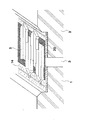
図1は、本願発明の一実施形態である舗装構造を示す概略断面図である。
この舗装構造は、連続して架設された二つのコンクリート橋桁1,2の桁遊間3上に伸縮装置等を用いることなく、舗装体4を連続して敷設したものである。この桁遊間3は、温度の変化等によって変動するものであり、両側の橋桁1,2上の所定範囲にスライディングシート18を敷設し、この上に舗装を形成して桁遊間の変動による舗装のひずみを上記スライディングシート18の敷設範囲に分散させるものである。
Hereinafter, embodiments of the invention according to the present application will be described with reference to the drawings.
FIG. 1 is a schematic sectional view showing a pavement structure according to an embodiment of the present invention.
In this pavement structure, a
この舗装構造の詳細は次のとおりである。
桁遊間の両側にあるコンクリート橋桁1,2には、桁端部における上面から所定の深さの切り欠きが設けられている。そして、この下側に桁遊間を塞ぐようにバックアップ材11が詰め込まれ、その上にシーリング材12が桁間を連結するように充填される。このシーリング材12はコンクリートに対して接着性を有するものであり、大きな弾性変形を生じ、桁遊間が変動した場合にも、桁間への漏水を防止することができるものである。
The details of this pavement structure are as follows.
The
上記切り欠きの底部は、樹脂コンクリートによる不陸調整層13が設けられ、この上にクッション材20を敷設し、その上に荷重支持部材5が配列されている。上記クッション材20は、ポリエステル不織布にアスファルトを含浸させたものであり、この上に配列される荷重支持部材5と桁1,2との相対変位が大きな抵抗なく生じるように配設されるものである。
At the bottom of the notch, a
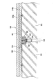
また、荷重支持部材5は、図2に示すように、鋼板材を溝型に加工した部材を桁遊間に架け渡すようにほぼ平行に多数配列することによって形成されており、隣り合う部材間で軸方向の相対変位を許容するように係合されている。そして、これらの部材は一つおきに両側で棒鋼14に係止され、樹脂コンクリート15によって桁に固定されている。したがって、桁が伸縮したときに、平行に多数配列された部材は交互に両側の桁に固定されて一体に移動するが、隣り合う部材間で摺動し、桁遊間3の変動に対応するとともに、桁遊間3が変動したときにも舗装4及び橋面の荷重を支持できるようになっている。
Further, as shown in FIG. 2, the
上記荷重支持部材5の上には、これを覆うように中埋層16が形成され、さらにその上に合成樹脂層17が形成されて、切り欠き部分の上面が桁1、2の上縁とほぼ同じ高さとなるように平坦に仕上げられている。
上記中埋層16は、図1に示すように、桁間の中央部で最も厚く、両側で徐々に薄くなるように形成されている。この中埋層16を構成する材料は、できるだけ弾性変形が生じ易く桁の伸縮に追従し得るものが望ましいが、橋面上の荷重等によって過度の変形が生じるものでは使用できず、ここでは高密度で、変形に対する追従性に優れたグースアスファルトが用いられている。
An embedded
As shown in FIG. 1, the buried
上記合成樹脂層17は、上記中埋層16の上に充填されるので、桁間の中央部で薄く、両側で徐々に厚くなっており、両側で切り欠きの傾斜面に接着されている。この合成樹脂層17を構成する材料は、大きな弾性変形を生じるとともに、コンクリートに対する接着力が大きいものが望ましく、ここでは、ウレタン変性ビニルエステル樹脂が用いられている。また、中埋層16を形成するアスファルト混合物との接着力は小さいものが望ましいが、中埋層16の上面に接着力を低減する材料を塗布したり、シート状の材料を介挿することもできる。
Since the
上記中埋層16及び合成樹脂層17は、桁遊間3が拡大したときに両層間で相対変位し、中埋層16が桁遊間3の拡大に追従できなくても、切り欠き部分の上面はほぼ平坦な状態に維持される。つまり、桁1,2と中埋層16との境界部に隙間や段差が発生するのが防止される。
The buried
上記のように、切り欠き内に中埋層16、合成樹脂層17が形成され、上面が平坦になった上にスライディングシート18が敷設される。このスライディングシートは、この上に形成される舗装体4と桁1,2との水平方向の相対移動を許容するために用いられるものである。このスライディングシート18が敷設される範囲は、桁遊間の両側の所定範囲であり、桁遊間3の変動量に応じて決定される。
As described above, the embedding
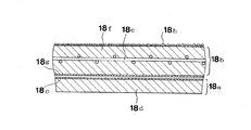
上記スライディングシート18は、図3に示すように、ポリエステルフィルム18cをゴム化アスファルト18dの薄い層の上に積層した下側シート18aと、抗張力繊維のメッシュ18eを埋込んだゴム化アスファルト18fの薄い層の下面に、ポリエステルフィルムで補強されたアルミ箔18gを貼着した上側シート18bとを重ね合わせたものであり、下側シート18aの最上層のポリエステルフィルム18cと、上側シート18bの最下層のアルミ箔18gとの間で滑動するようになっている。そして、上記スライディングシート18が敷設された範囲の縁部には、止水シート19が上記スライディングシート18の縁を覆うように敷設され、滑り面に雨水等が流入するのを防止している。
As shown in FIG. 3, the sliding
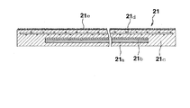
また、切り欠き部分の上には、図4に示すような、2枚の滑動用シート21a、21bを重ね合わせてゴム化アスファルト層21cに埋込んだ一層式のスライディングシート21が、上記2層式のスライディングシート18の下側に敷設され、この部分は2重に滑り層が形成されている。
Further, on the cutout portion, a single-layer
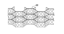
上記スライディングシート18の上には、鋼製の補強部材22が敷き並べられ、これを埋め込むように舗装4の基層4aが形成されている。
上記補強部材22は、帯状の鋼板材を折り曲げるとともに多数を接合して、図5に示すように、ハニカム状のパネルにしたものであり、高さは約20mmとなっている。この補強部材22が、桁遊間3の両側にわたって連続するように敷設され、コンクリート橋桁1,2の軸線方向における両端部は、アンカー23によって橋桁1,2に固定されている。これにより、橋桁が収縮して舗装体4に引張力が作用したときに、この引張力を負担して、舗装のアスファルト複合体に生じるひずみを分散させるものとなっている。
On the sliding
The reinforcing
上記基層4aは、主に改質アスファルトと骨材とからなる複合材料で形成され、上記ハニカム状となった補強部材22が形成する六角柱状の空間に充填されるとともに、約40mmの厚さの層に形成される。したがって、上記補強部材22を基層4aの底部に埋め込むものとなっている。
The
上記基層4aは、図7に示すように、コンクリート橋桁1,2上の補強部材22が敷設されている領域に骨材41を敷き均し、必要に応じて転圧を行った後、この上から注入材42を流し込んで骨材間の空隙に充填することによって形成されている。
As shown in FIG. 7, the
上記骨材41は、コンクリート橋桁上に敷き均したとき又は敷き均し後転圧したときの空隙率が10%から60%となるように粒径が調整されたものであり、例えば粒径が20〜13mmの砕石、粒径が13〜10mmの砕石、13〜8mmの砕石、13〜5mmの砕石、9〜6mmの砕石又は5〜2.5mmの砕石等を用いることができる。そして、このような骨材41は敷き均される前に改質アスファルトからなるプレコート材により被覆され、プレコート層43が形成されている。このプレコート材による被覆は、工場等において骨材と流動化させたプレコート材とを混合し、撹拌することによって行うことができる。
The aggregate 41 has a particle size adjusted so that the porosity is 10% to 60% when spread on a concrete bridge girder or when rolled and then rolled. A crushed stone of 20 to 13 mm, a crushed stone having a particle size of 13 to 10 mm, a crushed stone of 13 to 8 mm, a crushed stone of 13 to 5 mm, a crushed stone of 9 to 6 mm, a crushed stone of 5 to 2.5 mm, or the like can be used. Such an aggregate 41 is covered with a precoat material made of modified asphalt before being spread and a
上記プレコート材は、被覆時には流動性を有し、被覆後に硬化する材料であって、上記骨材41及び注入材42との接着性が良好な材料が選択される。そして、骨材41の表面に存在する微細な凹部に入り込んで骨材との密着性を高めるものであり、少なくと被覆時の粘性が注入時における注入材より小さいものが用いられる。本実施の形態では、アスファルトに少なくともゴム、熱可塑性エラストマー又は樹脂のうちのいずれか一つが混合された改質アスファルトが用いられており、加熱して流動化した改質アスファルトをプレコート材として骨材に被覆する。上記ゴム、熱可塑性エラストマー及び樹脂は、改質アスファルトに用いられるものとして一般に知られているものを用いることができ、その配合量を適宜に設定することができる。
The precoat material is a material that has fluidity at the time of coating and is hardened after coating, and a material that has good adhesion to the aggregate 41 and the
また、プレコート材として、上記のような加熱型の改質アスファルトの他に、例えばストレートアスファルト又はカットバックアスファルトを加熱し、流動化した状態で用いることもできる。常温でプレコート材を被覆するのが望ましい場合には、溶剤によって流動化した溶剤型改質アスファルト、アスファルト乳剤、改質アスファルト乳剤等を用いることもできる。また、明色バインダーとして舗装に用いられる材料等、注入材との付着性が良好な材料を用いることもできる。 Moreover, as a precoat material, in addition to the above-described heating-type modified asphalt, for example, straight asphalt or cutback asphalt can be heated and used in a fluidized state. When it is desirable to coat the precoat material at room temperature, solvent-type modified asphalt, asphalt emulsion, modified asphalt emulsion, etc. fluidized with a solvent can also be used. In addition, a material having good adhesion to an injection material such as a material used for pavement as a light-colored binder can be used.
上記注入材42は、アスファルトにゴム、熱可塑性エラストマー又は樹脂のうちの少なくともいずれか一つが混合された改質アスファルトであり、高温時(150℃以上)には高い流動性を有するとともに供用条件(70℃〜−10℃)で硬化性を有する加熱型改質アスファルト材を用いることができる。
The
上記改質アスファルトに用いられるゴムとしては、例えば天然ゴム、スチレン−ブタジエンゴム、クロロプレンゴム、アクリロニトリル−ブタジエンゴム等を用いることができる。また、熱可塑性エラストマーとしては、スチレン−ブタジエンブロック共重合物、スチレン−イソプレンブロック共重合物、エチレン−酢酸ビニル共重合物、アクリル酸エステル、メタクリル酸エステル等を用いることができる。樹脂としては、石油樹脂、クマロン・インデン樹脂、スチレン系樹脂等をもちいることができる。
また、このほかに石油系配合油を添加することもできる。
As the rubber used in the modified asphalt, for example, natural rubber, styrene-butadiene rubber, chloroprene rubber, acrylonitrile-butadiene rubber and the like can be used. Moreover, as a thermoplastic elastomer, a styrene-butadiene block copolymer, a styrene-isoprene block copolymer, an ethylene-vinyl acetate copolymer, an acrylic ester, a methacrylic ester and the like can be used. As the resin, petroleum resin, coumarone / indene resin, styrene resin, or the like can be used.
In addition, petroleum-based blended oil can also be added.
本実施の形態では、190℃の動粘度が50cm2/ストークス以下(50cm2/S以下)、又は170℃動粘度が100cm2ストークス以下(100cm2/S以下)、軟化点が100℃以上のものを用いている。また、ひずみが生じたときにクラックが生じにくいものが望ましく、例えばひび割れ追従性試験(道路橋床版防水便覧、社団法人 日本道路協会)等の試験結果を参考にクラックが発生し難くなるように配合を調整するのが良い。
なお、上記加熱型改質アスファルト注入材の動粘度は、舗装試験便覧(日本道路協会発行)に記載の「高温動粘度試験方法」に基づいて試験したものである。
In this embodiment, the kinematic viscosity at 190 ° C. is 50 cm 2 / Stokes or less (50 cm 2 / S or less), or the 170 ° C. kinematic viscosity is 100 cm 2 Stokes or less (100 cm 2 / S or less), and the softening point is 100 ° C. or more. Something is used. In addition, it is desirable that cracks do not easily occur when strain occurs. For example, cracks are less likely to occur with reference to the results of tests such as crack follow-up test (road bridge floor waterproofing manual, Japan Road Association). It is better to adjust the formulation.
The kinematic viscosity of the heated modified asphalt injection material was tested based on the “high temperature kinematic viscosity test method” described in the Pavement Test Manual (issued by the Japan Road Association).
上記のように物性が調整された加熱型改質アスファルトの注入材42は、骨材41が敷き均された後、加熱されて流動化したものが上方から流し込まれて骨材間を流下し、プレコート材で被覆された骨材間に隙間なく入り込んで硬化する。このとき、プレコート材で被覆された骨材は、加熱されていると注入材の充填が容易となる。骨材として粒径の小さいものを用いる場合には、加熱された注入材の温度が低下し易く、充分に充填できない場合が生じることもあるが、骨材が加熱された状態で注入することにより円滑な充填が可能となる。
The heated modified
骨材の加熱は工場等で行うことができ、加熱によって流動化するプレコート材とともに骨材を加熱及び撹拌してプレコート材の被覆を行った後、ダンプトラック等によって舗装の施工現場に搬送して所定の範囲に敷設することができる。搬送距離によって現場到着時の温度に差は生じるが、敷き均し後も100℃以上の温度が維持できる場合が多く、効率の良い施工が可能となる。 Aggregate heating can be done at factories, etc., and after heating and stirring the aggregate together with the precoat material that is fluidized by heating, the precoat material is coated, and then transported to the pavement construction site by a dump truck etc. It can be laid in a predetermined range. Although the temperature at the time of arrival at the site varies depending on the transport distance, it is often possible to maintain a temperature of 100 ° C. or higher even after laying, and efficient construction becomes possible.
上記のように注入材を充填することにより、図7に示すように骨材41と加熱型改質アスファルトからなる注入材42とが一体となったアスファルト複合体の基層4aが形成されている。そして、このようにして形成された基層4aは、加熱型改質アスファルトからなる注入材42が骨材41をしっかりと保持し、骨材41との間で剥離することなく適切な柔軟性と硬さを維持するものとなり、桁の伸縮にともなう大きな変形を許容するものとなる。
By filling the injection material as described above, an asphalt
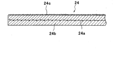
上記基層4aの上面には、ひずみ抵抗性にすぐれた拡張力シート24を貼着し、その上に表層4bを形成するアスファルト混合物が敷き均され、締め固められる。
An
上記抗張力シート24は、図6に示すように、抗張力繊維をメッシュ状に織ったもの24aをアスファルト系材料の薄い層24b内に埋め込んだものを用いている。上記抗張力繊維としては、炭素繊維、ガラス繊維、ビニロンやアラミド等の合成繊維等を用いることができる。また、アスファルト系材料はゴム化アスファルトを用いるのが望ましい。
As shown in FIG. 6, the
この抗張力シートの上面には珪砂24cがほぼ一様に付着されており、現場へ重ね合わせて又はロール状に巻いて搬入する時に、シートが互いに接着してしまうのを防止している。また、この抗張力シート24を敷設した後、表層4bのアスファルト混合物を敷き均すときに、加熱されたアスファルト混合物に上記珪砂24cが取り込まれ、確実に一体化される。
さらに、この抗張力シート24が現場に搬入される時には、下面側に剥離紙が接着されており、敷設時にはこれを剥して基層の上に敷き拡げることによって、基層4aの上面に容易に接着される。
Further, when this
表層4bは、基層4a上に抗張力シート24を介して、又は基層4a上に直接敷設されるものであり、本実施の形態では通常のアスファルト混合物を用いた密粒度舗装となっている。
なお、本実施の形態では密粒度舗装を採用したが、骨材の粒度分布とアスファルト量を調整したアスファルト混合物を用い、空隙率を大きくした開粒度舗装としてもよい。
The
In this embodiment, dense-grain pavement is adopted. However, it is also possible to use an asphalt mixture in which the particle size distribution of aggregate and the amount of asphalt are adjusted, and an open-grain pavement with an increased porosity.
以上に説明した構成の舗装構造において、桁遊間3が変動すると、舗装体の基層4a及び表層4bにひずみが生じる。しかし、スライディングシート18が敷設された範囲で舗装体4は桁上を滑動できるものとなっており、基層4a内の骨材41、プレコート層43、及び加熱型改質アスファルトからなる注入材42が一体となって引張力を負担し、引張ひずみが分散されて大きなひびわれの発生が防止される。また、基層4aと表層4bとの間に抗張力シート24が介挿されており、この部分でもひずみは分散されるとともに、局部的に大きなひずみが発生するのが防止される。
In the pavement structure having the above-described configuration, when the girder gap 3 varies, distortion occurs in the
なお、本実施の形態では、空隙率が10%〜60%となるように基層4aの骨材の粒径を選択し、骨材によって荷重を支持する骨格を形成している。したがって、空隙率が60%以上になると骨材の量が不足し、荷重に抵抗することが困難となって変形が大きくなってしまう。また、空隙率が10%以下となると加熱型改質アスファルト注入材の骨材間への流れ込みが滞留しがちになり、空隙が残留して耐久性が劣ることになりやすい。このような観点から、空隙率は40%〜50%とするのが望ましい。
In the present embodiment, the particle size of the aggregate of the
図8は、本願発明の他の実施形態である舗装構造を示す概略断面図である。
この舗装構造は、桁遊間の変動が小さい場合、又は桁の伸縮による桁遊間の変動はなく、活荷重の載荷にともなう桁のたわみによって桁遊間が変動する場合等に採用されるものである。
FIG. 8 is a schematic sectional view showing a pavement structure according to another embodiment of the present invention.
This pavement structure is employed when there is little variation between girders, or when there is no variation between girders due to the expansion and contraction of the girders, and when there is variation between girders due to deflection of the girders when live loads are applied.
この舗装構造では、桁遊間53の上部にバックアップ材56が詰め込まれ、その上にシーリング材57が二つの桁51,52間を連結するように充填されている。そして、桁遊間53の両側の桁51,52上部に設けられた切り欠き内には樹脂モルタル55(又は樹脂コンクリート)が充填されている。この樹脂モルタル55は、桁51,52のコンクリートと一体とされるとともに、桁遊間上には目地材58が介挿され、両側の桁51,52の相対変位を許容するとともに桁遊間上の舗装体54を支持するようになっている。
In this pavement structure, a back-up
この樹脂コンクリート55の上には、図1に示す舗装構造と同様にスライディングシート59が敷設され、補強部材61が埋め込まれた基層54aが設けられ、さらに抗張力シート60を介して表層54bが積層されている。
この舗装体54及び抗張力シート60の構成は、図1に示す舗装構造と同じものが用いられており、敷設の方法等も同じである。
このような構成とすることで、図1に示す舗装構造と同様に、耐久性に優れた舗装構造とすることができる。
A sliding
The structure of the
By setting it as such a structure, it can be set as the pavement structure excellent in durability similarly to the pavement structure shown in FIG.
1:橋桁、 2:橋桁、 3:桁遊間、 4:舗装体、 4a:基層、 4b:表層、 5:荷重支持部材、 11:バックアップ材、 12:シーリング材、 13:不陸調整層、 14:棒鋼、 15:樹脂コンクリート、 16:中埋層、 17:合成樹脂層、 18:スライディングシート、 19:止水シート、 20:クッション材、 21:一層式のスライディングシート、 22:補強部材、 23:アンカー、 24:抗張力シート、
41:骨材、 42:注入材、 43:プレコート層、
51,52:桁、 53:桁遊間、 54:舗装体、 55:樹脂モルタル、 56:バックアップ材、 57:シーリング材、 59:スライディングシート、 60:抗張力シート、 61:補強部材
1: bridge girder, 2: bridge girder, 3: girder gap, 4: pavement, 4a: base layer, 4b: surface layer, 5: load support member, 11: backup material, 12: sealing material, 13: non-land adjustment layer, 14 : Steel bar, 15: Resin concrete, 16: Filled layer, 17: Synthetic resin layer, 18: Sliding sheet, 19: Waterproof sheet, 20: Cushion material, 21: Single-layer sliding sheet, 22: Reinforcement member, 23 : Anchor, 24: Tensile sheet,
41: aggregate, 42: injection material, 43: precoat layer,
51, 52: Girder, 53: Girder play, 54: Pavement, 55: Resin mortar, 56: Backup material, 57: Sealing material, 59: Sliding sheet, 60: Tensile sheet, 61: Reinforcement member
Claims (4)
前記桁遊間の両側にあるコンクリート構造体上に、該コンクリート構造体とこの上に敷設される舗装体との間の水平方向の相対変位を許容するスライディングシートが敷設され、
前記舗装体は基層と表層とを積層したものであって、該基層と該表層とが前記桁遊間上の位置の両側にわたって連続するように敷設され、
前記基層は、
敷き均したときの空隙率が10%〜60%となるように粒度が調整された骨材を、アスファルトを主成分とするプレコート材によって予め被覆し、
該骨材を前記スライディングシートの上に敷き均し、
アスファルトに少なくともゴムと熱可塑性エラストマーと樹脂とのうちのいずれか一つを混合し、加熱して流動化した注入材を、敷きならした前記骨材の上から流し込み、該骨材間の空隙に充填して硬化させたものであることを特徴とする舗装構造。 A pavement structure in which pavements are continuously laid on the girder gap,
On the concrete structures on both sides of the girders, a sliding sheet that allows horizontal relative displacement between the concrete structures and the pavement laid on the concrete structures is laid.
The pavement is a laminate of a base layer and a surface layer, and the base layer and the surface layer are laid so as to be continuous over both sides of the position between the girders,
The base layer is
Covering the aggregate whose particle size is adjusted so that the porosity when it is leveled is 10% to 60%, with a precoat material mainly composed of asphalt,
Spread the aggregate on the sliding sheet,
At least one of rubber, thermoplastic elastomer and resin is mixed in asphalt, and the injection material fluidized by heating is poured from above the aggregate that has been spread, and into the gap between the aggregates. A pavement structure characterized by being filled and cured.
該骨材を路盤又はコンクリート構造体上に敷き均し、
アスファルトに少なくともゴムと熱可塑性エラストマーと樹脂とのうちのいずれか一つを混合し、加熱して流動化した注入材を、敷きならした前記骨材の上から流し込み、該骨材間の空隙に充填し、硬化させて基層を形成し、
該基層の上にアスファルト混合物からなる表層を敷設したことを特徴とする舗装体の形成方法。
Covering the aggregate whose particle size is adjusted so that the porosity when it is leveled is 10% to 60%, with a precoat material mainly composed of asphalt,
Spread the aggregate on the roadbed or concrete structure,
At least one of rubber, thermoplastic elastomer and resin is mixed in asphalt, and the injection material fluidized by heating is poured from above the aggregate that has been spread, and into the gap between the aggregates. Filling and curing to form a base layer,
A method for forming a pavement, wherein a surface layer made of an asphalt mixture is laid on the base layer.
Priority Applications (1)
| Application Number | Priority Date | Filing Date | Title |
|---|---|---|---|
| JP2008252482A JP5113003B2 (en) | 2008-09-30 | 2008-09-30 | Pavement structure and method for forming pavement |
Applications Claiming Priority (1)
| Application Number | Priority Date | Filing Date | Title |
|---|---|---|---|
| JP2008252482A JP5113003B2 (en) | 2008-09-30 | 2008-09-30 | Pavement structure and method for forming pavement |
Publications (2)
| Publication Number | Publication Date |
|---|---|
| JP2010084355A JP2010084355A (en) | 2010-04-15 |
| JP5113003B2 true JP5113003B2 (en) | 2013-01-09 |
Family
ID=42248592
Family Applications (1)
| Application Number | Title | Priority Date | Filing Date |
|---|---|---|---|
| JP2008252482A Active JP5113003B2 (en) | 2008-09-30 | 2008-09-30 | Pavement structure and method for forming pavement |
Country Status (1)
| Country | Link |
|---|---|
| JP (1) | JP5113003B2 (en) |
Families Citing this family (9)
| Publication number | Priority date | Publication date | Assignee | Title |
|---|---|---|---|---|
| KR101177890B1 (en) * | 2011-07-08 | 2012-08-28 | 김은령 | Road paving materials having water permeability and paving method using the same |
| JP5977049B2 (en) * | 2012-03-12 | 2016-08-24 | 正成 稲葉 | Pavement formation method |
| JP5738819B2 (en) * | 2012-10-01 | 2015-06-24 | 西日本高速道路株式会社 | Water stop structure |
| JP6680577B2 (en) * | 2016-03-10 | 2020-04-15 | 勲 田崎 | Guided drainage method for surface water on pavement surface and guided drainage of surface water |
| JP6712473B2 (en) * | 2016-03-10 | 2020-06-24 | 勲 田崎 | Drainage repair method for the defect on the pavement surface and drainage repair structure for the defect |
| JP6095842B1 (en) * | 2016-11-21 | 2017-03-15 | 福美建設株式会社 | Bridge floor slab water stop, floor slab waterproof structure |
| CN108824184A (en) * | 2018-08-21 | 2018-11-16 | 长沙理工大学 | Height-adjustable UHPC bridge extension joint |
| CN115522427B (en) * | 2022-10-09 | 2024-12-27 | 江苏中路工程技术研究院有限公司 | Deformation joint expansion device, pavement structure and construction method of pavement structure |
| CN119977500B (en) * | 2025-04-14 | 2025-06-27 | 安徽省交通规划设计研究总院股份有限公司 | A copper-doped tailings road base material and its proportion confirmation method and application |
Family Cites Families (6)
| Publication number | Priority date | Publication date | Assignee | Title |
|---|---|---|---|---|
| JPS61191703A (en) * | 1985-02-19 | 1986-08-26 | 横浜ゴム株式会社 | Construction of expansion joint for road |
| JPH0250404U (en) * | 1988-09-30 | 1990-04-09 | ||
| JPH0393807U (en) * | 1990-01-05 | 1991-09-25 | ||
| JP4012608B2 (en) * | 1997-09-24 | 2007-11-21 | 正成 稲葉 | Continuous pavement structure of bridge surface |
| JP4071324B2 (en) * | 1997-09-24 | 2008-04-02 | 正成 稲葉 | Continuous pavement structure of bridge surface |
| JP3981582B2 (en) * | 2002-03-26 | 2007-09-26 | 武男 稲葉 | Pavement structure and method for forming pavement |
-
2008
- 2008-09-30 JP JP2008252482A patent/JP5113003B2/en active Active
Also Published As
| Publication number | Publication date |
|---|---|
| JP2010084355A (en) | 2010-04-15 |
Similar Documents
| Publication | Publication Date | Title |
|---|---|---|
| JP5113003B2 (en) | Pavement structure and method for forming pavement | |
| JP5852353B2 (en) | Telescopic device used for bridge and method for manufacturing the same | |
| JP6008725B2 (en) | Road structure at the boundary between road structure and embankment | |
| US8789340B2 (en) | Surface underlayment | |
| US20170058469A1 (en) | Joint structure at end of concrete floor slab of bridge | |
| JP6148156B2 (en) | Construction method of buried type expansion device, bridge and buried type expansion device | |
| JP5977049B2 (en) | Pavement formation method | |
| JPH08151602A (en) | Road construction at boundary between structure and filling | |
| JP4927681B2 (en) | Pavement structure | |
| JP4012608B2 (en) | Continuous pavement structure of bridge surface | |
| JP3981582B2 (en) | Pavement structure and method for forming pavement | |
| JP2014080853A (en) | Construction method of resin pavement body in road joint part, and road joint part structure comprised of resin pavement body | |
| JP4071324B2 (en) | Continuous pavement structure of bridge surface | |
| JP2015067982A (en) | Rubber concrete for road bridge and construction method therefor, and expansion device using rubber concrete for road bridge | |
| JP2014240575A (en) | Embedment type joint part structure for bridge and construction method therefor | |
| JP2005171730A (en) | Waterproof structure of floor slab pavement | |
| JP6883416B2 (en) | Buried joints for bridges and buried joint structures | |
| JP5620687B2 (en) | Telescopic device used for bridge and method for manufacturing the same | |
| JP3137475B2 (en) | Pavement of bridge surface and continuous pavement method of bridge surface | |
| CN110004817A (en) | Seamless anti-vehicle-jumping structure at end part of small-and-medium-span simply-supported highway bridge and construction method thereof | |
| KR100408895B1 (en) | Construction method of expansion joint for bridge | |
| KR20200055888A (en) | Expansion joint construction method of bridge or concrete structure using elastic seal material and carbon fiber | |
| Haynes et al. | Selection of the most effective pavement surfacing strategy for the Glenwood cross laminated timber parking garage | |
| JPH1193106A (en) | Paving structure for expansion spacing of highway bridge | |
| RU2828718C1 (en) | Bridge structure roadway formation method |
Legal Events
| Date | Code | Title | Description |
|---|---|---|---|
| A621 | Written request for application examination |
Free format text: JAPANESE INTERMEDIATE CODE: A621 Effective date: 20110825 |
|
| A977 | Report on retrieval |
Free format text: JAPANESE INTERMEDIATE CODE: A971007 Effective date: 20120924 |
|
| TRDD | Decision of grant or rejection written | ||
| A01 | Written decision to grant a patent or to grant a registration (utility model) |
Free format text: JAPANESE INTERMEDIATE CODE: A01 Effective date: 20121002 |
|
| A01 | Written decision to grant a patent or to grant a registration (utility model) |
Free format text: JAPANESE INTERMEDIATE CODE: A01 |
|
| A61 | First payment of annual fees (during grant procedure) |
Free format text: JAPANESE INTERMEDIATE CODE: A61 Effective date: 20121011 |
|
| FPAY | Renewal fee payment (event date is renewal date of database) |
Free format text: PAYMENT UNTIL: 20171019 Year of fee payment: 5 |
|
| R150 | Certificate of patent or registration of utility model |
Ref document number: 5113003 Country of ref document: JP Free format text: JAPANESE INTERMEDIATE CODE: R150 Free format text: JAPANESE INTERMEDIATE CODE: R150 |
|
| R250 | Receipt of annual fees |
Free format text: JAPANESE INTERMEDIATE CODE: R250 |
|
| R250 | Receipt of annual fees |
Free format text: JAPANESE INTERMEDIATE CODE: R250 |
|
| S531 | Written request for registration of change of domicile |
Free format text: JAPANESE INTERMEDIATE CODE: R313531 |
|
| R350 | Written notification of registration of transfer |
Free format text: JAPANESE INTERMEDIATE CODE: R350 |
|
| R250 | Receipt of annual fees |
Free format text: JAPANESE INTERMEDIATE CODE: R250 |