JP5111755B2 - Straight guide mounting device - Google Patents
Straight guide mounting device Download PDFInfo
- Publication number
- JP5111755B2 JP5111755B2 JP2005340068A JP2005340068A JP5111755B2 JP 5111755 B2 JP5111755 B2 JP 5111755B2 JP 2005340068 A JP2005340068 A JP 2005340068A JP 2005340068 A JP2005340068 A JP 2005340068A JP 5111755 B2 JP5111755 B2 JP 5111755B2
- Authority
- JP
- Japan
- Prior art keywords
- spindle
- slider
- linear guide
- driving direction
- fixed
- Prior art date
- Legal status (The legal status is an assumption and is not a legal conclusion. Google has not performed a legal analysis and makes no representation as to the accuracy of the status listed.)
- Active
Links
Images


Description
本発明は直線ガイド搭載装置、特にそのスピンドル取付機構の改良に関する。 The present invention relates to a linear guide mounting device, and more particularly to an improvement of its spindle mounting mechanism.
従来より、形状の精密測定を行うため、直線ガイドを使った、例えば三次元測定機等の高精度測定機(直線ガイド搭載装置)が用いられている。
三次元測定機は、互いに直交するガイドと、該ガイドの移動量を求めるスケール及びプローブをもち、それぞれの移動量からプローブの三次元座標値を求めるものである。
測定によって得られるものは、ワークのXYZ座標値であり、その座標値から必要とする穴径や穴位置・段差などの寸法は、コンピュータによるデータ処理によって求められる。
Conventionally, a high-precision measuring machine (straight guide mounting device) using a linear guide, such as a three-dimensional measuring machine, has been used to accurately measure the shape.
The three-dimensional measuring machine has a guide orthogonal to each other, a scale and a probe for obtaining the movement amount of the guide, and obtains a three-dimensional coordinate value of the probe from each movement amount.
What is obtained by the measurement is the XYZ coordinate value of the workpiece, and the required hole diameter, hole position, level difference and the like are obtained from the coordinate value by data processing by a computer.
ところで、従来、高精度測定機は、設置環境として、例えば20±0.5℃クラスの高水準な恒温室が必要であった。 By the way, conventionally, a high-precision measuring machine has required a high-level constant temperature room of, for example, 20 ± 0.5 ° C. as an installation environment.
しかしながら、最近は、環境設備費やランニングコストの低減のため、高精度測定機には、より広い温度範囲での精度保証を可能とすることが求められている。 However, recently, in order to reduce environmental equipment costs and running costs, high precision measuring instruments are required to be able to guarantee accuracy over a wider temperature range.
この要望に応えるため、直線ガイドを使った高精度測定機では、温度補正機能を備えており、温度補正機能により測定結果を例えば20℃の寸法に換算して出力している。 In order to meet this demand, a high precision measuring machine using a linear guide has a temperature correction function, and the temperature correction function converts the measurement result into, for example, a dimension of 20 ° C. and outputs it.
ところで、温度補正機能は、広い温度範囲での精度保証を試みるものである。
しかしながら、本発明者らによれば、単に温度補正機能を用いただけでは、精度の面で不十分な点がある。
すなわち、温度補正機能は、測定機本体の幾何精度の変化が少ないことが前提であり、このような前提があってはじめて、満足のゆく温度補正機能が有効になるものである。
しかしながら、従来、幾何精度変化の低減は改善の余地が残されていた。
By the way, the temperature correction function tries to guarantee accuracy in a wide temperature range.
However, according to the present inventors, there is an insufficient point in terms of accuracy if only the temperature correction function is used.
That is, the temperature correction function is based on the premise that there is little change in the geometric accuracy of the main body of the measuring machine, and a satisfactory temperature correction function is effective only when such a premise is provided.
Conventionally, however, there has been room for improvement in reducing the change in geometric accuracy.
ここで、従来は、幾何精度変化の低減のため、例えば以下に示されるような材質の工夫、構造の工夫による先行技術が存在する。
従来は、材質の工夫に関し、熱変形を防止するためにアルミニウム合金によって三次元測定機を構成する技術もある(例えば、特許文献1参照)。
また従来は、構造の工夫に関し、板ばねによって熱変形を吸収させる技術(例えば、特許文献2参照)、平行板ばね機構によってスケールの長手方向弾性変形を許容する技術(例えば、特許文献3参照)、変形を吸収することのできるガイドレールの支承手段に関する技術(例えば、特許文献4参照)もある。
従来は、高精度測定機において、例えば特許公報1〜4に記載の技術を適用し、幾何精度の変化の低減化を試みることが考えられる。
Here, in the past, there are prior arts based on, for example, the materials and structures as shown below in order to reduce the change in geometric accuracy.
Conventionally, there is also a technique for configuring a three-dimensional measuring machine with an aluminum alloy in order to prevent thermal deformation with regard to the device of the material (for example, see Patent Document 1).
Conventionally, regarding the device of the structure, a technique for absorbing thermal deformation by a leaf spring (see, for example, Patent Document 2), and a technique for allowing elastic deformation in the longitudinal direction of a scale by a parallel leaf spring mechanism (for example, see Patent Document 3). There is also a technique (for example, see Patent Document 4) related to a guide rail supporting means capable of absorbing deformation.
Conventionally, it is conceivable to attempt to reduce the change in geometric accuracy by applying the techniques described in
しかしながら、前記従来方式にあっても、幾何精度変化の低減は、いまだ改善の余地が残されており、広温度域における高精度化も改善の余地が残されていた。また幾何精度の向上を実現することのできる有効な鍵も、いまだ不明であった。
また前記従来方式では、広温度域における高精度化は困難であるので、直線ガイド搭載装置の高速化、メンテナンスフリー化も困難であった。
However, even in the conventional method, there is still room for improvement in reducing the change in geometric accuracy, and there is room for improvement in improving accuracy in a wide temperature range. Also, an effective key that can improve the geometric accuracy is still unknown.
In the conventional method, it is difficult to achieve high accuracy in a wide temperature range, so it is difficult to increase the speed and maintenance-free of the linear guide mounting device.
すなわち、材質のみに注目し、直線ガイド搭載装置において、特許文献1に記載の技術を採用したのでは、送り方向ないし直交方向の剛性を落としてしまう。このような機械の剛性低下も高精度化を妨げる。
一方、構造のみに注目し、直線ガイド搭載装置において、特許文献2〜4に記載の技術を試行錯誤で採用しても、従来は幾何精度の向上を実現することのできる有効な鍵がいまだ不明である以上、高精度化を確実に図るのは困難である。
That is, paying attention only to the material and adopting the technique described in
On the other hand, paying attention only to the structure, even if the techniques described in
本発明は前記従来技術の課題に鑑みなされたものであり、その目的は、広温度域における高精度化を確実に図ることのできる直線ガイド搭載装置を提供することにある。 The present invention has been made in view of the above-described problems of the prior art, and an object thereof is to provide a linear guide mounting device that can reliably achieve high accuracy in a wide temperature range.
本発明者らが、直線ガイド搭載装置において、広温度域における高精度化を図るため、検討を重ねた結果、まず機械の剛性確保と、熱影響の低減化との両立が非常に重要である点に到達した。
そして、本発明者らが、機械の剛性確保と熱影響低減化との両立について検討の結果、以下に示されるように、機械の剛性確保と熱影響低減化との両立に最も有効な部材の特定、剛性確保のための材質の選択、及び熱影響の低減化機構の組み合わせが非常に重要である点に到達した。
As a result of repeated investigations by the present inventors in order to achieve high accuracy in a wide temperature range in the linear guide mounting device, it is very important to first ensure the rigidity of the machine and reduce the thermal effect. Reached the point.
And, as a result of studying the coexistence of ensuring the rigidity of the machine and reducing the thermal effect, the present inventors, as shown below, are the most effective members for coexisting the ensuring of the rigidity of the machine and reducing the thermal effect. We have reached the point where the combination of identification, material selection for securing rigidity, and the mechanism for reducing the thermal effect is very important.
<部材の特定>
すなわち、従来は、熱の影響を低減化するため、部材としてはベース、スライダが注目されており、このベース、スライダに対し、材質の工夫等を行うことが常套手段であった。
これに対し、本発明は、機械の剛性確保と熱影響低減化との両立を図ることを目的として、数ある部材の中から、有効な部材を検討した結果、スピンドルとスライダ間が非常に有効である点に至った。
<材質の選択>
また本発明は、機械の剛性確保と熱影響低減化との両立を図ることを目的として、数ある部材の材質の中から、スライダには軽量化の点で優れた例えばアルミ合金を用い、スピンドルには軽量化と高剛性との点で優れた炭素繊維強化プラスチック等を選択している。
<熱影響低減化機構の付加>
また本発明は、機械の剛性確保と熱影響低減化との両立を図ることを目的として、数ある対策の中から、変形を逃がす手法を選択している。
<Identification of parts>
That is, conventionally, in order to reduce the influence of heat, attention has been paid to a base and a slider as members, and it has been common practice to devise materials for the base and the slider.
On the other hand, the present invention, as a result of investigating effective members from among a number of members for the purpose of ensuring the rigidity of the machine and reducing the thermal effect, results in a very effective space between the spindle and the slider. It came to the point.
<Selection of material>
In addition, the present invention uses an aluminum alloy, for example, which is superior in terms of weight reduction, among the materials of a number of members, for the purpose of achieving both the rigidity of the machine and the reduction of the thermal effect. Is selected from carbon fiber reinforced plastics that are superior in terms of weight reduction and high rigidity.
<Addition of thermal effect reduction mechanism>
In the present invention, for the purpose of achieving both of ensuring the rigidity of the machine and reducing the thermal effect, a method for escaping deformation is selected from among various measures.
このようにして本発明者らは、直線ガイド搭載装置において、広温度域における高精度化を図るためには、機械の剛性確保と熱影響低減化との両立が非常に重要である点、前記部材の特定、材質の選択、熱影響低減化機構の付加の組み合わせによりはじめて、機械の剛性確保と熱影響低減化との両立が確実に行える点を見出し、本発明を完成するに至った。 Thus, in the linear guide mounting apparatus, in order to achieve high accuracy in a wide temperature range, it is very important to ensure both the rigidity of the machine and the reduction of the thermal effect, Only by the combination of the identification of the member, the selection of the material, and the addition of a mechanism for reducing the thermal effect, the present inventors have found that both the rigidity of the machine can be reliably ensured and the thermal effect can be reduced, and the present invention has been completed.
すなわち、前記目的を達成するために本発明にかかる直線ガイド搭載装置は、ベースと、直線ガイドと、スライダと、スピンドルと、を備えた直線ガイド搭載装置において、該スライダは、アルミ合金で形成され、前記スピンドルは、炭素繊維強化プラスチックで形成される。前記ガイド搭載装置は、前記スライダに前記スピンドルを取り付けるためのスピンドル取付機構を備える。前記スピンドル取付機構は、固定側スピンドル取付手段、及び逃げ側スピンドル取付手段を備える。前記スピンドル取付機構は、前記スライダないし前記スピンドルの前記駆動方向に平行な方向への熱変形が生じようとしても、該逃げ側スピンドル取付手段が、該熱変形を該駆動方向に平行な方向に逃がすことを特徴とする。 That is, in order to achieve the above object, a linear guide mounting device according to the present invention is a linear guide mounting device including a base, a linear guide, a slider, and a spindle, and the slider is made of an aluminum alloy. The spindle is made of carbon fiber reinforced plastic . The guide mounting device includes a spindle mounting mechanism for mounting the spindle to the slider. The spindle mounting mechanism includes a fixed-side spindle mounting means and a relief-side spindle mounting means. The spindle mounting mechanism allows the escape side spindle mounting means to release the thermal deformation in a direction parallel to the driving direction even if thermal deformation occurs in a direction parallel to the driving direction of the slider or the spindle. It is characterized by that.
ここで、前記直線ガイドは、前記ベースに対し所定の駆動方向に沿って設けられる。
また前記スライダは、前記直線ガイド上に設けられ、前記駆動方向に直線移動する。
前記スピンドルは、前記スライダと共に前記駆動方向に直線移動するように該スライダに設けられ、ワークにアプローチするためのツールを先端に保持する。
Here, the linear guide is provided along a predetermined driving direction with respect to the base.
The slider is provided on the linear guide and linearly moves in the driving direction.
The spindle is provided on the slider so as to move linearly in the driving direction together with the slider, and holds a tool for approaching the workpiece at the tip.
前記固定側スピンドル取付手段は、前記駆動方向に平行な方向に所定の離隔距離をおいて配置され、前記スライダに前記スピンドルを固定状態で保持する。
前記逃げ側スピンドル取付手段は、前記スライダないし前記スピンドルを前記所定駆動方向のみにスライド自在に保持する。
The fixed-side spindle mounting means is disposed at a predetermined separation distance in a direction parallel to the driving direction, and holds the spindle in a fixed state on the slider.
The escape side spindle mounting means holds the slider or the spindle slidably only in the predetermined driving direction.
なお、本発明においては、前記逃げ側スピンドル取付手段が、逃げ側保持部材と、板バネと、を含むことが好適である。
ここで、前記逃げ側保持部材は、前記スライダに設けられ、前記スピンドルないし該スライダを前記駆動方向に平行な方向のみに相対的にスライド自在に保持する。
また前記板バネは、前記スピンドルないし前記スライダを前記駆動方向に平行な方向のみに相対的に変位させる。
In the present invention, the relief-side spindle attachment means, and a flank-side holding member, may comprise a plate wave Ne, which is the preferred.
Here, the escape side holding member is provided on the slider, and holds the spindle or the slider relatively slidably only in a direction parallel to the driving direction.
Also, the plate bar roots, to relatively displace only in the direction parallel to the spindle or the slider to the drive direction.
また、本発明においては、前記固定側スピンドル取付手段が、前記駆動方向と直交する方向から前記スピンドルを面で固定挟持する、少なくとも一対の固定側保持部材を備える。
前記逃げ側保持部材は、前記駆動方向と直交する方向から前記スピンドルを面で挟持する、少なくとも一対のものである。
本発明においては、前記逃げ側保持部材端部にそれぞれ前記板ばねの端部が固定され、該板ばねの中央部が前記スピンドルの端部に固定されていることが好適である。
In the present invention, the fixed-side spindle mounting means includes at least a pair of fixed-side holding members that fixedly clamp the spindle with a surface from a direction orthogonal to the driving direction.
The escape side holding member is at least a pair of members that sandwich the spindle with a surface from a direction orthogonal to the driving direction.
In the present invention, it is preferable that an end portion of the leaf spring is fixed to an end portion of the escape side holding member, and a center portion of the leaf spring is fixed to an end portion of the spindle.
本発明においては、前記ツールは、前記スピンドルの先端に設けられ、前記ワーク上の三次元座標を検出するためのプローブを含む。前記直線ガイド搭載装置は、前記ワーク上の三次元座標値を求める三次元測定を行うことが好適である。 In the present invention, the tool includes a probe that is provided at a tip of the spindle and detects a three-dimensional coordinate on the workpiece. The linear guide mounting device preferably performs three-dimensional measurement to obtain a three-dimensional coordinate value on the workpiece.
本発明にかかる直線ガイド搭載装置によれば、前記スピンドルと前記スライダとにそれぞれ最適な材質を選択し、かつ該スピンドルと該スライダ間に前記スピンドル取付機構を備えることとしたので、広温度域における機械の高精度化を図ることができる。
また本発明にかかる直線ガイド搭載装置によれば、高速化、メンテナンスフリー化を図ることもできる。
According to the linear guide mounting device of the present invention, the optimum material is selected for each of the spindle and the slider, and the spindle mounting mechanism is provided between the spindle and the slider. High precision of the machine can be achieved.
Moreover, according to the linear guide mounting apparatus concerning this invention, speed-up and maintenance-free can also be achieved.
また本発明においては、前記逃げ側スピンドル取付手段が、板ばねないし直線ガイドを含むことにより、前記広温度域における高精度化を、より確実に図ることができる。 In the present invention, the escape side spindle mounting means includes a leaf spring or a linear guide, so that high accuracy in the wide temperature range can be achieved more reliably.
また本発明においては、前記固定側保持部材、前記逃げ側保持部材を備えることにより、前記広温度域における高精度化を、より確実に図ることができる。 Further, in the present invention, by providing the fixed side holding member and the flank side holding member, high accuracy in the wide temperature range can be achieved more reliably.
本発明においては、三次元測定機のスピンドルとスライダ間に前記スピンドル取付機構を設けることにより、三次元測定機において、広温度域における高精度化を、より確実に図ることができる。 In the present invention, by providing the spindle mounting mechanism between the spindle and the slider of the coordinate measuring machine, high accuracy in a wide temperature range can be achieved more reliably in the coordinate measuring machine.
以下、図面に基づき本発明の好適な一実施形態について説明する。
図1には本発明の一実施形態にかかる直線ガイド搭載装置の概略構成が示されている。
同図に示す三次元測定機(直線ガイド搭載装置)10は、ベース12と、直線ガイド14及びスライドブロック16と、スライダ18と、スピンドル20と、を備える。
Hereinafter, a preferred embodiment of the present invention will be described with reference to the drawings.
FIG. 1 shows a schematic configuration of a linear guide mounting device according to an embodiment of the present invention.
A coordinate measuring machine (straight guide mounting device) 10 shown in FIG. 1 includes a base 12, a
ここで、ベース12は、例えば三次元測定機10のZ軸ガイド22を含む。
Here, the base 12 includes, for example, the Z-
また、直線ガイド14は、ベース12に対しZ軸(上下方向)に沿って設けられる。
スライドブロック16は、直線ガイド14上に設けられ、Z方向に直線移動する。
The
The
またスライダ18は、スライドブロック16上に設けられ、Z軸方向に直線移動する。
スピンドル20は、例えばZ軸スピンドル等よりなり、スライダ18と共にZ軸方向に直線移動するようにスライダ18に設けられ、ワーク24の座標位置情報を得るための検出器であるプローブ(ツール)26を、先端に保持する。
The
The
本実施形態において特徴的なことは、機械の強度確保と熱影響低減との両立を図るため、
スライダ18を、該スライダ18の要求性能に基づき選択された材質で構成し、スピンドル20を、該スピンドル20の要求性能に基づき選択された材質で構成し、かつスライダ18とスピンドル20間にスピンドル取付機構30を備えたことである。
例えばスライダ18には、軽量化に優れた例えばアルミ合金を用い、スピンドル20には軽量化と高剛性とに優れた炭素繊維強化プラスチック等を用いている。
スピンドル取付機構30は、固定側スピンドル取付手段32と、逃げ側スピンドル取付手段34と、を備える。
ここで、固定側スピンドル取付手段32は、Z軸方向に所定離隔距離をおいて配置され、スライダ18にスピンドル20を固定状態で保持するためのものとする。
また逃げ側スピンドル取付手段34は、スライダ18ないしスピンドル20をZ軸方向のみにスライド自在に保持する。
What is characteristic in this embodiment is to achieve both of ensuring the strength of the machine and reducing thermal effects.
The
For example, the
The
Here, the fixed-side spindle mounting means 32 is disposed at a predetermined separation distance in the Z-axis direction, and is used to hold the
The escape side spindle mounting means 34 holds the
そして、スピンドル取付機構30は、スライダ18ないしスピンドル20の上下方向への熱変形が生じようとしても、逃げ側スピンドル取付手段34が、熱変形を上下方向に逃がす。
In the
<三次元測定機>
なお、本実施形態においては、三次元測定機10が、互いに直交するX軸ガイド40,Y軸ガイド42、Z軸ガイド22と、各ガイド40,42,22の移動量を求めるためのプローブ26と、を備える。三次元測定機10は、プローブ26等で得られたそれぞれの移動量からプローブ26の三次元座標値を求める。
また、本実施形態においては、スピンドル20が、四角柱体よりなる。
<CMM>
In the present embodiment, the coordinate measuring
In the present embodiment, the
<温度補正手段>
また本実施形態においては、広範囲な温度環境下での高精度測定を実現するため、温度補正手段50を備えることが好適である。
ここで、温度補正手段50は、例えばコンピュータ52等よりなり、温度センサ54で検出した温度データと、あらかじめ設定しておいたワーク24の線膨張係数等をもとに、評価手段56で求められた測定結果を20℃時に換算して、これを温度補正済み測定結果として出力する。
<Temperature correction means>
In the present embodiment, it is preferable to include the temperature correction means 50 in order to realize high-accuracy measurement under a wide range of temperature environments.
Here, the temperature correction means 50 is composed of, for example, a computer 52 or the like, and is obtained by the evaluation means 56 based on the temperature data detected by the temperature sensor 54 and the linear expansion coefficient of the
スピンドル取付機構
以下に本実施形態において特徴的なスピンドル取付機構30について、より具体的に説明する。
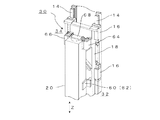
図2には、本実施形態において特徴的なスピンドル取付機構30の要部の拡大図が示されている。
同図において、スピンドル取付機構30は、固定側スピンドル取付手段32と、逃げ側スピンドル取付手段34と、を備える。
Spindle Mounting Mechanism The
FIG. 2 is an enlarged view of a main part of the
In the figure, the
<固定側スピンドル取付手段>
固定側スピンドル取付手段30は、Z軸方向と直交する方向からスピンドル20を面で固定挟持する、少なくとも一対の固定側保持部材60(62)を備える。
<Fixing means for fixed side spindle>
The fixed-side spindle mounting means 30 includes at least a pair of fixed-side holding members 60 (62) that fixedly clamp the
<逃げ側スピンドル取付手段>
逃げ側スピンドル取付手段34は、逃げ側保持部材64,66と、板ばね68と、を含むことが好適である。
ここで、逃げ側保持部材64,66は、少なくとも一対のものであり、スピンドル20ないしスライダ18を、Z軸方向のみに相対的にスライド自在に、スライダ18にスピンドル20を保持する。
本実施形態においては、逃げ側保持部材64,66が、Z軸方向と直交する方向から、四角柱状のスピンドル20の側壁を面で挟持する。
また、板ばね68は、スピンドル20ないしスライダ18をZ軸方向のみに相対的に変位させる。
本実施形態においては、逃げ側保持部材64,66にそれぞれ板ばね68端部が固定され、板ばね68中央部がスピンドル20の端部に固定されていることが好適である。
<Escape side spindle mounting means>
The escape side spindle mounting means 34 preferably includes escape
Here, the escape
In the present embodiment, the escape
The leaf spring 68 relatively displaces the
In the present embodiment, it is preferable that the end portions of the leaf springs 68 are fixed to the escape
本実施形態にかかる三次元測定機10は概略以上のように構成され、以下にその作用について説明する。
すなわち、本実施形態は、機械の剛性確保と熱影響低減化との両立のため、対策の対象となる部材としてスライダ18とスピンドル20間を特定し、その材質としてスライダ18には軽量化を図るため例えばアルミ合金を用い、スピンドル20には軽量化と高剛性のため炭素繊維強化プラスチック(CFRP:carbon fiber reinforced plastic)等を選択した。そして、スライダ18とスピンドル20間の取付箇所の一端に、長手方向伸びの変位(駆動方向と平行した方向のバイメタルの影響)を逃がす板ばね68等の逃げ側スピンドル取付手段34を設けている。
The coordinate measuring
That is, in this embodiment, in order to achieve both the rigidity of the machine and the reduction of the thermal influence, the space between the
これにより、本実施形態は、機械の剛性確保のため(送り方向(上下方向)と、直交方向(水平方向)の剛性を落とすことなく)、スライダ18とスピンドル20とに異種部材を採用しても、バイメタルの影響を板ばね68で逃がすことができる。
Thereby, this embodiment employs different members for the
例えば図3(A)に示されるような熱変形のない状態から、図3(B)に示されるようにスライダ18ないしスピンドル20のZ軸方向への熱変形が生じようとしても、逃げ側スピンドル取付手段34が、該熱変形をZ軸方向に逃がす。
このようにして本実施形態は、機械の剛性確保と熱影響低減化との両立の問題を解決しているので、ベース、直線ガイド、スライダないしスピンドル等の各部材にストレスを与えなくなる。ひいては、広い温度域において三次元測定機の精度を維持することができる。
For example, even if thermal deformation in the Z-axis direction of the
In this way, the present embodiment solves the problem of ensuring the rigidity of the machine and reducing the thermal effect, so that stress is not applied to each member such as the base, the linear guide, the slider, or the spindle. As a result, the accuracy of the CMM can be maintained in a wide temperature range.
そして、本実施形態は、バイメタルの影響による測定機本体の幾何精度の影響を極めて少なくすることができるので、このような前提に基づき温度補正手段による温度補正を行うことで、良好な測定結果を得ることができる。
したがって、本実施形態の三次元測定機10においては、広範囲な温度環境下での、高精度測定を実現することができる。
In this embodiment, the influence of the geometric accuracy of the measuring machine main body due to the influence of the bimetal can be extremely reduced, so that a good measurement result can be obtained by performing the temperature correction by the temperature correction means based on such a premise. Obtainable.
Therefore, in the coordinate measuring
ところで、前記広温度範囲での精度保証を確実なものとする本実施形態の効果は、前記本発明者らによる広温度範囲での精度保証を実現する鍵の発見があってはじめて、得られるものである。このような広温度範囲での精度保証を実現する鍵が不明であった従来においては、本実施形態の各構成の組み合わせを確実に選択するのは困難である以上、本実施形態の効果を確実に得るのも容易でない。 By the way, the effect of this embodiment for ensuring the accuracy guarantee in the wide temperature range can be obtained only by the discovery of the key for realizing the accuracy guarantee in the wide temperature range by the inventors. It is. In the past, where the key for realizing accuracy guarantee in such a wide temperature range was unknown, it is difficult to reliably select the combination of each configuration of the present embodiment, so the effect of the present embodiment is ensured. It is not easy to get to.
すなわち、温度補正機能は、測定機本体の幾何精度の変化が少ないことが前提であり、幾何精度の変化が少ないという前提があってはじめて、満足のゆく温度補正機能が有効になるが、幾何精度変化の低減は改善の余地が残されていた。 In other words, the temperature correction function is based on the premise that there is little change in the geometric accuracy of the measuring machine body, and a satisfactory temperature correction function is effective only when there is a small change in the geometric accuracy. Reduction of change left room for improvement.
三次元測定機の直線ガイド(2面拘束ガイド)を使ったスライダ機構(移動部)において、高速駆動を考えた場合、スライダには軽量であること、スピンドルには軽量かつ高剛性であること等の異なった特性が必要となる。
軽量化を図るためスライダには例えばアルミ合金を用い、軽量化と高剛性とのためスピンドルには炭素繊維強化プラスチック(CFRP:carbon fiber reinforced plastic)等を用いる。
これらの組み合わせは、異種材料の組み合わせのため、バイメタル構造ないし類似構造となり、広い温度対応域において、幾何精度を劣化させる。また直線ガイドにストレスを与えるなど、高精度化やメンテナンスのフリー化が図れない。
このため直線ガイド搭載装置では従来、直前ガイドの前後の部品、つまりベース及びスライダには、熱の影響等を考慮し、同一部材を採用することが考えられる。
しかしながら、熱の影響等を考慮し、同一部材を採用していたのでは、機械の剛性が確保することができなことがあるので、機械の精度を低下させることがある。
一方、機械の剛性を確保するため、異種材料を組み合わせただけでは、熱の影響のため幾何精度を劣化させてしまう。
このため、従来は、広温度範囲測定では、三次元測定機各軸の真直度や直角度に影響を及ぼすことがあり、満足のゆく広温度範囲測定は困難であった。
In the slider mechanism (moving part) using the linear guide (two-surface constraining guide) of the CMM, when considering high-speed driving, the slider is light, the spindle is light and rigid, etc. Different characteristics are required.
In order to reduce the weight, for example, an aluminum alloy is used for the slider, and a carbon fiber reinforced plastic (CFRP) or the like is used for the spindle for light weight and high rigidity.
Since these combinations are a combination of different materials, a bimetal structure or a similar structure is obtained, and the geometric accuracy is deteriorated in a wide temperature corresponding range. Also, high accuracy and free maintenance cannot be achieved by applying stress to the linear guide.
For this reason, in the linear guide mounting apparatus, conventionally, it is conceivable to use the same member for the parts before and after the immediately preceding guide, that is, the base and the slider in consideration of the influence of heat.
However, if the same member is employed in consideration of the influence of heat, etc., the rigidity of the machine may not be ensured, and the accuracy of the machine may be reduced.
On the other hand, in order to ensure the rigidity of the machine, merely combining different materials will deteriorate the geometric accuracy due to the influence of heat.
For this reason, conventionally, in the wide temperature range measurement, the straightness and perpendicularity of each axis of the coordinate measuring machine may be affected, and satisfactory wide temperature range measurement has been difficult.
これに対し、本発明者らが、広温度域における直線ガイド搭載装置の高精度化を図るため、検討を重ねた結果、以下の点に着目した。
すなわち、本発明者らによれば、熱影響低減化に関し、スピンドルについては、長手伸び方向が直線ガイドにて、逃げると考えられていたため、従来は詳細な検討がなされていなかった。
しかしながら、本発明者らによれば、直線ガイド搭載装置の高精度化等を広温度域において推し進めた際には、スピンドルとスライダ間のバイメタルの影響が無視できず、現在の構造のまま、それぞれに異種材料を採用すると、スピンドル、スライダがそれぞれ曲げられ、更には、直線ガイド(ベース)を曲げ幾何精度を悪化させることがあることがわかった。
また、スピンドル、スライダ、直線ガイド、ベースにそれぞれ大きなストレスを与えるため、直線ガイドが持つ耐久性を充分に発揮することができなくなるおそれがある。
また直線ガイドにストレスを与えるなどの理由で、高精度化やメンテナンスのフリー化が図れない。
On the other hand, as a result of repeated investigations by the present inventors in order to improve the accuracy of the linear guide mounting device in a wide temperature range, the following points were noted.
In other words, according to the present inventors, regarding the reduction of the thermal effect, it has been considered that the longitudinal extension direction of the spindle is escaped by the linear guide, and thus no detailed study has been made heretofore.
However, according to the present inventors, when the accuracy improvement of the linear guide mounting device is advanced in a wide temperature range, the influence of the bimetal between the spindle and the slider cannot be ignored, and the current structure remains as it is. It has been found that if different materials are used, the spindle and slider are bent, and the linear guide (base) is bent to deteriorate the geometric accuracy.
In addition, since the spindle, slider, linear guide, and base are each subjected to great stress, the durability of the linear guide may not be sufficiently exhibited.
Also, high accuracy and free maintenance cannot be achieved due to stress on the linear guide.
このような着目点に基づき検討の結果、機械の剛性確保と、熱影響の低減化との両立のためには、部材の特定、機械の剛性確保のための部材材質の選択、及び熱影響低減化機構の組み合わせが非常に重要であり、以下の組み合わせによりはじめて、機械の剛性確保と熱影響低減化との両立に成功した。 As a result of studies based on these points of interest, in order to ensure both the rigidity of the machine and the reduction of the thermal effect, it is necessary to specify the member, select the material of the material to ensure the rigidity of the machine, and reduce the thermal effect. The combination of the mechanism is very important, and the following combination succeeded in ensuring the rigidity of the machine and reducing the thermal effect.
<対策の対象となる部材の特定>
従来は、熱の影響を低減化するため、対象となる部材としてはベース、スライダが注目されており、このベース、スライダに対し、材質の工夫等を行うことが常套手段であった。
これに対し、本発明は、機械の剛性確保と熱影響低減化との両立を図ることを目的として、数ある部材の中から、有効な対象部材を検討した結果、スピンドルとスライダ間が非常に有効である点に至った。
<Identification of the target material for countermeasures>
Conventionally, in order to reduce the influence of heat, attention has been paid to bases and sliders as target members, and it has been common practice to devise materials for the bases and sliders.
On the other hand, as a result of examining effective target members from among a number of members for the purpose of ensuring both the rigidity of the machine and reducing the thermal effect, the present invention has found that the distance between the spindle and the slider is extremely high. It came to an effective point.
<部材の材質>
また本発明は、機械の剛性確保と熱影響低減化との両立を図ることを目的として、数ある部材の材質の中から、スライダには軽量化に優れた例えばアルミ合金を用い、スピンドルには軽量化と高剛性とに優れた炭素繊維強化プラスチック等を選択している。
<Material of member>
In addition, the present invention aims to achieve both the rigidity of the machine and the reduction of the thermal effect. Among the materials of a number of members, the slider uses, for example, an aluminum alloy excellent in weight reduction and the spindle. Carbon fiber reinforced plastics that are excellent in weight reduction and high rigidity are selected.
<部材への対策>
また本発明は、機械の剛性確保と熱影響低減化との両立を図ることを目的として、数ある対策の中から、熱変形を逃がす手法を選択している。
<Measures for parts>
In the present invention, a method for escaping thermal deformation is selected from among a number of countermeasures for the purpose of ensuring both the rigidity of the machine and reducing the thermal effect.
以上のように本実施形態にかかる三次元測定機によれば、機械の剛性確保と熱影響低減化との両立を実現するための鍵の発見に基づき、軽量化を図るためスライダには例えばアルミ合金を用い、軽量化と高剛性のためスピンドルには炭素繊維強化プラスチック等を用い、かつスライダとスピンドル間に前記スピンドル取付機構を設けている。
この結果、本実施形態においては、三次元測定機において、広範囲な温度環境下での、高精度測定を実現することができる。
As described above, according to the coordinate measuring machine according to the present embodiment, the slider is made of, for example, aluminum in order to reduce the weight based on the discovery of the key for realizing both of ensuring the rigidity of the machine and reducing the thermal effect. An alloy is used, carbon fiber reinforced plastic or the like is used for the spindle for weight reduction and high rigidity, and the spindle mounting mechanism is provided between the slider and the spindle.
As a result, in the present embodiment, it is possible to realize high-accuracy measurement in a wide range of temperature environments in the coordinate measuring machine.
なお、本実施形態においては、逃げ側スピンドル取付手段が、スピンドルないしスライダをZ軸方向に平行な方向のみに相対的に変位させる板バネを含むことにより、熱変形がスピンドルないしスライダに生じようとしても、これを良好に逃がすと共に、測定時のZ軸方向の剛性はしっかり確保することができる。特に本実施形態においては、逃げ側保持部材端部にそれぞれ板ばね端部が固定され、板ばね中央部がスピンドル端部に固定されていることにより、前記良好な熱変形の逃がしと剛性の確保とを、より確実なものとしている。 In this embodiment, the escape-side spindle mounting means includes a leaf spring that relatively displaces the spindle or slider only in the direction parallel to the Z-axis direction, so that thermal deformation is likely to occur in the spindle or slider. However, this can be escaped well, and the rigidity in the Z-axis direction at the time of measurement can be firmly secured. In particular, in the present embodiment, the plate spring end is fixed to the escape side holding member end, and the plate spring central portion is fixed to the spindle end, thereby ensuring good escape from thermal deformation and rigidity. And make it more certain.
また本実施形態においては、固定側スピンドル取付手段が、Z軸と直交する方向からスピンドルを面で固定挟持する一対の固定側保持部材を含み、また逃げ側スピンドル取付手段が、Z軸方向と直交する方向からスピンドルを面で挟持する一対の逃げ側保持部材を含むことにより、Z軸方向と直交する剛性はしっかり確保しながら、熱変形がスピンドルないしスライダに生じようとしても、これを良好に逃がすことができる。 Further, in this embodiment, the fixed-side spindle mounting means includes a pair of fixed-side holding members that fix and hold the spindle by a surface from a direction orthogonal to the Z-axis, and the escape-side spindle mounting means is orthogonal to the Z-axis direction. By including a pair of escape side holding members that clamp the spindle from the surface to the surface, even if thermal deformation occurs in the spindle or slider, it can be released well while ensuring the rigidity orthogonal to the Z-axis direction. be able to.
<変形例>
なお、測定機は三次元測定機に限定されるものでなく、ベース、直線ガイド、スライダ、スピンドルを含むものであれば、他の測定機にも適用可能である。
また直線ガイド搭載装置は測定機に限定されるものでなく、ベース、直線ガイド、スライダ、スピンドルを含むものであれば、加工装置にも適用可能である。
<Modification>
The measuring machine is not limited to the three-dimensional measuring machine, and can be applied to other measuring machines as long as the measuring machine includes a base, a linear guide, a slider, and a spindle.
Further, the linear guide mounting device is not limited to a measuring machine, and can be applied to a processing device as long as it includes a base, a linear guide, a slider, and a spindle.
また前記構成では、逃げ側スピンドル取付手段として、板ばねを用いた例について説明したが、板ばねに代えて直線ガイドを用いることも可能である。 Moreover, in the said structure, although the example using a leaf | plate spring was demonstrated as a flank side spindle attachment means, it can replace with a leaf | plate spring and can also use a linear guide.
10 三次元測定機(直線ガイド搭載装置)
12 ベース
14 直線ガイド
18 スライダ
20 スピンドル
30 スピンドル取付機構
32 固定側スピンドル取付手段
34 逃げ側スピンドル取付手段
68 板ばね
10 CMM (straight guide mounting device)
12
Claims (4)
前記ベースに対し所定の駆動方向に沿って設けられた直線ガイドと、
前記直線ガイド上に設けられ、前記駆動方向に直線移動するスライダと、
前記スライダと共に前記駆動方向に直線移動するように該スライダに設けられ、ワークにアプローチするためのツールを先端に保持するスピンドルと、
を備えた直線ガイド搭載装置において、
前記スライダは、アルミ合金で形成され、前記スピンドルは、炭素繊維強化プラスチックで形成され、
また前記スライダに前記スピンドルを取り付けるためのスピンドル取付機構を備え、
前記スピンドル取付機構は、前記駆動方向に平行な方向に所定の離隔距離をおいて配置され、前記スライダに前記スピンドルを固定状態で保持するための固定側スピンドル取付手段、及び該スライダないし該スピンドルを該駆動方向に平行な方向のみにスライド自在に保持するための逃げ側スピンドル取付手段を備え、
前記スピンドル取付機構は、前記スライダないし前記スピンドルの前記駆動方向に平行な方向への熱変形が生じようとしても、該逃げ側スピンドル取付手段が、該熱変形を該駆動方向に平行な方向に逃がすことを特徴とする直線ガイド搭載装置。 Base and
A linear guide provided along a predetermined driving direction with respect to the base;
A slider provided on the linear guide and linearly moving in the driving direction;
A spindle that is provided on the slider so as to move linearly in the driving direction together with the slider, and that holds a tool for approaching the workpiece at the tip;
In a linear guide mounting device with
The slider is made of an aluminum alloy, and the spindle is made of carbon fiber reinforced plastic ;
A spindle mounting mechanism for mounting the spindle to the slider;
The spindle mounting mechanism is disposed at a predetermined separation distance in a direction parallel to the driving direction, and a fixed-side spindle mounting means for holding the spindle in a fixed state on the slider, and the slider or the spindle. Escape side spindle mounting means for slidably holding only in a direction parallel to the drive direction,
The spindle mounting mechanism allows the escape side spindle mounting means to release the thermal deformation in a direction parallel to the driving direction even if thermal deformation occurs in a direction parallel to the driving direction of the slider or the spindle. A linear guide mounting device characterized by that.
前記逃げ側スピンドル取付手段は、
前記スライダに設けられ、前記スピンドルを前記駆動方向に平行な方向のみに相対的にスライド自在に保持する逃げ側保持部材と、
前記スピンドルないし前記スライダを前記駆動方向に平行な方向のみに相対的に変位させる板バネと、を含み、
前記板バネは、前記逃げ側保持部材端部にそれぞれ該板バネの端部が固定され、該板バネの中央部が前記スピンドル端部に固定されていることを特徴とする直線ガイド搭載装置。 In the linear guide mounting apparatus of claim 1 Symbol placement,
The escape side spindle mounting means includes:
An escape side holding member provided on the slider and holding the spindle relatively slidable only in a direction parallel to the driving direction;
A leaf spring for relatively displacing the spindle or the slider only in a direction parallel to the driving direction,
The linear guide mounting device according to claim 1, wherein an end portion of the leaf spring is fixed to an end portion of the escape side holding member, and a central portion of the leaf spring is fixed to the spindle end portion.
前記固定側スピンドル取付手段は、前記駆動方向と直交する方向から前記スピンドルを面で固定挟持する、少なくとも一対の固定側保持部材を備え、
前記逃げ側保持部材は、前記駆動方向と直交する方向から前記スピンドルを面で挟持する、少なくとも一対のものであることを特徴とする直線ガイド搭載装置。 In the linear guide mounting apparatus according to claim 2 ,
The fixed-side spindle mounting means includes at least a pair of fixed-side holding members that fixedly clamp the spindle with a surface from a direction orthogonal to the driving direction,
2. The linear guide mounting device according to claim 1, wherein the escape side holding member is at least a pair of members holding the spindle by a surface from a direction orthogonal to the driving direction.
前記ツールは、前記スピンドルの先端に設けられ、前記ワーク上の三次元座標を検出するためのプローブを含み、
前記ワーク上の三次元座標値を求める三次元測定を行うことを特徴とする直線ガイド搭載装置。
In the linear guide mounting apparatus in any one of Claims 1-3 ,
The tool includes a probe that is provided at a tip of the spindle and detects a three-dimensional coordinate on the workpiece.
A linear guide mounting device that performs three-dimensional measurement to obtain a three-dimensional coordinate value on the workpiece.
Priority Applications (1)
| Application Number | Priority Date | Filing Date | Title |
|---|---|---|---|
| JP2005340068A JP5111755B2 (en) | 2005-11-25 | 2005-11-25 | Straight guide mounting device |
Applications Claiming Priority (1)
| Application Number | Priority Date | Filing Date | Title |
|---|---|---|---|
| JP2005340068A JP5111755B2 (en) | 2005-11-25 | 2005-11-25 | Straight guide mounting device |
Publications (2)
| Publication Number | Publication Date |
|---|---|
| JP2007147359A JP2007147359A (en) | 2007-06-14 |
| JP5111755B2 true JP5111755B2 (en) | 2013-01-09 |
Family
ID=38208942
Family Applications (1)
| Application Number | Title | Priority Date | Filing Date |
|---|---|---|---|
| JP2005340068A Active JP5111755B2 (en) | 2005-11-25 | 2005-11-25 | Straight guide mounting device |
Country Status (1)
| Country | Link |
|---|---|
| JP (1) | JP5111755B2 (en) |
Families Citing this family (2)
| Publication number | Priority date | Publication date | Assignee | Title |
|---|---|---|---|---|
| JP5437620B2 (en) * | 2008-10-29 | 2014-03-12 | 株式会社ミツトヨ | measuring device |
| JP2014014883A (en) * | 2012-07-06 | 2014-01-30 | Toshiba Mach Co Ltd | Spindle device, machine tool including the same, and tool holder |
Family Cites Families (4)
| Publication number | Priority date | Publication date | Assignee | Title |
|---|---|---|---|---|
| DE3316081A1 (en) * | 1983-05-03 | 1984-11-08 | Dr. Johannes Heidenhain Gmbh, 8225 Traunreut | MEASURING DEVICE |
| JPH0674911U (en) * | 1993-03-30 | 1994-10-21 | 株式会社ミツトヨ | Length measuring device mounting structure |
| JP2901851B2 (en) * | 1993-10-07 | 1999-06-07 | 株式会社ミツトヨ | Measuring machine |
| JP2002005653A (en) * | 2000-06-20 | 2002-01-09 | Ntn Corp | Method and apparatus for measurement of screw dimension |
-
2005
- 2005-11-25 JP JP2005340068A patent/JP5111755B2/en active Active
Also Published As
| Publication number | Publication date |
|---|---|
| JP2007147359A (en) | 2007-06-14 |
Similar Documents
| Publication | Publication Date | Title |
|---|---|---|
| US7191541B1 (en) | Temperature compensation system for a coordinate measuring machine | |
| US6829838B1 (en) | Temperature compensation system for a coordinate measuring machine | |
| EP1801537B1 (en) | Hysteresis compensation in a coordinate measurement machine | |
| US8973279B2 (en) | Coordinate measuring machine with support beam having springs | |
| JP2002062124A (en) | Length measuring device | |
| KR20140012954A (en) | Material testing machine | |
| JPS5813843B2 (en) | Protective cover measuring device | |
| KR102365523B1 (en) | Measuring systems, measuring instruments and methods for determining a measurement signal during penetration movement of a penetrant into the surface of a test object | |
| US11236987B2 (en) | Load bearing structure | |
| US10823543B2 (en) | Sample gauge length and length after fracture measuring device | |
| JP5111755B2 (en) | Straight guide mounting device | |
| CN107367223A (en) | The inductance sensor calibration method and device of capacitance sensor bit shift compensation | |
| JP6329562B2 (en) | Surface deformation measuring device | |
| CN111664323B (en) | Assembly with a main carrier, an intermediate carrier arranged on the main carrier and a scale arranged on the intermediate carrier | |
| US9835430B2 (en) | Position-measuring device | |
| JPS63256807A (en) | Measuring device for length or angle | |
| CN105043216A (en) | In-box spacing measuring device and method | |
| CN216081202U (en) | External micrometer with protective structure for detecting part size | |
| CN104848763B (en) | A kind of leaf spring volume packet ear length detection tool and detection method | |
| CN107367221B (en) | Supersonic motor drives host-guest architecture inductance sensor calibrating installation | |
| CN109115826B (en) | Thermal expansion measuring instrument and using method | |
| CN2911611Y (en) | Regulatable precision probe fixer | |
| JP3609271B2 (en) | Displacement measuring device | |
| KR101030743B1 (en) | Straight line measurement device of curved surface of structure | |
| DE102011104228B4 (en) | Device for measuring length and use of the device for determining physical properties of test objects |
Legal Events
| Date | Code | Title | Description |
|---|---|---|---|
| A621 | Written request for application examination |
Free format text: JAPANESE INTERMEDIATE CODE: A621 Effective date: 20080929 |
|
| A977 | Report on retrieval |
Free format text: JAPANESE INTERMEDIATE CODE: A971007 Effective date: 20100723 |
|
| A131 | Notification of reasons for refusal |
Free format text: JAPANESE INTERMEDIATE CODE: A131 Effective date: 20100803 |
|
| A521 | Written amendment |
Free format text: JAPANESE INTERMEDIATE CODE: A523 Effective date: 20101004 |
|
| A131 | Notification of reasons for refusal |
Free format text: JAPANESE INTERMEDIATE CODE: A131 Effective date: 20101109 |
|
| A131 | Notification of reasons for refusal |
Free format text: JAPANESE INTERMEDIATE CODE: A131 Effective date: 20110927 |
|
| A521 | Written amendment |
Free format text: JAPANESE INTERMEDIATE CODE: A523 Effective date: 20111125 |
|
| A02 | Decision of refusal |
Free format text: JAPANESE INTERMEDIATE CODE: A02 Effective date: 20120515 |
|
| A521 | Written amendment |
Free format text: JAPANESE INTERMEDIATE CODE: A523 Effective date: 20120809 |
|
| A911 | Transfer to examiner for re-examination before appeal (zenchi) |
Free format text: JAPANESE INTERMEDIATE CODE: A911 Effective date: 20120816 |
|
| TRDD | Decision of grant or rejection written | ||
| A01 | Written decision to grant a patent or to grant a registration (utility model) |
Free format text: JAPANESE INTERMEDIATE CODE: A01 Effective date: 20120918 |
|
| A01 | Written decision to grant a patent or to grant a registration (utility model) |
Free format text: JAPANESE INTERMEDIATE CODE: A01 |
|
| A61 | First payment of annual fees (during grant procedure) |
Free format text: JAPANESE INTERMEDIATE CODE: A61 Effective date: 20121010 |
|
| FPAY | Renewal fee payment (event date is renewal date of database) |
Free format text: PAYMENT UNTIL: 20151019 Year of fee payment: 3 |
|
| R150 | Certificate of patent or registration of utility model |
Ref document number: 5111755 Country of ref document: JP Free format text: JAPANESE INTERMEDIATE CODE: R150 Free format text: JAPANESE INTERMEDIATE CODE: R150 |
|
| R250 | Receipt of annual fees |
Free format text: JAPANESE INTERMEDIATE CODE: R250 |
|
| R250 | Receipt of annual fees |
Free format text: JAPANESE INTERMEDIATE CODE: R250 |
|
| R250 | Receipt of annual fees |
Free format text: JAPANESE INTERMEDIATE CODE: R250 |