JP5111663B2 - Heat pump equipment - Google Patents
Heat pump equipment Download PDFInfo
- Publication number
- JP5111663B2 JP5111663B2 JP2011515942A JP2011515942A JP5111663B2 JP 5111663 B2 JP5111663 B2 JP 5111663B2 JP 2011515942 A JP2011515942 A JP 2011515942A JP 2011515942 A JP2011515942 A JP 2011515942A JP 5111663 B2 JP5111663 B2 JP 5111663B2
- Authority
- JP
- Japan
- Prior art keywords
- heat exchanger
- heat
- refrigerant
- compressor
- water
- Prior art date
- Legal status (The legal status is an assumption and is not a legal conclusion. Google has not performed a legal analysis and makes no representation as to the accuracy of the status listed.)
- Expired - Fee Related
Links
Images

Landscapes
- Heat-Pump Type And Storage Water Heaters (AREA)
Description
この発明は、ヒートポンプ式給湯装置等のヒートポンプ装置に関するものであり、特に、低外気温度でも大きな加熱能力が得られるとともに、効率よく高温で出湯できるヒートポンプ装置に関するものである。 The present invention relates to a heat pump device such as a heat pump hot water supply device, and more particularly to a heat pump device that can obtain a large heating capability even at a low outside air temperature and can efficiently discharge hot water at a high temperature.
低外気温度でも十分な凝縮熱量を得る方法としては、主となる冷媒回路と、第2の圧縮機で形成される従側冷媒回路で構成され、従回路が主回路から内部熱交換器を介して熱回収することで冷凍能力を増大させる方法が知られている(例えば、特許文献1参照)。 As a method of obtaining a sufficient amount of heat of condensation even at a low outside air temperature, it is composed of a main refrigerant circuit and a slave refrigerant circuit formed by a second compressor, and the slave circuit passes through the internal heat exchanger from the main circuit. A method for increasing the refrigeration capacity by recovering heat is known (for example, see Patent Document 1).
また、効率的に高温出湯する方法として、2元圧縮サイクルを構成し、低段側の凝縮器と、高段側の凝縮器に直列に水を流通させて昇温する方法が知られている(例えば、特許文献2参照)。 Further, as a method for efficiently discharging hot water, a method is known in which a binary compression cycle is configured and water is circulated in series through a low-stage condenser and a high-stage condenser. (For example, refer to Patent Document 2).
しかしながら、上記特許文献1の構成においては、高温出湯が要求されたときに冷凍サイクル全体が高圧縮比となって効率が低下してしまうという課題が生じる。また、従側冷媒回路の蒸発熱の上限は、従側冷媒回路が主回路側高圧液冷媒から回収できる熱量であるため、主回路側に追加できる凝縮熱量(=第2圧縮機入力+上記蒸発熱)にも限界がある。
However, in the configuration of
また、上記特許文献2の構成においては、高段側圧縮機を稼動させた場合も停止させた場合も、蒸発器となる室外熱交換器の入口冷媒エンタルピは変化しないので、外気から採熱できる熱量は低段側圧縮機の最大容量で決定される。よって、高段側圧縮機入力はそのまま凝縮能力に振替えられることとなり、加熱効率面においては高段側サイクルでの加熱は電気ヒータによる加熱に等しく、高効率とは言いがたい。
In the configuration of
この発明の目的は、上記のような課題を解決するためになされたもので、低外気温度での凝縮能力を最大限まで増大しながら、高温出湯を効率的に行うヒートポンプ装置を提供することを目的とする。 An object of the present invention is to solve the above-described problems, and to provide a heat pump device that efficiently performs high-temperature tapping while increasing the condensing capacity at a low outside air temperature to the maximum. Objective.
この発明に係るヒートポンプ装置は、
第1の圧縮機、第1の熱交換器、内部熱交換器、第1の減圧装置、蒸発器が順次接続されて構成される第1の冷凍サイクルと、
前記第1の熱交換器と前記第1の減圧装置との間から分岐し、第2の減圧装置、前記内部熱交換器、第2の圧縮機、第3の減圧装置が順次接続され、前記第1の圧縮機と前記第1の熱交換器との間に再び合流する第2の冷凍サイクルと
を備えたことを特徴とする。The heat pump device according to this invention is
A first refrigeration cycle configured by sequentially connecting a first compressor, a first heat exchanger, an internal heat exchanger, a first decompression device, and an evaporator;
Branching from between the first heat exchanger and the first pressure reducing device, a second pressure reducing device, the internal heat exchanger, a second compressor, a third pressure reducing device are sequentially connected, A second refrigeration cycle that joins again between the first compressor and the first heat exchanger is provided.
前記第2の冷凍サイクルは、さらに、前記第2の圧縮機と前記第3の減圧装置との間に、放熱手段を備えたことを特徴とする。 The second refrigeration cycle further includes a heat radiating means between the second compressor and the third decompression device.
前記放熱手段は、第2の熱交換器であり、前記第1の熱交換器で前記第1の冷凍サイクルを流れる冷媒と熱交換された後の流体が、前記第2の熱交換器へ流通し、前記第2の熱交換器で前記第2の冷凍サイクルを流れる冷媒と熱交換されるように設けられる
ことを特徴とする。The heat dissipating means is a second heat exchanger, and the fluid after heat exchange with the refrigerant flowing through the first refrigeration cycle in the first heat exchanger flows to the second heat exchanger. The second heat exchanger is provided so as to exchange heat with the refrigerant flowing through the second refrigeration cycle.
前記ヒートポンプ装置は、さらに、
前記第2の熱交換器の凝縮圧力が、前記第1の熱交換器の凝縮圧力よりも高くなるように前記第3の減圧装置の開度を調整する制御部
を備えることを特徴とする。The heat pump device further includes:
A control unit is provided that adjusts the opening of the third decompressor so that the condensation pressure of the second heat exchanger is higher than the condensation pressure of the first heat exchanger.
前記制御部は、前記第2の冷凍サイクルにおける蒸発圧力が、前記第1の冷凍サイクルにおける蒸発圧力よりも高くなるように前記第2の圧縮機を制御する
ことを特徴とする。The control unit controls the second compressor so that an evaporation pressure in the second refrigeration cycle is higher than an evaporation pressure in the first refrigeration cycle.
前記第1の熱交換器は、水と、前記第1の冷凍サイクルを流れる冷媒とを熱交換する水−冷媒熱交換器であり、
前記第2の熱交換器は、水と、前記第2の冷凍サイクルを流れる冷媒とを熱交換する水−冷媒熱交換器である
ことを特徴とする。The first heat exchanger is a water-refrigerant heat exchanger that exchanges heat between water and a refrigerant flowing through the first refrigeration cycle.
The second heat exchanger is a water-refrigerant heat exchanger that exchanges heat between water and the refrigerant flowing through the second refrigeration cycle.
前記第1の熱交換器と前記第2の熱交換器との少なくともいずれかは、プレート積層型熱交換器である
ことを特徴とする。At least one of the first heat exchanger and the second heat exchanger is a plate stacked heat exchanger.
前記放熱手段は、前記蒸発器の下端近傍に配置される配管で構成される
ことを特徴とする。The heat dissipating means is constituted by a pipe disposed near the lower end of the evaporator.
前記第2の冷凍サイクルは、さらに、前記第2の圧縮機と前記第3の減圧装置との間に並列に配置される複数の放熱手段と、
前記第2の冷凍回路を流れる冷媒を前記複数の放熱手段のいずれへ流すかを切り替える放熱手段切替装置と
を備えたことを特徴とする。The second refrigeration cycle further includes a plurality of heat dissipating means arranged in parallel between the second compressor and the third pressure reducing device,
And a heat dissipating means switching device for switching to which of the plurality of heat dissipating means the refrigerant flowing through the second refrigeration circuit is provided.
この発明に係るヒートポンプ装置は、高コストとなるインジェクション圧縮機を用いなくとも、第2の圧縮機と内部熱交換器による熱回収運転によって蒸発器のエンタルピ差を拡大するので、第2の圧縮機の電気入力以上の大きな加熱能力が得られるとともに、外気からの採熱量が増えることにより電気ヒータによる加熱能力増大作用よりもCOPが高い給湯運転を行うことができる。 Since the heat pump device according to the present invention expands the enthalpy difference of the evaporator by the heat recovery operation by the second compressor and the internal heat exchanger without using an expensive injection compressor, the second compressor In addition to obtaining a large heating capacity equal to or greater than the electrical input, an increase in the amount of heat collected from the outside air makes it possible to perform a hot water supply operation in which the COP is higher than the heating capacity increasing effect of the electric heater.
また、第3の減圧手段によって、第2の圧縮機の吐出圧力を任意に調整できるので、第2の圧縮機の電気入力を最大化する調整を行うことで、加熱能力を最大限にすることができる。 In addition, since the discharge pressure of the second compressor can be arbitrarily adjusted by the third decompression means, the heating capacity is maximized by performing adjustment to maximize the electric input of the second compressor. Can do.
また、第1の熱交換器に流通する冷媒流量が、第1の圧縮機と第2の圧縮機との合計となり冷媒流速が速くなるので、第1の熱交換器内部の冷媒側伝熱性能が向上する。これは、第1の熱交換器がプレート積層型熱交換器である場合に特に効果がある。 Moreover, since the refrigerant | coolant flow volume distribute | circulated to a 1st heat exchanger becomes the sum total of a 1st compressor and a 2nd compressor, and a refrigerant | coolant flow velocity becomes quick, the refrigerant | coolant side heat transfer performance inside a 1st heat exchanger is obtained. Will improve. This is particularly effective when the first heat exchanger is a plate stacked heat exchanger.
また、第2の圧縮機と第3の減圧装置との間に第2の熱交換器を備え、第1の冷凍サイクルと第2の冷凍サイクルとで異なる凝縮温度を生成するようにし、2段階で水等の流体を加熱するように配置したので、高温水を要求されたとき等でも高効率となる加熱運転を行うことができる。 Further, a second heat exchanger is provided between the second compressor and the third decompression device so that different condensation temperatures are generated in the first refrigeration cycle and the second refrigeration cycle. Therefore, it is possible to perform a heating operation with high efficiency even when high-temperature water is required.
実施の形態1.
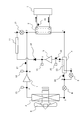
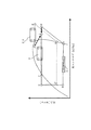
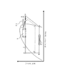
図1乃至図7は実施の形態1を示す図で、図1はヒートポンプ式給湯装置の冷媒回路図、図2は第1の水−冷媒熱交換器2(プレート積層型熱交換器)の内部構成を示す斜視図、図3は冷凍サイクルの動作を示すP−h線図、図4は放熱手段が水―冷媒熱交換器の場合のヒートポンプ式給湯装置の冷媒回路図、図5は放熱手段が水―冷媒熱交換器の場合の冷凍サイクル動作を示すP−h線図、図6は放熱手段が水―冷媒熱交換器の場合の水−冷媒熱交換器内部の温度変化過程を示す図、図7は放熱手段が凍結防止ヒータの場合の冷媒回路構成図、図8は放熱手段が凍結防止ヒータの場合の冷凍サイクル動作を示すP−h線図である。
1 to 7 are
図1により、ヒートポンプ式給湯装置の冷媒回路の一例を説明する。図1に示すヒートポンプ式給湯装置の冷媒回路は、第1の冷凍サイクルと、第2の冷凍サイクルとを備える。 An example of the refrigerant circuit of the heat pump hot water supply apparatus will be described with reference to FIG. The refrigerant circuit of the heat pump hot water supply apparatus shown in FIG. 1 includes a first refrigeration cycle and a second refrigeration cycle.
第1の冷凍サイクルは、主圧縮機1(第1の圧縮機)、第1の水−冷媒熱交換器2(第1の熱交換器)、内部熱交換器3、電動膨張弁4(第1の減圧装置)、外気から採熱する空気熱交換器5(蒸発器)を順次接続して形成されている。 The first refrigeration cycle includes a main compressor 1 (first compressor), a first water-refrigerant heat exchanger 2 (first heat exchanger), an internal heat exchanger 3, and an electric expansion valve 4 (first 1) and an air heat exchanger 5 (evaporator) for collecting heat from outside air are sequentially connected.
第2の冷凍サイクルは、第1の冷凍サイクルの内部熱交換器3と電動膨張弁4との間から分岐し、第1の冷凍サイクルの主圧縮機1と第1の水−冷媒熱交換器2との間に合流する。なお、第2の冷凍サイクルは、第1の水−冷媒熱交換器2と電動膨張弁4との間であれば、他の位置から分岐していてもよい。
The second refrigeration cycle branches from between the internal heat exchanger 3 and the
第2の冷凍サイクルは、第1の冷凍サイクルの内部熱交換器3と電動膨張弁4との間から分岐して、分流膨張弁8(第2の減圧装置)、副圧縮機9の吸入配管22(内部熱交換器3内を貫通する)、副圧縮機9(第2の圧縮機)、逆止弁10、副放熱手段11(放熱手段)、合流膨張弁12(第3の減圧装置)の順に接続されて形成され、第1の冷凍サイクルの主圧縮機1と第1の水−冷媒熱交換器2との間に合流する。
The second refrigeration cycle is branched from between the internal heat exchanger 3 and the
第1の冷凍サイクル、第2の冷凍サイクルには、冷媒として、例えば、R410Aが封入されている。 For example, R410A is enclosed as a refrigerant in the first refrigeration cycle and the second refrigeration cycle.
主圧縮機1には、吸入圧力を検出する圧力センサ13、吐出圧力を検出する圧力センサ14が設けられる。また、副圧縮機9には、吸入圧力を検出する圧力センサ15、吐出圧力を検出する圧力センサ16が設けられる。
The
主圧縮機1の吐出温度を検出する温度センサ17、第1の水−冷媒熱交換器2の出口の給水温度を検出する温度センサ18、副圧縮機9の吸入冷媒の温度を検出する温度センサ19、第1の冷凍サイクルの内部熱交換器3の出口の冷媒の温度を検出する温度センサ20を備える。
A
圧力センサ13〜16、温度センサ17〜20の情報により、図示しない制御部が、ヒートポンプ給湯装置の運転制御を行う。
A control unit (not shown) controls the operation of the heat pump hot water supply device based on information from the
制御部は、所定のプログラムが組み込まれたマイコン(マイクロコンピュータ)で構成される。以下の各種の制御における主語は制御部であるが、一々「制御部が」という文言は記載しない。 The control unit is configured by a microcomputer (microcomputer) in which a predetermined program is incorporated. The subject in the following various controls is the control unit, but the word “control unit” is not described.
空気熱交換器5には、外気からの採熱量を調整する送風機6が設けられている。
The
第1の水−冷媒熱交換器2には、給湯負荷となる給湯タンク7が接続され、熱媒体として水が循環している。図1の矢印は、熱媒体である水の流れを示している。
A hot
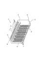
第1の水−冷媒熱交換器2には、公知のプレート積層型熱交換器を使用する。図2により、簡単に第1の水−冷媒熱交換器2(プレート積層型熱交換器)の内部構成を説明する。図2では、外周カバーを構成する筒状体は省略している。第1の水−冷媒熱交換器2(プレート積層型熱交換器)は、一方の最外端のプレート2dに、冷媒配管接続口2aが設けられる。また、他方の最外端のプレート2dに、水配管接続口2bが設けられる。
As the first water-
一対の最外端のプレート2dの間に、複数の波形状の伝熱プレート2cが並べて配置される。伝熱プレート2cの間に、交互に冷媒流路2eと、水流路2fとが形成される。そして、伝熱プレート2cに、各冷媒流路2eと冷媒配管接続口2aとを接続する冷媒連通穴2gが設けられる。また、伝熱プレート2cに、各水流路2fと水配管接続口2bとを接続する水連通穴2hが設けられる。
A plurality of corrugated
このように構成された本実施の形態1のヒートポンプ式給湯装置の動作について説明する。
Operation | movement of the heat pump type hot-water supply apparatus of this
まず、副放熱手段11に何も接続されていない場合における給湯運転の冷凍サイクルの動作について、図1および図3を参照しながら説明する。 First, the operation of the refrigeration cycle in the hot water supply operation when nothing is connected to the auxiliary heat dissipation means 11 will be described with reference to FIGS. 1 and 3.
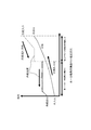
図3は給湯運転時の冷凍サイクルの動作を示すP−h線図(モリエル線図ともいう)で、横軸は比エンタルピ[kJ/kg]、縦軸は冷媒圧力[MPa]である。 FIG. 3 is a Ph diagram (also referred to as a Mollier diagram) showing the operation of the refrigeration cycle during a hot water supply operation. The horizontal axis represents specific enthalpy [kJ / kg], and the vertical axis represents refrigerant pressure [MPa].
図3において、第1の冷凍サイクルは、A→B→C→D→E→Aの実線で示すように動作する。また、第2の冷凍サイクルは、G→H→I→C→D→F→Gの破線で示すように動作する。 In FIG. 3, the first refrigeration cycle operates as indicated by the solid line A → B → C → D → E → A. Further, the second refrigeration cycle operates as indicated by broken lines G → H → I → C → D → F → G.
第1の冷凍サイクルでは、以下に示す動作が行われる。
(1)主圧縮機1に、低圧ガス冷媒(状態A)が吸入される;
(2)低圧ガス冷媒(状態A)が主圧縮機1で圧縮されて高温高圧のガス冷媒(状態B)となり吐出される;
(3)第1の水−冷媒熱交換器2で水に放熱して凝縮し、高圧液冷媒(状態C)になる;
(4)内部熱交換器3で、第2の冷凍サイクルの分岐冷媒と熱交換を行い過冷却液(状態D)になる;
(5)電動膨張弁4で第1の低圧まで減圧され、低圧二相冷媒(状態E)になる;
(6)空気熱交換器5で外気から採熱して蒸発し、再び低圧ガス冷媒(状態A)となる。In the first refrigeration cycle, the following operation is performed.
(1) Low pressure gas refrigerant (state A) is sucked into the
(2) The low-pressure gas refrigerant (state A) is compressed by the
(3) The first water-
(4) The internal heat exchanger 3 exchanges heat with the branched refrigerant of the second refrigeration cycle to become a supercooled liquid (state D);
(5) The
(6) The
電動膨張弁4の開度は、あらかじめ把握している主圧縮機1の運転特性と、圧力センサ13で検知する吸入圧力と、圧力センサ14で検知する吐出圧力との情報から、主圧縮機1に吸入される吸入冷媒(状態A)が、ちょうど飽和蒸気となるような目標吐出温度を予測し、温度センサ17で検知する実際の吐出温度と予測した目標吐出温度とが一致するように調整される。
The opening degree of the
また、主圧縮機1の回転数(運転容量)は、温度センサ18で検知する給水温度が目標値、例えば45℃となるように調整される。このように運転されることで、給湯負荷となる給湯タンク7に所定温度まで昇温した温水を供給する。
Moreover, the rotation speed (operating capacity) of the
しかし、外気温度が極めて低い場合や、要求される加熱能力が大きい場合、主圧縮機1が最大容量で運転しても目標給水温度(例えば45℃)に調整できない場合がある。
However, when the outside air temperature is extremely low or when the required heating capacity is large, even if the
一例では、主圧縮機1に5馬力程度のスクロール圧縮機、副圧縮機9に2馬力程度のロータリ圧縮機が使用される。
In one example, a scroll compressor of about 5 horsepower is used for the
このようなときは、第2の冷凍サイクルが運転される。第2の冷凍サイクルでは、内部熱交換器3出口(状態D)から一部の冷媒を分岐し、分流膨張弁8で第2の低圧(第1の低圧より高い)まで減圧する。この第2の低圧の冷媒(状態F)は、吸入配管22が内部熱交換器3を貫通することにより、内部熱交換器3において高圧液冷媒(状態C)によって加熱され、ガス冷媒(状態G)となって副圧縮機9に吸入される。副圧縮機9で昇圧された第2高圧ガス冷媒(状態H)は、合流膨張弁12で減圧され、主圧縮機1の吐出冷媒(状態B)と合流し、状態Iとなって第1の水−冷媒熱交換器2に流入する。その後、第1の水−冷媒熱交換器2で水に放熱して凝縮し、高圧液冷媒(状態C)になり、内部熱交換器3で、第2の冷凍サイクルの分岐冷媒と熱交換を行い過冷却液(状態D)になる。
In such a case, the second refrigeration cycle is operated. In the second refrigeration cycle, a part of the refrigerant is branched from the outlet of the internal heat exchanger 3 (state D), and the pressure is reduced to the second low pressure (higher than the first low pressure) by the
分流膨張弁8の開度は、温度センサ19及び圧力センサ15で検知される副圧縮機9の吸入冷媒(状態G)の状態が、飽和蒸気か、あるいは僅かに過熱する程度になるように調整される。
The opening degree of the
副圧縮機9は一定速圧縮機でもよいが、インバータで駆動される回転数調整可能な圧縮機である場合は、圧力センサ15で検知される吸入圧力が所定値となるように、副圧縮機9の回転数が調整される。
The sub-compressor 9 may be a constant speed compressor. However, when the
合流膨張弁12の開度は、圧力センサ16で検知される副圧縮機9の吐出圧力を操作できるので、副圧縮機9の入力が要求される加熱能力を満たすような吐出圧力になるように調整する。
Since the opening of the merging
本実施の形態1のヒートポンプ式給湯装置は、このように加熱能力が最大になるよう第2の冷凍サイクルが運転されることで、第1の水−冷媒熱交換器2で水に放熱して凝縮した高圧液冷媒(状態C)が、内部熱交換器3で第2の冷凍サイクルの分岐冷媒と熱交換を行い過冷却液(状態D)になり、状態Eと状態Aとの差が拡大するので、外気からの採熱量が増大し、加熱運転の運転効率が向上する。
The heat pump type hot water supply apparatus of the first embodiment dissipates heat to the water in the first water-
また、外気からの採熱量と主圧縮機1の入力に加え、副圧縮機9の入力も全体の凝縮熱量に加わり、最大加熱能力が増大する。
Further, in addition to the amount of heat collected from the outside air and the input of the
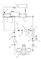
続いて、副放熱手段11が第2の水−冷媒熱交換器23(第2の熱交換器)となる場合について、図4乃至図6を参照しながら説明する。 Next, the case where the auxiliary heat radiating means 11 is the second water-refrigerant heat exchanger 23 (second heat exchanger) will be described with reference to FIGS. 4 to 6.
基本的な冷凍サイクルの動作および運転制御は、前述した副放熱手段11に何も接続されていない場合と同様であるが、ここでは、副放熱手段11が第2の水−冷媒熱交換器23であり、給湯タンク7からの循環水は、第1の冷凍サイクル側の第1の水−冷媒熱交換器2を経由して第2の水−冷媒熱交換器23に通水される。
The basic refrigeration cycle operation and operation control are the same as in the case where nothing is connected to the sub-heat dissipating means 11 described above, but here, the sub-heat dissipating means 11 is the second water-
副圧縮機9から吐出された高温高圧のガス冷媒(状態H)は第2の水−冷媒熱交換器23で水を再度加熱し、循環水はより高温となって給湯タンク7に戻る。第2の水−冷媒熱交換器23を出た冷媒(状態J)は合流膨張弁12で減圧され、主圧縮機1の吐出冷媒(状態B)と合流し(状態I)、その後第1の水−冷媒熱交換器2に流通する。
The high-temperature and high-pressure gas refrigerant (state H) discharged from the sub-compressor 9 heats the water again in the second water-
この第2の冷凍サイクルが運転される状況においては、主圧縮機1は既に最大容量運転を行っている。また、合流膨張弁12では、50℃以上の高温水が要求された場合などにおいて、その水温での出湯が可能となる目標吐出圧力を設定し、副圧縮機9の吐出圧力が設定した目標吐出圧力になるように開度調整される。副圧縮機9では、温度センサ18で検知される目標出湯温度が実現できる加熱能力となるように回転数が調整される。
また、副圧縮機9の吐出圧力(圧力センサ16出力値)は、第1の水−冷媒熱交換器2から第2の水−冷媒熱交換器23に流入する水温によってほぼ決まってしまう。そこで、合流膨張弁12は第2の水−冷媒熱交換器23出口(状態J)の過冷却度が1〜2[K]となるように開度調整されるとしてもよい。この場合、副圧縮機9の回転数によって吸入圧力(圧力センサ15出力値)および副圧縮機9の入力が変化する。したがって、第2の水−冷媒熱交換器23での加熱能力も副圧縮機9の回転数に伴って変化するので、出口水温が設定値となるように制御できる。In the situation where the second refrigeration cycle is operated, the
Further, the discharge pressure of the sub-compressor 9 (the output value of the pressure sensor 16) is substantially determined by the water temperature flowing from the first water-
図6は第1の水−冷媒熱交換器2、第2の水−冷媒熱交換器23内部における水と冷媒との温度変化の過程を示している。循環水側は第1の水−冷媒熱交換器2、第2の水−冷媒熱交換器23を直列に流通し、入口から出口までほぼ直線的に温度上昇する。
FIG. 6 shows a process of temperature change between water and refrigerant in the first water-
一方、冷媒側では、第2の水−冷媒熱交換器23の凝縮圧力は第1の水−冷媒熱交換器2のそれより高く設定され、それぞれ異なる凝縮温度となっているので、1つの凝縮温度で昇温する場合よりも、上昇していく水温に対して冷媒との温度差を小さくできる。
On the other hand, on the refrigerant side, the condensing pressure of the second water-
つまり、水温が低い側では低めの凝縮温度で昇温し、水温が高い側では高めの凝縮温度で昇温できるので、水と冷媒の温度差が必要以上に大きくなることがない。よって、同一出湯温度に対して高効率で昇温することができ、冷凍サイクルの成績係数(COP)を向上することができる。 That is, the temperature can be raised at a lower condensing temperature on the low water temperature side, and the temperature can be raised at a higher condensing temperature on the high water temperature side, so that the temperature difference between water and the refrigerant does not become larger than necessary. Therefore, the temperature can be raised with high efficiency with respect to the same hot water temperature, and the coefficient of performance (COP) of the refrigeration cycle can be improved.
特に50℃以上の高温水が要求されたとき、凝縮温度はそれ以上のレベルに設定する必要があるが、副放熱手段11が第2の水−冷媒熱交換器23となる図4の冷媒回路では、第2の水−冷媒熱交換器23側、すなわち第2の冷凍サイクル側だけをその高凝縮温度にすればよく、システム全体として高効率で運転できるとともに、第2の冷凍サイクルでは外気から採熱する必要がないので、第2の冷凍サイクルでは低圧を比較的高い状態で運転できる。よって、外気が極めて低い場合でも高圧縮比になりにくく、吐出温度異常上昇などの運転制限が発生しにくい。すなわち、第2の冷凍サイクルの低圧を第1の冷凍サイクルの低圧よりも高い状態に制御することで厳しい運転条件においても信頼性を向上することができる。
In particular, when high-temperature water of 50 ° C. or higher is required, the condensation temperature needs to be set to a level higher than that, but the sub-heat dissipating means 11 serves as the second water-
さらに、第1の水−冷媒熱交換器2では、主圧縮機1で循環される冷媒と副圧縮機9で循環される冷媒が合流して流通する。
Further, in the first water-
一般に水−冷媒熱交換器として使用されるプレート積層型熱交換器(図2)は、水側と冷媒側の流路が等しいので冷媒側の流速が遅くなることが多く、それに伴い冷媒側伝熱性能が低下しやすいが、本実施の形態においては、第1の水−冷媒熱交換器2を流通する冷媒流量が、主圧縮機1と副圧縮機9の合計となり冷媒流速が速くなるので、この第1の水−冷媒熱交換器2の伝熱性能が向上するという効果を有する。
また、プレート積層型熱交換器は過冷却液部分で特に流速が低下して伝熱特性が悪化するため、過冷却度を大きくとることができない。しかし、この実施の形態では内部熱交換器で大きな過冷却度をとることができ、プレート積層型熱交換器を用いる場合でも過冷却度が大きい高効率な冷凍サイクル運転が可能となる。In general, a plate-stacked heat exchanger (FIG. 2) used as a water-refrigerant heat exchanger has a slow flow rate on the refrigerant side because the flow paths on the water side and the refrigerant side are the same, and accordingly, the refrigerant side transmission is reduced. Although the thermal performance is likely to deteriorate, in the present embodiment, the flow rate of the refrigerant flowing through the first water-
In addition, the plate-stacked heat exchanger cannot reduce the degree of supercooling because the flow rate is lowered particularly in the supercooled liquid portion and the heat transfer characteristics deteriorate. However, in this embodiment, a large degree of supercooling can be achieved with the internal heat exchanger, and even when a plate stacked heat exchanger is used, a highly efficient refrigeration cycle operation with a large degree of supercooling is possible.
続いて、副放熱手段11を凍結防止ヒータとして用いる場合について、図7、図8を参照しながら説明する。 Next, the case where the auxiliary heat radiating means 11 is used as a freeze prevention heater will be described with reference to FIGS.
給湯運転において外気が氷点下になる状況では空気熱交換器5に着霜が生じるため、これを融かすための除霜運転が間欠的に行われるが、除霜時に生じたドレンや融け残った霜が空気熱交換器5の下部や、ドレン受け皿21に蓄積されて氷が成長し、給湯装置自体が破損してしまうことがある。これを回避するため、図7では、空気熱交換器5下部の伝熱管の一部を流用、あるいは空気熱交換器5の下方に配置されるドレン受け皿21に密着させた配管を設置し、副放熱手段11としている。
In the situation where the outside air is below freezing in the hot water supply operation, frost formation occurs in the
図7の冷媒回路における第2の冷凍サイクルによる凍結防止運転も、図8のP−h線図に示すように、基本的な動作は前述の図4の冷媒回路と同様である。 The antifreezing operation by the second refrigeration cycle in the refrigerant circuit of FIG. 7 is basically the same as the refrigerant circuit of FIG. 4 as shown in the Ph diagram of FIG.
副圧縮機9が稼動すると、内部熱交換器3で熱回収され、副放熱手段11である凍結防止ヒータ24に副圧縮機9から吐出された高温高圧のガス冷媒が流通し、融け残った霜や再凍結した氷を融解させる。この凍結防止運転は、給湯運転中に常に運転されるか、あるいは除霜運転終了後、所定時間だけ運転される。
When the sub-compressor 9 is operated, heat is recovered by the internal heat exchanger 3, and the high-temperature and high-pressure gas refrigerant discharged from the
一般的に寒冷地仕様とされるヒートポンプ装置には凍結防止ヒータとして電気ヒータが装備されるが、本実施の形態によれば、副圧縮機9の電気入力に加えて、蒸発器エンタルピ差拡大により外気採熱量も増えるため、電気入力を超える凝縮熱量が得られ、高効率な凍結防止運転を行うことができる。 In general, heat pump devices that are designed for cold regions are equipped with electric heaters as anti-freezing heaters. However, according to the present embodiment, in addition to the electric input of the sub-compressor 9, the difference in the evaporator enthalpy difference is increased. Since the amount of heat collected from the outside air also increases, a heat of condensation exceeding the electric input can be obtained, and a highly efficient antifreezing operation can be performed.
以上のように、この実施の形態に係るヒートポンプ式給湯装置は、副圧縮機9と内部熱交換器3による熱回収作用によって蒸発器エンタルピ差を拡大するので、副圧縮機9の電気入力以上の大きな過熱能力が得られるとともに、外気からの採熱量が増えることにより電気ヒータによる加熱能力増大作用よりもCOPが高い給湯運転を行うことができる。
As described above, the heat pump type hot water supply apparatus according to this embodiment expands the enthalpy difference of the evaporator by the heat recovery action of the
また、第1の水−冷媒熱交換器2に流通する冷媒流量が主圧縮機1と副圧縮機9の合計となり冷媒流速が速くなるので、第1の水−冷媒熱交換器2内部の冷媒側伝熱性能が向上する。これは、第1の水−冷媒熱交換器2がプレート積層型熱交換器である場合に特に効果がある。
In addition, since the refrigerant flow rate flowing through the first water-
また、第2の冷凍サイクル側に電気ヒータ代替となる副放熱手段11である凍結防止ヒータ24を配置し、水加熱や空気熱交換器5の凍結防止に利用するようにしたので、内部熱交換器3での熱回収作用が冷凍サイクルのCOPを向上し、電気ヒータを利用するものよりも高効率となる給湯運転を行うことができる。
In addition, since the
また、この実施の形態に係るヒートポンプ式給湯装置は、副圧縮機9と合流膨張弁12との間に第2の水−冷媒熱交換器23を備え、第1の冷凍サイクルと第2の冷凍サイクルとで異なる凝縮温度を生成するようにし、2段階で水を加熱するように配置したので、高温水を要求されたときでも高効率でかつ信頼性の高い加熱運転を行うことができる。
Moreover, the heat pump type hot water supply apparatus according to this embodiment includes a second water-
以上の説明では、第2の冷凍サイクルの副圧縮機9と合流膨張弁12との間に設ける副放熱手段11に、第2の水−冷媒熱交換器23又は凍結防止ヒータ24を単独に接続するものであった。しかし、複数の副放熱手段11を並列に配置して、第2の冷凍サイクルを流れる冷媒を複数の副放熱手段11のいずれへ流すかを切り替える副放熱手段切替装置(放熱手段切替装置)を設けるようにしてもよい。
In the above description, the second water-
また、以上の説明では、ヒートポンプ装置の一例として、温めた水(温水)を給湯タンク7へ供給するヒートポンプ式給湯装置を一例として説明した。しかし、ヒートポンプ装置は、温めた水をラジエータ等へ供給するヒートポンプ式暖房装置であってもよい。
また、上記説明では、第1の水−冷媒熱交換器2や第2の水−冷媒熱交換器23で冷媒と熱交換される熱媒体の一例として水を用いて説明した。しかし、第1の水−冷媒熱交換器2や第2の水−冷媒熱交換器23で冷媒と熱交換される熱媒体は、水以外の流体であっても構わない。例えば、第1の水−冷媒熱交換器2や第2の水−冷媒熱交換器23の代わりに、空気と冷媒とを熱交換する空気熱交換器を用いていもよい。空気熱交換器を用いた場合、温風乾燥装置等、高温の空気が必要となる装置で特に効果を発揮する。Moreover, in the above description, the heat pump type hot water supply apparatus which supplies warm water (hot water) to the hot
Moreover, in the said description, it demonstrated using water as an example of the heat medium heat-exchanged with a refrigerant | coolant in the 1st water-
1 主圧縮機、2 第1の水−冷媒熱交換器、3 内部熱交換器、4 電動膨張弁、5 空気熱交換器、6 送風機、7 給湯タンク、8 分流膨張弁、9 副圧縮機、10 逆止弁、11 副放熱手段、12 合流膨張弁、13 圧力センサ、14 圧力センサ、15 圧力センサ、16 圧力センサ、17 温度センサ、18 温度センサ、19 温度センサ、20 温度センサ、21 ドレン受け皿、22 吸入配管、23 第2の水−冷媒熱交換器、24 凍結防止ヒータ。
DESCRIPTION OF
Claims (9)
前記第1の熱交換器と前記第1の減圧装置との間から分岐し、第2の減圧装置、前記内部熱交換器、第2の圧縮機、第3の減圧装置が順次接続され、前記第1の圧縮機と前記第1の熱交換器との間に再び合流する第2の冷凍サイクルと
を備えたことを特徴とするヒートポンプ装置。A first refrigeration cycle configured by sequentially connecting a first compressor, a first heat exchanger, an internal heat exchanger, a first decompression device, and an evaporator;
Branching from between the first heat exchanger and the first pressure reducing device, a second pressure reducing device, the internal heat exchanger, a second compressor, a third pressure reducing device are sequentially connected, A heat pump apparatus comprising: a second refrigeration cycle that rejoins between the first compressor and the first heat exchanger.
ことを特徴とする請求項2に記載のヒートポンプ装置。The heat dissipating means is a second heat exchanger, and the fluid after heat exchange with the refrigerant flowing through the first refrigeration cycle in the first heat exchanger flows to the second heat exchanger. The heat pump device according to claim 2, wherein the heat pump device is provided so as to exchange heat with the refrigerant flowing through the second refrigeration cycle in the second heat exchanger.
前記第2の熱交換器の凝縮圧力が、前記第1の熱交換器の凝縮圧力よりも高くなるように前記第3の減圧装置の開度を調整する制御部
を備えることを特徴とする請求項3に記載のヒートポンプ装置。The heat pump device further includes:
The control part which adjusts the opening degree of a said 3rd decompression device so that the condensation pressure of a said 2nd heat exchanger may become higher than the condensation pressure of a said 1st heat exchanger, It is characterized by the above-mentioned. Item 4. The heat pump device according to Item 3.
ことを特徴とする請求項4に記載のヒートポンプ装置。The said control part controls the said 2nd compressor so that the evaporation pressure in a said 2nd refrigerating cycle becomes higher than the evaporating pressure in a said 1st refrigerating cycle, It is characterized by the above-mentioned. Heat pump device.
前記第2の熱交換器は、水と、前記第2の冷凍サイクルを流れる冷媒とを熱交換する水−冷媒熱交換器である
ことを特徴とする請求項3から5までのいずれかに記載のヒートポンプ装置。The first heat exchanger is a water-refrigerant heat exchanger that exchanges heat between water and a refrigerant flowing through the first refrigeration cycle.
The said 2nd heat exchanger is a water-refrigerant heat exchanger which heat-exchanges water and the refrigerant | coolant which flows through a said 2nd refrigerating cycle, The any one of Claim 3-5 characterized by the above-mentioned. Heat pump device.
ことを特徴とする請求項6に記載のヒートポンプ装置。The heat pump device according to claim 6, wherein at least one of the first heat exchanger and the second heat exchanger is a plate stacked heat exchanger.
ことを特徴とする請求項2に記載のヒートポンプ装置。3. The heat pump apparatus according to claim 2, wherein the heat dissipating means is constituted by a pipe disposed in the vicinity of the lower end of the evaporator.
前記第2の冷凍回路を流れる冷媒を前記複数の放熱手段のいずれへ流すかを切り替える放熱手段切替装置と
を備えたことを特徴とする請求項1に記載のヒートポンプ装置。The second refrigeration cycle further includes a plurality of heat dissipating means arranged in parallel between the second compressor and the third pressure reducing device,
The heat pump device according to claim 1, further comprising: a heat dissipating means switching device that switches which of the plurality of heat dissipating means flows the refrigerant flowing through the second refrigeration circuit.
Priority Applications (1)
| Application Number | Priority Date | Filing Date | Title |
|---|---|---|---|
| JP2011515942A JP5111663B2 (en) | 2009-05-26 | 2010-03-30 | Heat pump equipment |
Applications Claiming Priority (4)
| Application Number | Priority Date | Filing Date | Title |
|---|---|---|---|
| PCT/JP2009/059622 WO2010137120A1 (en) | 2009-05-26 | 2009-05-26 | Heat pump type hot water supply device |
| JPPCT/JP2009/059622 | 2009-05-26 | ||
| JP2011515942A JP5111663B2 (en) | 2009-05-26 | 2010-03-30 | Heat pump equipment |
| PCT/JP2010/055686 WO2010137401A1 (en) | 2009-05-26 | 2010-03-30 | Heat pump device |
Publications (2)
| Publication Number | Publication Date |
|---|---|
| JPWO2010137401A1 JPWO2010137401A1 (en) | 2012-11-12 |
| JP5111663B2 true JP5111663B2 (en) | 2013-01-09 |
Family
ID=47676518
Family Applications (1)
| Application Number | Title | Priority Date | Filing Date |
|---|---|---|---|
| JP2011515942A Expired - Fee Related JP5111663B2 (en) | 2009-05-26 | 2010-03-30 | Heat pump equipment |
Country Status (1)
| Country | Link |
|---|---|
| JP (1) | JP5111663B2 (en) |
Citations (4)
| Publication number | Priority date | Publication date | Assignee | Title |
|---|---|---|---|---|
| JP2000329416A (en) * | 1999-03-15 | 2000-11-30 | Denso Corp | Refrigeration cycle |
| JP2005061784A (en) * | 2003-08-20 | 2005-03-10 | Yanmar Co Ltd | Engine heat pump |
| US20070017240A1 (en) * | 2005-07-19 | 2007-01-25 | Hussmann Corporation | Refrigeration system with mechanical subcooling |
| WO2007142619A2 (en) * | 2006-06-01 | 2007-12-13 | Carrier Corporation | Multi-stage compressor unit for a refrigeration system |
-
2010
- 2010-03-30 JP JP2011515942A patent/JP5111663B2/en not_active Expired - Fee Related
Patent Citations (4)
| Publication number | Priority date | Publication date | Assignee | Title |
|---|---|---|---|---|
| JP2000329416A (en) * | 1999-03-15 | 2000-11-30 | Denso Corp | Refrigeration cycle |
| JP2005061784A (en) * | 2003-08-20 | 2005-03-10 | Yanmar Co Ltd | Engine heat pump |
| US20070017240A1 (en) * | 2005-07-19 | 2007-01-25 | Hussmann Corporation | Refrigeration system with mechanical subcooling |
| WO2007142619A2 (en) * | 2006-06-01 | 2007-12-13 | Carrier Corporation | Multi-stage compressor unit for a refrigeration system |
Also Published As
| Publication number | Publication date |
|---|---|
| JPWO2010137401A1 (en) | 2012-11-12 |
Similar Documents
| Publication | Publication Date | Title |
|---|---|---|
| WO2010137401A1 (en) | Heat pump device | |
| KR102471584B1 (en) | Phase Change Material-Based Enhancement Method for Reverse-Cycle Defrosting of Vapor Compression Refrigeration Systems | |
| JP5868498B2 (en) | Heat pump equipment | |
| JP5327308B2 (en) | Hot water supply air conditioning system | |
| JP5595140B2 (en) | Heat pump type hot water supply / air conditioner | |
| JP5094942B2 (en) | Heat pump equipment | |
| EP2924375B1 (en) | Refrigeration cycle device and hot water generation device provided therewith | |
| JPWO2011092802A1 (en) | Heat pump device and refrigerant bypass method | |
| JP2010276230A (en) | Refrigerating device | |
| EP2765370A1 (en) | Refrigeration cycle apparatus and hot water generator provided with the same | |
| JPWO2018025318A1 (en) | Heat pump equipment | |
| WO2010143373A1 (en) | Heat pump system | |
| CN102032699A (en) | Refrigeration cycle apparatus and hot water heater | |
| KR101619016B1 (en) | Refrigeration apparatus having defrosting cycle by hot gas | |
| JP2011179697A (en) | Refrigerating cycle device and water heating/cooling device | |
| JP2014105890A (en) | Refrigeration cycle device and hot-water generating device including the same | |
| JP2015068564A (en) | Heat pump system and heat pump type water heater | |
| EP2918921B1 (en) | Hot water generator | |
| CN103776185B (en) | Heat pump assembly | |
| JP2014134316A (en) | Refrigeration unit | |
| JP5111663B2 (en) | Heat pump equipment | |
| KR20140097858A (en) | Heat pump | |
| JP2014031930A (en) | Refrigeration cycle device | |
| KR102258449B1 (en) | Hybrid heat pump system | |
| KR102165353B1 (en) | Refrigerant system |
Legal Events
| Date | Code | Title | Description |
|---|---|---|---|
| TRDD | Decision of grant or rejection written | ||
| A01 | Written decision to grant a patent or to grant a registration (utility model) |
Free format text: JAPANESE INTERMEDIATE CODE: A01 Effective date: 20120911 |
|
| A01 | Written decision to grant a patent or to grant a registration (utility model) |
Free format text: JAPANESE INTERMEDIATE CODE: A01 |
|
| A61 | First payment of annual fees (during grant procedure) |
Free format text: JAPANESE INTERMEDIATE CODE: A61 Effective date: 20121009 |
|
| FPAY | Renewal fee payment (event date is renewal date of database) |
Free format text: PAYMENT UNTIL: 20151019 Year of fee payment: 3 |
|
| R150 | Certificate of patent or registration of utility model |
Ref document number: 5111663 Country of ref document: JP Free format text: JAPANESE INTERMEDIATE CODE: R150 Free format text: JAPANESE INTERMEDIATE CODE: R150 |
|
| R250 | Receipt of annual fees |
Free format text: JAPANESE INTERMEDIATE CODE: R250 |
|
| R250 | Receipt of annual fees |
Free format text: JAPANESE INTERMEDIATE CODE: R250 |
|
| R250 | Receipt of annual fees |
Free format text: JAPANESE INTERMEDIATE CODE: R250 |
|
| R250 | Receipt of annual fees |
Free format text: JAPANESE INTERMEDIATE CODE: R250 |
|
| R250 | Receipt of annual fees |
Free format text: JAPANESE INTERMEDIATE CODE: R250 |
|
| R250 | Receipt of annual fees |
Free format text: JAPANESE INTERMEDIATE CODE: R250 |
|
| R250 | Receipt of annual fees |
Free format text: JAPANESE INTERMEDIATE CODE: R250 |
|
| R250 | Receipt of annual fees |
Free format text: JAPANESE INTERMEDIATE CODE: R250 |
|
| R250 | Receipt of annual fees |
Free format text: JAPANESE INTERMEDIATE CODE: R250 |
|
| LAPS | Cancellation because of no payment of annual fees |