JP5111641B2 - Game machine - Google Patents

Game machine Download PDF

Info

Publication number
JP5111641B2
JP5111641B2 JP2011097530A JP2011097530A JP5111641B2 JP 5111641 B2 JP5111641 B2 JP 5111641B2 JP 2011097530 A JP2011097530 A JP 2011097530A JP 2011097530 A JP2011097530 A JP 2011097530A JP 5111641 B2 JP5111641 B2 JP 5111641B2
Authority
JP
Japan
Prior art keywords
ball
light emitting
game
game ball
posture
Prior art date
Legal status (The legal status is an assumption and is not a legal conclusion. Google has not performed a legal analysis and makes no representation as to the accuracy of the status listed.)
Active
Application number
JP2011097530A
Other languages
Japanese (ja)
Other versions
JP2012228322A (en
Inventor
尋康 伊藤
Current Assignee (The listed assignees may be inaccurate. Google has not performed a legal analysis and makes no representation or warranty as to the accuracy of the list.)
Kyoraku Industrial Co Ltd
Original Assignee
Kyoraku Industrial Co Ltd
Priority date (The priority date is an assumption and is not a legal conclusion. Google has not performed a legal analysis and makes no representation as to the accuracy of the date listed.)
Filing date
Publication date
Application filed by Kyoraku Industrial Co Ltd filed Critical Kyoraku Industrial Co Ltd
Priority to JP2011097530A priority Critical patent/JP5111641B2/en
Publication of JP2012228322A publication Critical patent/JP2012228322A/en
Application granted granted Critical
Publication of JP5111641B2 publication Critical patent/JP5111641B2/en
Active legal-status Critical Current
Anticipated expiration legal-status Critical

Links

Images

Description

本発明は、パチンコ遊技機等の遊技機に関する。   The present invention relates to a gaming machine such as a pachinko gaming machine.

従来、パチンコ遊技機等の遊技機では、当該遊技機の遊技盤上に円弧状に湾曲させた内レールおよび外レールが固設され、当該内レールおよび外レールの間に形成された発射球通路を通って、当該遊技機の遊技領域へ遊技球が発射される。そして、内レールの上端には、遊技領域へ打ち出された遊技球が発射球通路へ戻ることを防止するために、球戻り防止機構が設けられている(例えば、特許文献1参照)。   Conventionally, in a gaming machine such as a pachinko gaming machine, an inner rail and an outer rail that are curved in an arc shape are fixed on a gaming board of the gaming machine, and a launching ball passage formed between the inner rail and the outer rail A game ball is launched through the game area of the gaming machine. A ball return prevention mechanism is provided at the upper end of the inner rail in order to prevent the game ball launched into the game area from returning to the launch ball passage (see, for example, Patent Document 1).

特開2006−158454号公報JP 2006-158454 A

ところで、従来の遊技機において、釣り糸やピアノ線等の細線の先端に遊技球を接着し、当該遊技球を遊技領域へ発射して遊技することによって不正な賞球や当たりを発生させる行為が行われている。具体的には、上記不正を行う遊技者は、上記細線を接着した遊技球を遊技領域へ発射し、遊技機に設けられた始動口や普通入賞口へ当該遊技球を入賞させる。そして、当該入賞状態が連続して発生するように細線を出し入れして始動口や普通入賞口の内部で遊技球を往復移動させることによって、賞球や当たり抽選を連続的に発生させる。   By the way, in a conventional gaming machine, an act of generating an illegal prize ball or winning is performed by attaching a game ball to the tip of a thin line such as a fishing line or a piano wire and launching the game ball into the game area to play. It has been broken. Specifically, a player who performs the fraud launches a game ball to which the fine line is bonded to a game area, and wins the game ball in a starting port or a normal winning port provided in the gaming machine. Then, a winning ball and a winning lottery are continuously generated by inserting / removing a thin line so that the winning state is continuously generated and reciprocating the game ball inside the start opening or the normal winning opening.

しかしながら、上記のような細線としては視認され難い細線が用いられることが多い。そのため、上記の球戻り防止機構を備えた遊技機では、細線を接着した遊技球を用いた不正をパチンコホールの店員が発見することが容易ではなかった。   However, a thin line that is difficult to be visually recognized is often used as the thin line as described above. Therefore, in the gaming machine equipped with the above-described ball return prevention mechanism, it is not easy for a pachinko hall clerk to find fraud using a gaming ball to which a thin wire is bonded.

それ故に、本発明の目的は、細線を接着した遊技球を用いた不正を容易に発見することが可能な遊技機を提供することである。   Therefore, an object of the present invention is to provide a gaming machine that can easily detect fraud using a gaming ball to which a thin wire is bonded.

上記目的を達成するために、本発明は例えば以下のような構成を採用し得る。なお、特許請求の範囲の記載を解釈する際に、特許請求の範囲の記載によってのみその範囲が解釈されるべきであることが理解され、特許請求の範囲の記載と本欄の記載とが矛盾する場合には、特許請求の範囲の記載が優先する。なお、括弧内の参照符号等は、本発明の理解を助けるために後述する実施形態との対応関係を示したものであって、本発明の範囲を何ら限定するものではない。   In order to achieve the above object, the present invention may employ the following configuration, for example. When interpreting the description of the claims, it is understood that the scope should be interpreted only by the description of the claims, and the description of the claims and the description in this column are contradictory. In that case, priority is given to the claims. Note that reference numerals and the like in parentheses indicate correspondence with embodiments described later to help understanding of the present invention, and do not limit the scope of the present invention.

本発明の遊技機(1)の一構成例は、遊技盤(2)の前面に設けられた発射球通路(63)の内側に固設される内レール(61)の上側端部または当該上側端部の近傍に設けられ、発射球通路から進入した遊技球と接触可能な第1の姿勢と、遊技球の接触により一時的に変化する姿勢であって当該第1の姿勢とは異なる姿勢である第2の姿勢とに姿勢変化可能な回動部材(7,73)と、回動部材の後方に埋設される発光部(90)とを備える。そして、発光部は、回動部材が第1の姿勢および第2の姿勢のいずれか一方の姿勢のときにのみ遊技盤の正面から視認できるような位置に埋設される。   One configuration example of the gaming machine (1) of the present invention is the upper end of the inner rail (61) fixed on the inner side of the launch ball passage (63) provided on the front surface of the gaming board (2) or the upper side. A first posture that is provided in the vicinity of the end portion and is capable of contacting a game ball that has entered from the launch ball passage, and a posture that temporarily changes due to the contact of the game ball, and is different from the first posture. A rotating member (7, 73) capable of changing its attitude to a second attitude and a light emitting unit (90) embedded behind the rotating member are provided. The light emitting unit is embedded at a position that can be viewed from the front of the game board only when the rotating member is in one of the first posture and the second posture.

また、上記発光部は、遊技機が動作している間は常時発光状態であってもよい。   The light emitting unit may be always in a light emitting state while the gaming machine is operating.

また、上記発光部は、回動部材の姿勢が当該発光部を視認できない姿勢のとき、当該回動部材の一部に隠されて視認できないような位置に埋設されてもよい。   Further, the light emitting unit may be embedded at a position where the rotating member is hidden by a part of the rotating member and cannot be visually recognized when the rotating member is in a position where the light emitting unit cannot be viewed.

また、上記回動部材は、第1の姿勢においては発射球通路側へ起立した姿勢となるとともに、第2の姿勢においては発射球通路から退避する方向へ傾倒する球止め片(735)を有する球戻り防止部材であってもよい。   In addition, the rotating member has a ball-stopping piece (735) that is tilted in a direction of retreating from the shooting ball passage in the second posture while being in a posture standing on the shooting ball passage side in the first posture. A ball return prevention member may be used.

本発明によれば、細線を接着した遊技球を用いた不正が行われていることを容易に発見することができる。   According to the present invention, it is possible to easily find out that fraud using a game ball to which a thin wire is bonded is being performed.

本発明の一実施形態に係る遊技機1の一例を示す概略正面図Schematic front view showing an example of a gaming machine 1 according to an embodiment of the present invention 発射球通路63および球戻り防止装置7を通って遊技領域20へ発射される遊技球の動きの一例を説明するための概要図Schematic diagram for explaining an example of the movement of a game ball that is launched into the game area 20 through the launch ball passage 63 and the ball return prevention device 7 球戻り防止装置7を内レール61に取り付けた状態を上側から見た一例を示す図The figure which shows an example which looked at the state which attached the ball | bowl return prevention apparatus 7 to the inner rail 61 from the upper side 球戻り防止装置7を内レール61に取り付けた状態を下側から見た一例を示す図The figure which shows an example which looked at the state which attached the ball | bowl return prevention apparatus 7 to the inner rail 61 from the lower side 球戻り防止装置7を内レール61に取り付けた状態を側方から見た一例を示す、図3のC−C線断面図3 is a cross-sectional view taken along the line CC of FIG. 球戻り防止装置7の内部構造の一例を示す分解斜視図An exploded perspective view showing an example of the internal structure of the ball return prevention device 7 傾動部材73と発光素子90の位置関係を説明するための図The figure for demonstrating the positional relationship of the tilting member 73 and the light emitting element 90. FIG. 傾動部材73と発光素子90の位置関係を説明するための図The figure for demonstrating the positional relationship of the tilting member 73 and the light emitting element 90. FIG. 遊技球が発射された際の球戻り防止装置7の状態の一例を示す球戻り防止装置7の要部断面図Cross-sectional view of the main part of the ball return prevention device 7 showing an example of the state of the ball return prevention device 7 when the game ball is launched 細線を接着した遊技球を用いた不正が球戻り防止装置7によって防止された一例を示す球戻り防止装置7の要部断面図Cross-sectional view of the main part of the ball return prevention device 7 showing an example in which fraud using the game ball bonded with a thin wire is prevented by the ball return prevention device 7 傾動部材73と発光素子90の位置関係を説明するための図The figure for demonstrating the positional relationship of the tilting member 73 and the light emitting element 90. FIG. 傾動部材73と発光素子90の位置関係を説明するための図The figure for demonstrating the positional relationship of the tilting member 73 and the light emitting element 90. FIG. 傾動部材73と発光素子90の位置関係を説明するための図The figure for demonstrating the positional relationship of the tilting member 73 and the light emitting element 90. FIG. 傾動部材73と発光素子90の位置関係を説明するための図The figure for demonstrating the positional relationship of the tilting member 73 and the light emitting element 90. FIG. 傾動部材73を役物として配置した場合の例Example when the tilting member 73 is arranged as an accessory

以下、図1および図2を参照して、本発明の一実施形態に係る球戻り防止装置が搭載された遊技機について説明する。なお、図1は、本発明の一実施形態に係る球戻り防止装置7が搭載された遊技機1の一例を示す概略正面図である。図2は、発射球通路63および球戻り防止装置7を通って遊技領域20へ発射される遊技球の動きの一例を説明するための概要図である。   Hereinafter, with reference to FIG. 1 and FIG. 2, a gaming machine equipped with a ball return prevention device according to an embodiment of the present invention will be described. FIG. 1 is a schematic front view showing an example of a gaming machine 1 equipped with a ball return prevention device 7 according to an embodiment of the present invention. FIG. 2 is a schematic diagram for explaining an example of the movement of a game ball that is launched into the game area 20 through the launch ball passage 63 and the ball return prevention device 7.

図1において、遊技機1は、例えば遊技者の指示操作により打ち出された遊技球が入賞すると賞球を払い出すように構成されたパチンコ遊技機である。この遊技機1は、遊技球が打ち出される遊技盤2と、遊技盤2を囲む枠部材5とを備えている。枠部材5は、軸支側に設けられた蝶番を中心に、遊技機1の主部に対して開閉可能に構成され、遊技盤2に対して着脱自在に取り付けられている。そして、枠部材5の前面側となる所定位置(例えば、軸支側とは反対側となる端部)には錠部43が設けられており、錠部43を開錠することによって枠部材5を開くことが可能となる。このように、枠部材5を開くことによって遊技盤2が外部に開放した状態となり、遊技機1が設置されている店の従業員が遊技機1の前面から遊技盤2を直接触るような作業が可能となる。   In FIG. 1, a gaming machine 1 is a pachinko gaming machine configured to pay out a winning ball when a gaming ball launched by an instruction operation by a player wins a prize, for example. This gaming machine 1 includes a game board 2 on which game balls are launched, and a frame member 5 surrounding the game board 2. The frame member 5 is configured to be openable and closable with respect to the main part of the gaming machine 1 around a hinge provided on the shaft support side, and is detachably attached to the game board 2. And the lock part 43 is provided in the predetermined position (for example, edge part on the opposite side to a shaft support side) which becomes the front side of the frame member 5, and the frame member 5 is unlocked by unlocking the lock part 43. Can be opened. In this way, the game board 2 is opened to the outside by opening the frame member 5, and the employee of the store where the game machine 1 is installed directly contacts the game board 2 from the front of the game machine 1. Is possible.

遊技盤2は、その前面に、遊技球により遊技を行うための遊技領域20が形成されている。また、遊技盤2には、下方(発射装置)から発射された遊技球が遊技盤2の前面に沿って上昇して遊技領域20の上部位置へ向かう発射球通路63を形成する内レール61および外レール62が取り付けられている。例えば、外レール62は、ステンレス製帯板によって構成され、遊技盤2の前面の外周部位付近に円弧状に湾曲させて固設される。内レール61は、ステンレス製帯板によって構成され、外レール62の内側に所定の間隔を開けて遊技盤2の前面に円弧状に湾曲させて固設される。そして、遊技球は、内レール61および外レール62の間となる遊技盤2の前面に沿った空間(発射球通路63)を通って、遊技領域20へ打ち出される。ここで、内レール61は、遊技球が打ち出される遊技領域20の上部位置まで設けられて当該上部位置に上側端部が形成されており、当該上側端部が発射球通路63から遊技領域20への遊技球出口として機能する。そして、内レール61の上側端部に、球戻り防止装置7が設けられている。球戻り防止装置7の詳細な構造については、後述する。更に、球戻り防止装置7の近傍には、発光素子90(本実施形態では、一例としてLED(Light Emitting Diode:発光ダイオード))が遊技盤2に埋設されている。本実施形態において、当該発光素子90は、遊技機1が動作中の間は常時発光しているものとする。当該発光素子90の発光制御については、図示しないランプ制御部が行っている。なお、球戻り防止装置7と発光素子90との位置関係に関しては、詳細を後述する。   A game area 20 for playing a game with a game ball is formed on the front surface of the game board 2. Further, the game board 2 includes an inner rail 61 that forms a launch ball passage 63 in which a game ball launched from below (launching device) rises along the front surface of the game board 2 toward the upper position of the game area 20 and An outer rail 62 is attached. For example, the outer rail 62 is made of a stainless steel strip, and is fixed in the vicinity of the outer peripheral portion of the front surface of the game board 2 in an arc shape. The inner rail 61 is made of a stainless steel strip, and is fixed to the front surface of the game board 2 by being curved in an arc shape with a predetermined interval inside the outer rail 62. Then, the game ball is launched into the game area 20 through a space (launch ball passage 63) along the front surface of the game board 2 between the inner rail 61 and the outer rail 62. Here, the inner rail 61 is provided up to the upper position of the game area 20 where the game ball is launched, and an upper end is formed at the upper position, and the upper end extends from the launch ball passage 63 to the game area 20. It functions as a game ball exit. A ball return prevention device 7 is provided at the upper end of the inner rail 61. The detailed structure of the ball return prevention device 7 will be described later. Further, a light emitting element 90 (in this embodiment, an LED (Light Emitting Diode) as an example) is embedded in the game board 2 in the vicinity of the ball return prevention device 7. In the present embodiment, it is assumed that the light emitting element 90 emits light constantly while the gaming machine 1 is operating. The light emission control of the light emitting element 90 is performed by a lamp control unit (not shown). The positional relationship between the ball return prevention device 7 and the light emitting element 90 will be described in detail later.

また、遊技盤2には、遊技者により視認され易い位置に、各種演出のための画像を表示する画像表示部21が配設されている。画像表示部21は、遊技者によるゲームの進行に応じて、例えば、装飾図柄を表示することによって図柄抽選結果(図柄変動結果)を遊技者に報知したり、キャラクタの登場やアイテムの出現による予告演出を表示したりする。なお、画像表示部21は、液晶表示装置、EL(Electro Luminescence:電界発光)表示装置、LEDドット表示装置、および7セグメントディスプレイ(以下、7セグ表示装置と記載する)等によって構成されるが、他の任意の表示装置を利用してもよい。さらに、遊技盤2の前面には、各種の演出に用いられる可動役物22および盤ランプ23が設けられている。可動役物22は、遊技盤2に対して可動に構成され、遊技者によるゲームの進行に応じて所定の動作で移動させることによって各種の演出を行う。また、盤ランプ23は、遊技者によるゲームの進行に応じて発光することによって光による各種の演出を行う。   In addition, the game board 2 is provided with an image display unit 21 that displays images for various effects at positions that are easily visible to the player. The image display unit 21 notifies the player of the symbol lottery result (symbol variation result) by displaying, for example, a decorative symbol according to the progress of the game by the player, or notices by the appearance of a character or the appearance of an item. Display the production. The image display unit 21 includes a liquid crystal display device, an EL (Electro Luminescence) display device, an LED dot display device, a 7-segment display (hereinafter referred to as a 7-segment display device), and the like. Any other display device may be used. Further, a movable accessory 22 and a board lamp 23 used for various effects are provided on the front surface of the game board 2. The movable accessory 22 is configured to be movable with respect to the game board 2 and performs various effects by moving it with a predetermined operation in accordance with the progress of the game by the player. The board lamp 23 emits light according to the progress of the game by the player, thereby performing various effects by light.

遊技領域20には、遊技球が下方へ落下する方向を変化させる遊技くぎおよび風車(共に、図示せず)等が配設されている。また、遊技領域20には、入賞や抽選に関する種々の役物が所定の位置に配設されている。なお、図1においては、入賞や抽選に関する種々の役物の一例として、第1始動口25a、第2始動口25b、ゲート27、大入賞口28、および普通入賞口29が遊技盤2に配設されている。さらに、遊技領域20には、遊技領域20に打ち出された遊技球のうち入賞口に入賞しなかった遊技球を、遊技領域20の外に排出する排出口24が配設されている。   The game area 20 is provided with a game nail and a windmill (both not shown) that change the direction in which the game ball falls downward. Further, in the game area 20, various bonuses related to winning and lottery are arranged at predetermined positions. In FIG. 1, as an example of various prizes related to winning and lottery, a first starting port 25a, a second starting port 25b, a gate 27, a big winning port 28, and a normal winning port 29 are arranged on the game board 2. It is installed. Further, the game area 20 is provided with a discharge port 24 for discharging out of the game area 20 a game ball that has not been won in the winning area among the game balls launched into the game area 20.

第1始動口25aおよび第2始動口25bは、それぞれ遊技球が入ると入賞して特別図柄抽選(大当たり抽選)が始動する。第1始動口25aは、予め定められた特別電動役物(大入賞口28)および/または予め定められた特別図柄表示器を作動させることとなる、遊技球の入賞に係る入賞口である。また、第2始動口25bは、上記特別電動役物(大入賞口28)および/または予め定められた特別図柄表示器を作動させることとなる、遊技球の入賞に係る入賞口である。ゲート27は、遊技球が通過すると普通図柄抽選(開閉抽選)が始動する。   The first start opening 25a and the second start opening 25b each receive a prize when a game ball enters, and a special symbol lottery (a jackpot lottery) is started. The first starting port 25a is a winning port for winning a game ball, which activates a predetermined special electric accessory (large winning port 28) and / or a predetermined special symbol display. The second starting port 25b is a winning port related to winning a game ball that activates the special electric accessory (large winning port 28) and / or a predetermined special symbol display. When the game ball passes through the gate 27, a normal symbol lottery (open / close lottery) is started.

第2始動口25bは、第1始動口25aの下部に設けられ、普通電動役物の一例として、遊技球の入口近傍に電動チューリップ26を備えている。電動チューリップ26は、チューリップの花を模した一対の羽根部を有しており、後述する電動チューリップ開閉部112(例えば、電動ソレノイド)の駆動によって当該一対の羽根部が左右に開閉し、開閉動作と共に点灯または点滅する。電動チューリップ26は、一対の羽根部が閉じていると、第2始動口25bの入口へ案内される開口幅が極めて狭いため、遊技球が第2始動口25bへ入らない状態となる。一方、電動チューリップ26は、一対の羽根部が左右に開くと、第2始動口25bの入口へ案内される開口幅が拡大するため、遊技球が第2始動口25bへ入り易くなるように構成されている。そして、電動チューリップ26は、ゲート27を遊技球が通過することによって普通図柄抽選に当選すると、点灯または点滅しながら一対の羽根部が規定時間(例えば、0.15秒間または1.80秒間)開き、規定回数(例えば、1回または3回)だけ開閉する。   The 2nd starting opening 25b is provided in the lower part of the 1st starting opening 25a, and is provided with the electric tulip 26 near the entrance of a game ball as an example of a normal electric accessory. The electric tulip 26 has a pair of wings imitating tulip flowers, and the pair of wings opens and closes left and right by driving an electric tulip opening / closing unit 112 (for example, an electric solenoid), which will be described later. Lights up or blinks together. When the pair of blade portions are closed, the electric tulip 26 is in a state in which the game ball does not enter the second starting port 25b because the opening width guided to the inlet of the second starting port 25b is extremely narrow. On the other hand, the electric tulip 26 is configured such that when the pair of blade portions are opened to the left and right, the opening width guided to the inlet of the second starting port 25b increases, so that the game ball can easily enter the second starting port 25b. Has been. When the electric tulip 26 wins the normal symbol lottery by passing a game ball through the gate 27, the pair of blades open for a specified time (for example, 0.15 seconds or 1.80 seconds) while lighting or flashing. Open and close a specified number of times (for example, once or three times).

大入賞口28は、第2始動口25bの下方に位置し、特別図柄抽選の結果に応じて開放する。大入賞口28は、通常は閉状態であり遊技球が入ることがない状態となっているが、特別図柄抽選の結果に応じて遊技盤2の主面から突出傾斜して開状態となって遊技球が入り易い状態となる。例えば、大入賞口28は、所定条件(例えば、29.5秒経過または遊技球10個の入賞や開放累積時間が1.8秒以内)を満たすまで開状態となるラウンドを、所定回数(例えば、15回または1回)だけ繰り返す。また、普通入賞口29は、遊技球が入賞しても抽選が始動しない。   The special winning opening 28 is located below the second start opening 25b and opens according to the result of the special symbol lottery. The special winning opening 28 is normally in a closed state so that no game balls can enter, but depending on the result of the special symbol lottery, it protrudes from the main surface of the game board 2 and is in an open state. The game ball is easy to enter. For example, the grand prize winning opening 28 is a predetermined number of rounds (for example, 29.5 seconds elapses or until 10 game balls have been won or the accumulated cumulative time is within 1.8 seconds). , 15 times or once). Further, the lottery does not start at the normal winning opening 29 even if a game ball wins.

また、遊技盤2の所定位置(例えば、右下)に、上述した特別図柄抽選や普通図柄抽選の結果や保留数に関する表示を行う表示器3が配設されている。   In addition, a display 3 is provided at a predetermined position (for example, lower right) of the game board 2 to display the result of the above-described special symbol lottery or normal symbol lottery and the number of holds.

なお、図1に示した遊技機1は、遊技領域20に2つの第1始動口25aおよび第2始動口25bが配設されているが、遊技球が入ると入賞して特別図柄抽選が開始される始動口を1つだけ設けてもかまわない。また、遊技機1は、遊技領域20に1つの大入賞口28が配設されているが、大入賞口28と同様の機能を有する大入賞口を複数設けてもかまわない。   The gaming machine 1 shown in FIG. 1 has two first start openings 25a and second start openings 25b in the game area 20, but when a game ball enters, a special symbol lottery is started. Only one starting port may be provided. Further, the gaming machine 1 is provided with one big winning opening 28 in the gaming area 20, but a plurality of big winning openings having the same function as the big winning opening 28 may be provided.

また、遊技機1は、所定の条件下で、特別図柄抽選時に大当たりが抽選される大当たり確率が変動することがある。例えば、遊技機1は、上記大当たり確率が相対的に低い状態(低確状態;例えば大当たり確率が300分の1)から上記大当たり確率が相対的に高い状態(高確状態;例えば大当たり確率が30分の1)へ変動することがある。また、遊技機1は、所定の条件下で、特別図柄抽選時の特別図柄変動時間が短縮されたり、普通図柄抽選時の当選する確率が高まったり、普通図柄抽選時の普通図柄変動時間が短縮されたり、電動チューリップ26の羽根部の開時間が延長されたり、電動チューリップ26の羽根部が開閉する回数が増えたりする(電チューサポート)場合がある。   In addition, the gaming machine 1 may vary the jackpot probability that the jackpot will be lottered during the special symbol lottery under a predetermined condition. For example, the gaming machine 1 has a state in which the jackpot probability is relatively low (low probability state; for example, the jackpot probability is 1/300) to a state in which the jackpot probability is relatively high (high probability state; for example, the jackpot probability is 30 May fluctuate to 1). In addition, the gaming machine 1 can reduce the special symbol fluctuation time at the time of the special symbol lottery under a predetermined condition, increase the probability of winning at the time of the normal symbol lottery, or reduce the normal symbol fluctuation time at the time of the normal symbol lottery. In some cases, the opening time of the blade portion of the electric tulip 26 is extended, or the number of times the blade portion of the electric tulip 26 is opened and closed increases (electric chew support).

ここで、賞球の払い出しについて説明する。第1始動口25a、第2始動口25b、大入賞口28、および普通入賞口29に遊技球が入る(入賞)と、遊技球が入賞した場所に応じて、1つの遊技球当たり規定個数の賞球が払い出される。例えば、第1始動口25aおよび第2始動口25bに遊技球が入賞すると4個の賞球、大入賞口28に遊技球が入賞すると13個の賞球、普通入賞口29に遊技球が入賞すると10個の賞球がそれぞれ払い出される。なお、ゲート27を遊技球が通過したことを検出しても、それに連動した賞球の払い出しは無い。   Here, the payout of prize balls will be described. When a game ball enters the first start port 25a, the second start port 25b, the big winning port 28, and the normal winning port 29 (winning), a predetermined number per game ball is determined according to the place where the game ball has won. Prize balls are paid out. For example, when a game ball wins the first start port 25a and the second start port 25b, four prize balls are awarded, and when a game ball wins the big prize port 28, thirteen prize balls are awarded, and the game ball wins the normal prize opening 29. Then, 10 prize balls are each paid out. Even if it is detected that the game ball has passed through the gate 27, there is no payout of the prize ball in conjunction with it.

遊技機1の前面となる枠部材5には、ハンドル51、レバー52、停止ボタン53、取り出しボタン54、スピーカ55、枠ランプ56、演出ボタン57、演出キー58、皿59、および錠部43等が設けられている。   The frame member 5 on the front surface of the gaming machine 1 includes a handle 51, a lever 52, a stop button 53, a take-out button 54, a speaker 55, a frame lamp 56, an effect button 57, an effect key 58, a dish 59, a lock part 43, and the like. Is provided.

遊技者がハンドル51に触れてレバー52を時計方向に回転させる操作を行うと、その操作角度に応じた打球力にて所定の時間間隔(例えば、1分間に100個)で、発射装置が遊技球を電動発射する。皿59は、遊技機1の前方に突出して設けられ、発射装置211に供給する遊技球を一時的に溜めておく。また、皿59には、上述した賞球が払い出される。そして、皿59に溜められた遊技球は、遊技者のレバー52による操作と連動したタイミングで、供給装置(図示せず)によって1つずつ発射装置に供給される。なお、皿59は、上下皿一体で構成してもいいし、上皿と下皿とを分離して構成してもかまわない。また、ハンドル51は、所定条件下で発光させてもかまわない。   When the player touches the handle 51 and performs an operation of rotating the lever 52 in the clockwise direction, the launching device plays the game at a predetermined time interval (for example, 100 per minute) with a hitting force corresponding to the operation angle. Electric fire the ball. The tray 59 is provided so as to protrude in front of the gaming machine 1 and temporarily stores game balls supplied to the launching device 211. In addition, the above-described prize ball is paid out to the plate 59. Then, the game balls stored in the tray 59 are supplied to the launching device one by one by a supply device (not shown) at a timing interlocked with the operation by the player's lever 52. In addition, the plate 59 may be configured by integrating the upper and lower plates, or may be configured by separating the upper plate and the lower plate. The handle 51 may emit light under predetermined conditions.

停止ボタン53は、ハンドル51の下部側面に設けられ、ハンドル51に遊技者が触れてレバー52を時計方向に回転させている状態であっても、遊技者に押下されることによって遊技球の発射を一時的に停止させる。取り出しボタン54は、皿59が設けられた位置近傍の前面に設けられ、遊技者に押下されることによって皿59に溜まっている遊技球を箱(図示せず)に落下させる。   The stop button 53 is provided on the lower side surface of the handle 51, and even when the player touches the handle 51 and rotates the lever 52 in the clockwise direction, the game ball is released by being pressed by the player. Is temporarily stopped. The take-out button 54 is provided on the front surface in the vicinity of the position where the tray 59 is provided. When the player presses the game ball, the game ball stored on the tray 59 is dropped into a box (not shown).

スピーカ55および枠ランプ56は、それぞれ遊技機1の遊技状態や状況を告知したり各種の演出を行ったりする。スピーカ55は、楽曲や音声、効果音による各種の演出を行う。また、枠ランプ56は、点灯/点滅によるパターンや発光色の違い等によって光による各種の演出を行う。なお、枠ランプ56は、光の照射方向を変更可能にして、当該照射方向を変えることによる演出を行ってもかまわない。   The speaker 55 and the frame lamp 56 respectively notify the gaming state and situation of the gaming machine 1 and perform various effects. The speaker 55 performs various effects using music, voice, and sound effects. Further, the frame lamp 56 performs various effects by light depending on a pattern by lighting / flashing, a difference in emission color, or the like. Note that the frame lamp 56 may change the light irradiation direction and produce an effect by changing the irradiation direction.

次に、図2を参照して、発射装置によって発射された遊技球の動きについて説明する。なお、図2は、遊技機1の発射装置によって発射された遊技球の動きの一例を説明するための概略図である。なお、図2においては、説明を簡単にするために、遊技機1を構成する構成部材のうち、球戻り防止装置7、遊技領域20、内レール61、外レール62、発射球通路63のみを示している。   Next, with reference to FIG. 2, the movement of the game ball fired by the launching device will be described. FIG. 2 is a schematic diagram for explaining an example of the movement of the game ball fired by the launching device of the gaming machine 1. 2, in order to simplify the description, only the ball return prevention device 7, the game area 20, the inner rail 61, the outer rail 62, and the launching ball passage 63 among the components constituting the gaming machine 1 are shown. Show.

図2において、遊技者が遊技機1に遊技球を供給して発射装置で発射操作を行うと、遊技球は、遊技球発射方向へ所定の時間間隔で1個ずつ発射される。発射装置で発射された遊技球は、遊技盤2の前面に沿った上方へ、内レール61および外レール62の間に形成されている発射球通路63を通って、図示A方向に移動している遊技球のように移動する。内レール61の上側端部に設けられている球戻り防止装置7の配置位置に、球戻り防止装置7の傾動部材73の球止め片735(図3〜図7参照)に当たって当該球止め片を下方へ退避させるための速度以上で到達するような速度で遊技球が発射球通路63へ発射された場合、当該遊技球は、発射球通路63から遊技領域20の上方へ放出される。そして、遊技領域20の上方へ放出された遊技球は、図示B方向に移動している遊技球のように、遊技領域20内を遊技盤前面に沿って自由落下して移動する。このように、遊技機1の発射装置によって発射された遊技球は、発射球通路63を通って球戻り防止装置7の傾動部材73に当たって遊技領域20の上方へ放出される。   In FIG. 2, when a player supplies a game ball to the gaming machine 1 and performs a launch operation with the launching device, the game balls are launched one by one at predetermined time intervals in the game ball launch direction. The game ball launched by the launcher moves upward along the front surface of the game board 2 through the launch ball passage 63 formed between the inner rail 61 and the outer rail 62 in the direction A in the figure. Move like a game ball. The ball stopper piece 735 (see FIGS. 3 to 7) of the tilting member 73 of the ball return prevention device 7 hits the arrangement position of the ball return prevention device 7 provided at the upper end portion of the inner rail 61. When a game ball is launched into the launch ball passage 63 at a speed that reaches at or above the speed for retreating downward, the game ball is released from the launch ball passage 63 above the game area 20. Then, the game ball released to the upper side of the game area 20 moves freely falling along the front of the game board in the game area 20 like a game ball moving in the direction B in the figure. In this way, the game ball launched by the launching device of the gaming machine 1 hits the tilting member 73 of the ball return prevention device 7 through the launching ball passage 63 and is released above the gaming area 20.

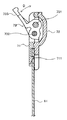
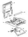
次に、図3〜図6を参照して、球戻り防止装置7の構造について説明する。なお、図3は、球戻り防止装置7を内レール61に取り付けた状態を上側から見た一例を示す図である。図4は、球戻り防止装置7を内レール61に取り付けた状態を下側から見た一例を示す図である。図5は、球戻り防止装置7を内レール61に取り付けた状態を側方から見た一例を示す、図3のC−C線断面図である。図6は、球戻り防止装置7の内部構造の一例を示す分解斜視図である。   Next, the structure of the ball return prevention device 7 will be described with reference to FIGS. FIG. 3 is a view showing an example in which the ball return preventing device 7 is attached to the inner rail 61 as viewed from above. FIG. 4 is a diagram illustrating an example of a state in which the ball return preventing device 7 is attached to the inner rail 61 as viewed from below. FIG. 5 is a cross-sectional view taken along the line CC of FIG. 3, showing an example of a state where the ball return prevention device 7 is attached to the inner rail 61 as viewed from the side. FIG. 6 is an exploded perspective view showing an example of the internal structure of the ball return prevention device 7.

図3〜図6において、球戻り防止装置7は、上側本体71、下側本体72、傾動部材73、支軸731、および錘732を備えている。例えば、上側本体71、下側本体72、および傾動部材73は、例えば合成樹脂により成形されて形成される。また、支軸731は、ステンレス等の金属の棒で構成され、傾動部材73に貫挿される。また、錘732は、金属製ビス等の所定重さの金属部材で構成され、傾動部材73の所定箇所に取り付けられる。そして、大略的には、傾動部材73に貫挿された支軸731の両端部を軸支して挟み込んだ状態で、上側本体71の下面と下側本体72の上面とが接合されて組み立てられる。   3 to 6, the ball return prevention device 7 includes an upper body 71, a lower body 72, a tilting member 73, a support shaft 731, and a weight 732. For example, the upper body 71, the lower body 72, and the tilting member 73 are formed by molding, for example, with a synthetic resin. The support shaft 731 is made of a metal rod such as stainless steel and is inserted into the tilting member 73. The weight 732 is formed of a metal member having a predetermined weight such as a metal screw, and is attached to a predetermined portion of the tilting member 73. In general, the lower surface of the upper main body 71 and the upper surface of the lower main body 72 are joined and assembled in a state where both ends of the support shaft 731 inserted through the tilting member 73 are pivotally supported and sandwiched. .

上側本体71は、その中央部に傾動部材73の一部が配置される開口部が形成された略方形枠状であり、該両側辺部の内面に支軸731の両端部を軸支するための一対の半円状の軸受溝を形成する。また、上側本体71の下辺部の中央から板バネ状の弾性片が延設されており、当該弾性片の下面(すなわち、下側本体72と接合される際の下側本体72側となる面)に円柱状の係合突起711が形成されている。なお、係合突起711は、上側本体71と下側本体72とが接合された際、外部に露出する位置に形成される。また、下側本体72と接合される上側本体71の下面には、下側本体72の上面と嵌合する凹凸部(例えば、凹部)が形成されている。   The upper main body 71 has a substantially rectangular frame shape in which an opening in which a part of the tilting member 73 is disposed is formed at the center, and both end portions of the support shaft 731 are pivotally supported on the inner surfaces of both side portions. A pair of semicircular bearing grooves is formed. A leaf spring-like elastic piece extends from the center of the lower side of the upper main body 71, and the lower surface of the elastic piece (that is, the surface on the lower main body 72 side when joined to the lower main body 72). ) Is formed with a cylindrical engagement protrusion 711. The engagement protrusion 711 is formed at a position exposed to the outside when the upper body 71 and the lower body 72 are joined. In addition, on the lower surface of the upper main body 71 joined to the lower main body 72, an uneven portion (for example, a concave portion) that fits with the upper surface of the lower main body 72 is formed.

下側本体72は、上側本体71の略方形枠内に係合されて接合可能な板状部材であり、上側本体71と接合される下側本体72の上面には、上側本体71の下面と嵌合する凹凸部(例えば、凸部)が形成されている。また、下側本体72は、上側本体71と接合された際に、上記軸受溝の直下位置に配置される一対の軸受突起が形成されている。   The lower main body 72 is a plate-like member that can be engaged and joined in a substantially rectangular frame of the upper main body 71, and the upper surface of the lower main body 72 joined to the upper main body 71 is connected to the lower surface of the upper main body 71. An uneven portion (for example, a convex portion) to be fitted is formed. Further, the lower main body 72 is formed with a pair of bearing protrusions that are disposed immediately below the bearing groove when joined to the upper main body 71.

傾動部材73は、支軸731を貫挿するための貫挿孔733が形成され、貫挿孔733の下部に錘732が取り付けられる取付孔734が形成されている。また、傾動部材73は、貫挿孔733を挟んで取付孔734と反対側となる、貫挿孔733の斜め上方に球止め片735が形成される。そして、球止め片735の最先端部が下方(すなわち、上側本体71側)へ湾曲して形成される。   The tilting member 73 is formed with an insertion hole 733 for inserting the support shaft 731, and an attachment hole 734 to which a weight 732 is attached is formed below the insertion hole 733. Further, the tilting member 73 has a ball stopper piece 735 formed obliquely above the through hole 733 on the opposite side of the mounting hole 734 across the through hole 733. Then, the most distal end portion of the ball stopper piece 735 is formed to curve downward (that is, on the upper body 71 side).

球戻り防止装置7を組み立てる際、錘732を取付孔734に取り付けた後、傾動部材73の下部(貫挿孔733および取付孔734が形成されている部位)を上側本体71の開口部にその上面側から入れて、上側本体71の下面側に当該下部を突出させた状態で貫挿孔733に支軸731を貫挿して、支軸731の両端部を上側本体71の軸受溝内に配置する。そして、接着や溶着等によって下側本体72を上側本体71に接合して固定する。これにより、支軸731の両端部が上側本体71の軸受溝と下側本体72の軸受突起との間でそれぞれ挟持される。また、図5に示したように上側本体71の下部と下側本体72の下部との間に、内レール61の上側端部に挿着されるスリット状の隙間が形成される。さらに、上側本体71の開口部および下側本体72の上面によって囲まれ、球戻り防止装置7が内レール61の上側端部に挿着された際に、発射球通路63に面する空間が形成される。   When assembling the ball return prevention device 7, after the weight 732 is attached to the attachment hole 734, the lower part of the tilting member 73 (the part where the through hole 733 and the attachment hole 734 are formed) is placed in the opening of the upper body 71. The support shaft 731 is inserted into the insertion hole 733 with the lower portion protruding from the upper surface side and the lower portion protruded from the upper body 71, and both ends of the support shaft 731 are disposed in the bearing grooves of the upper body 71. To do. Then, the lower main body 72 is joined and fixed to the upper main body 71 by adhesion or welding. As a result, both end portions of the support shaft 731 are sandwiched between the bearing groove of the upper body 71 and the bearing protrusion of the lower body 72. Further, as shown in FIG. 5, a slit-like gap is formed between the lower portion of the upper body 71 and the lower portion of the lower body 72 and is inserted into the upper end of the inner rail 61. Furthermore, a space that is surrounded by the opening of the upper body 71 and the upper surface of the lower body 72 and faces the launching ball passage 63 when the ball return prevention device 7 is inserted into the upper end of the inner rail 61 is formed. Is done.

一方、図3および図4に示すように、内レール61は、固定部材(例えば、釘)611によって、遊技盤2の前面に固設される。また、内レール61の上側端部には、当該端面から所定距離の位置となる位置に、係合突起711と係合可能な貫通孔が形成されている。そして、球戻り防止装置7は、上側本体71を上側(すなわち、外レール62側)にして上記スリット状の隙間を内レール61の上側端部に挿入すると、係合突起711と内レール61の貫通孔とが係合して内レール61の上側端部に固定される。   On the other hand, as shown in FIGS. 3 and 4, the inner rail 61 is fixed to the front surface of the game board 2 by a fixing member (for example, a nail) 611. In addition, a through hole that can be engaged with the engagement protrusion 711 is formed in the upper end portion of the inner rail 61 at a position at a predetermined distance from the end surface. Then, the ball return prevention device 7 inserts the slit-shaped gap into the upper end portion of the inner rail 61 with the upper body 71 on the upper side (that is, on the outer rail 62 side). The through hole engages and is fixed to the upper end of the inner rail 61.

内レール61の上側端部に取り付けられた球戻り防止装置7は、傾動部材73が支軸731を中心に傾動可能な状態で発射球通路63側に配置されるとともに、球止め片735の先端部が最上位置に配置される。これによって、球戻り防止装置7の球止め片735の先端部は、内レール61の上側端部を上方へ延長した最上位置に配置されることになるため、発射球通路63から遊技領域20への遊技球出口の最端に突出した状態で配置されることになる。   The ball return prevention device 7 attached to the upper end portion of the inner rail 61 is disposed on the launching ball passage 63 side in a state where the tilting member 73 can tilt around the support shaft 731, and the tip of the ball stopper piece 735. The part is arranged at the uppermost position. As a result, the tip of the ball stop piece 735 of the ball return prevention device 7 is disposed at the uppermost position extending upward from the upper end of the inner rail 61, so that the launch ball passage 63 moves to the game area 20. It will be arranged in a state of protruding to the extreme end of the game ball outlet.

図5に示すように、傾動部材73は、図示D方向へ傾動可能となっている。例えば、傾動部材73は、錘732が取り付けられる下部側と球止め片735が形成されている上部側との重量バランスによって、常態では球止め片735が発射球通路63側へ起立するように傾動し、錘732が取り付けられる部位が上記空間内に退避する。そして、発射球通路63へ遊技球が発射されて当該遊技球が球止め片735に当たると、傾動部材73が支軸731を支点として球止め片735が発射球通路63から下方へ退避し、錘732が取り付けられる部位が上記空間内から発射球通路63側へ移動するように傾動する。これによって、発射球通路63へ発射された遊技球は、球止め片735に妨げられることなく遊技領域20へ放出される。また、遊技球が発射球通路63から遊技領域20への遊技球出口を通過すると、上記重量バランスによって再び常態となって球止め片735が発射球通路63側へ起立するように傾動部材73が傾動する。この常態において、遊技領域20に一旦放出された遊技球が上記遊技球出口へ跳ね返って球止め片735に当たった場合、錘732が取り付けられる部位が下側本体72の上面等と当接することによって、球止め片735が形成されている上部側が発射球通路63側を遊技球発射方向の反対となる方向へさらに倒れるように傾動部材73が傾動することがない。したがって、遊技領域20に放出された遊技球が球止め片735に当たったとしても、当該遊技球が発射球通路63に戻ることはない。   As shown in FIG. 5, the tilting member 73 can tilt in the direction D shown in the figure. For example, the tilting member 73 tilts so that the ball stopper piece 735 stands up to the launching ball passage 63 side normally due to the weight balance between the lower side to which the weight 732 is attached and the upper side on which the ball stopper piece 735 is formed. And the site | part to which the weight 732 is attached retracts | saves in the said space. When the game ball is launched into the launch ball passage 63 and the game ball hits the ball stop piece 735, the tilting member 73 is retracted downward from the launch ball passage 63 with the pivot 731 as a fulcrum, and the weight The portion to which 732 is attached tilts so as to move from the space to the launching ball passage 63 side. Thereby, the game ball launched into the launch ball passage 63 is released to the game area 20 without being blocked by the ball stopper piece 735. In addition, when the game ball passes the game ball exit from the launch ball passage 63 to the game area 20, the tilting member 73 becomes normal so that the ball stopper piece 735 stands up toward the launch ball passage 63 again due to the weight balance. Tilt. In this normal state, when the game ball once released to the game area 20 bounces back to the game ball outlet and hits the ball stopper piece 735, the part to which the weight 732 is attached comes into contact with the upper surface of the lower main body 72 and the like. The tilting member 73 is not tilted so that the upper side where the ball stopper piece 735 is formed further falls in the direction opposite to the game ball launch direction on the launch ball passage 63 side. Therefore, even if the game ball released to the game area 20 hits the ball stop piece 735, the game ball does not return to the launch ball passage 63.

次に、球戻り防止装置7、および、発光素子90の位置関係について説明する。本実施形態において、発光素子90は、遊技盤2に埋設されている。その埋設位置としては、傾動部材73の後側であって、上記傾動部材73が常態のときは、発光素子90が遊技機1の正面側から視認され(図7参照)、傾動部材73が傾動したときは、発光素子90が傾動部材73の一部に隠されるような位置(図8参照)に埋設される。   Next, the positional relationship between the ball return prevention device 7 and the light emitting element 90 will be described. In the present embodiment, the light emitting element 90 is embedded in the game board 2. The embedded position is the rear side of the tilting member 73. When the tilting member 73 is in a normal state, the light emitting element 90 is visually recognized from the front side of the gaming machine 1 (see FIG. 7), and the tilting member 73 tilts. In this case, the light emitting element 90 is embedded in a position (see FIG. 8) where it is hidden by a part of the tilting member 73.

次に、図9および図10を参照して、細線を接着した遊技球を用いた不正が行われていることが球戻り防止装置7、および、発光素子90によって発見されるメカニズムの一例について説明する。なお、図9は、遊技球が発射された際の球戻り防止装置7の状態の一例を示す球戻り防止装置7の要部断面図である。図10は、細線を接着した遊技球を用いた不正が行われている状態の一例を示す球戻り防止装置7の要部断面図である。   Next, with reference to FIG. 9 and FIG. 10, an example of a mechanism that is detected by the ball return prevention device 7 and the light emitting element 90 that fraud using a game ball bonded with a thin line is performed will be described. To do. FIG. 9 is a cross-sectional view of the main part of the ball return prevention device 7 showing an example of the state of the ball return prevention device 7 when a game ball is launched. FIG. 10 is a cross-sectional view of a main part of the ball return prevention device 7 showing an example of a state in which fraud is performed using a game ball to which a thin line is bonded.

図9に示すように、傾動部材73は、常態では球止め片735が発射球通路63側へ起立するように傾動しているため、V字切欠形成部のV字切欠が発射球通路63側に向かって開口している姿勢となる。また、発光素子90は常時発光している状態であるため、この状態であれば、発光素子90からの光が視認可能である。そして、図示F方向に移動している遊技球のように、発射球通路63へ正規な遊技球や細線が接着された不正遊技球が発射されて当該遊技球が球止め片735に当たると、球止め片735が発射球通路63から下方へ退避するように傾動部材73が傾動する。その結果、上記図8で示したように、発光素子90が傾動部材73の一部によって一時的に隠された状態となる。その後、発射球通路63へ発射された遊技球は、球止め片735に妨げられることなく遊技領域20へ放出される。その結果、傾動部材73は元の姿勢に戻り、発光素子90は視認できる状態となる。   As shown in FIG. 9, since the tilting member 73 is tilted so that the ball stopper piece 735 stands up toward the firing ball passage 63 in the normal state, the V-shaped notch of the V-shaped notch forming portion is on the firing ball passage 63 side. The posture is open toward In addition, since the light emitting element 90 is in a state of always emitting light, in this state, light from the light emitting element 90 is visible. Then, like a game ball moving in the direction F in the figure, when a regular game ball or an illegal game ball to which a thin line is bonded is launched into the launch ball passage 63 and the game ball hits the ball stop piece 735, The tilting member 73 tilts so that the stop piece 735 is retracted downward from the firing ball passage 63. As a result, as shown in FIG. 8, the light emitting element 90 is temporarily hidden by a part of the tilting member 73. Thereafter, the game ball launched into the launch ball passage 63 is released to the game area 20 without being blocked by the ball stopper piece 735. As a result, the tilting member 73 returns to the original posture, and the light emitting element 90 becomes visible.

ここで、正規の遊技球が発射球通路63から遊技領域20への遊技球出口を通過すると、再び常態となって球止め片735が発射球通路63側へ起立するように傾動部材73が傾動する。これによって、遊技領域20に一旦放出された正規の遊技球が上記遊技球出口へ跳ね返ってきても、当該遊技球が球止め片735に当たって発射球通路63に戻ることはない。   Here, when the regular game ball passes the game ball exit from the launch ball passage 63 to the game area 20, the tilting member 73 tilts so that the ball stopper piece 735 stands up toward the launch ball passage 63 again. To do. As a result, even if a regular game ball once released to the game area 20 bounces back to the game ball outlet, the game ball does not hit the ball stop piece 735 and return to the launch ball passage 63.

また、正規の遊技球は、例えば0.6秒間隔で打ち出される。そのため、正規の遊技球が発射球通路63から遊技領域20への遊技球出口を通過することが繰り返されることで、傾動部材73の姿勢変化(上記図7および図8参照)が一定の周期(0.6秒毎)で繰り返されることになる。その結果、常時発光している発光素子90が点滅しているように見えることになる。これにより、例えばホール店員が遊技機1の正面側から当該発光素子90の位置を見たとき、発光素子90が点滅しているに見えれば、正規の遊技球を用いて遊技している状態であると考えられる。なお、遊技機1が遊技されていない状態であれば、発光素子90は発光(点灯)状態を維持しているように見えることになる。   In addition, regular game balls are launched at intervals of 0.6 seconds, for example. Therefore, when the regular game ball is repeatedly passed through the game ball exit from the launch ball passage 63 to the game area 20, the posture change of the tilting member 73 (see FIGS. 7 and 8 above) is constant (see FIG. 7). Will be repeated every 0.6 seconds). As a result, the light emitting element 90 that always emits light appears to blink. Thus, for example, when a hall clerk looks at the position of the light emitting element 90 from the front side of the gaming machine 1, if the light emitting element 90 appears to blink, it means that a game is being played using a regular game ball. It is believed that there is. If the gaming machine 1 is not being played, the light emitting element 90 will appear to maintain the light emitting (lighted) state.

一方、図10に示すように、細線が接着された不正遊技球が発射球通路63から遊技領域20への遊技球出口を通過すると、球止め片735に当該遊技球に接着されている細線が引っかかる状態となる。そして、不正遊技球に接着された上記細線の一方端が当該不正遊技球の自由落下によって遊技領域20内を下方へ移動するとともに、上記細線の他方端が不正な遊技者の手元側に維持されているため、不正遊技球に引っ張られた細線が傾動部材73を傾動させる。その結果、傾動部材73の姿勢としては、傾動したままの状態、すなわち、発光素子90を覆い隠す状態が維持され、発光素子90の光を視認することができない状態となる。つまり、遊技機1の正面側から当該発光素子90の位置を見たとき、発光素子90の光が視認できない状態(ホール店員からすると、消灯しているように見える)であれば、上記のような不正な遊技球が用いられている状態であると考えられる。そのため、当該発光素子90の発光態様を監視することで、細線を接着した遊技球を用いた不正が行われているか否かを容易に発見することが可能となる。   On the other hand, as shown in FIG. 10, when the illegal game ball to which the fine line is bonded passes through the game ball exit from the launch ball passage 63 to the game area 20, the fine line bonded to the game ball is attached to the ball stopper piece 735. It will be caught. Then, one end of the fine line bonded to the illegal game ball moves downward in the game area 20 by the free fall of the illegal game ball, and the other end of the fine line is maintained on the hand side of the unauthorized player. Therefore, the thin line pulled by the illegal game ball tilts the tilting member 73. As a result, as the posture of the tilting member 73, the tilted state, that is, the state of covering the light emitting element 90 is maintained, and the light of the light emitting element 90 cannot be visually recognized. In other words, when the light emitting device 90 is viewed from the front side of the gaming machine 1 and the light of the light emitting device 90 is not visible (when viewed from the hall clerk), it is as described above. This is considered to be a state where an illegal game ball is used. Therefore, by monitoring the light emission mode of the light emitting element 90, it is possible to easily find out whether fraud using a game ball to which a thin line is bonded is being performed.

このように、本発明の球戻り防止装置、および、その近傍に埋設された発光素子90によれば、細線を接着した遊技球を用いた不正が行われた場合、発光素子が(ホール店員から見て)視認できない状態となるため、発光素子90の発光態様が、消灯しているように見えるか否かを監視することで、細線を接着した遊技球を用いた不正を容易に発見することが可能となる。また、当該構成の実現についても、例えばLEDを1個追加して埋設し、これを常時発光状態に設定すればよいだけであるため、多大なコストをかけることなく、容易に実現することが可能である。また、発光素子90の発光制御についても、既存のランプ制御部をそのまま流用すればよく、当該発光素子90の制御のために別途の制御部等を設ける必要もない。   As described above, according to the ball return prevention device of the present invention and the light emitting element 90 embedded in the vicinity thereof, when a fraud using a game ball to which a thin wire is bonded is performed, the light emitting element is Since it becomes invisible, it is easy to detect fraud using a game ball to which a thin line is attached by monitoring whether or not the light emission mode of the light emitting element 90 seems to be turned off. Is possible. In addition, the configuration can be easily realized without adding much cost because, for example, it is only necessary to embed one LED and embed it and set it to a constant light emitting state. It is. For the light emission control of the light emitting element 90, the existing lamp control unit may be used as it is, and it is not necessary to provide a separate control unit for controlling the light emitting element 90.

なお、上述した説明では、発光素子90が常時発光している場合を例に挙げたが、この他、例えば、発光素子90を常時点滅させるように制御してもよい。この場合は、点滅する間隔を、遊技球が打ち出される間隔(例えば0.6秒)と異なる間隔とすればよい。このように構成した場合でも、発光態様が消灯状態であるか否かをホール店員が注目・監視することで、不正行為を容易に発見することはできる。   In the above description, the case where the light emitting element 90 always emits light has been described as an example. However, for example, the light emitting element 90 may be controlled to blink constantly. In this case, the blinking interval may be different from the interval at which the game ball is launched (for example, 0.6 seconds). Even in such a configuration, the hall clerk pays attention to and monitors whether or not the light emission mode is in the extinguished state, so that an illegal act can be easily found.

また、発光素子90の埋設位置についても、上記図xで示したような位置の他、例えば、図11および図12に示すような、球止め片735で隠されるような位置等でもよい。つまり、傾動部材73が常態のときには視認できるが、傾動したときは傾動部材73に隠されて視認できなくなるような位置であれば、どのような位置でも良い。ただ、発光素子90の大きさ(LEDの直径等)と傾動部材73の各部の厚みとの関係からすれば、錘732がある側の部分で隠されるような位置のほうが好ましい。例えば、球止め片735で隠されるような位置にした場合、球止め片735の厚みがLEDの直径より薄くなる場合も考えられ、球止め片735の厚みを増す等の加工作業が別途必要となる可能性があるためである。   Further, the buried position of the light emitting element 90 may be, for example, a position hidden by the ball stopper piece 735 as shown in FIGS. 11 and 12 in addition to the position shown in FIG. That is, any position is acceptable as long as the tilting member 73 is visible when the tilting member 73 is in a normal state but is hidden by the tilting member 73 and cannot be viewed when tilting. However, in view of the relationship between the size of the light emitting element 90 (LED diameter and the like) and the thickness of each part of the tilting member 73, the position where the weight 732 is hidden by the part on the side is more preferable. For example, when the position is hidden by the ball stopper piece 735, the thickness of the ball stopper piece 735 may be smaller than the diameter of the LED, and additional processing work such as increasing the thickness of the ball stopper piece 735 is required. This is because there is a possibility of becoming.

更には、上記実施形態では、傾動部材73が常態のときには視認でき、傾動したときは傾動部材73に隠されて視認できなくなる場合を例に挙げた。この他、図13および図14に示すように、傾動部材73が常態のときには傾動部材73に隠されて視認できず、傾動したときに視認できるような位置に発光素子90を埋設するようにしてもよい。この場合は、発光素子90が消灯、あるいは点滅しているときは不正な遊技球は用いられておらず、発光素子90が点灯状態を維持している場合は、不正な遊技球が用いられている状態であると判別でき、上記同様に、細線を接着した遊技球を用いた不正が行われているか否かを容易に発見することが可能となる。   Furthermore, in the above-described embodiment, the case where the tilting member 73 is visible when the tilting member 73 is in a normal state, and when the tilting member 73 is tilted, it is hidden by the tilting member 73 and cannot be viewed. In addition, as shown in FIG. 13 and FIG. 14, the light emitting element 90 is embedded at a position where the tilting member 73 is hidden by the tilting member 73 when the tilting member 73 is in a normal state and cannot be visually recognized. Also good. In this case, an illegal game ball is not used when the light emitting element 90 is turned off or blinking, and an illegal game ball is used when the light emitting element 90 is kept on. In the same manner as described above, it is possible to easily find out whether or not fraud using a game ball to which a thin line is bonded is being performed.

また、上記実施形態では、傾動部材73を有する球戻り防止装置7を用いた場合を例に挙げた。そして、当該球戻り防止装置7は、内レール61の上側端部に取り付けられていた。このような構成に限らず、上記傾動部材73のような動作をするような部材であれば、必ずしも球戻り防止装置7でなくてもよい。まだ、その取り付け位置も、内レール61の上側端部に限らず、その近傍位置に取り付けるようにしても良い。例えば、図15に示すように、傾動部材73のような動作をする部材を、一種の役物として、内レール61の上側端の近傍(内レール61のほぼ延長線上になるような位置)に取り付けてもよい。そして、当該役物の近傍に上記発光素子90を埋設すればよい。また、この場合、内レール61と当該役物との間隔としては、遊技球がその間を下方に向けて通過できないような間隔で配置すればよい。なお、図15では便宜上、役物の形状を傾動部材73と同様の形状で示しているが、この形状に限るものではないことは言うまでもない。遊技球が接触することで姿勢が一時的に変化するような形状であり、変化する前の姿勢と後の姿勢とで、いずれか一方の姿勢では発光素子90が視認でき、他方の姿勢のときは発光素子90を覆い隠すことで視認できなくなるような形状であれば、どのような形状でも良い。   Moreover, in the said embodiment, the case where the ball | bowl return prevention apparatus 7 which has the tilting member 73 was used was mentioned as an example. The ball return prevention device 7 is attached to the upper end of the inner rail 61. The configuration is not limited to such a configuration, and the ball return prevention device 7 is not necessarily required as long as the member operates like the tilting member 73. Still, the attachment position is not limited to the upper end portion of the inner rail 61, and may be attached to the vicinity thereof. For example, as shown in FIG. 15, a member that operates like a tilting member 73 is used as a kind of accessory in the vicinity of the upper end of the inner rail 61 (a position that is substantially on the extension line of the inner rail 61). It may be attached. And the said light emitting element 90 should just be embed | buried in the vicinity of the said accessory. Further, in this case, the interval between the inner rail 61 and the accessory may be arranged at an interval such that the game balls cannot pass downward therebetween. In FIG. 15, for convenience, the shape of the accessory is shown in the same shape as the tilting member 73, but it is needless to say that the shape is not limited to this shape. The shape is such that the posture changes temporarily when the game ball comes into contact, and the light emitting element 90 can be visually recognized in either posture before and after the change. Any shape may be used as long as the shape cannot be visually recognized by covering the light emitting element 90.

なお、上述した説明では、遊技者が行う不正行為の例として、細線を接着した不正遊技球を用いて、遊技機1に設けられた第1始動口25a等の始動口や普通入賞口29へ入賞するように当該不正遊技球を導いたり、当該入賞状態が連続して発生するように細線を出し入れして当該不正遊技球を往復移動させたりすることを挙げたが、他の不正行為の発見も容易になることは言うまでもない。例えば、上記不正遊技球を用いて、遊技機1に設けられた入賞や抽選に関する他の役物(例えば、ゲート27、第2始動口25b、大入賞口28)への不正な入賞や抽選を生じさせるような不正も防止することができる。また、細線に遊技球以外の物体を接着した道具を用いた不正であっても、球戻り防止装置を通過した場合に上記発光素子の発光態様が消灯した状態に見えるため、、当該不正を容易に発見することが可能となる。   In the above description, as an example of the cheating performed by the player, the cheating game ball to which the thin line is adhered is used as an example of the cheating action to the starting port such as the first starting port 25a provided in the gaming machine 1 or the normal winning port 29. Although it was mentioned that the illegal gaming ball was guided to win a prize, or that the illegal gaming ball was reciprocated by inserting / removing a thin line so that the winning state was continuously generated, but other illegal acts were discovered. Needless to say, it will be easier. For example, by using the above-mentioned illegal gaming balls, illegal winning or lottery to other items (for example, the gate 27, the second start opening 25b, the big winning opening 28) related to winning or lottery provided in the gaming machine 1 is performed. It is also possible to prevent fraud that may occur. In addition, even if it is fraudulent using a tool in which an object other than a game ball is bonded to a thin line, the light emission mode of the light emitting element appears to be extinguished when passing through the ball return prevention device. It will be possible to discover.

また、上述した遊技機1に設けられている各構成要素の形状、数、および設置位置等は、単なる一例に過ぎず他の形状、数、および設置位置であっても、本発明を実現できることは言うまでもない。   In addition, the shape, number, installation position, and the like of each component provided in the gaming machine 1 described above are merely examples, and the present invention can be realized even with other shapes, numbers, and installation positions. Needless to say.

以上、本発明を詳細に説明してきたが、前述の説明はあらゆる点において本発明の例示にすぎず、その範囲を限定しようとするものではない。本発明の範囲を逸脱することなく種々の改良や変形を行うことができることは言うまでもない。本発明は、特許請求の範囲によってのみその範囲が解釈されるべきであることが理解される。また、当業者は、本発明の具体的な実施形態の記載から、本発明の記載および技術常識に基づいて等価な範囲を実施することができることが理解される。また、本明細書において使用される用語は、特に言及しない限り、当該分野で通常用いられる意味で用いられることが理解されるべきである。したがって、他に定義されない限り、本明細書中で使用される全ての専門用語および技術用語は、本発明の属する分野の当業者によって一般的に理解されるのと同じ意味を有する。矛盾する場合、本明細書(定義を含めて)が優先する。   Although the present invention has been described in detail above, the above description is merely illustrative of the present invention in all respects and is not intended to limit the scope thereof. It goes without saying that various improvements and modifications can be made without departing from the scope of the present invention. It is understood that the scope of the present invention should be construed only by the claims. Moreover, it is understood that those skilled in the art can implement an equivalent range from the description of the specific embodiments of the present invention based on the description of the present invention and the common general technical knowledge. In addition, it is to be understood that the terms used in the present specification are used in the meaning normally used in the art unless otherwise specified. Thus, unless defined otherwise, all technical and technical terms used herein have the same meaning as commonly understood by one of ordinary skill in the art to which this invention belongs. In case of conflict, the present specification, including definitions, will control.

以下、上記実施形態における作用効果について説明する。なお、特許請求の範囲の記載を解釈する際に、特許請求の範囲の記載によってのみその範囲が解釈されるべきであることが理解され、特許請求の範囲の記載と本作用効果の記載とが矛盾する場合には、特許請求の範囲の記載が優先する。また、本作用効果における括弧内の記載は、本発明の理解を助けるために上記実施形態との対応関係を示したものであって、本発明の範囲を何ら限定するものではない。   Hereinafter, the function and effect of the embodiment will be described. In interpreting the description of the scope of claims, it is understood that the scope should be interpreted only by the description of the scope of claims. In case of conflict, the claims will prevail. In addition, the description in parentheses in this operational effect indicates a correspondence relationship with the above-described embodiment in order to help understanding of the present invention, and does not limit the scope of the present invention.

上記実施形態においては、発光部は回動部材の後方であって、回動部材が第1の姿勢および第2の姿勢のいずれか一方の姿勢のときにのみ遊技盤の正面から視認できるような位置に埋設される。   In the above embodiment, the light emitting unit is behind the rotating member, and is visible from the front of the game board only when the rotating member is in one of the first posture and the second posture. Buried in position.

上記によれば、細線を接着した遊技球を用いた不正が行われた場合と行われていない場合とで、発光部の発光態様が異なるため、当該不正を容易に発見することができる。また、既存の遊技機の構成に発光部を1つ加えるだけですむため、多大なコストを掛けずに、不正を容易に発見することが可能な遊技機を構成できる。   According to the above, since the light emission mode of the light emitting unit is different depending on whether or not fraud is performed using a game ball to which a thin line is bonded, the fraud can be easily detected. In addition, since it is only necessary to add one light emitting unit to the configuration of the existing gaming machine, it is possible to configure a gaming machine that can easily detect fraud without enormous cost.

上記発光部は、遊技機が動作している間は常時発光状態であってもよい。   The light emitting unit may always be in a light emitting state while the gaming machine is operating.

上記によれば、細線を接着した遊技球を用いた不正が行われた場合、発光部からの光が視認できない状態となるため、不正を容易に発見することができる。また、発光部の発光制御についても、例えば点滅させるような制御を行う場合に比べて簡易な制御で済む。   According to the above, when a fraud using a game ball to which a thin line is bonded is performed, the light from the light emitting unit cannot be visually recognized, so that the fraud can be easily detected. Further, the light emission control of the light emitting unit may be simpler than that in the case of performing control such as blinking.

上記発光部は、回動部材の姿勢が当該発光部を視認できない姿勢のとき、当該回動部材の一部に隠されて視認できないような位置に埋設されてもよい。   The light emitting unit may be embedded at a position such that the light emitting unit is hidden by a part of the rotating member and cannot be visually recognized when the rotating member is in a position where the light emitting unit cannot be viewed.

上記によれば、細線を接着した遊技球を用いた不正が行われた場合、回動部材に隠されることで発光部からの光が視認できない状態となるため、発光部の発光態様に着目することで不正を容易に発見することができる。   According to the above, when a fraud using a game ball to which a thin wire is bonded is performed, the light from the light emitting unit cannot be visually recognized by being hidden by the rotating member, so pay attention to the light emission mode of the light emitting unit. By doing so, fraud can be easily detected.

上記回動部材は、前記第1の姿勢においては前記発射球通路側へ起立した姿勢となるとともに、前記第2の姿勢においては発射球通路から退避する方向へ傾倒する球止め片を有する球戻り防止部材であってもよい。   In the first posture, the rotating member is in a posture of standing on the side of the launching ball passage, and in the second posture, the turning member has a ball stop piece that tilts in a direction to retract from the launching ball passage. It may be a prevention member.

上記によれば、既存の球戻り防止部材を流用することができるため、既存の遊技機の構成に、例えばLEDを1つ加えるという構成の変更で済むため、不正を容易に発見することができる遊技機を低コストで構成することができる。   According to the above, since the existing ball return prevention member can be diverted, it is only necessary to change the configuration of adding one LED to the configuration of the existing gaming machine, so that fraud can be easily detected. A gaming machine can be configured at low cost.

1…遊技機
2…遊技盤
20…遊技領域
21…画像表示部
22…可動役物
23…盤ランプ
24…排出口
25a…第1始動口
25b…第2始動口
26…電動チューリップ
27…ゲート
28…大入賞口
29…普通入賞口
3…表示器
43…錠部
5…枠部材
51…ハンドル
52…レバー
53…停止ボタン

54…取り出しボタン
55…スピーカ
56…枠ランプ
57…演出ボタン
58…演出キー
59…皿
61…内レール
611…固定部材
62…外レール
63…発射球通路
7…球戻り防止装置
71…上側本体
711…係合突起
72…下側本体
73…傾動部材
731…支軸
732…錘
733…貫挿孔
734…取付孔
735…球止め片
DESCRIPTION OF SYMBOLS 1 ... Game machine 2 ... Game board 20 ... Game area 21 ... Image display part 22 ... Movable accessory 23 ... Board lamp 24 ... Discharge port 25a ... 1st start port 25b ... 2nd start port 26 ... Electric tulip 27 ... Gate 28 ... Big winning opening 29 ... Normal winning opening 3 ... Display 43 ... Lock part 5 ... Frame member 51 ... Handle 52 ... Lever 53 ... Stop button

54 ... Eject button 55 ... Speaker 56 ... Frame lamp 57 ... Production button 58 ... Production key 59 ... Dish 61 ... Inner rail 611 ... Fixing member 62 ... Outer rail 63 ... Launch ball passage 7 ... Ball return prevention device 71 ... Upper body 711 ... engaging protrusion 72 ... lower body 73 ... tilting member 731 ... support shaft 732 ... weight 733 ... penetration hole 734 ... mounting hole 735 ... ball stop piece

Claims (4)

遊技盤の前面に設けられた発射球通路の内側に固設される内レールの上側端部または当該上側端部の近傍に設けられ、発射球通路から進入した遊技球と接触可能な第1の姿勢と、遊技球の接触により一時的に変化する姿勢であって当該第1の姿勢とは異なる姿勢である第2の姿勢とに姿勢変化可能な回動部材と、
前記回動部材の後方に埋設される発光部とを備え、
前記発光部は、前記回動部材が前記第1の姿勢および第2の姿勢のいずれか一方の姿勢のときにのみ前記遊技盤の正面から視認できるような位置に埋設される、遊技機。
A first ball that is provided at or near the upper end of the inner rail that is fixed inside the firing ball passage provided on the front surface of the game board and that can contact the game ball that has entered from the launch ball passage. A rotating member capable of changing its posture between a posture and a second posture which is a posture which is temporarily changed by contact with a game ball and which is different from the first posture;
A light emitting portion embedded behind the rotating member,
The light emitting unit is a gaming machine that is embedded in a position that can be viewed from the front of the game board only when the rotating member is in one of the first posture and the second posture.
前記発光部は、前記遊技機が動作している間は常時発光状態である、請求項1に記載の遊技機。   The gaming machine according to claim 1, wherein the light emitting unit is always in a light emitting state while the gaming machine is operating. 前記発光部は、前記回動部材の姿勢が当該発光部を視認できない姿勢のとき、当該回動部材の一部に隠されて視認できないような位置に埋設される、請求項1に記載の遊技機。   2. The game according to claim 1, wherein the light emitting unit is embedded in a position such that the light emitting unit is hidden by a part of the rotating member and cannot be visually recognized when the rotating member is in a position where the light emitting unit cannot be visually recognized. Machine. 前記回動部材は、前記第1の姿勢においては前記発射球通路側へ起立した姿勢となるとともに、前記第2の姿勢においては発射球通路から退避する方向へ傾倒する球止め片を有する球戻り防止部材である、請求項1ないし3に記載の遊技機。   In the first posture, the rotating member is in a posture of standing on the side of the launching ball passage, and in the second posture, the turning member has a ball stop piece that tilts in a direction to retract from the launching ball passage. The gaming machine according to claim 1, which is a prevention member.
JP2011097530A 2011-04-25 2011-04-25 Game machine Active JP5111641B2 (en)

Priority Applications (1)

Application Number Priority Date Filing Date Title
JP2011097530A JP5111641B2 (en) 2011-04-25 2011-04-25 Game machine

Applications Claiming Priority (1)

Application Number Priority Date Filing Date Title
JP2011097530A JP5111641B2 (en) 2011-04-25 2011-04-25 Game machine

Publications (2)

Publication Number Publication Date
JP2012228322A JP2012228322A (en) 2012-11-22
JP5111641B2 true JP5111641B2 (en) 2013-01-09

Family

ID=47430424

Family Applications (1)

Application Number Title Priority Date Filing Date
JP2011097530A Active JP5111641B2 (en) 2011-04-25 2011-04-25 Game machine

Country Status (1)

Country Link
JP (1) JP5111641B2 (en)

Family Cites Families (4)

* Cited by examiner, † Cited by third party
Publication number Priority date Publication date Assignee Title
JPH0748294Y2 (en) * 1991-03-18 1995-11-08 株式会社共栄商会 Windmill for pachinko machine
JP4269085B2 (en) * 1998-05-19 2009-05-27 奥村遊機株式會社 Launching ball detector for pachinko machine
JP2005198718A (en) * 2004-01-13 2005-07-28 Aruze Corp Pinball game machine
JP5335548B2 (en) * 2009-05-13 2013-11-06 京楽産業.株式会社 Pachinko machine

Also Published As

Publication number Publication date
JP2012228322A (en) 2012-11-22

Similar Documents

Publication Publication Date Title
JP5702620B2 (en) Ball return prevention device
JP2009160028A (en) Winning hole unit and game machine
JP5111641B2 (en) Game machine
JP5240580B2 (en) Pachinko machine
JP5953010B2 (en) Pachinko machine
JP5126468B2 (en) Game machine
JP5392513B2 (en) Game machine
JP4916865B2 (en) Game machine
JP5346995B2 (en) Game machine
JP5099313B2 (en) Game machine
JP5877667B2 (en) Game machine
JP5099673B2 (en) Game machine
JP2015097963A (en) Game machine
JP2014140730A (en) Game machine
JP5804287B2 (en) Game machine
JP5392514B2 (en) Game machine
JP2019171211A5 (en)
JP5548911B2 (en) Game machine
JP2019171211A (en) Game machine
JP5099670B2 (en) Game machine
JP4895773B2 (en) Game machine
JP2008194299A5 (en)
JP2012091043A (en) Game machine
JP2018108522A (en) Game machine
JP2008125681A (en) Game machine

Legal Events

Date Code Title Description
TRDD Decision of grant or rejection written
A01 Written decision to grant a patent or to grant a registration (utility model)

Free format text: JAPANESE INTERMEDIATE CODE: A01

Effective date: 20120928

A01 Written decision to grant a patent or to grant a registration (utility model)

Free format text: JAPANESE INTERMEDIATE CODE: A01

A61 First payment of annual fees (during grant procedure)

Free format text: JAPANESE INTERMEDIATE CODE: A61

Effective date: 20121009

FPAY Renewal fee payment (event date is renewal date of database)

Free format text: PAYMENT UNTIL: 20151019

Year of fee payment: 3

R150 Certificate of patent or registration of utility model

Ref document number: 5111641

Country of ref document: JP

Free format text: JAPANESE INTERMEDIATE CODE: R150

Free format text: JAPANESE INTERMEDIATE CODE: R150

R250 Receipt of annual fees

Free format text: JAPANESE INTERMEDIATE CODE: R250

R250 Receipt of annual fees

Free format text: JAPANESE INTERMEDIATE CODE: R250

R250 Receipt of annual fees

Free format text: JAPANESE INTERMEDIATE CODE: R250