JP5111604B2 - Gas turbine apparatus and control method thereof - Google Patents
Gas turbine apparatus and control method thereof Download PDFInfo
- Publication number
- JP5111604B2 JP5111604B2 JP2010508808A JP2010508808A JP5111604B2 JP 5111604 B2 JP5111604 B2 JP 5111604B2 JP 2010508808 A JP2010508808 A JP 2010508808A JP 2010508808 A JP2010508808 A JP 2010508808A JP 5111604 B2 JP5111604 B2 JP 5111604B2
- Authority
- JP
- Japan
- Prior art keywords
- turbine
- axis
- wall
- combustor
- region
- Prior art date
- Legal status (The legal status is an assumption and is not a legal conclusion. Google has not performed a legal analysis and makes no representation as to the accuracy of the status listed.)
- Expired - Fee Related
Links
Images
Classifications
-
- F—MECHANICAL ENGINEERING; LIGHTING; HEATING; WEAPONS; BLASTING
- F02—COMBUSTION ENGINES; HOT-GAS OR COMBUSTION-PRODUCT ENGINE PLANTS
- F02C—GAS-TURBINE PLANTS; AIR INTAKES FOR JET-PROPULSION PLANTS; CONTROLLING FUEL SUPPLY IN AIR-BREATHING JET-PROPULSION PLANTS
- F02C6/00—Plural gas-turbine plants; Combinations of gas-turbine plants with other apparatus; Adaptations of gas- turbine plants for special use
- F02C6/003—Gas-turbine plants with heaters between turbine stages
Abstract
Description
本発明は、軸線を中心として回転可能なロータ軸に沿ってそれぞれ配置された第1タービンと第2タービンとその両タービン間に配置された自己点火式燃焼器とを有するガスタービン装置に関する。また本発明はそのタービン装置の制御方法に関する。 The present invention relates to a gas turbine device having a first turbine, a second turbine, and a self-ignition combustor disposed between the two turbines, which are respectively disposed along a rotor shaft that is rotatable about an axis. The present invention also relates to a method for controlling the turbine device.
2つのガスタービンを有するガスタービン装置の場合、順次的な燃焼が行われ、その燃焼のために、2つの例えば環状燃焼器および/又は環状缶形燃焼器が利用され、その一方の(第1)燃焼器は高圧側に配置され、他方の(第2)燃焼器は低圧側に配置されている。高圧燃焼器に圧縮空気が供給され、この圧縮空気は燃料と混合され、その混合気が点火される。高圧燃焼器の下流に第1ガスタービン、即ち、高圧タービンが配置され、この高圧タービンは高圧燃焼器で発生された燃焼ガスにより駆動される。その燃焼ガスはそこで部分膨張するが、高圧タービンから出る際に例えば900℃〜1400℃の比較的高い温度を有する。高圧タービンの下流に低圧燃焼器が配置され、この第2燃焼器は自己点火式に運転され、この第2燃焼器において特に第1燃焼器における燃焼時に未消費の残存空気が第2燃焼に関与される。この低圧燃焼器は本質的に環状貫流路の形状を有し、この環状貫流路に燃料が噴射注入される。高圧タービンからの燃焼ガスが850℃以上の温度を有する場合、噴射注入された燃料の自己点火が生ずる。低圧燃焼器は一般に2つの領域に分けられ、即ち、入口領域と燃焼領域に分けられ、その入口領域において高圧タービンからの燃焼ガスが燃料と混合され、燃焼領域においてガスタービン装置の第2燃焼過程が生ずる。低圧燃焼器に第2ガスタービン、特に低圧タービンが後置接続されている。低圧燃焼器の形成にとって、燃焼ガスと燃料が良好に混合するようにするために十分な長さを有することおよび完全燃焼のために燃焼器に十分長く滞留させることが重要である。 In the case of a gas turbine device having two gas turbines, sequential combustion is performed, and two, for example, an annular combustor and / or an annular can combustor are used for the combustion, ) The combustor is disposed on the high pressure side, and the other (second) combustor is disposed on the low pressure side. Compressed air is supplied to the high-pressure combustor, the compressed air is mixed with fuel, and the mixture is ignited. A first gas turbine, that is, a high-pressure turbine is disposed downstream of the high-pressure combustor, and the high-pressure turbine is driven by combustion gas generated in the high-pressure combustor. The combustion gas then partially expands but has a relatively high temperature, e.g. A low-pressure combustor is disposed downstream of the high-pressure turbine, and the second combustor is operated in a self-igniting manner. In this second combustor, particularly, remaining air that is not consumed during combustion in the first combustor is involved in the second combustion Is done. This low-pressure combustor essentially has the shape of an annular through passage, and fuel is injected into the annular through passage. When the combustion gas from the high pressure turbine has a temperature of 850 ° C. or higher, self-ignition of the injected fuel occurs. The low pressure combustor is generally divided into two regions: an inlet region and a combustion region, in which the combustion gas from the high pressure turbine is mixed with fuel, and in the combustion region the second combustion process of the gas turbine apparatus. Will occur. A second gas turbine, in particular a low pressure turbine, is connected downstream from the low pressure combustor. For the formation of a low-pressure combustor, it is important to have a sufficient length to ensure good mixing of the combustion gas and fuel and to stay long enough in the combustor for complete combustion.
冒頭に述べた形式のガスタービン装置は例えば特許文献1で知られている。この特許文献1には、第1タービンからの燃焼ガスの温度が第2燃焼器における自己点火場所の直前で測定され、その測定温度によって複数の燃焼器に対する燃料供給量が調整されるガスタービン装置の制御方法が記載されている。 A gas turbine apparatus of the type described at the beginning is known, for example, from US Pat. This Patent Document 1 discloses a gas turbine device in which the temperature of combustion gas from a first turbine is measured immediately before a self-ignition location in a second combustor, and the fuel supply amount to a plurality of combustors is adjusted by the measured temperature. The control method is described.
2つのタービン間に位置する環状燃焼器における長い通過時間ないし滞留時間を得るために、燃焼ガスにらせん状旋回運動が強制発生されるガスタービン装置が、特許文献2で知られている。そこでは燃焼器の下流に設置されたタービンに第1静翼列は存在せず、これによって、そのタービンの第1動翼列が上流に設置されたタービンからの旋回流で付勢される。
特許文献3に、共通ロータ軸上に配置された少なくとも2つのタービンを有するガスタービン装置が示されている。その後置された第2タービンは第1タービンより体積的に大きくされている。
A gas turbine device in which a helical swirling motion is forcibly generated in a combustion gas in order to obtain a long passage time or residence time in an annular combustor located between two turbines is known from US Pat. There, the first stationary blade row does not exist in the turbine installed downstream of the combustor, whereby the first moving blade row of the turbine is energized by the swirling flow from the turbine installed upstream.
Patent Document 3 discloses a gas turbine device having at least two turbines arranged on a common rotor shaft. The second turbine placed thereafter is larger in volume than the first turbine.
本発明の課題は、窒素酸化物の発生が低減され効率が向上されたガスタービン装置を提供することにある。また本発明の課題は、かかるガスタービン装置の制御方法を提供することにある。 An object of the present invention is to provide a gas turbine apparatus in which generation of nitrogen oxides is reduced and efficiency is improved. Moreover, the subject of this invention is providing the control method of this gas turbine apparatus.
第1の課題は本発明に基づいて、軸線を中心として回転可能なロータ軸に沿ってそれぞれ配置された第1タービンと第2タービンとその両タービン間に配置された自己点火式燃焼器とを有するガスタービン装置であって、第2タービンが軸線に関して第1タービンより大きな周径を有し、第2タービンが軸線に関して第1タービンより半径方向外側に配置されていることを特徴とするガスタービン装置によって解決される。 A first problem is based on the present invention, and includes a first turbine, a second turbine, and a self-ignition combustor disposed between the two turbines, which are respectively disposed along a rotor shaft that is rotatable about an axis. A gas turbine apparatus comprising: a gas turbine comprising: a second turbine having a larger diameter than the first turbine with respect to an axis ; and the second turbine disposed radially outward with respect to the axis. Solved by the device.
本発明は、第2タービンが第1タービンより大きな周径を有し、ないしは軸線に関して半径方向外側に配置されている場合、運転中において下流に配置されたタービンにガスタービン装置の効率を向上する特に良好な流れ状態が生ずるという考えを基礎としている。それにもかかわらずタービンの作動体積を維持するために、その高さは従来における低圧タービンの高さより小さくされている。ここでタービンの高さとは、タービンの半径方向内側壁と外側壁との距離を意味し、作動体積とはタービンの中空環状内部空間の体積を意味する。小さく選定された高さのために、第2タービンの静翼と動翼は比較的小形に形成される。その場合、回転軸線に対する翼の半径方向距離の増大につれて、タービンを回転運動させるために必要な力が小さくなるという有利な関係が存分に利用される。また、第2タービンを駆動するための改善された周辺条件が、製造に手間と経費がかかる翼の数を減少するために有利に利用される。さらに、翼の小形化および/又は数の減少は、冷却すべき翼面が公知の低圧タービンの場合より小さくなるので、冷却要求に有利に作用する。タービンが燃焼器からの燃焼ガスで駆動されるタービンであるので、これらのタービンはガスタービンと呼ばれる。このガスタービン装置の構成要素は共通ロータ軸に沿って配置される。あるいはまた、ガスタービン装置の高圧部および低圧部は異なった回転速度で回転する別個の軸に配置できる。 The present invention improves the efficiency of a gas turbine device in a turbine disposed downstream during operation when the second turbine has a larger peripheral diameter than the first turbine or is disposed radially outward with respect to the axis. It is based on the idea that a particularly good flow condition occurs. Nevertheless, in order to maintain the working volume of the turbine, its height is made smaller than that of conventional low pressure turbines. Here, the height of the turbine means the distance between the radially inner side wall and the outer side wall of the turbine, and the working volume means the volume of the hollow annular inner space of the turbine. Due to the small selected height, the stationary and moving blades of the second turbine are formed relatively small. In that case, the advantageous relationship that as the radial distance of the blades relative to the axis of rotation increases, the force required to rotate the turbine is reduced. Also, improved ambient conditions for driving the second turbine are advantageously utilized to reduce the number of blades that are laborious and expensive to manufacture. Furthermore, the downsizing and / or reduction in the number of blades favors the cooling requirements because the blade surface to be cooled is smaller than in known low-pressure turbines. These turbines are called gas turbines because the turbines are turbines that are driven by combustion gas from a combustor. The components of this gas turbine apparatus are arranged along a common rotor axis. Alternatively, the high and low pressure portions of the gas turbine apparatus can be located on separate shafts that rotate at different rotational speeds.
有利な実施態様において、第1タービンに隣接する燃焼器の入口領域はディフューザの形態に形成されている。ディフューザは横断面積が下流に向かって連続して特に定常的に拡大していることで特徴づけられる。燃焼ガス流は入口領域における徐々に増大する体積のために流れ方向において減速し、これによって、その滞留時間が増大する。これは第1タービンからの残存空気と噴射注入された燃料との特に良好な混合に対する最良条件となる。従って、入口領域をディフューザの形態に形成することによって、燃焼器は横断面積が一定している燃焼器より短くすることができる。 In an advantageous embodiment, the inlet region of the combustor adjacent to the first turbine is formed in the form of a diffuser. The diffuser is characterized by a particularly constant steady expansion of the cross-sectional area towards the downstream. The combustion gas flow is decelerated in the flow direction due to the gradually increasing volume in the inlet region, thereby increasing its residence time. This is the best condition for a particularly good mixing of the residual air from the first turbine and the injected fuel. Thus, by forming the inlet region in the form of a diffuser, the combustor can be made shorter than a combustor having a constant cross-sectional area.
ディフューザは、好適には、軸線に関して入口領域の半径方向外側壁の半径方向距離だけが増大していることによって形成されている。これは、いわば入口領域の外側形状だけしか変更されていないので、ディフューザを簡単な構造で実現できる。燃焼器の半径方向内側壁は変更されないままである。この場合、半径方向外側壁をロータ軸に対して適当に傾斜して形成すべき、半径方向外側にできた空間が利用され、これによって、入口領域において所望の流れパラメータの流れ状態が生ずる。 The diffuser is preferably formed by increasing only the radial distance of the radially outer wall of the inlet region with respect to the axis. In other words, only the outer shape of the entrance region is changed, so that the diffuser can be realized with a simple structure. The radially inner wall of the combustor remains unchanged. In this case, a radially outer space in which the radially outer wall is to be formed with a suitable inclination with respect to the rotor axis is used, which results in a flow condition of the desired flow parameter in the inlet region.
ディフューザに開口する燃料供給管が設けられている。この燃料供給管は、好適には、ディフューザの軸方向長さの約1/2、特に約1/3に相当するディフューザの前方域に開口している。ディフューザの始端における依然として大きな燃焼ガス流の速度により、この領域における平衡温度 は比較的低い。これは入口領域における燃料・残存空気混合気の自己点火を遅らせ、これによって、燃料が第1ガスタービンからの残存空気と特に良好に混合する。これはまた、燃焼過程中における窒素酸化物の発生を減少する。この燃料供給管の配置位置によって、ディフューザの大部分が燃料と残存空気とを混合するために利用され、その場合、燃料・残存空気混合気がディフューザ内に十分長く留まり、これにより、高い混合率が得られ、従って、燃焼器の全長は比較的短くできる。 A fuel supply pipe that opens to the diffuser is provided. The fuel supply pipe is preferably open in the front region of the diffuser corresponding to about 1/2, in particular about 1/3 of the axial length of the diffuser. Due to the still large combustion gas flow rate at the beginning of the diffuser, the equilibrium temperature in this region is relatively low. This delays the self-ignition of the fuel / residual air mixture in the inlet region, so that the fuel mixes particularly well with the residual air from the first gas turbine. This also reduces the generation of nitrogen oxides during the combustion process. Depending on the position of the fuel supply pipe, the majority of the diffuser is used to mix the fuel and the remaining air, in which case the fuel / residual air mixture stays in the diffuser long enough, resulting in a high mixing rate. Thus, the overall length of the combustor can be made relatively short.
有利な実施態様において、第2タービンに隣接する燃焼器の燃焼領域はノズルの形態に形成されている。その燃焼領域は入口領域と異なって横断面積が流れ方向に連続して特に定常的に狭まっている。燃料・残存空気混合気の燃焼後の燃焼ガスはノズルにおいて再び加速され、これによって、動圧が上昇し、従って、低圧タービンは加速された燃焼ガス流で駆動される。この構造は低圧タービンを駆動するために必要な圧力を得るために特に適している。 In an advantageous embodiment, the combustion region of the combustor adjacent to the second turbine is formed in the form of a nozzle. Unlike the inlet region, the combustion region has a cross-sectional area continuously narrowing continuously in the flow direction. The combustion gas after combustion of the fuel / residual air mixture is accelerated again at the nozzle, thereby increasing the dynamic pressure, and thus the low pressure turbine is driven by the accelerated combustion gas flow. This structure is particularly suitable for obtaining the pressure required to drive a low pressure turbine.
このノズルは、好適には、軸線に関して燃焼領域の半径方向内側壁の半径方向距離だけが増大するように形成されている。ディフューザの範囲で得られている半径方向外側壁の最大半径方向距離は燃焼領域と同じである。ノズルを形成するために、燃焼領域の半径方向内側壁だけが軸線に対して傾斜して形成され、これによって、その半径方向内側壁は流れ方向において軸線から半径方向に徐々に離れて延びている。 This nozzle is preferably configured such that only the radial distance of the radially inner wall of the combustion zone increases with respect to the axis. The maximum radial distance of the radially outer wall obtained in the area of the diffuser is the same as the combustion zone. In order to form the nozzle, only the radially inner wall of the combustion zone is formed inclined with respect to the axis, whereby the radially inner wall extends gradually away from the axis in the flow direction in the radial direction. .
目的に適って、入口領域と燃焼領域との間に混合領域が設けられ、この混合領域の半径方向内側壁および半径方向外側壁がそれぞれ軸線に対して入口領域の半径方向内側壁と同じ半径方向距離および燃焼領域の半径方向外側壁と同じ半径方向距離を有している。これによって、混合領域は燃焼器の最大横断面積の部分を形成している。その場合、燃焼ガス流は混合領域において減速され、ないしは極めて長い滞留時間を有し、これによって、燃料と第1タービンからの残存空気との最良混合が行われる。混合領域の適切に選定された長さによって、燃焼器における燃焼ガス流の所望の滞留時間が特に簡単に設定できる。また、その壁輪郭の選定された形状によって、燃焼ガスの逆流が防止される。さらに燃焼器のこのような設計によって、デッドスペースの形成が抑制される。
Suitably, a mixing region is provided between the inlet region and the combustion region, the radially inner wall and the radially outer wall of the mixing region being in the same radial direction as the radially inner wall of the inlet region with respect to the axis, respectively. It has the same radial distance as the distance and the radially outer wall of the combustion zone. Thereby, the mixing zone forms part of the maximum cross-sectional area of the combustor. In that case, the combustion gas stream is decelerated in the mixing zone or has a very long residence time, whereby the best mixing of the fuel with the remaining air from the first turbine takes place. With a suitably chosen length of the mixing zone, the desired residence time of the combustion gas stream in the combustor can be set particularly simply. Further, the backflow of the combustion gas is prevented by the selected shape of the wall contour. Further, such a design of the combustor suppresses the formation of dead space.
本発明の第2の課題は、軸線を中心として回転可能な共通ロータ軸に沿ってそれぞれ配置された第1タービンと第2タービンとその両タービン間に配置された自己点火式燃焼器とを有するガスタービン装置の制御方法であって、燃焼ガス流が第1タービンに続いて燃焼器を通して、軸線に関して第1タービンより半径方向外側に位置する第2タービンに導かれることを特徴とするガスタービン装置の制御方法によって解決される。 A second object of the present invention is to have a first turbine, a second turbine, and a self-ignition combustor disposed between the two turbines, which are respectively disposed along a common rotor shaft that is rotatable about an axis. A method for controlling a gas turbine device, wherein a flow of combustion gas is guided to a second turbine located radially outside the first turbine with respect to an axis through a combustor following the first turbine. It is solved by the control method.
ガスタービン装置について述べた利点および実施態様は本発明に基づく方法にも転用できる。 The advantages and embodiments described for the gas turbine device can also be transferred to the method according to the invention.
以下図を参照して本発明の実施例を詳細に説明する。 Hereinafter, embodiments of the present invention will be described in detail with reference to the drawings.
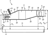
図におけるタービン装置2は主に、第1タービン4と第2タービン6とその両タービン4、6間に配置された環状燃焼器8とを有している。その両タービン4、6および燃焼器8は軸線12を中心として回転可能に配置された共通ロータ軸10上に位置している。この実施例において第1タービン4は発電所の高圧ガスタービン、第2タービン6は低圧ガスタービンである。
The
高圧タービン4に図示されていない前方燃焼器が前置されている。この前方燃焼器において燃料・空気混合気が燃焼され、その燃焼ガスにより高圧ガスタービン4の翼が付勢される。図において高圧タービン4の最終静翼列が静翼14で示され、最終動翼列が動翼16で示されている。
A high-pressure turbine 4 is provided with a front combustor (not shown). In this forward combustor, the fuel / air mixture is combusted, and the blades of the high-pressure gas turbine 4 are energized by the combustion gas. In the figure, the final stationary blade row of the high-pressure turbine 4 is indicated by a
高圧タービン4を貫流する燃焼ガスは燃焼過程に関与しなかった空気をなお含んでいる。その残存空気は矢印Lで示されている。残存空気Lは高圧タービン4の通過後に燃焼器8に導かれる。この実施例においてその燃焼器8は3つの領域、即ち、入口領域18と混合領域20と燃焼領域22とから成っている。入口領域18の開始点に燃料供給管24が開口し、この燃料供給管24を介して特に気体状の燃料Bが燃焼器18に供給される。入口領域18並びにその次の混合領域20において残存空気Lと燃料Bとの混合が行われ、その混合気は次に燃焼領域22において850℃より高い温度に達して点火する。
The combustion gas flowing through the high pressure turbine 4 still contains air that was not involved in the combustion process. The remaining air is indicated by an arrow L. The remaining air L is guided to the combustor 8 after passing through the high-pressure turbine 4. In this embodiment, the combustor 8 comprises three regions: an
燃焼器8からの燃焼ガス流は最終的に低圧燃焼器6に導かれる。この低圧燃焼器6において第1静翼列が静翼26で示され、第1動翼列が動翼28で示されている。
The combustion gas stream from the combustor 8 is finally led to the low pressure combustor 6. In the low-pressure combustor 6, the first stationary blade row is indicated by a
横断面で見て第1、第2タービン4、6および燃焼器8はそれぞれ内壁とも呼ばれる円筒状の半径方向内側壁30、30′、30″を有し、これらの内側壁は特に同心的に配置された外壁とも呼ばれる半径方向外側壁32、32′、32″で包囲されている。その内側壁30、30′、30″はロータ軸10に隣接しているか、ロータ軸10自体で形成されている。従って、それらの内側壁と外側壁との間にそれぞれ環状空間が形成されている。外側壁32、32′、32″はガスタービン装置のそれぞれの構成要素4、6、8の覆いとなっており、特に単一の車室の形態に結合される。
Viewed in cross-section, the first and second turbines 4, 6 and the combustor 8 each have a cylindrical radial
第1タービン4の内側壁30は軸線12に対して半径方向距離Ri1を有し、外側壁32は半径方向距離Ra1を有している。図示されたタービン装置2において、第2タービン6は軸線12に関して第1タービン4より半径方向外側に配置されている。即ち、第2タービン6の内側壁30″は軸線12に対して半径方向距離Ri1より大きな半径方向距離Ri2を有している。同時に第2タービン6の外側壁32″の半径方向距離Ra2も同様に第1タービン4の半径方向距離Ra1より大きくされている。
The
低圧タービン6が高圧タービン4より半径方向外側に位置することによって、低圧タービン6を駆動するために、低圧タービン6が第1タービン4と同じ半径方向レベルに存在する場合より小さな力で済まされる。これは第2タービン6において特に良好な流れ状態を生じさせ、これによって、第2タービン6の高さHが比較的小さくできる。これに対応した第2タービン6の翼26、28の小さな寸法によって、これらの翼26、28を冷却するための冷却空気消費量が低減される。従って全体として、両タービンが軸線に対して同じ半径方向距離に位置する公知のガスタービン装置(特に特許文献2参照)あるいは第2タービンが第1タービンより半径方向内側に位置する公知のガスタービン装置(特許文献1参照)に比べて、単純な構造変更によって高い効率が得られる。
By positioning the low-pressure turbine 6 radially outward from the high-pressure turbine 4, less force is required to drive the low-pressure turbine 6 than when the low-pressure turbine 6 is at the same radial level as the first turbine 4. This produces a particularly good flow condition in the second turbine 6, whereby the height H of the second turbine 6 can be made relatively small. Correspondingly, the small size of the
この実施例において、第2タービン6を第1タービン4より半径方向外側に位置させる構造的処置は、入口領域18の横断面積の連続的拡大と燃焼領域22の横断面積の連続的縮小を同時に達成する。この場合、入口領域18の外側壁32′の半径方向距離だけが流れ方向に徐々に増大し、他方で、入口領域18の範囲における燃焼器8の内側壁30′が第1ガスタービン4の内側壁30と同じ半径方向レベルに存在することが重要である。これによって、外側壁32′が混合領域20で既に軸線12に対して最大半径方向距離Ra2に位置する。
In this embodiment, the structural treatment of positioning the second turbine 6 radially outward from the first turbine 4 simultaneously achieves continuous expansion of the cross-sectional area of the
従って、入口領域18はディフューザの形態に形成されている。これは、燃料・残存空気混合気が流れ方向において減速され、これにより、その燃焼器8における滞留時間が増大する作用を有する。これにより、残存空気Lと燃料Bは非常に良好に混合し、従って、低い平衡温度での窒素酸化物発生の少ない特別な燃焼が行われる。
Accordingly, the
燃焼器8における燃焼ガスの滞留時間は主に2つのパラメータによって調整できる。これは、一方では、燃料・残存空気混合気L、Bがディフューザにおいて減速される速度により行われる。この速度は外側壁32′の傾斜角並びに入口領域18の長さの関数である。滞留時間は、他方では、混合領域20が設けられる場合にはその混合領域20の長さによっても影響できる。
The residence time of the combustion gas in the combustor 8 can be adjusted mainly by two parameters. On the one hand, this is done by the speed at which the fuel / residual air mixture L, B is decelerated in the diffuser. This speed is a function of the inclination angle of the
第2タービン6の第1タービン4より半径方向外側位置への設置は燃焼領域22の範囲における第2段階で行われ、この第2段階はノズルの形態に形成されている。この場合、燃焼器8の外側壁32′は最大半径方向距離Ra2にとどまって位置している。燃焼器8の内側壁30′は、その半径方向距離が流れ方向に沿ってRi1からRi2まで連続して増加するように傾斜されている点だけが変更されている。この場合、燃焼ガス流は燃焼器8の貫流中に、軸線12に関して第1タービン4の半径方向位置に相当する半径方向内側位置から、第2タービン6によって規定された半径方向外側位置に導かれる。
The installation of the second turbine 6 at a position radially outward from the first turbine 4 is performed in the second stage in the range of the
2 ガスタービン装置
4 第1タービン
6 第2タービン
8 燃焼器
10 ロータ軸
12 軸線
18 入口領域(ディフューザ)
20 混合領域
22 燃焼領域
30′ 内側壁
32′ 外側壁
2 Gas Turbine System 4 First Turbine 6 Second Turbine 8
20
Claims (4)
第2タービン(6)が軸線(12)に関して第1タービン(4)より大きな周径を有し、第2タービン(6)が軸線(12)に関して第1タービン(4)より半径方向外側に配置されており、
第1タービン(4)に隣接する燃焼器(8)の入口領域(18)がディフューザの形態に形成され、かつ、燃焼器(8)の半径方向外側壁(32′)により取り囲まれており、前記ディフューザを形成するために、軸線(12)に関して入口領域(18)の半径方向外側壁(32′)の半径方向距離だけが増大しており、入口領域(18)の半径方向内側壁(30‘)の軸(12)に対する半径方向間隔が一定であり、
前記第2タービンに隣接する燃焼器(8)の燃焼領域(22)がノズルの形態に形成され、前記ノズルを形成するために、軸線(12)に関して燃焼領域(22)の半径方向内側壁(30′)の半径方向距離だけが増大しており、燃焼領域(22)の半径方向外側壁(32’)の軸(12)に対する半径方向距離が一定であり、
入口領域(18)と燃焼領域(22)との間に混合領域(20)が設けられ、該混合領域(20)の半径方向内側壁(30′)および半径方向外側壁(32′)がそれぞれ軸線(12)に対して入口領域(18)の半径方向内側壁(30′)と同じ半径方向距離(Ri1)および燃焼領域(22)の半径方向外側壁(32′)と同じ半径方向距離(Ra2)を有していることを特徴とするガスタービン装置。Self-arranged between the first turbine (4) and the second turbine (6) and both turbines (4, 6) respectively arranged along a rotor shaft (10) rotatable about an axis (12) A gas turbine device (2) having an ignition combustor (8),
The second turbine (6) has a larger circumference than the first turbine (4) with respect to the axis (12), and the second turbine (6) is arranged radially outward with respect to the axis (12) from the first turbine (4). Has been
The inlet region (18) of the combustor (8) adjacent to the first turbine (4) is formed in the form of a diffuser and is surrounded by the radially outer wall (32 ') of the combustor (8); To form the diffuser, only the radial distance of the radially outer wall (32 ') of the inlet region (18) with respect to the axis (12) is increased, and the radially inner wall (30) of the inlet region (18) is increased. ') The radial spacing with respect to the axis (12) is constant,
The combustion region (22) of the combustor (8) adjacent to the second turbine is formed in the form of a nozzle, and in order to form the nozzle, the radially inner wall (in the combustion region (22) with respect to the axis (12) ( Only the radial distance of 30 ′) is increased, and the radial distance to the axis (12) of the radially outer wall (32 ′) of the combustion zone (22) is constant,
A mixing region (20) is provided between the inlet region (18) and the combustion region (22), and the radially inner wall (30 ') and the radially outer wall (32') of the mixing region (20) are respectively The same radial distance (Ri1) as the radial inner wall (30 ') of the inlet region (18) and the same radial distance (32') as the radially outer wall (32 ') of the combustion region (22) relative to the axis (12) A gas turbine device having Ra2) .
第2タービン(6)が軸線(12)に関して第1タービン(4)より大きな周径を有し、第2タービン(6)が軸線(12)に関して第1タービン(4)より半径方向外側に配置され、これにより、燃焼ガス流が第1タービン(4)に続いて燃焼器(8)を通して、軸線(12)に関して第1タービン(4)より半径方向外側に位置する第2タービン(6)に導かれ、
前記燃焼ガス流が前記燃焼器を通って導かれ、この燃焼器は第1タービンに接する流入領域と、第2タービンに接する燃焼領域と、該流入領域と該燃焼領域の間に配置された混合領域とを含み、該燃焼器(8)の該流入領域(18)はディフューザの形態に形成され、前記ディフューザを形成するために、軸線(12)に関して入口領域(18)の半径方向外側壁(32′)の半径方向距離だけが増大しており、入口領域(18)の半径方向内側壁(30′)の軸(12)に対する半径方向距離が一定であり、
前記第2タービンに隣接する燃焼器(8)の燃焼領域(22)がノズルの形態に形成されており、前記ノズルを形成するために、軸線(12)に関して燃焼領域(22)の半径方向内側壁(30′)の半径方向距離だけが増大しており、燃焼領域(22)の半径方向外側壁(32′)の軸(12)に対する半径方向距離が一定であり、
入口領域(18)と燃焼領域(22)との間に設けられた混合領域(20)が、該混合領域(20)の半径方向内側壁(30′)と入口領域(18)の半径方向内側壁(30′)とが軸線(12)に対して同じ半径方向距離(Ri1)を有し、且つ、該混合領域(20)の半径方向外側壁(32′)と燃焼領域(22)の半径方向外側壁(32′)とが軸線(12)に対して同じ半径方向距離(Ra2)を有するように形成されていることを特徴とするガスタービン装置(2)の制御方法。Arranged between a first turbine (4) and a second turbine (6) and both turbines (4, 6) arranged along a common rotor shaft (10) rotatable about an axis (12), respectively. A control method for a gas turbine device (2) having a self-ignition combustor (8),
The second turbine (6) has a larger circumference than the first turbine (4) with respect to the axis (12), and the second turbine (6) is arranged radially outward with respect to the axis (12) from the first turbine (4). Thus, the combustion gas flow passes through the first turbine (4) and then through the combustor (8) to the second turbine (6) located radially outward from the first turbine (4) with respect to the axis (12). guided by,
The combustion gas stream is directed through the combustor, the combustor comprising an inflow region in contact with the first turbine, a combustion region in contact with the second turbine, and a mixing disposed between the inflow region and the combustion region. The inflow region (18) of the combustor (8) is formed in the form of a diffuser, and in order to form the diffuser, a radially outer wall of the inlet region (18) with respect to the axis (12) ( Only the radial distance of 32 ') is increased, the radial distance to the axis (12) of the radial inner wall (30') of the inlet region (18) is constant,
The combustion region (22) of the combustor (8) adjacent to the second turbine is formed in the form of a nozzle, and radially inward of the combustion region (22) with respect to the axis (12) to form the nozzle. Only the radial distance of the wall (30 ') is increased, the radial distance to the axis (12) of the radially outer wall (32') of the combustion zone (22) is constant,
A mixing zone (20) provided between the inlet zone (18) and the combustion zone (22) is arranged on the radially inner side wall (30 ') of the mixing zone (20) and radially inward of the inlet zone (18). The wall (30 ') has the same radial distance (Ri1) with respect to the axis (12) and the radius of the radially outer wall (32') of the mixing zone (20) and the combustion zone (22) The method of controlling a gas turbine device (2), wherein the directional outer wall (32 ') is formed to have the same radial distance (Ra2) with respect to the axis (12) .
Applications Claiming Priority (3)
| Application Number | Priority Date | Filing Date | Title |
|---|---|---|---|
| EP07010377A EP1995433A1 (en) | 2007-05-24 | 2007-05-24 | Gas turbo group and method for controlling a gas turbo group |
| EP07010377.5 | 2007-05-24 | ||
| PCT/EP2008/056044 WO2008142020A1 (en) | 2007-05-24 | 2008-05-16 | Gas turbo set and method for controlling a gas turbo set |
Publications (3)
| Publication Number | Publication Date |
|---|---|
| JP2010528206A JP2010528206A (en) | 2010-08-19 |
| JP2010528206A5 JP2010528206A5 (en) | 2010-10-14 |
| JP5111604B2 true JP5111604B2 (en) | 2013-01-09 |
Family
ID=38721751
Family Applications (1)
| Application Number | Title | Priority Date | Filing Date |
|---|---|---|---|
| JP2010508808A Expired - Fee Related JP5111604B2 (en) | 2007-05-24 | 2008-05-16 | Gas turbine apparatus and control method thereof |
Country Status (5)
| Country | Link |
|---|---|
| US (1) | US8689560B2 (en) |
| EP (2) | EP1995433A1 (en) |
| JP (1) | JP5111604B2 (en) |
| AT (1) | ATE523675T1 (en) |
| WO (1) | WO2008142020A1 (en) |
Families Citing this family (1)
| Publication number | Priority date | Publication date | Assignee | Title |
|---|---|---|---|---|
| WO2019169428A1 (en) * | 2018-03-09 | 2019-09-12 | Heriot Eyecare Pty. Ltd. | Method and device for surgery |
Family Cites Families (13)
| Publication number | Priority date | Publication date | Assignee | Title |
|---|---|---|---|---|
| US2504181A (en) * | 1950-04-18 | Double compound independent rotor | ||
| GB279770A (en) * | 1926-11-10 | 1927-11-03 | Conrad Kohler | Improvements in multistage gas turbines |
| US2989843A (en) * | 1953-07-24 | 1961-06-27 | Curtiss Wright Corp | Engine for supersonic flight |
| US3088281A (en) * | 1956-04-03 | 1963-05-07 | Bristol Siddeley Engines Ltd | Combustion chambers for use with swirling combustion supporting medium |
| DE1145438B (en) * | 1958-12-15 | 1963-03-14 | Bristol Siddeley Engines Ltd | Burning device |
| CH629571A5 (en) * | 1978-06-16 | 1982-04-30 | Bbc Brown Boveri & Cie | METHOD FOR OPERATING A GAS TURBINE SYSTEM. |
| JP2604933Y2 (en) | 1991-07-25 | 2000-06-12 | 三井造船株式会社 | Gas turbine combustor |
| DE4232383A1 (en) | 1992-09-26 | 1994-03-31 | Asea Brown Boveri | Gas turbine group |
| CH687347A5 (en) * | 1993-04-08 | 1996-11-15 | Abb Management Ag | Heat generator. |
| DE59309644D1 (en) * | 1993-09-06 | 1999-07-15 | Asea Brown Boveri | Process for creating a partial load operation for a gas turbine group |
| CH688899A5 (en) * | 1994-05-26 | 1998-05-15 | Asea Brown Boveri | A method for controlling a gas turbine group. |
| DE19726975A1 (en) | 1997-06-26 | 1999-01-07 | Asea Brown Boveri | Jet engine |
| US20070033945A1 (en) * | 2005-08-10 | 2007-02-15 | Goldmeer Jeffrey S | Gas turbine system and method of operation |
-
2007
- 2007-05-24 EP EP07010377A patent/EP1995433A1/en not_active Withdrawn
-
2008
- 2008-05-16 US US12/601,055 patent/US8689560B2/en not_active Expired - Fee Related
- 2008-05-16 AT AT08750328T patent/ATE523675T1/en active
- 2008-05-16 EP EP08750328A patent/EP2147204B1/en not_active Not-in-force
- 2008-05-16 WO PCT/EP2008/056044 patent/WO2008142020A1/en active Application Filing
- 2008-05-16 JP JP2010508808A patent/JP5111604B2/en not_active Expired - Fee Related
Also Published As
| Publication number | Publication date |
|---|---|
| ATE523675T1 (en) | 2011-09-15 |
| EP2147204A1 (en) | 2010-01-27 |
| WO2008142020A1 (en) | 2008-11-27 |
| US20100199627A1 (en) | 2010-08-12 |
| US8689560B2 (en) | 2014-04-08 |
| EP2147204B1 (en) | 2011-09-07 |
| JP2010528206A (en) | 2010-08-19 |
| EP1995433A1 (en) | 2008-11-26 |
Similar Documents
| Publication | Publication Date | Title |
|---|---|---|
| JP5842311B2 (en) | Tangential combustor with vaneless turbine for use in gas turbine engine | |
| KR101132853B1 (en) | Combustor connection structure, combustor transition piece, design method of the combustor transition piece and gas turbine | |
| US7140188B2 (en) | Gas turbine engine with intake air flow control mechanism | |
| JP4818895B2 (en) | Fuel mixture injection device, combustion chamber and turbine engine equipped with such device | |
| US10092886B2 (en) | Fluid mixer and heat exchange system using same | |
| JP4997018B2 (en) | Pilot mixer for a gas turbine engine combustor mixer assembly having a primary fuel injector and a plurality of secondary fuel injection ports | |
| EP3425279B1 (en) | Gas turbine combustor including fuel nozzle assembly | |
| JP2010223577A (en) | Swirler, method of preventing flashback in burner equipped with at least one swirler, and burner | |
| JP2004205204A (en) | System with built-in turbine, and injector for the same | |
| JP2006105138A (en) | Method and apparatus for assembling gas turbine engine | |
| JP6310738B2 (en) | System and apparatus for downstream fuel and air injection in a gas turbine | |
| CN105953266B (en) | A kind of oblique flow chamber structure | |
| JP2007113910A (en) | Combustor assembly and exhaust emission reduction method | |
| KR101774093B1 (en) | Can-annular combustor with staged and tangential fuel-air nozzles for use on gas turbine engines | |
| JP2010084703A (en) | Fuel control method and fuel control device for gas turbine and the gas turbine | |
| RU2626887C2 (en) | Tangential annular combustor with premixed fuel and air for use on gas turbine engines | |
| JP4961415B2 (en) | Gas turbine combustor | |
| JP5111604B2 (en) | Gas turbine apparatus and control method thereof | |
| JP2010528206A5 (en) | ||
| JP5934795B2 (en) | Annular and flameless annular combustor for use in gas turbine engines | |
| JP5272097B2 (en) | Design method for combustor transition | |
| JP5173720B2 (en) | Combustor connection structure and gas turbine | |
| KR102437978B1 (en) | Nozzle assembly, combustor and gas turbine comprising the same | |
| RU2347923C2 (en) | Gas turbine engine (versions) |
Legal Events
| Date | Code | Title | Description |
|---|---|---|---|
| A521 | Request for written amendment filed |
Free format text: JAPANESE INTERMEDIATE CODE: A523 Effective date: 20100824 |
|
| A621 | Written request for application examination |
Free format text: JAPANESE INTERMEDIATE CODE: A621 Effective date: 20100824 |
|
| A131 | Notification of reasons for refusal |
Free format text: JAPANESE INTERMEDIATE CODE: A131 Effective date: 20110830 |
|
| A601 | Written request for extension of time |
Free format text: JAPANESE INTERMEDIATE CODE: A601 Effective date: 20111130 |
|
| A602 | Written permission of extension of time |
Free format text: JAPANESE INTERMEDIATE CODE: A602 Effective date: 20111207 |
|
| A521 | Request for written amendment filed |
Free format text: JAPANESE INTERMEDIATE CODE: A523 Effective date: 20111221 |
|
| A131 | Notification of reasons for refusal |
Free format text: JAPANESE INTERMEDIATE CODE: A131 Effective date: 20120306 |
|
| A601 | Written request for extension of time |
Free format text: JAPANESE INTERMEDIATE CODE: A601 Effective date: 20120605 |
|
| A602 | Written permission of extension of time |
Free format text: JAPANESE INTERMEDIATE CODE: A602 Effective date: 20120612 |
|
| A521 | Request for written amendment filed |
Free format text: JAPANESE INTERMEDIATE CODE: A523 Effective date: 20120704 |
|
| TRDD | Decision of grant or rejection written | ||
| A01 | Written decision to grant a patent or to grant a registration (utility model) |
Free format text: JAPANESE INTERMEDIATE CODE: A01 Effective date: 20120911 |
|
| A01 | Written decision to grant a patent or to grant a registration (utility model) |
Free format text: JAPANESE INTERMEDIATE CODE: A01 |
|
| A61 | First payment of annual fees (during grant procedure) |
Free format text: JAPANESE INTERMEDIATE CODE: A61 Effective date: 20121009 |
|
| FPAY | Renewal fee payment (event date is renewal date of database) |
Free format text: PAYMENT UNTIL: 20151019 Year of fee payment: 3 |
|
| R150 | Certificate of patent or registration of utility model |
Free format text: JAPANESE INTERMEDIATE CODE: R150 |
|
| R250 | Receipt of annual fees |
Free format text: JAPANESE INTERMEDIATE CODE: R250 |
|
| R250 | Receipt of annual fees |
Free format text: JAPANESE INTERMEDIATE CODE: R250 |
|
| LAPS | Cancellation because of no payment of annual fees |