JP5111268B2 - Image processing apparatus, image processing method, program thereof, and storage medium - Google Patents
Image processing apparatus, image processing method, program thereof, and storage medium Download PDFInfo
- Publication number
- JP5111268B2 JP5111268B2 JP2008179204A JP2008179204A JP5111268B2 JP 5111268 B2 JP5111268 B2 JP 5111268B2 JP 2008179204 A JP2008179204 A JP 2008179204A JP 2008179204 A JP2008179204 A JP 2008179204A JP 5111268 B2 JP5111268 B2 JP 5111268B2
- Authority
- JP
- Japan
- Prior art keywords
- character
- data
- character code
- image
- processing
- Prior art date
- Legal status (The legal status is an assumption and is not a legal conclusion. Google has not performed a legal analysis and makes no representation as to the accuracy of the status listed.)
- Expired - Fee Related
Links
Images


Classifications
-
- G—PHYSICS
- G06—COMPUTING OR CALCULATING; COUNTING
- G06V—IMAGE OR VIDEO RECOGNITION OR UNDERSTANDING
- G06V30/00—Character recognition; Recognising digital ink; Document-oriented image-based pattern recognition
- G06V30/40—Document-oriented image-based pattern recognition
- G06V30/41—Analysis of document content
- G06V30/413—Classification of content, e.g. text, photographs or tables
-
- H—ELECTRICITY
- H04—ELECTRIC COMMUNICATION TECHNIQUE
- H04N—PICTORIAL COMMUNICATION, e.g. TELEVISION
- H04N1/00—Scanning, transmission or reproduction of documents or the like, e.g. facsimile transmission; Details thereof
- H04N1/32—Circuits or arrangements for control or supervision between transmitter and receiver or between image input and image output device, e.g. between a still-image camera and its memory or between a still-image camera and a printer device
- H04N1/32101—Display, printing, storage or transmission of additional information, e.g. ID code, date and time or title
Landscapes
- Engineering & Computer Science (AREA)
- Computer Vision & Pattern Recognition (AREA)
- Multimedia (AREA)
- Artificial Intelligence (AREA)
- Physics & Mathematics (AREA)
- General Physics & Mathematics (AREA)
- Theoretical Computer Science (AREA)
- Signal Processing (AREA)
- Processing Or Creating Images (AREA)
- Information Retrieval, Db Structures And Fs Structures Therefor (AREA)
Description
本発明は、画像処理装置に関し、特に、画像データを描画要素(オブジェクト)に分割し、分割された描画要素からテキスト情報を中心としたメタデータを抽出して、これを対応する描画要素と関連付けて格納する画像処理装置に関する。 The present invention relates to an image processing apparatus, and in particular, divides image data into drawing elements (objects), extracts metadata centered on text information from the divided drawing elements, and associates the metadata with corresponding drawing elements. The present invention relates to an image processing apparatus that stores data.
近年、デジタル複合機(Multi Function Peripheral:以下、MFPと略す)は、大容量のHDDを搭載可能になってきている。従来より、MFPには、コピー機能、PDLプリント機能、FAX機能、スキャン画像送信機能などの機能を備えているが、大容量のHDDを搭載することで、これらの機能に加えて、いわゆるBOX機能を提供できるようになってきている。BOX機能とは、原稿をスキャンして得られた画像データやプリントのためにレンダリングされた画像データを、MFP内部のHDDに格納し、あたかも画像ファイリング装置のように使用可能な機能である。 In recent years, a digital multifunction peripheral (Multi Function Peripheral: hereinafter abbreviated as “MFP”) can be equipped with a large capacity HDD. Conventionally, an MFP has functions such as a copy function, a PDL print function, a FAX function, and a scanned image transmission function. By installing a large-capacity HDD, in addition to these functions, a so-called BOX function is provided. Can be offered. The BOX function is a function that stores image data obtained by scanning a document or image data rendered for printing in an HDD inside the MFP and can be used as if it were an image filing device.
ユーザーは、このBOX機能を用いて格納した画像データを、送信したり、プリントしたり、また、他の画像と合成して出力するといった様々な操作を行うことが可能となる。この際、ユーザーの利便性のためには、目的とする画像データを効率よく検索できることが必要である。このため、画像データに対して、画像データ中から抽出したテキスト情報を検索のための検索インデックスとし、検索性の向上に役立てる技術が開発されている。 The user can perform various operations such as transmitting, printing, and synthesizing with other images and outputting the image data stored by using the BOX function. At this time, for the convenience of the user, it is necessary that the target image data can be efficiently searched. For this reason, a technique has been developed that uses the text information extracted from the image data as a search index for the search for the image data to help improve search performance.
上記の先行技術は、主にスキャンされた画像データを対象としている。その処理フローとしては、まず、原稿をスキャンすることによって得られた画像データから、文字ブロックと考えられる部分を文字領域として切り出す。こうして得られた文字領域内の画像データに対して、OCR(Optical Character Recognition)処理を行う。このOCR処理(文字認識処理)によって得られた文字コードが検索のためのテキスト情報として、元の画像とともに保存される。 The above prior art mainly targets scanned image data. As the processing flow, first, a portion considered to be a character block is cut out as a character area from image data obtained by scanning a document. An OCR (Optical Character Recognition) process is performed on the image data in the character area thus obtained. The character code obtained by this OCR processing (character recognition processing) is stored together with the original image as text information for search.
一方、コンピュータ上のアプリケーションで作成されたドキュメントをファイリング装置に保存するような先行技術がある。特許文献1では、ドキュメントをプリンタドライバを介してPDLデータに変換し、PDLデータ中のテキストオブジェクトから文字コードを取り出して、レンダリングされた画像データとともに、テキスト情報として保存する技術が開示されている。 On the other hand, there is a prior art in which a document created by an application on a computer is stored in a filing device. Japanese Patent Application Laid-Open No. 2004-228561 discloses a technique for converting a document into PDL data via a printer driver, extracting a character code from a text object in the PDL data, and storing the character code together with rendered image data.
一方、アプリケーションの種類によっては、テキストオブジェクトを文字コードで出力しないものなども存在する。すなわち、アプリケーション上でユーザーが文字として描画したものが、PDLデータに変換された際にテキストオブジェクトにならない例や、文字コードを取り出せても検索インデックスとして使用しがたいテキストオブジェクトになる例が存在する。このようなケースでは、PDLデータ中のテキストオブジェクトから文字コードを抽出するだけでは、有効な検索インデックスを付与することができない。 On the other hand, some types of applications do not output text objects as character codes. In other words, there are cases where what a user draws as characters on an application does not become a text object when converted to PDL data, or becomes a text object that cannot be used as a search index even if a character code can be extracted. . In such a case, an effective search index cannot be assigned simply by extracting a character code from a text object in PDL data.
以下に、そのようなケースを例示する。
1.大きいサイズのフォントの文字は、アプリケーション、ドライバ、あるいはPDL上で、線分の集まりであるPathデータとして表現され扱われる場合がある。
2.プリンタ側に指定のフォントが無い場合やグラデーションなどを多用した修飾文字の場合は、アプリケーションやドライバ上で文字がイメージデータとして扱われPDLデータとされる場合がある。
3.文字コードだけでは視覚化されるものが何か分からない場合がある(フォントの種類によって視覚化されるものが異なる)。
4.元のテキストの文字列が一文字一文字に分割されて描画コマンドになっている場合には、1文字ずつ別々のテキストデータとして得られてしまい、有意なテキストデータが得られない。
Below, such a case is illustrated.
1. Large font characters may be expressed and treated as Path data that is a collection of line segments on an application, driver, or PDL.
2. In the case where there is no designated font on the printer side, or in the case of a modified character using a lot of gradation, the character may be treated as image data on the application or driver and used as PDL data.
3. There are cases where what is visualized only by the character code may not be understood (what is visualized varies depending on the font type).
4). If the character string of the original text is divided into characters and used as a drawing command, each character is obtained as separate text data, and significant text data cannot be obtained.
さらに言えば、上記のような問題が生じやすい飾り文字や大サイズの文字は、重要な意味をもつ場合が多く、これらのテキストの文字情報が失われるのは有効なメタデータ付与を妨げる要因となる。 Furthermore, decorative characters and large-size characters that are prone to the above problems often have important meanings, and the loss of character information in these texts is a factor that hinders effective metadata assignment. Become.
上記課題を解決するために、本発明に係る画像処理装置は、PDLデータをレンダリングすることにより画像データを得るレンダリング手段と、前記レンダリング手段で得た画像データの中から文字オブジェクトを抽出する抽出手段と、前記抽出手段により抽出された文字オブジェクトに対して文字認識処理を実行することにより文字コード情報を得る文字認識手段と、前記PDLデータに含まれる第2の文字コード情報を抽出する文字コード抽出手段と、前記文字認識手段により得られた前記文字コード情報と前記文字コード抽出手段によって抽出された前記第2の文字コード情報とを比較し、当該比較結果に従って、より信頼性の高い文字コード情報を採用する統合手段と、前記統合手段によって採用された前記より信頼性の高い文字コード情報を含むメタデータを前記画像データに付与するメタデータ付与手段とを備えることを特徴とする。 In order to solve the above problems, an image processing apparatus according to the present invention includes a rendering unit that obtains image data by rendering PDL data, and an extraction unit that extracts a character object from the image data obtained by the rendering unit. And character recognition means for obtaining character code information by executing character recognition processing on the character object extracted by the extraction means; and character code extraction for extracting second character code information included in the PDL data And the character code information obtained by the character recognition means and the second character code information extracted by the character code extraction means, and according to the comparison result, more reliable character code information And a more reliable character code adopted by the integration means. Characterized in that it comprises a metadata providing means for providing the metadata including de information to the image data.
本発明に拠れば、PDLデータ中のテキストオブジェクトから文字コードを抽出するよりも信頼性の高い文字コード列を抽出でき、より有効な検索インデックスを付与した文書保存を行うことができる。また、スキャン画像からの検索インデックス付き文書フォーマットによる文書保存との統一を図りつつ、PDLデータの文書保存が可能である。 According to the present invention, it is possible to extract a character code string with higher reliability than extracting a character code from a text object in PDL data, and it is possible to save a document with a more effective search index. In addition, it is possible to save a document of PDL data while unifying the document storage in a document format with a search index from a scanned image.
<第1の実施形態>
本発明による画像処理装置およびシステムの好適な実施の形態について、以下、図面に基づいて説明する。
<First Embodiment>
Preferred embodiments of an image processing apparatus and system according to the present invention will be described below with reference to the drawings.
[画像処理システム]
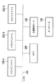
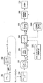
はじめに、本発明の一実施形態に係る画像処理システムについて、図1を用いて説明する。図1は、当該画像処理システムの概略構成を示すブロック図である。
[Image processing system]
First, an image processing system according to an embodiment of the present invention will be described with reference to FIG. FIG. 1 is a block diagram showing a schematic configuration of the image processing system.
本実施形態の画像処理システムは、LAN101上にMFP100、および単数または複数のクライアントPC102−1〜n(ホストコンピュータ)を接続した形態をとる。MFP100とクライアントPC102に加えて、本システムは文書管理サーバ103およびこのサーバに接続されて使用されるデータベース104も備えている。
The image processing system of the present embodiment takes a form in which the
本実施形態において、MFP100は紙の原稿をスキャンすることによってその原稿の画像データを生成する。また、クライアントPC102が生成するPDLデータを受信して、PDLデータの解釈やレンダリングを行う。また、画像データを、画像記録装置(プリンタ)113によって紙媒体上に記録したり、ネットワーク上に送信したり、あるいは、MFP100自身が持つ二次記憶装置からなる記憶部115に画像データを格納・記憶したりする。画像データを格納する手段は、ネットワーク上のデータベース104であっても構わない。その際には、MFP100は文書管理サーバ103と通信を行い、データベース104に画像データが格納されるように適宜制御する。
In the present embodiment, the
[MFP(画像処理装置)]
続いて、本発明の一実施形態であるMFP100の構成について、図2を用いて説明する。
[MFP (image processing device)]
Next, the configuration of the
図2は、MFP100の構成を示すブロック図である。
FIG. 2 is a block diagram showing a configuration of
MFP100は、図示しないAuto Document Feeder(以下、ADF)を有する画像読み取り装置110を備える。この画像読み取り部装置110は束状の或いは1枚の原稿の画像を光源で照射し、反射画像をレンズを介して固体撮像素子上に結像する。固体撮像素子は所定解像度(例えば600dpi)および所定輝度レベル(例えば8ビット階調)の画像読み取り信号を生成し、この画像読み取り信号から、ラスターデータよりなる画像データが構成される。画像読み取り装置110で読み取られた画像データは、読み取り画像処理部111によってMFP100内部で処理しやすい画像データに補正処理される。具体的には、読み取り画像処理部111は、ノイズ除去処理、ガンマ補正処理、色再現補正処理、フィルタ処理などを行う。
The MFP 100 includes an
MFP100は、記憶部115および画像記録装置113を有し、通常の複写機能を実行する際には、読み取り画像処理部111で処理された画像データに対し、さらに出力画像処理部112によって画像記録装置用の画像処理を行って、記録信号に変換する。複数枚複写する場合には、1頁分の記録信号を一旦記憶部115に記憶保持した後、画像記録装置113に順次出力して、記録紙上に記録画像を形成する。
The MFP 100 includes a
MFP100は、LAN101との接続のためのネットワークI/F114を有し、クライアントPC102からプリンタドライバを利用して出力するPDLデータを、画像記録装置113によって記録する機能を持つ。クライアントPC102からプリンタドライバを経由して出力されるPDLデータは、LAN101からネットワークI/F114を経て記憶部115の一部に保存される。保存されたPDLデータは取り出されて、ROM120あるいは記憶部115からRAM119にロードされたプログラムをCPU118が実行することによって実現される後述のPDL処理およびレンダリング処理によって、Bitmapデータとして展開される。そして、このBitmapデータに対し出力画像処理部112で、画像記録装置用の画像処理を行って記録可能な記録信号に変換する。この記録信号は、画像記録装置113に送出されて、記録紙上に記録画像として記録される。
The MFP 100 includes a network I /
また、記憶部115は、画像読み取り装置110からのデータやクライアントPC102からプリンタドライバを経由して出力される、PDLデータをレンダリングしたデータを保存できる機能(以下、この機能をBOX機能と称す)を有している。
In addition, the
MFP100は、MFP100を操作するためのユーザーインターフェースとして、入力装置116と表示装置117を備えている。表示装置117上には、MFP100の状態を表す情報やBOX機能により保存した画像データが表示される。また、表示装置117はタッチパネルを備え、表示装置117上に表示されたボタンをユーザーが触れることでユーザーの操作による指定入力を行うことができる。このほかのユーザー入力を受け付ける装置として、入力装置116は数値の入力を行うためのキーを備えている。
The
MFP100の上記構成要素は、CPU118で動作するRAM119上のプログラムによって、内部バス121を介して制御される。
The above components of the
[MFPの各機能の動作]
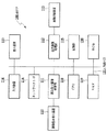
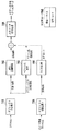
次に、本実施形態におけるMFPの持つ機能について、図3〜6を用いて説明する。図3は、MFP100のコピー機能・スキャン送信機能・BOX機能を実現する各処理ブロックによる処理の流れを示す図である。図4は、PDLデータに対するPDL処理機能・BOX機能について各処理ブロックによる処理の流れを示している。これらの機能は、一例として図5に示すUI画面500からのユーザー指示によって処理が開始される。
[Operation of each function of MFP]
Next, functions of the MFP according to the present embodiment will be described with reference to FIGS. FIG. 3 is a diagram showing the flow of processing by each processing block for realizing the copy function, scan transmission function, and BOX function of
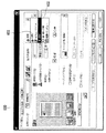
図5において、上部に位置するコピータブ504、送信FAXタブ503、BOXタブ501といった各機能別のタブによって、MFP100にどの機能を働かせるかをユーザーに選択させる。図面上では、BOXタブ501が選択されているので、この時に読み込みスタートボタン502を押下すると、MFP100はBOX格納を行うように制御する。他のタブにも502と同様にその機能を働かせるスタートボタンがあり、BOX機能の開始の場合と同様に、ボタン押下で該当する機能の処理をスタートするようにする。
In FIG. 5, the user selects which function is to be operated on the
MFP100は、コピー機能・スキャン送信機能・BOX機能のいずれの場合においても、画像読み取り装置110で紙の原稿を読み取り、画像データを得るように制御する。その次に読み取り画像処理部111でスキャン画像用の画像処理を行い、記憶部115の一部を用いて実現する一時的な画像データ保存領域であるBitmapスプール(レンダリングバッファ)201にBitmapデータを保存する。
In any case of the copy function, the scan transmission function, and the BOX function, the
コピー機能使用時は、Bitmapスプール201から取り出したBitampデータを出力画像処理部112で画像処理を行って記録信号に変換してから、画像記録装置113に出力するように制御する。
When the copy function is used, the Bitamp data taken out from the
スキャン送信機能においては、CPU118上で動作するプログラムによって実現される画像送信処理部202により、ネットワークI/F114を介して、UI上で指定されたIPアドレスを持つPC等の機器に対して、画像データを送るように制御する。
In the scan transmission function, an image
最後にBOX機能においては、Bitmapスプール201から取り出したBitmapデータを、CPU上で動作するプログラムによって実現される画像格納処理部200で処理したあと、記憶部115に記憶するようにする。ここで述べた画像格納処理については、後ほど詳細に説明を加える。
Finally, in the BOX function, the Bitmap data taken out from the
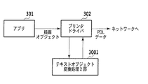
MFP100が持つPDL処理機能は、ユーザーがクライアントPC上のアプリケーション301でプリント指示を行うところから処理が始まる。図4に示すように、クライアントPC102上で動作するアプリケーション301から、プリンタドライバ302にアプリケーションデータが描画情報として渡される。このデータは、プリンタドライバ302でPostScriptやLIPSなどのPDL言語に従うデータ(PDLデータ)に変換されて、クライアントPC102のネットワークI/F(不図示)を介してネットワーク送信される。
The PDL processing function of the
MFP100はネットワークI/F114で受信したPDLデータを、PDLデータの一時保存領域であるPDLデータスプール303に保存する。いったんスプールされたPDLデータは取り出された後に、PDL処理部304によって言語解釈されて、レンダラ305が処理できる中間的なデータ構造であるDisplayListを生成する。レンダラ305は生成されたDisplayListをBitmapデータに展開して、Bitmapスプール201に一時保存する。
The
MFP100は、プリンタドライバ302の指示が印刷であれば、Bitmapスプール201から画像データを取り出した後に、出力画像処理部112による画像処理を行い、画像記録装置113に記録信号を送出して処理を終える。プリンタドライバの指示が画像データの保存である場合には、後述の画像格納処理200を行った後に、記憶部115に画像データを格納するようにする。
If the instruction of the
プリンタドライバの指示については、図6に示すように、保存を指定するUI項目602と印刷を指定するUI項目601によって、保存指示か、印刷指示かをユーザーに選択させる。
As shown in FIG. 6, the user instructs the user to select a save instruction or a print instruction by using a
[画像格納処理]
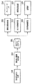
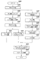
次に、画像格納処理について図7を用いて説明する。
[Image storage processing]
Next, image storage processing will be described with reference to FIG.
図7は、画像格納処理部200の構成を示すブロック図である。
FIG. 7 is a block diagram illustrating a configuration of the image
MFP100におけるUI500あるいはドライバUI600によって、文書の保存が指示された場合に、Bitmapスプール201から取り出した画像データをBOXに保存するために行う画像格納処理部の処理の流れの一例を図7に示す。
FIG. 7 shows an example of the processing flow of the image storage processing unit performed to save the image data extracted from the
MFP100は、Bitmapスプール201から取り出した画像データを、まず、オブジェクト分割処理部701によって、オブジェクトを含む領域毎に領域分割することによりオブジェクト分割を行う。
The
オブジェクト分割後のオブジェクトの種類は、文字、写真、グラフィック(図面、線画、表)、背景、である。このオブジェクト分割処理においては、ビットマップデータのままで、オブジェクト毎にそれを含むように画像領域分割を行い、分割された各々の画像領域に対して、周知の手法でオブジェクトの種類(文字、写真、グラフィック、背景)を判別する。 The types of objects after the object division are characters, photographs, graphics (drawings, line drawings, tables), and backgrounds. In this object division processing, image area division is performed so that each object is included with the bitmap data as it is, and for each divided image area, the object type (character, photograph, etc.) is used. , Graphics, background).
判別対象の画像領域が写真オブジェクトと判別された場合、この領域は、JPEG圧縮処理部702において、JPEG圧縮される。また、背景の場合も同様に、JPEG圧縮される。一方、オブジェクト判別の結果が、グラフィックの場合、ベクトル化処理部703において、ベクトル化処理され、パス化されたデータに変換される。また、オブジェクト判別の結果が、文字の場合には、ベクトル化処理部703において、グラフィックと同様にベクトル化処理され、パス化されたデータに変換される。それとともに、文字の場合には、OCR処理部704にも当該分割領域のBitmapデータが送られ、そのデータに対しOCR処理が施され、文字コード化されたデータが抽出される。これらの全てのオブジェクトデータと、文字コード化されたデータが一つのファイルとしてまとめられる。
When it is determined that the image area to be determined is a photographic object, the area is JPEG compressed by the JPEG
最後に、メタデータ付与処理部705において、各オブジェクトに対して、生成されたメタデータが付与される。このメタデータが付与された各々のオブジェクトデータは、MFP100に内蔵されているBOX115に保存される。ここで保存されたデータは、UI画面に表示するようにしてもよい。
Finally, in the metadata
以下では、メタデータ付与処理、オブジェクト分割処理、ベクトル化処理について、さらに詳細に説明する。 Hereinafter, the metadata adding process, the object dividing process, and the vectorization process will be described in more detail.
[メタデータ付与処理]
まず、メタデータ付与処理について、図8を用いて説明する。
[Metadata giving process]
First, the metadata providing process will be described with reference to FIG.
図8は、メタデータ付与処理部705で行うメタデータ付与処理のフローチャートである。
FIG. 8 is a flowchart of the metadata providing process performed by the metadata providing
まず、ステップS801において、メタデータを付与するオブジェクトの周囲で一番近くに存在する文字オブジェクトを選択する。 First, in step S801, a character object that is closest to the periphery of an object to which metadata is added is selected.
次に、ステップS802において、ステップS801で選択された文字オブジェクトに対して、形態素解析を行う。 Next, in step S802, morphological analysis is performed on the character object selected in step S801.
次いで、ステップS803において、ステップS802における形態素解析により抽出された単語をメタデータとして、これを対象のオブジェクトに付加する。なお、メタデータ付与対象のオブジェクトが文字オブジェクトの場合もあり、このときの、周囲で一番近くにあるオブジェクトは、この文字オブジェクト自身をも含む。すなわち、この場合、文字オブジェクトから抽出した単語がその文字オブジェクトのメタデータとして付与されることとなる。 In step S803, the word extracted by the morphological analysis in step S802 is added as metadata to the target object. Note that the object to which the metadata is applied may be a character object, and the object closest to the periphery at this time includes the character object itself. That is, in this case, a word extracted from the character object is given as metadata of the character object.
また、メタデータの作成には、形態素解析によって抽出した単語だけではなく、そのオブジェクトから抽出した色ヒストグラムなどの画像特徴量や、形態素解析だけでなく、より高度な構文解析等により得られる文章要約情報なども含めることが可能である。 In addition, not only words extracted by morphological analysis, but also image feature quantities such as color histograms extracted from the objects, and text summaries obtained not only by morphological analysis but also by more advanced syntax analysis are used for metadata creation. Information can also be included.
このようにして得られたメタデータは、オブジェクトの各々に対して記述されて、オブジェクトの画像データ(ベクトル化またはJPEG圧縮されたデータ)とともに、BOXに保存される。 The metadata obtained in this way is described for each object, and is stored in the BOX together with the image data (vectorized or JPEG compressed data) of the object.
[ベクトル化結果のデータフォーマット]
次に、ベクトル化処理部703でベクトル化されたデータのフォーマットについて、図9を用いて説明する。
[Data format of vectorization result]
Next, the format of data vectorized by the
図9は、ベクトル化処理部703でベクトル化されたデータのフォーマットの一例を示す図である。本実施形態では、ベクトル化処理部703でベクトル化されたデータをSVG形式で表記しているが、これに限定されるものではない。
FIG. 9 is a diagram illustrating an example of a format of data vectorized by the
図9では説明のために、オブジェクトの表記を枠で囲っている。枠:901はイメージ属性を示し、そこには、イメージオブジェクトの領域の示す領域情報とビットマップ情報が示されている。枠:902はテキストオブジェクトの情報が示されており、枠:903では、枠:902で示した内容、すなわちテキストオブジェクトの情報をベクターオブジェクトとして表現している。枠:904は、表オブジェクトなどのラインアートを表す。 In FIG. 9, the object notation is surrounded by a frame for explanation. A frame: 901 indicates an image attribute, in which area information and bitmap information indicating an area of the image object are displayed. A frame: 902 shows information on the text object, and a frame: 903 expresses the contents shown in the frame: 902, that is, information on the text object as a vector object. A frame: 904 represents line art such as a table object.
メタデータ付与処理部705で付与されるメタデータは、例えば、それが“山田 太郎”である場合、各ブロックの末尾に、以下の、
<metadata>
<text_index>山田 太郎</text_index>
</metadata>
のように付与すればよい。
For example, when the metadata given by the metadata
<metadata>
<text_index> Taro Yamada </ text_index>
</ metadata>
It may be given as follows.
[オブジェクト分割処理]
次に、オブジェクト分割処理について、図10、11を用いて説明する。
[Object division processing]
Next, the object division process will be described with reference to FIGS.
図10は、オブジェクト分割処理による画像データのオブジェクト分割結果の一例を示す図である。また、図11は、オブジェクト分割したときの各属性のブロック情報および入力ファイル情報の例を示す図である。 FIG. 10 is a diagram illustrating an example of an object division result of image data by the object division process. FIG. 11 is a diagram illustrating an example of block information and input file information of each attribute when the object is divided.
オブジェクト分割処理部701は、図10右側の画像1002に示すように、入力画像1001(図10左側)を属性ごとに矩形ブロックに分割する。前述のように、本実施形態においては、矩形ブロックの属性としては、文字、写真、グラフィック(図面、線画、表など)とするが、もちろん、これに限られるものではなく、色文字や黒文字、あるいは自然画像やCG画像などに細分化することも可能である。
As shown in an
オブジェクト分割処理においては、まず、Bitmapスプール201から取り出されてRAM上に格納されたイメージデータを白黒に2値化し、黒画素からなる輪郭で囲まれる画素塊を抽出する。
In the object division processing, first, the image data taken out from the
さらに、このように抽出された画素塊のうち黒画素塊の大きさを評価し、大きさが所定値以上の黒画素塊の内部にある白画素塊に対する輪郭追跡を行う。さらに、白画素塊に対する大きさ評価、およびその内部の黒画素塊の追跡というように、内部の画素塊の大きさが所定値以上である限り、再帰的に内部の画素塊の抽出、および輪郭追跡を行う。なお、画素塊の大きさは、例えば画素塊の面積によって評価される。 Further, the size of the black pixel block among the pixel blocks extracted in this way is evaluated, and contour tracking is performed for the white pixel block inside the black pixel block whose size is a predetermined value or more. Further, as long as the size of the internal pixel block is a predetermined value or more, such as size evaluation for the white pixel block and tracking of the black pixel block inside the white pixel block, the internal pixel block is extracted and contoured recursively. Do tracking. Note that the size of the pixel block is evaluated by, for example, the area of the pixel block.
このようにして得られた画素塊に外接する矩形ブロックを生成し、矩形ブロックの大きさ、および形状に基づき属性を判定する。 A rectangular block circumscribing the pixel block thus obtained is generated, and attributes are determined based on the size and shape of the rectangular block.
例えば、縦横比が1に近く、大きさが一定の範囲の矩形ブロックは文字領域矩形ブロックの可能性がある文字相当ブロックとする。そして、近接する文字相当ブロックが規則正しく整列しているときに、これら文字相当ブロックを纏めた新たな矩形ブロックを生成し、この新たな矩形ブロックを文字領域矩形ブロックとする。 For example, a rectangular block having an aspect ratio close to 1 and having a constant size is assumed to be a character equivalent block that may be a character area rectangular block. Then, when adjacent character-corresponding blocks are regularly arranged, a new rectangular block in which these character-corresponding blocks are collected is generated, and this new rectangular block is set as a character area rectangular block.
また扁平な画素塊、もしくは、一定大きさ以上でかつ四角形の白画素塊を整列した状態で内包する黒画素塊をグラフィック領域矩形ブロック、それ以外の不定形の画素塊を写真領域矩形ブロックとする。 In addition, a flat pixel block or a black pixel block that is larger than a certain size and includes square white pixel blocks arranged in a line is a graphic area rectangular block, and the other irregular pixel block is a photo area rectangular block. .
オブジェクト分割処理では、このようにして生成された矩形ブロックのそれぞれについて、図11に示す、属性等のブロック情報および入力ファイル情報を生成する。 In the object division processing, block information such as attributes and input file information shown in FIG. 11 are generated for each of the rectangular blocks generated in this way.
図11において、同図に示すブロック情報には、各ブロックの属性、その位置の座標X、座標Y、幅W、高さH、OCR情報が含まれる。属性は1〜3の数値で与えられ、ここで1は文字領域矩形ブロック、2は写真領域矩形ブロック、3はグラフィック領域矩形ブロックを示す。座標X、座標Yは入力画像における各矩形ブロックの始点のX、Y座標(左上角の座標)である。幅W、高さHは、それぞれ矩形ブロックのX座標方向の幅、Y座標方向の高さである。OCR情報は、各ブロックのメタデータとして使用可能なOCR結果があるか否かを示す。さらに入力ファイル情報として矩形ブロックの個数を示すブロック総数Nが含まれる。 In FIG. 11, the block information shown in FIG. 11 includes attributes of each block, coordinates X, coordinates Y, width W, height H, and OCR information of the position. The attribute is given by a numerical value of 1 to 3, where 1 is a character area rectangular block, 2 is a photo area rectangular block, and 3 is a graphic area rectangular block. The coordinates X and Y are the X and Y coordinates (upper left corner coordinates) of the start point of each rectangular block in the input image. The width W and the height H are the width of the rectangular block in the X coordinate direction and the height in the Y coordinate direction, respectively. The OCR information indicates whether there is an OCR result that can be used as metadata of each block. Furthermore, the total number N of blocks indicating the number of rectangular blocks is included as input file information.
これらの矩形ブロックごとのブロック情報は、特定領域でのベクトル化に利用される。またブロック情報によって、特定領域とその他の領域を合成する際の相対位置関係を特定でき、入力画像のレイアウトを損なわずにベクトル化領域とラスターデータ領域を合成することが可能となる。 The block information for each rectangular block is used for vectorization in a specific area. Further, the relative positional relationship when the specific area and other areas are combined can be specified by the block information, and the vectorized area and the raster data area can be combined without impairing the layout of the input image.
[ベクトル化処理]
次に、ベクトル化処理部703の処理について、図12を用いて説明する。
[Vectorization processing]
Next, processing of the
図12は、ベクトル化処理部703における処理の流れを示すフローチャートである。
FIG. 12 is a flowchart showing the flow of processing in the
はじめに、ステップS1201で、処理の対象となる特定領域が文字領域矩形ブロックであるか否かを判断する。このとき、特定領域が文字領域矩形ブロックであればステップS1202以下のステップに進み、以下に説明するようにパターンマッチングの一手法を用いて文字認識を行い、対応する文字コードを得る。一方、特定領域が文字領域矩形ブロックでない場合は、ステップS1212に移行する。 First, in step S1201, it is determined whether or not the specific area to be processed is a character area rectangular block. At this time, if the specific area is a character area rectangular block, the process proceeds to step S1202 and the subsequent steps, and character recognition is performed using one method of pattern matching as described below to obtain a corresponding character code. On the other hand, if the specific area is not a character area rectangular block, the process proceeds to step S1212.
ステップS1202では、特定領域に対し横書き、縦書きの判定(組み方向判定)をおこなうために、特定領域内で画素値に対する水平・垂直の射影を取る。 In step S1202, in order to perform horizontal writing and vertical writing determination (assembling direction determination) on the specific area, a horizontal / vertical projection is performed on the pixel value within the specific area.
次いで、ステップS1203で、ステップS1202の射影の分散を評価する。水平射影の分散が大きい場合は横書き、垂直射影の分散が大きい場合は縦書きと判断する。 Next, in step S1203, the projection variance in step S1202 is evaluated. If the horizontal projection variance is large, it is determined as horizontal writing, and if the vertical projection variance is large, it is determined as vertical writing.
次に、ステップS1204で、ステップS1203での評価結果に基づき、組み方向を判定し、組み方向に応じた行の切り出しを行う。さらに、切出した行から文字を切り出して文字画像を得る。文字列および文字への分解は、横書きならば水平方向の射影を利用して行を切り出し、切り出された行に対する垂直方向の射影を基に、文字を切り出す。縦書きの文字領域に対しては、水平方向と垂直方向について、逆の処理を行う。ここでの行、文字の切り出しに際して、文字のサイズも検出し得る。 Next, in step S1204, based on the evaluation result in step S1203, the assembling direction is determined, and lines corresponding to the assembling direction are cut out. Further, a character image is obtained by cutting out characters from the cut out line. In the case of horizontal writing, character strings and characters are segmented using a horizontal projection, and a character is segmented based on a projection in the vertical direction with respect to the segmented line. For vertically written character areas, the opposite process is performed in the horizontal and vertical directions. The character size can also be detected when the line or character is cut out here.
次に、ステップS1205では、ステップS1204で切り出された各文字について、文字画像から得られる特徴量を数十次元の数値列に変換した特徴ベクトル(ここでは、観測特徴ベクトルと称す)を生成する。この観測特徴ベクトルの抽出には種々の公知手法があり、例えば、文字をメッシュ状に分割し、各メッシュ内の文字線を方向別に線素としてカウントしたメッシュ数次元ベクトルを特徴ベクトルとする方法がある。上記観測特徴ベクトルは、このような周知の手法を用いて生成可能である。 Next, in step S1205, for each character extracted in step S1204, a feature vector (herein referred to as an observed feature vector) is generated by converting the feature quantity obtained from the character image into a tens-dimensional numerical string. There are various known methods for extracting the observed feature vector. For example, there is a method in which a character is divided into meshes, and a mesh number-dimensional vector obtained by counting character lines in each mesh as line elements according to directions is used as a feature vector. is there. The observed feature vector can be generated using such a known method.
次に、ステップS1206で、ステップS1205で得られた観測特徴ベクトルと、あらかじめフォントの種類ごとに求められている辞書特徴ベクトルとを比較し、観測特徴ベクトルと辞書特徴ベクトルとの距離を算出する。 Next, in step S1206, the observation feature vector obtained in step S1205 is compared with the dictionary feature vector obtained in advance for each font type, and the distance between the observation feature vector and the dictionary feature vector is calculated.
次いで、ステップS1207において、ステップS1206で算出された距離を評価し、最も距離の近いフォントの種類を、その文字の認識結果とする。 Next, in step S1207, the distance calculated in step S1206 is evaluated, and the font type with the closest distance is set as the recognition result of the character.
次に、ステップS1208では、ステップS1207における距離評価において、最短距離が所定値よりも大きいか否かにより、類似度を判断する。最短距離が所定値以上の場合は、辞書特徴ベクトルにおいて、形状が類似する他の文字に誤認識している可能性が高い。そこで上記最短距離が所定値以上の場合は、ステップS1207の認識結果を採用せず、ステップS1211の処理に進む。一方、上記最短距離が所定値より低い(小さい)ときは、ステップS1207の認識結果を採用し、ステップ1209に進む。 Next, in step S1208, the similarity is determined based on whether or not the shortest distance is larger than a predetermined value in the distance evaluation in step S1207. When the shortest distance is greater than or equal to a predetermined value, there is a high possibility that the dictionary feature vector is erroneously recognized as another character having a similar shape. Therefore, if the shortest distance is equal to or greater than the predetermined value, the recognition result in step S1207 is not adopted, and the process proceeds to step S1211. On the other hand, when the shortest distance is lower (smaller) than the predetermined value, the recognition result of step S1207 is adopted, and the process proceeds to step 1209.
ステップS1209(フォント認識ステップ)では、文字フォントの認識処理を行う。本実施形態では、文字認識の際に用いる、フォントの種類数分の辞書特徴ベクトルを、文字形状種すなわちフォント種に対して複数用意しておく。そして、パターンマッチングの際に、文字コードとともにフォント情報としてマッチするフォント種を出力することで、文字フォントを認識し得る。 In step S1209 (font recognition step), character font recognition processing is performed. In this embodiment, a plurality of dictionary feature vectors corresponding to the number of font types used for character recognition are prepared for the character shape type, that is, the font type. Then, at the time of pattern matching, the character font can be recognized by outputting the font type that matches with the character code as the font information.
次いでステップS1210では、上記文字認識およびフォント認識よって得られた文字コードおよびフォント情報と、あらかじめ用意された対応するアウトラインデータを用いて、各文字をベクトルデータに変換する。なお、入力画像がカラーの場合は、カラー画像から各文字の色を抽出して、得られた色情報をベクトルデータとともに記録する。 In step S1210, each character is converted to vector data using the character code and font information obtained by the character recognition and font recognition and corresponding outline data prepared in advance. When the input image is color, the color of each character is extracted from the color image, and the obtained color information is recorded together with vector data.
ステップS1211では、文字を一般的なグラフィックと同様に扱い、該当文字をアウトライン化する。すなわち誤認識を起こす可能性の高い文字については、可視的にイメージデータに忠実なアウトラインのベクトルデータを生成する。 In step S1211, characters are handled in the same way as general graphics, and the corresponding characters are outlined. In other words, outline vector data that is visually faithful to the image data is generated for characters that are likely to cause erroneous recognition.
ステップS1212では、特定領域が文字領域矩形ブロックでないとき、画像の輪郭に基づいてベクトル化の処理を実行する。 In step S1212, when the specific area is not a character area rectangular block, vectorization processing is executed based on the contour of the image.
以上の処理により、文字領域矩形ブロックに属するイメージ情報を、形状、大きさ、色についてほぼ忠実なベクトルデータに変換出来る。 Through the above processing, the image information belonging to the character area rectangular block can be converted into vector data that is almost faithful in shape, size, and color.
[グラフィック領域のベクトル化]
次に、グラフィック領域のベクトル化について、図13、14を用いて説明する。
[Vectorization of graphic area]
Next, vectorization of the graphic area will be described with reference to FIGS.
図13は、ベクトル化の処理における角抽出の処理を説明するための図であり、図14は、ベクトル化の処理における輪郭線まとめの処理を説明するための図である。 FIG. 13 is a diagram for explaining the corner extraction process in the vectorization process, and FIG. 14 is a diagram for explaining the outline grouping process in the vectorization process.
オブジェクト分割処理において、特定領域が、文字領域矩形ブロック以外の領域、すなわちグラフィック領域矩形ブロックと判断されたときは、特定領域内で抽出された黒画素塊の輪郭をベクトルデータに変換する。 In the object division processing, when the specific area is determined to be an area other than the character area rectangular block, that is, the graphic area rectangular block, the outline of the black pixel block extracted in the specific area is converted into vector data.
文字領域以外の領域のベクトル化においては、まず線画等を直線および/または曲線の組み合わせとして表現するために、曲線を複数の区間(画素列)に区切る「角」を検出する。「角」とは曲率が極大となる点である。例えば、図13の曲線上の画素Piが「角」か否かの判断は以下のように行う。 In vectorization of regions other than character regions, first, “corners” that divide a curve into a plurality of sections (pixel columns) are detected in order to represent a line drawing or the like as a combination of straight lines and / or curves. The “corner” is the point where the curvature is maximized. For example, whether the pixel Pi on the curve in FIG. 13 is a “corner” is determined as follows.
すなわち、Piを起点とし、曲線に沿ってPiから両方向に所定画素(k個とする)ずつ離れた画素Pi−k、Pi+kを線分Lで結ぶ。画素Pi−k、Pi+k間の距離をd1、線分Lと画素Piとの距離をd2、曲線の画素Pi−k、Pi+k間の弧の長さをAとする。d2が極大となるとき、あるいは比(d1/A)が閾値以下となるときに画素Piを「角」と判断する。 That is, pixels Pi-k and Pi + k that are separated from Pi by both predetermined pixels (k pixels) in both directions along the curve are connected by a line segment L starting from Pi. The distance between the pixels Pi-k and Pi + k is d1, the distance between the line segment L and the pixel Pi is d2, and the arc length between the curved pixels Pi-k and Pi + k is A. When d2 becomes a maximum, or when the ratio (d1 / A) is equal to or less than the threshold, the pixel Pi is determined to be a “corner”.
「角」によって分割された画素列を、直線あるいは曲線で近似する。直線への近似は最小二乗法等により実行し、曲線への近似は3次スプライン関数などを用いる。画素列を分割する「角」の画素は近似直線あるいは近似直線における、始端または終端となる。 A pixel row divided by “corners” is approximated by a straight line or a curve. The approximation to a straight line is executed by the least square method or the like, and the approximation to a curve uses a cubic spline function or the like. The “corner” pixel that divides the pixel row is the start or end of the approximate line or the approximate line.
さらにベクトル化された輪郭内に白画素塊の内輪郭が存在するか否かを判断し、内輪郭が存在するときはその輪郭をベクトル化し、その内輪郭の内輪郭というように、再帰的に反転画素の内輪郭をベクトル化する。 Further, it is determined whether or not the inner contour of the white pixel block exists in the vectorized contour, and if there is an inner contour, the contour is vectorized, and the inner contour of the inner contour is recursively. The inner contour of the inverted pixel is vectorized.
以上のように、輪郭の区分線近似を用いれば、任意形状の図形のアウトラインをベクトル化することができる。元原稿がカラーの場合は、カラー画像から図形の色を抽出して、得られた色情報をベクトルデータとともに記録する。 As described above, the outline of a figure having an arbitrary shape can be vectorized by using the contour line approximation. When the original document is color, the color of the figure is extracted from the color image, and the obtained color information is recorded together with vector data.
図14に示すように、ある注目区間で外輪郭PRjと、内輪郭PRj+1あるいは別の外輪郭が近接している場合、2つあるいは複数の輪郭線をひとまとめにし、太さを持った線として表現することができる。例えば、輪郭PRj+1の各画素Piから輪郭PRj上で最短距離となる画素Qiまでの距離PQiを算出し、PQiのばらつきがわずかである場合には、注目区間を画素Pi、Qiの中点Miの点列に沿った直線または曲線で近似し得る。近似直線、近似曲線の太さは、例えば距離PQiの平均値とする。線や線の集合体である表罫線は、太さを持つ線の集合とすることにより、効率よくベクトル表現することができる。 As shown in FIG. 14, when an outer contour PRj and an inner contour PRj + 1 or another outer contour are close to each other in a certain attention section, two or a plurality of contour lines are combined and expressed as a line having a thickness. can do. For example, the distance PQi from each pixel Pi of the contour PRj + 1 to the pixel Qi that is the shortest distance on the contour PRj is calculated, and when the variation in PQi is slight, the attention interval is set to the midpoint Mi of the pixels Pi and Qi It can be approximated by a straight line or curve along the point sequence. The thickness of the approximate line and the approximate curve is, for example, an average value of the distance PQi. A table ruled line, which is a line or a set of lines, can be efficiently expressed as a vector by using a set of lines having a thickness.
輪郭線まとめの処理の後、ベクトル化全体の処理を終了する。なお写真領域矩形ブロックについては、ベクトル化せず、イメージデータのままとする。 After the outline summarization process, the entire vectorization process ends. Note that the photographic area rectangular block is not vectorized and remains as image data.
[ベクトルデータのグループ化]
次に、ベクトルデータのグループ化について、図15を用いて説明する。
[Vector data grouping]
Next, vector data grouping will be described with reference to FIG.
図15は、図12を用いて説明したベクトル化処理により生成されたベクトルデータのグループ化の処理を示すフローチャートである。 FIG. 15 is a flowchart illustrating grouping processing of vector data generated by the vectorization processing described with reference to FIG.
ベクトル化処理により線図形等のアウトラインをベクトル化した後、ベクトル化された区分線を図形オブジェクトごとにグループ化する。 After the outline of a line figure or the like is vectorized by vectorization processing, the vectorized dividing lines are grouped for each graphic object.
はじめに、ステップS1501で、各ベクトルデータの始点、終点を算出する。 First, in step S1501, the start point and end point of each vector data are calculated.
次いで、ステップS1502(図形要素検出)において、ステップS1201で求められた始点、終点情報を用いて、図形要素を検出する。ここで図形要素とは、区分線が構成している閉図形であり、検出に際しては、始点、終端となっている共通の「角」の画素においてベクトルを連結する。すなわち、閉形状を構成する各ベクトルはその両端にそれぞれ連結するベクトルを有しているという原理を応用する。 Next, in step S1502 (graphic element detection), a graphic element is detected using the start point and end point information obtained in step S1201. Here, the graphic element is a closed graphic formed by a dividing line. For detection, a vector is connected at a common “corner” pixel at the start point and the end point. That is, the principle that each vector constituting the closed shape has a vector connected to both ends thereof is applied.
次いで、ステップS1503において、次に図形要素内に存在する他の図形要素、もしくは区分線をグループ化し、一つの図形オブジェクトとする。また、図形要素内に他の図形要素、区分線が存在しない場合はその図形要素自体を図形オブジェクトとする。 Next, in step S1503, other graphic elements or dividing lines that are present in the graphic element next are grouped into one graphic object. If there is no other graphic element or dividing line in the graphic element, the graphic element itself is set as a graphic object.
[図形要素の検出]
次に図形要素の検出処理について、図16を用いて説明する。
[Detection of graphic elements]
Next, graphic element detection processing will be described with reference to FIG.
図16は、図15を用いて説明したベクトルデータのグループ化の処理でグループ化されたベクトルデータに対する図形要素検出の処理を示すフローチャートである。 FIG. 16 is a flowchart showing graphic element detection processing for vector data grouped in the vector data grouping processing described with reference to FIG.
前述のステップS1502(図形要素検出)の処理は、図16の各ステップによって実行される。 The above-described processing of step S1502 (graphic element detection) is executed by each step of FIG.
はじめに、ステップS1601において、ベクトルデータから両端に連結していない不要なベクトルを除去し、閉図形を構成するベクトルを抽出する。 First, in step S1601, unnecessary vectors that are not connected to both ends are removed from vector data, and a vector constituting a closed figure is extracted.
次に、ステップS1602で、閉図形を構成するベクトルについて、いずれかのベクトルの端点(始点または終点)を開始点とし、一定方向、例えば時計回りに、順にベクトルを探索する。すなわち、他端点において他のベクトルの端点を探索し、所定距離内の最近接端点を連結ベクトルの端点とする。閉図形を構成するベクトルを1まわりして開始点に戻ったとき、通過したベクトルを全て一つの図形要素を構成する閉図形としてグループ化する。また、閉図形内部にある閉図形構成ベクトルも全てグループ化する。さらにまだグループ化されていないベクトルの始点を開始点とし、同様の処理を繰り返す。 Next, in step S1602, for the vectors constituting the closed figure, the vectors are searched in order in a certain direction, for example, clockwise, starting from the end point (start point or end point) of any vector. That is, the end point of another vector is searched at the other end point, and the closest end point within a predetermined distance is set as the end point of the connected vector. When the vector constituting the closed figure is rotated by one and returned to the starting point, all the passed vectors are grouped as a closed figure constituting one graphic element. In addition, all closed graphic constituent vectors inside the closed graphic are also grouped. Further, the same processing is repeated with the starting point of a vector not yet grouped as a starting point.
最後に、ステップS1603において、ステップS1601で除去された不要ベクトルのうち、ステップS1602で閉図形としてグループ化されたベクトルに端点が近接しているベクトルを検出し、これも一つの図形要素としてグループ化する。 Finally, in step S1603, among the unnecessary vectors removed in step S1601, a vector whose end point is close to the vector grouped as a closed figure in step S1602 is detected, and this is also grouped as one figure element. To do.
以上の処理によって図形要素を、再利用可能な個別の図形オブジェクトとして扱う事が可能になる。 With the above processing, a graphic element can be handled as a reusable individual graphic object.
[表示方法]
MFP100は、BOXに保存した文書を、その確認のため、あるいは、検索などの操作のために、表示装置117により表示し、入力装置116などによって操作することができる。以下、このような操作のためのUI表示に関して図17〜21を用いて詳細な説明を行う。
[Display method]
The
図17〜21は、それぞれ、本実施形態におけるユーザーインターフェースの一表示形態を示す図である。 17 to 21 are diagrams showing one display form of the user interface in the present embodiment, respectively.
図17は、特に、BOX内に保存されているデータの一覧(BOX文章一覧1701)をUI上に表示したものを示している。同図1702に示すように一つ一つの文章に名前がついており、入力された時間などの情報も表示される。オブジェクト分割表示を行う場合には、1701のBOX文章一覧で所望の文章を選択して、オブジェクト表示ボタン1703を押すことで表示が変わり、オブジェクト分割表示を行うことができる。これに関しては、後述する。また、1701のBOX文章一覧で原稿を選択して、ページ表示ボタン1704を押すことで表示を変えることができるが、これに関しても後述する。
FIG. 17 particularly shows a list of data stored in the BOX (BOX text list 1701) displayed on the UI. As shown in FIG. 1702, each sentence has a name, and information such as the input time is also displayed. When the object division display is performed, the display is changed by selecting a desired sentence from the
図18は、特に、保存された原稿のデータに基づいて原稿の画像をUI上のページ表示画面1801に表示したものを示している。ここでは、原稿のラスタ画像を縮小した画像を表示することや、前述したSVGを使って表示をさせる事も可能である。つまり、前述してきたデータを基にページ全体を表示していれば良い。1802は、MFP100がもつ機能を選択するためのタブで、コピーや送信(FAX)、リモート操作、ブラウジング、BOXといったMFP100が持っている機能を選択できるものである。これ以外の機能に対しても同様の表示を行うことが出来ることは示すまでもない。
FIG. 18 particularly shows that a document image is displayed on the
同図の1803により、原稿を読み取る場合の各種原稿モードを選択することが出来る。これは原稿タイプによって、画像処理を切り替えるために選択をするものであり、ここに示した以外のモードも同様に表示選択をする事が出来る。1804に示す読み込みスタートボタンにより、スキャナーが動作して、原稿の画像を読み込むことになる。この例では、読込みスタートボタンをUIの画面内に設けているが、別途設けられたスタートボタンの押下によって原稿読み込みを開始してもよい。
Various document modes for reading a document can be selected by 1803 in FIG. This is a selection for switching the image processing depending on the document type, and display modes can be selected in modes other than those shown here as well. A scanner is operated by a reading
図19は、オブジェクト分割した結果が分かるように原稿内の各オブジェクトに枠を付けて表示させるようにしたものである。同図1901のオブジェクト表示ボタンを押すことにより、ページ表示画面1902に対してそれぞれオブジェクトの枠が表示される。このとき、枠に色付けをすることにより、オブジェクトの違いを分かるように表示することや、線の太さ、あるいは、点線、破線の違いなどにより、オブジェクトの違いを分かるように表示を行う。ここでオブジェクトの種類としては、前述したように文字、図面、線画、表、写真等である。
FIG. 19 shows each object in the document with a frame so that the result of the object division can be seen. By pressing an object display button in FIG. 1901, an object frame is displayed on the
同図の1903は検索を行うための文字を入力する表示部分である。ここに検索文字列を入力して、検索を行うことで、検索対象のオブジェクトあるいはオブジェクトが含まれるページが検索される。検索方法に関しては、前述したオブジェクトに付与されたメタデータを利用し、周知の検索手法を用いることで、オブジェクトあるいはページの検索を行うことができる。また、検索されたオブジェクトあるいはページは、UI上に表示される。
In the figure,
図20は、オブジェクト表示ボタン2002を押すことによりページ内のオブジェクトが表示されるものである。ここでのオブジェクトの表示は、ページという概念ではなく、2001に示されるように一つ一つのオブジェクトが部品として表示される。また、ページ表示ボタン2004を押すことで1ページの画像として見えるように表示することもできる。
In FIG. 20, an object in a page is displayed by pressing an
同図の2003は検索を行うための検索文字列を入力する表示部分である。ここに検索文字列を入力して、検索を行うことで、検索対象のオブジェクトあるいはオブジェクトが含まれるページが検索される。検索方法に関しては、前述したオブジェクトに付与されたメタデータを利用し、周知の検索手法を用いることで、オブジェクトあるいはページの検索を行うことができる。また検索されたオブジェクトあるいはページは、UI上に表示される。
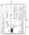
図21は、オブジェクトのメタデータをUI上に表示する例である。ある一つのオブジェクトを選択すると、2101に示すように、そのオブジェクトの画像2103と前述したメタデータ2102が表示される。ここで表示されるメタデータには、エリアの情報、幅、高さ、ユーザー情報、MFP100の設置場所の情報、入力した時間などの情報が含まれている。
FIG. 21 is an example of displaying object metadata on the UI. When one object is selected, an
この例では、選択されたオブジェクトがpicture(写真)属性のオブジェクトであり、このオブジェクトの近くにあった文字オブジェクトの文字認識結果から形態素解析を用いて名詞のみを取り出して表示を行っている。それが図示したTEXTという文字列にあたる。また、メタデータに対しては、2104に示すように、ボタン操作により、編集や追加、削除を行うことを可能としている。 In this example, the selected object is an object having a picture (photo) attribute, and only the noun is extracted from the character recognition result of the character object near the object by using morphological analysis and displayed. This corresponds to the character string TEXT shown in the figure. Further, as shown in 2104, the metadata can be edited, added, or deleted by a button operation.
同図に示す2105は検索を行うための文字を入力する表示部分である。ここに検索文字列を入力して、検索を行うことで、検索対象のオブジェクトあるいはオブジェクトが含まれるページが検索される。検索方法に関しては、前述したオブジェクトに付与されたメタデータを利用し、周知の検索手法を用いることで、オブジェクトあるいはページの検索を行うことができる。また検索されたオブジェクトあるいはページは、UI上に表示される。
以上、述べてきたように、画像読み取り装置で読み取った画像データだけでなく、PDLデータをラスタライズした画像データも同様に、オブジェクト分割処理とベクトル化処理およびOCR処理を行っている。これにより、OCR処理結果をもとにしたメタデータを生成するので、保存する文書データのフォーマットが統一できる。また同時に、PDLデータ中のテキストオブジェクトから文字コードを抽出してメタデータとして使用しようとする場合に生じる、以下の問題を解決することができる。すなわち、
・見た目はテキストデータであるにも係わらず、内部で保持しているデータとしては、Pathデータやイメージデータである場合に文字コードが得られない、
・文字コードだけでは意味が不明なものが得られてしまう、
・もとのテキストの文字列が一文字一文字に分割されて描画コマンドになっている場合には、文字認識後の形態素解析で有意なテキストデータが得られない、
といった問題を解決することができる。
As described above, object division processing, vectorization processing, and OCR processing are performed not only on image data read by the image reading apparatus but also on image data obtained by rasterizing PDL data. As a result, metadata based on the OCR processing result is generated, so that the format of the document data to be stored can be unified. At the same time, it is possible to solve the following problems that occur when a character code is extracted from a text object in PDL data and used as metadata. That is,
・ In spite of the fact that it is text data, it is not possible to obtain a character code when it is Path data or image data as data held internally.
・ Understanding the meaning only with the character code,
・ If the original text string is divided into one character and one character, and it is a drawing command, significant text data cannot be obtained by morphological analysis after character recognition.
Can be solved.
<第二の実施形態>
上述の第一の実施形態では、PDLデータがBOXに保存される際に、通常のレンダリングが行われて、そのレンダリング結果をOCR処理する例を説明した。
<Second Embodiment>
In the first embodiment described above, an example has been described in which normal rendering is performed when the PDL data is stored in the BOX, and the rendering result is subjected to OCR processing.
この処理の際、文字データに対して、特別な文字修飾や特別なフォントが使用されていた場合には、OCR処理の文字認識精度が不充分となる場合が考えられる。そこで本実施形態においては、特にPDLデータのBOX保存に関して、さらにOCR処理の精度を高めるために、OCR処理専用のレンダリングを行う例を説明する。 In this process, if a special character modification or a special font is used for the character data, the character recognition accuracy of the OCR process may be insufficient. Therefore, in the present embodiment, an example will be described in which rendering dedicated to OCR processing is performed in order to further improve the accuracy of OCR processing, particularly regarding BOX storage of PDL data.
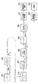
本実施形態においては、MFP100はドライバUI600でPDLデータに対するBOX保存を指示された際に図22に示す各処理ブロックによる処理の流れに従って動作するようにする。
In the present embodiment, when the
図22に示すように、PDL処理部304は、テキストオブジェクト変換処理部2201をさらに備えている。レンダラ305は、通常のレンダリングを行ってBitmapスプール201に画像を保存するパスとともに、OCR処理専用のレンダリングを行ってOCR専用Bitmapスプール2202に画像データを保存する構成をさらに備える。その他の処理ブロックは第一の実施形態において図4を用いて説明したとおりである。ただし、本実施形態においては、画像格納処理部200の構成、および、全体の処理フローが前述の第一の実施形態とは異なっている。
As illustrated in FIG. 22, the
以下、図23と図24を用いて、本実施形態における画像格納処理部200の詳細な構成と、画像データ格納処理における処理フローについて説明する。
Hereinafter, the detailed configuration of the image
図23は、本実施形態における画像格納処理部200の構成を示すブロック図であり、図24は、PDLデータ保存処理の処理フローを示すフローチャートである。
FIG. 23 is a block diagram illustrating a configuration of the image
画像格納処理部200において、図23に示すように、706のオブジェクト分割処理2部は、OCR専用Bitmapスプール2202からの出力を直接受けつける。ここでの処理は、オブジェクト分割処理部701と同様の処理を行えばよいが、特に、文字画像ブロックのみを抽出する処理を行う。オブジェクト分割処理2部706で判別された文字画像ブロックは、OCR処理部704において、第一の実施形態の場合と同様の処理を行い、文字コード情報を抽出する。
In the image
オブジェクト分割処理部701でも、第一の実施形態と同様にオブジェクト分割を行うが、本実施形態においては、文字ブロックの情報および画像データは、ベクトル化処理部703でのみ処理されるものとなる。各オブジェクトごとに、JPEG圧縮処理部702、ベクトル化処理部703、OCR処理部704による処理が行われた結果は統合されて、メタデータ付与処理部705に入力されメタデータが付与されて、BOX保存される。
The object
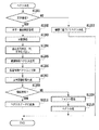
続いて、これら処理ブロックによって、BOX保存を行う際の処理フローの例を図24のフローチャートに示し、さらに詳細を説明する。 Subsequently, an example of a processing flow when performing BOX storage using these processing blocks is shown in the flowchart of FIG. 24, and further details will be described.
MFP100はクライアントPC102上で、ドライバUI600の指示に従って、PDLデータのBOX保存指示を受けて処理を開始する(S2400)。
In response to an instruction from the
ステップS2401でPDLデータをネットワークI/F114を介して受信して、PDLデータスプール303にデータを保存する。
In step S2401, the PDL data is received via the network I /
続いて、保存したデータを取り出して、ステップS2402においてPDL処理部304およびレンダリング部305の処理ブロックによる処理を行う。
Subsequently, the stored data is extracted, and processing by the processing blocks of the
続いて、ステップS2403において、処理後のBitmapデータをBitmapスプール201に保存する。この後、画像格納処理部200に処理を移す。すなわち、ステップS2404において、Bitmapデータを701のオブジェクト分割処理部により、オブジェクト分割する。
In
さらに、ステップS2405において、Bitmapデータのイメージ部分をJPEG圧縮すると同時に、ステップS3206で、グラフィックス部分および文字部分に対するベクトル化処理部703による処理を実行させる。
In step S2405, the image portion of the Bitmap data is JPEG-compressed. At the same time, in step S3206, the
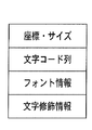
他方において、PDLデータに対してテキストオブジェクト変換処理部2201による処理を実行させる。本実施形態において、テキストオブジェクトは図25に示すような表現がなされており、オブジェクトの座標・サイズ、文字コード列、フォント情報、および、文字修飾情報からなっている。
On the other hand, processing by the text object
テキストオブジェクト変換処理部2201では、フォント情報すなわちフォント種別とフォントサイズをOCR処理が得意とするものに統一化して置き換える処理を行う。このことにより、OCR処理が扱わなければならない多種のフォントを一つに統一し、従って、フォントが多種であることによって低下する可能性のあるOCR処理精度を高めることができる。また、テキストオブジェクト変換処理部2201は、イタリック体やボールド体のような文字修飾情報を全て破棄するように動作する。このことによって、OCR処理が多種の字体修飾を処理しなければならないことによるOCR認識精度の低下を防ぐことが可能となる。
The text object
さらに付け加えれば、テキストオブジェクト変換処理部2201で変換されたPDLデータはOCR処理のためだけに使用され、画像記録装置113により記録される画像やUI画面に表示される画像には影響を与えない。従って、これらの出力は、図26に示すように、変換前の全く見え方の異なる文字要素となる。2601のようにサイズが大きすぎてOCRによる文字認識が成功しにくいもの、あるいは、パスデータとして処理してしまう可能性のあるものは、予め文字のサイズを小さくすることにより、OCR処理の文字認識率を向上させることができる。
In addition, the PDL data converted by the text object
また、2602のように、フォントや文字修飾や回転がかかっていてOCR処理により文字認識が成功しにくいものや、あるいは、イメージデータとして処理してしまう可能性のあるものが存在する。このような文字に対しては、予め文字修飾情報を破棄したり、フォントの文字種およびサイズを統一化することでOCR処理の文字認識率を向上させることができる。 In addition, there are fonts, character modifications, and rotations such as 2602 that make it difficult for character recognition to succeed by OCR processing, or data that may be processed as image data. For such characters, the character recognition rate of the OCR process can be improved by discarding the character modification information in advance or unifying the font type and size.
また、2603のように、文字コードとフォントの組み合わせでレンダリングされて初めて意味のある視覚情報となるようなオブジェクトは、フォントを統一することで、文字コードが言語情報として意味のないものであることが分かることになる。このようにすれば、OCR処理結果をもとにメタデータ付与する際の形態素解析において、不明語として処理されることにより、意味のないメタデータが付与されることを防ぐことができる。 In addition, an object that becomes meaningful visual information only after rendering with a combination of a character code and a font, such as 2603, has a meaningless character code as language information by unifying the font. Will be understood. In this way, it is possible to prevent meaningless metadata from being added by processing as an unknown word in the morphological analysis when assigning metadata based on the OCR processing result.
以上のようにして変換されたPDLデータは、ステップS2408でPDL処理およびレンダリングがなされる。 The PDL data converted as described above is subjected to PDL processing and rendering in step S2408.
そして、生成されたBitmapデータを、ステップS2409において、OCR専用Bitmapスプール2202に保存する。
The generated bitmap data is stored in the OCR
ステップS2411において、OCR処理部704はOCR専用Bitmapスプール2202からデータを取り出してOCR処理を行い、文字コードを出力する。
In step S2411, the
ステップS2412では文字コード情報とベクトル化されたデータの統合を行う。そして、ステップS3213においてメタデータ付与処理を行ってBOXへの保存を行う。 In step S2412, the character code information and vectorized data are integrated. In step S3213, metadata is added and saved in the BOX.
以上の処理を行って、全体の処理を終える(S2414)。 The above process is performed, and the entire process is completed (S2414).
通常BitmapのレンダリングとOCR専用Bitmapのレンダリングの実行タイミングについては、本実施形態での処理フローではほぼ同時であるものとする。しかし、2つのBitmapスプールにそれぞれ画像データを保持することができるので、このタイミングは同時でなくてもかまわない。例えば、OCR専用Bitmapデータをレンダリングにより作成し保存しておき、MFP100のCPUによる処理が空いた時間帯にそのOCR処理および画像格納処理を行うように待機させる制御を行っても構わない。
It is assumed that the execution timing of normal bitmap rendering and OCR dedicated bitmap rendering is almost the same in the processing flow of the present embodiment. However, since the image data can be held in the two Bitmap spools, this timing need not be the same. For example, OCR dedicated bitmap data may be created and stored by rendering, and control may be performed so that the OCR processing and image storage processing are performed in a time zone when processing by the CPU of the
<第三の実施形態>
前述の第一の実施形態および第二の実施形態においては、文字コード情報としてOCR処理の結果から得られるものを使用してメタデータの付与を行う例を説明した。特に第二の実施形態においては文字認識精度を高めるべく、OCR専用のBitmapデータを生成する構成を説明した。本実施形態においては、OCR処理によって得られた文字コード情報と、PDLデータからそのまま抽出される文字コード情報を併用して文字コード情報の信頼性を高める例を図27から29を用いて説明する。
<Third embodiment>
In the first embodiment and the second embodiment described above, an example in which metadata is given using character code information obtained from the result of OCR processing has been described. In particular, in the second embodiment, the configuration for generating Bitmap data dedicated to OCR has been described in order to improve character recognition accuracy. In the present embodiment, an example in which the character code information obtained by the OCR process and the character code information extracted from the PDL data as it is to increase the reliability of the character code information will be described with reference to FIGS. .
図27は、本実施形態におけるPDLデータに対するBOX保存処理の際の各処理ブロックによる処理の流れを示す図である。図28は、同実施形態における画像格納処理部200の構成を示す図であり、図29は、文字コード情報統合処理部707が行う処理フローの例を示すフローチャートである。
FIG. 27 is a diagram showing the flow of processing by each processing block at the time of BOX saving processing for PDL data in this embodiment. FIG. 28 is a diagram illustrating a configuration of the image
本実施形態においては、図27に示すように、レンダラ305に渡されるディスプレイリスト(Display List)情報から、文字コードを抽出する処理を行う文字コード情報抽出処理部2701を追加する。本実施形態の文字コード情報抽出処理部2701は、図25に示したテキストオブジェクト情報から座標・サイズ情報と文字コード情報を抽出し、画像格納処理部200に渡すように処理を行う。図27に示すその他の処理ブロックは、第二の実施形態で説明に用いた図22に示した対応する処理ブロックと同様のものとするが、第一の実施形態で説明に用いた図7に示した対応する処理ブロックと同様のものとしてもかまわない。
In the present embodiment, as shown in FIG. 27, a character code information
画像格納処理部200は、図28に示すように、文字コード情報2を直接受け取り、文字コード情報2とOCR処理部704の処理によって得られた文字コード情報との統合を行う文字コード統合処理部707をさらに備えている。
As shown in FIG. 28, the image
ここで、文字コード情報統合処理部707が行う処理の詳細を、図29を用いて説明する。
Details of processing performed by the character code information
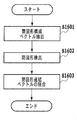
文字コード情報統合処理が開始されると(S2900)、ステップS2901において、OCR処理部704の処理によって得られた文字コード情報と文字コード情報抽出処理部2701で抽出された文字コード情報2の対応関係の照合を行う。
When the character code information integration processing is started (S2900), in step S2901, the correspondence between the character code information obtained by the processing of the
次に、ステップS2902において、位置・サイズが概略同じ文字コード情報を抽出する。 Next, in step S2902, character code information having approximately the same position and size is extracted.
次いで、ステップS2903でそれぞれの文字コード情報に含まれる文字コード列の形態素解析を行う。 Next, in step S2903, morphological analysis of the character code string included in each character code information is performed.
そして、ステップS2904の形態素解析で得られた結果に不明語が少ないほうの文字コード情報を採用してこれを出力し、全体の処理を終える(S2904)。 Then, the character code information with fewer unknown words is adopted in the result obtained by the morphological analysis in step S2904, and this is output, and the entire process is finished (S2904).
以上の処理により、得られる文字コード情報の信頼性を向上することが可能となる。 Through the above processing, it is possible to improve the reliability of the obtained character code information.
どちらの文字コードを出力するかを決定するルールとしては、以下のようなものを考えることもできる。すなわち、テキストオブジェクトが一文字一文字ばらばらに分解されPDLデータとして送られてくる場合には、文字コード情報2は一文字のものばかりを含んでしまい、形態素解析の結果はほとんど意味のないものとなる。従って、文字コード列が長い方を採用するというルール付けをおこなってもよい。
The following can be considered as a rule for determining which character code to output. That is, when a text object is decomposed into individual characters and sent as PDL data, the
<第四の実施形態>
前述の第三の実施形態でMFP100側に導入したテキストオブジェクト変換処理部2201による処理は、プリンタドライバ側で行ってもよい。
<Fourth embodiment>
The processing by the text object
図30は、クライアントPC102側の構成としてテキストオブジェクト変換処理2部3001を追加した例を示している。テキストオブジェクト変換処理2部3001の処理内容は、テキストオブジェクト変換処理部2201と同様の処理を行う。
FIG. 30 shows an example in which a text object conversion processing
ドライバUI600でPDLデータのBOX保存の指定がなされた際には、プリンタドライバ302からのPDLデータ送信は、テキストオブジェクト変換を行わない通常のPDLデータの送信となる。次に、OCR専用のレンダリングを行う指定とともに、テキストオブジェクト変換処理がなされたPDLデータを送信する。
When the
MFP100側では、プリンタドライバ302からの一回目のPDLデータ受信の際には、通常のBitmapスプール201に画像データが展開されるように制御する。そして、2回目のPDLデータ受信の際には、OCR専用Bitmapスプール2202にPDLデータが展開されるように制御する。
On the
通常のBitmapスプール201とOCR専用Bitmapスプール2202へ画像データの展開がなされた後の処理については、前述の第二あるいは第三の実施形態で説明した処理と同様に処理を行えばよい。
The processing after the image data is developed on the
また、本実施形態においては、PDL処理部304に接続されるテキストオブジェクト変換処理部2201は必ずしも必要ではなくなる。
In the present embodiment, the text object
本実施形態の構成によれば、クライアントPC102側でアプリケーションとプリンタドライバの処理によって、もともとテキストデータであったものが、イメージデータになったりPathデータになったりするケースを低減させることができる。このため、「見た目はテキストデータであるにも係わらず、内部で保持しているデータとしては、Pathデータやイメージデータである場合に文字コードが得られない」という問題の解決にさらに寄与できる。 According to the configuration of the present embodiment, it is possible to reduce the case where the text data originally becomes image data or Path data by the processing of the application and printer driver on the client PC 102 side. For this reason, it is possible to further contribute to the solution of the problem that “the character code cannot be obtained when the data is internally stored as Path data or image data even though it looks as text data”.
<その他の実施の形態>
前述の第一から第四の実施形態においては、PDLデータがBOXに保存される際には、PDLデータがレンダリングされた画像データをオブジェクト分割して、ベクトル化処理、JPEG圧縮処理、OCR処理がされるものとして説明してきた。しかし、図31に示すように、PDL処理部304で生成されたDisplayList情報をそのまま画像格納処理部200に渡すようにしてもよい。
<Other embodiments>
In the first to fourth embodiments described above, when the PDL data is stored in the BOX, the image data on which the PDL data is rendered is divided into objects, and vectorization processing, JPEG compression processing, and OCR processing are performed. Has been described as being. However, as shown in FIG. 31, the display list information generated by the
このとき、MFP100は、テキストオブジェクト変換処理されていないPDLデータから生成されたDisplayListをそのまま画像格納処理部200に渡すように制御する。そして、テキストオブジェクト変換処理を施したPDLデータはレンダラ305でOCR専用Bitmapデータとしてレンダリングされるように制御する。
At this time, the
図32に示すように、画像格納処理部200は、入力されたDisplayListが、3201においてSVGデータに直接変換されるように制御する。もともと、DisplayList上では、Imageオブジェクト、Graphicsオブジェクト、Textオブジェクトはオブジェクト分割されており、Graphicsオブジェクトはベクトル表現であるため、ある程度の直接変換が可能である。
As shown in FIG. 32, the image
一方、これとは別に、OCR専用Bitmapデータから、オブジェクト分割処理2部706によって得られた文字画像領域に対してOCR処理部704による処理を施す。そして文字コード情報を抽出し、第一から第四の実施形態で説明してきたようにメタデータ付与処理を行う。
On the other hand, the
以上、説明してきたように、本実施形態においても、PDLデータ中の文字オブジェクトから文字コードを取り出して、それを検索のためのインデックスとする際の問題点を効果的に解決し、信頼性のある文書格納を行う画像処理装置を提供することが可能である。 As described above, also in this embodiment, the problem in extracting the character code from the character object in the PDL data and using it as the index for search is effectively solved, and the reliability is improved. It is possible to provide an image processing apparatus that stores a certain document.
以上、本発明の諸実施形態について説明した。 The embodiments of the present invention have been described above.
なお、本発明の目的は、上述した実施形態で示したフローチャートの手順を実現するプログラムコードを記憶した記憶媒体から、システムあるいは装置のコンピュータ(またはCPUやMPU)がそのプログラムコードを読出し実行することによっても達成される。
この場合、記憶媒体から読み出されたプログラムコード自体が、コンピュータに、上述した実施形態の機能を実現させることになる。そのため、このプログラムコード及びプログラムコードを記憶/記録したコンピュータ読み取り可能な記憶媒体も本発明の一つを構成することになる。
An object of the present invention is that a computer (or CPU or MPU) of a system or apparatus reads and executes the program code from a storage medium that stores the program code for realizing the procedure of the flowchart shown in the above-described embodiment. Is also achieved.
In this case, the program code itself read from the storage medium causes the computer to realize the functions of the above-described embodiments. Therefore, the program code and a computer-readable storage medium storing / recording the program code also constitute one aspect of the present invention.
プログラムコードを供給するための記憶媒体としては、例えば、フロッピー(登録商標)ディスク、ハードディスク、光ディスク、光磁気ディスク、CD−ROM、CD−R、磁気テープ、不揮発性のメモリカード、ROMなどを用いることができる。 As a storage medium for supplying the program code, for example, a floppy (registered trademark) disk, hard disk, optical disk, magneto-optical disk, CD-ROM, CD-R, magnetic tape, nonvolatile memory card, ROM, or the like is used. be able to.
また、前述した実施形態の機能は、コンピュータが、読み出したプログラムを実行することによって実現される。また、このプログラムの実行とは、そのプログラムの指示に基づき、コンピュータ上で稼動しているOSなどが、実際の処理の一部または全部を行う場合も含まれる。 The functions of the above-described embodiments are realized by a computer executing a read program. The execution of the program includes a case where an OS or the like running on the computer performs part or all of the actual processing based on an instruction of the program.
さらに、前述した実施形態の機能は、コンピュータに挿入された機能拡張ボードやコンピュータに接続された機能拡張ユニットによっても実現することもできる。この場合、まず、記憶媒体から読み出されたプログラムが、コンピュータに挿入された機能拡張ボードやコンピュータに接続された機能拡張ユニットに備わるメモリに書き込まれる。その後、そのプログラムの指示に基づき、その機能拡張ボードや機能拡張ユニットに備わるCPUなどが実際の処理の一部または全部を行う。こうした機能拡張ボードや機能拡張ユニットによる処理によっても前述した実施形態の機能が実現される。 Furthermore, the functions of the above-described embodiments can also be realized by a function expansion board inserted into a computer or a function expansion unit connected to a computer. In this case, first, the program read from the storage medium is written in a memory provided in a function expansion board inserted into the computer or a function expansion unit connected to the computer. Thereafter, based on the instructions of the program, the CPU provided in the function expansion board or function expansion unit performs part or all of the actual processing. The functions of the above-described embodiment are also realized by processing by such a function expansion board or function expansion unit.
100 MFP
101 LAN
102 クライアントPC
103 文書管理サーバ
104 データベース
110 画像読み取り装置
111 読み取り画像処理部
112 出力画像処理部
113 画像記録装置
114 ネットワークI/F
115 記憶部
116 入力装置
117 表示装置
118 CPU
119 RAM
120 ROM
200 画像格納処理部
201 Bitmapスプール
202 画像送信処理部
301 アプリ(アプリケーション)
302 プリンタドライバ
303 PDLデータスプール
304 PDL処理部
305 レンダラ
701 オブジェクト分割処理部
702 JPEG圧縮処理部
703 ベクトル化処理部
704 OCR処理部
705 メタデータ付与部
706 オブジェクト分割処理2部
707 文字コード統合処理部
2201 テキストオブジェクト変換処理部
2202 OCR専用Bitmapスプール
2701 文字コード情報抽出処理部
3000 テキストオブジェクト変換処理2部
3201 DisplayList→ベクトル化データ変換部
100 MFP
101 LAN
102 Client PC
DESCRIPTION OF
119 RAM
120 ROM
200 Image
302
Claims (10)
前記レンダリング手段で得た画像データの中から文字オブジェクトを抽出する抽出手段と、
前記抽出手段により抽出された文字オブジェクトに対して文字認識処理を実行することにより文字コード情報を得る文字認識手段と、
前記PDLデータに含まれる第2の文字コード情報を抽出する文字コード抽出手段と、
前記文字認識手段により得られた前記文字コード情報と前記文字コード抽出手段によって抽出された前記第2の文字コード情報とを比較し、当該比較結果に従って、より信頼性の高い文字コード情報を採用する統合手段と、
前記統合手段によって採用された前記より信頼性の高い文字コード情報を含むメタデータを前記画像データに付与するメタデータ付与手段と
を備えることを特徴とする画像処理装置。 Rendering means for obtaining image data by rendering PDL data;
Extraction means for extracting a character object from the image data obtained by the rendering means;
Character recognition means for obtaining character code information by executing character recognition processing on the character object extracted by the extraction means;
Character code extracting means for extracting second character code information included in the PDL data;
The character code information obtained by the character recognition means is compared with the second character code information extracted by the character code extraction means, and more reliable character code information is adopted according to the comparison result. Integration means,
An image processing apparatus comprising: metadata adding means for adding metadata including the more reliable character code information adopted by the integrating means to the image data.
前記文字認識手段は、前記第2のレンダリングバッファに保存された画像データに対して文字認識処理を実行することにより文字コード情報を得て、
前記メタデータ付与手段は、前記メタデータを前記第1のレンダリングバッファに保存された画像データに付与する
ことを特徴とする請求項1に記載の画像処理装置。 The rendering means stores image data rendered by normal rendering processing on the PDL data in a first rendering buffer, converts the character object included in the PDL data, and renders the rendered image data in a second rendering buffer. Save to
The character recognition means obtains character code information by executing character recognition processing on the image data stored in the second rendering buffer,
The meta data providing means, the image processing apparatus according to pre-decided metadata to claim 1, characterized in that applied to the image data stored in said first rendering buffer.
前記メタデータ付与手段は、前記メタデータを、前記ベクトル化手段で変換された前記画像データ内のオブジェクトのベクトルデータに付与する
ことを特徴とする請求項1に記載の画像処理装置。 Further comprising vectorization means for converting an object in the image data into vector data;
The meta data providing means, before the texture metadata, image processing apparatus according to claim 1, characterized in that applied to the vector data of the objects in the converted the image data in the vectorization means.
前記プリンタドライバは、前記アプリケーションから受け取った描画情報をPDLデータに変換する際に、当該PDLデータに含まれる文字オブジェクトの座標、サイズ、フォント情報、修飾情報のうちの少なくともいずれかを変更する変換手段を備える
ことを特徴とする画像処理システム。 2. An image processing apparatus according to claim 1, and a host computer including a printer driver having a function of receiving drawing information from an application and transmitting PDL data converted based on the drawing information to the image processing apparatus. An image processing system connected via
The printer driver converts at least one of coordinates, size, font information, and modification information of a character object included in the PDL data when converting the drawing information received from the application into PDL data. An image processing system comprising:
前記レンダリングステップで得た画像データの中から文字オブジェクトを抽出する抽出ステップと、
前記抽出ステップで抽出された文字オブジェクトに対して文字認識処理を実行することにより文字コード情報を得る文字認識ステップと、
前記PDLデータに含まれる第2の文字コード情報を抽出する文字コード抽出ステップと、
前記文字認識ステップにより得られた前記文字コード情報と前記文字コード抽出ステップによって抽出された前記第2の文字コード情報とを比較し、当該比較結果に従って、より信頼性の高い文字コード情報を採用する統合ステップと、
前記統合ステップによって採用された前記より信頼性の高い文字コード情報を含むメタデータを前記画像データに付与するメタデータ付与ステップと
を含むことを特徴とする画像処理方法。 A rendering step of obtaining image data by rendering PDL data;
An extraction step of extracting a character object from the image data obtained in the rendering step;
A character recognition step of obtaining character code information by executing a character recognition process on the character object extracted in the extraction step;
A character code extracting step of extracting second character code information included in the PDL data;
The character code information obtained in the character recognition step is compared with the second character code information extracted in the character code extraction step, and more reliable character code information is adopted according to the comparison result. Integration steps,
An image processing method comprising: a metadata adding step for adding metadata including the more reliable character code information adopted in the integration step to the image data.
Priority Applications (2)
| Application Number | Priority Date | Filing Date | Title |
|---|---|---|---|
| JP2008179204A JP5111268B2 (en) | 2008-07-09 | 2008-07-09 | Image processing apparatus, image processing method, program thereof, and storage medium |
| US12/496,601 US8320019B2 (en) | 2008-07-09 | 2009-07-01 | Image processing apparatus, image processing method, and computer program thereof |
Applications Claiming Priority (1)
| Application Number | Priority Date | Filing Date | Title |
|---|---|---|---|
| JP2008179204A JP5111268B2 (en) | 2008-07-09 | 2008-07-09 | Image processing apparatus, image processing method, program thereof, and storage medium |
Publications (3)
| Publication Number | Publication Date |
|---|---|
| JP2010020468A JP2010020468A (en) | 2010-01-28 |
| JP2010020468A5 JP2010020468A5 (en) | 2011-08-18 |
| JP5111268B2 true JP5111268B2 (en) | 2013-01-09 |
Family
ID=41705305
Family Applications (1)
| Application Number | Title | Priority Date | Filing Date |
|---|---|---|---|
| JP2008179204A Expired - Fee Related JP5111268B2 (en) | 2008-07-09 | 2008-07-09 | Image processing apparatus, image processing method, program thereof, and storage medium |
Country Status (2)
| Country | Link |
|---|---|
| US (1) | US8320019B2 (en) |
| JP (1) | JP5111268B2 (en) |
Families Citing this family (30)
| Publication number | Priority date | Publication date | Assignee | Title |
|---|---|---|---|---|
| US9495386B2 (en) | 2008-03-05 | 2016-11-15 | Ebay Inc. | Identification of items depicted in images |
| WO2009111047A2 (en) | 2008-03-05 | 2009-09-11 | Ebay Inc. | Method and apparatus for image recognition services |
| US8818978B2 (en) | 2008-08-15 | 2014-08-26 | Ebay Inc. | Sharing item images using a similarity score |
| US8825660B2 (en) * | 2009-03-17 | 2014-09-02 | Ebay Inc. | Image-based indexing in a network-based marketplace |
| US9164577B2 (en) | 2009-12-22 | 2015-10-20 | Ebay Inc. | Augmented reality system, method, and apparatus for displaying an item image in a contextual environment |
| JP5249387B2 (en) | 2010-07-06 | 2013-07-31 | キヤノン株式会社 | Image processing apparatus, image processing method, and program |
| JP5676942B2 (en) | 2010-07-06 | 2015-02-25 | キヤノン株式会社 | Image processing apparatus, image processing method, and program |
| US10127606B2 (en) | 2010-10-13 | 2018-11-13 | Ebay Inc. | Augmented reality system and method for visualizing an item |
| JP5323035B2 (en) | 2010-12-10 | 2013-10-23 | キヤノン株式会社 | Image forming apparatus and image forming method |
| JP5055418B2 (en) | 2010-12-10 | 2012-10-24 | キヤノン株式会社 | Image processing apparatus and image processing method |
| US20120159292A1 (en) * | 2010-12-16 | 2012-06-21 | Oce-Technologies B.V. | Method of processing an object-based image file with content type dependent image processing algorithms |
| US8977044B2 (en) * | 2011-02-18 | 2015-03-10 | Fuji Xerox Co., Ltd. | Image processing apparatus for area separation of images, image processing method, and computer readable medium |
| JP5285727B2 (en) * | 2011-02-22 | 2013-09-11 | シャープ株式会社 | Image forming apparatus and image forming method |
| US9449342B2 (en) | 2011-10-27 | 2016-09-20 | Ebay Inc. | System and method for visualization of items in an environment using augmented reality |
| JP5984439B2 (en) * | 2012-03-12 | 2016-09-06 | キヤノン株式会社 | Image display device and image display method |
| US9934522B2 (en) | 2012-03-22 | 2018-04-03 | Ebay Inc. | Systems and methods for batch- listing items stored offline on a mobile device |
| US10846766B2 (en) | 2012-06-29 | 2020-11-24 | Ebay Inc. | Contextual menus based on image recognition |
| JP5954691B2 (en) | 2012-09-28 | 2016-07-20 | ブラザー工業株式会社 | Template processing program and template processing method |
| US9208381B1 (en) * | 2012-12-13 | 2015-12-08 | Amazon Technologies, Inc. | Processing digital images including character recognition using ontological rules |
| CN104423900B (en) * | 2013-08-27 | 2018-04-27 | 北大方正集团有限公司 | Image printing method and printer |
| JP6000992B2 (en) * | 2014-01-24 | 2016-10-05 | 京セラドキュメントソリューションズ株式会社 | Document file generation apparatus and document file generation method |
| US20170161595A1 (en) * | 2015-12-07 | 2017-06-08 | Xerox Corporation | Direct character recognition from page description language document |
| TWI608713B (en) * | 2015-12-31 | 2017-12-11 | 宏正自動科技股份有限公司 | Active security protection system |
| JP6808330B2 (en) * | 2016-02-26 | 2021-01-06 | キヤノン株式会社 | Information processing equipment, information processing methods, and programs |
| JP6769045B2 (en) * | 2016-02-29 | 2020-10-14 | ブラザー工業株式会社 | Image processing equipment and computer programs |
| JP7013182B2 (en) | 2017-09-21 | 2022-01-31 | キヤノン株式会社 | Information processing equipment, information processing methods and programs |
| US11087469B2 (en) * | 2018-07-12 | 2021-08-10 | Here Global B.V. | Method, apparatus, and system for constructing a polyline from line segments |
| JP7224856B2 (en) * | 2018-11-02 | 2023-02-20 | キヤノン株式会社 | Image generation device, image generation method, and program |
| JP2022100071A (en) | 2020-12-23 | 2022-07-05 | キヤノン株式会社 | Image processing apparatus, image processing system, control method for the same, and program |
| JP2022159774A (en) | 2021-04-05 | 2022-10-18 | キヤノン株式会社 | Image processing apparatus, image processing system, control method for the same, and program |
Family Cites Families (9)
| Publication number | Priority date | Publication date | Assignee | Title |
|---|---|---|---|---|
| JP3683925B2 (en) | 1994-11-18 | 2005-08-17 | キヤノン株式会社 | Electronic filing device |
| US5907835A (en) * | 1994-11-18 | 1999-05-25 | Canon Kabushiki Kaisha | Electronic filing system using different application program for processing drawing commands for printing |
| JPH10228473A (en) * | 1997-02-13 | 1998-08-25 | Ricoh Co Ltd | Document image processing method, document image processing device, and storage medium |
| JP2002077609A (en) * | 2000-09-05 | 2002-03-15 | Canon Inc | Image determining apparatus, copying machine, and image determining method |
| JP4087191B2 (en) * | 2002-08-16 | 2008-05-21 | 株式会社リコー | Image processing apparatus, image processing method, and image processing program |
| JP2004272658A (en) * | 2003-03-10 | 2004-09-30 | Geomic Co Ltd | Text data input support method and device for personal digital assistance |
| JP4266784B2 (en) * | 2003-11-14 | 2009-05-20 | キヤノン株式会社 | Image processing system and image processing method |
| US20060085442A1 (en) * | 2004-10-20 | 2006-04-20 | Kabushiki Kaisha Toshiba | Document image information management apparatus and document image information management program |
| JP4928373B2 (en) * | 2007-07-12 | 2012-05-09 | キヤノン株式会社 | Image processing apparatus, image processing method, and image processing program |
-
2008
- 2008-07-09 JP JP2008179204A patent/JP5111268B2/en not_active Expired - Fee Related
-
2009
- 2009-07-01 US US12/496,601 patent/US8320019B2/en not_active Expired - Fee Related
Also Published As
| Publication number | Publication date |
|---|---|
| JP2010020468A (en) | 2010-01-28 |
| US8320019B2 (en) | 2012-11-27 |
| US20100171999A1 (en) | 2010-07-08 |
Similar Documents
| Publication | Publication Date | Title |
|---|---|---|
| JP5111268B2 (en) | Image processing apparatus, image processing method, program thereof, and storage medium | |
| JP4251629B2 (en) | Image processing system, information processing apparatus, control method, computer program, and computer-readable storage medium | |
| JP4502385B2 (en) | Image processing apparatus and control method thereof | |
| JP5376795B2 (en) | Image processing apparatus, image processing method, program thereof, and storage medium | |
| JP4960817B2 (en) | Image processing apparatus and image processing method | |
| JP7262993B2 (en) | Image processing system, image processing method, image processing apparatus | |
| US8384936B2 (en) | System which performs resolution-dependent vectorization of print data | |
| US20120250048A1 (en) | Image processing apparatus and image processing method | |
| JP2009193356A (en) | Image processing apparatus, image processing method, program, and storage medium | |
| US20060029293A1 (en) | Image processing system, image forming apparatus, control method for the same, and program for implementing the control method | |
| JP2006285612A (en) | Information processing apparatus and method | |
| JP2005159517A (en) | Image processing apparatus, control method therefor, and program | |
| JP2010074540A (en) | Image processing apparatus | |
| JP4533273B2 (en) | Image processing apparatus, image processing method, and program | |
| JP2006243942A (en) | Image processing apparatus and method | |
| JP4533187B2 (en) | Image processing apparatus and control method thereof | |
| JP2008109394A (en) | Image processing apparatus and method, and program | |
| US8181108B2 (en) | Device for editing metadata of divided object | |
| JP2006023944A (en) | Image processing system and image processing method | |
| JP4785655B2 (en) | Document processing apparatus and document processing method | |
| JP2009211554A (en) | Image processor, image processing method, computer program, and storage medium | |
| JP5132347B2 (en) | Image processing system | |
| JP5100354B2 (en) | Image processing apparatus, image processing method, and computer program | |
| JP7301529B2 (en) | Image processing device, image processing method, and program | |
| JP2010073165A (en) | Information processor, control method for the same, and computer program |
Legal Events
| Date | Code | Title | Description |
|---|---|---|---|
| RD02 | Notification of acceptance of power of attorney |
Free format text: JAPANESE INTERMEDIATE CODE: A7422 Effective date: 20101106 |
|
| A521 | Written amendment |
Free format text: JAPANESE INTERMEDIATE CODE: A523 Effective date: 20110705 |
|
| A621 | Written request for application examination |
Free format text: JAPANESE INTERMEDIATE CODE: A621 Effective date: 20110705 |
|
| A977 | Report on retrieval |
Free format text: JAPANESE INTERMEDIATE CODE: A971007 Effective date: 20120621 |
|
| A131 | Notification of reasons for refusal |
Free format text: JAPANESE INTERMEDIATE CODE: A131 Effective date: 20120626 |
|
| A521 | Written amendment |
Free format text: JAPANESE INTERMEDIATE CODE: A523 Effective date: 20120827 |
|
| TRDD | Decision of grant or rejection written | ||
| A01 | Written decision to grant a patent or to grant a registration (utility model) |
Free format text: JAPANESE INTERMEDIATE CODE: A01 Effective date: 20120911 |
|
| A01 | Written decision to grant a patent or to grant a registration (utility model) |
Free format text: JAPANESE INTERMEDIATE CODE: A01 |
|
| A61 | First payment of annual fees (during grant procedure) |
Free format text: JAPANESE INTERMEDIATE CODE: A61 Effective date: 20121009 |
|
| FPAY | Renewal fee payment (event date is renewal date of database) |
Free format text: PAYMENT UNTIL: 20151019 Year of fee payment: 3 |
|
| R151 | Written notification of patent or utility model registration |
Ref document number: 5111268 Country of ref document: JP Free format text: JAPANESE INTERMEDIATE CODE: R151 |
|
| FPAY | Renewal fee payment (event date is renewal date of database) |
Free format text: PAYMENT UNTIL: 20151019 Year of fee payment: 3 |
|
| LAPS | Cancellation because of no payment of annual fees |