JP5110161B2 - Image correction apparatus, image correction program, and image correction method - Google Patents
Image correction apparatus, image correction program, and image correction method Download PDFInfo
- Publication number
- JP5110161B2 JP5110161B2 JP2010516700A JP2010516700A JP5110161B2 JP 5110161 B2 JP5110161 B2 JP 5110161B2 JP 2010516700 A JP2010516700 A JP 2010516700A JP 2010516700 A JP2010516700 A JP 2010516700A JP 5110161 B2 JP5110161 B2 JP 5110161B2
- Authority
- JP
- Japan
- Prior art keywords
- image
- dark
- processing target
- target image
- distribution bias
- Prior art date
- Legal status (The legal status is an assumption and is not a legal conclusion. Google has not performed a legal analysis and makes no representation as to the accuracy of the status listed.)
- Expired - Fee Related
Links
Images


Classifications
-
- H—ELECTRICITY
- H04—ELECTRIC COMMUNICATION TECHNIQUE
- H04N—PICTORIAL COMMUNICATION, e.g. TELEVISION
- H04N5/00—Details of television systems
- H04N5/14—Picture signal circuitry for video frequency region
- H04N5/16—Circuitry for reinsertion of dc and slowly varying components of signal; Circuitry for preservation of black or white level
-
- H—ELECTRICITY
- H04—ELECTRIC COMMUNICATION TECHNIQUE
- H04N—PICTORIAL COMMUNICATION, e.g. TELEVISION
- H04N21/00—Selective content distribution, e.g. interactive television or video on demand [VOD]
- H04N21/40—Client devices specifically adapted for the reception of or interaction with content, e.g. set-top-box [STB]; Operations thereof
- H04N21/43—Processing of content or additional data, e.g. demultiplexing additional data from a digital video stream; Elementary client operations, e.g. monitoring of home network or synchronising decoder's clock; Client middleware
- H04N21/431—Generation of visual interfaces for content selection or interaction; Content or additional data rendering
- H04N21/4318—Generation of visual interfaces for content selection or interaction; Content or additional data rendering by altering the content in the rendering process, e.g. blanking, blurring or masking an image region
-
- H—ELECTRICITY
- H04—ELECTRIC COMMUNICATION TECHNIQUE
- H04N—PICTORIAL COMMUNICATION, e.g. TELEVISION
- H04N21/00—Selective content distribution, e.g. interactive television or video on demand [VOD]
- H04N21/40—Client devices specifically adapted for the reception of or interaction with content, e.g. set-top-box [STB]; Operations thereof
- H04N21/43—Processing of content or additional data, e.g. demultiplexing additional data from a digital video stream; Elementary client operations, e.g. monitoring of home network or synchronising decoder's clock; Client middleware
- H04N21/44—Processing of video elementary streams, e.g. splicing a video clip retrieved from local storage with an incoming video stream, rendering scenes according to MPEG-4 scene graphs
- H04N21/44008—Processing of video elementary streams, e.g. splicing a video clip retrieved from local storage with an incoming video stream, rendering scenes according to MPEG-4 scene graphs involving operations for analysing video streams, e.g. detecting features or characteristics in the video stream
-
- H—ELECTRICITY
- H04—ELECTRIC COMMUNICATION TECHNIQUE
- H04N—PICTORIAL COMMUNICATION, e.g. TELEVISION
- H04N5/00—Details of television systems
- H04N5/14—Picture signal circuitry for video frequency region
- H04N5/20—Circuitry for controlling amplitude response
-
- H—ELECTRICITY
- H04—ELECTRIC COMMUNICATION TECHNIQUE
- H04N—PICTORIAL COMMUNICATION, e.g. TELEVISION
- H04N5/00—Details of television systems
- H04N5/44—Receiver circuitry for the reception of television signals according to analogue transmission standards
- H04N5/57—Control of contrast or brightness
Description
本発明は、画像補正装置、画像補正プログラムおよび画像補正方法に関する。 The present invention relates to an image correction apparatus, an image correction program, and an image correction method.
一般的に、デジタルテレビにおける暗いシーン(暗部)の再現は、黒色をいかに出力するかによって画像の締まり具合が左右される。このため、従来より、デジタル画像の補正においては、暗部が明るくなることにより生じる黒浮き、および、暗部が暗くなることにより生じる黒潰れを抑制することが要求されている。 In general, the reproduction of dark scenes (dark parts) on a digital television depends on how tightly the image is output depending on how black is output. For this reason, conventionally, in the correction of a digital image, it is required to suppress black floating that occurs when a dark part becomes bright and black crushing that occurs when a dark part becomes dark.
そして、最近では、暗い画像を補正する様々な技術が開示されている。例えば、暗い画像を補正する技術としては、画像の平均明度により、当該画像が暗ければ暗いほど、より明るく補正するものがある。また、例えば、一般的なダイナミックレンジ補正技術としては、画素数が画像全体の0.1%〜1.0%程度である画像の最も暗い部分の画素をレベル「0」になるような線形補間によって補正するものがある。 Recently, various techniques for correcting dark images have been disclosed. For example, as a technique for correcting a dark image, there is a technique for correcting brighter the darker the image, based on the average brightness of the image. Further, for example, as a general dynamic range correction technique, linear interpolation is performed such that the darkest pixel of an image whose number of pixels is about 0.1% to 1.0% of the entire image is level “0”. There is something to correct by.
また、例えば、特許文献1では、画像全体のヒストグラムを生成し、図13に示すように、当該画像の暗部である黒領域において、基準値A以下の画素の分布数と基準値B以上の画素の分布数とに基づいて補正量を算出している。なお、図13は、従来技術に係る暗い画像を補正する技術について説明するための図である。
Also, for example, in
しかしながら、上記した従来の技術は、黒浮きまたは黒潰れを抑制することができないという課題があった。 However, the above-described conventional technique has a problem that black floating or black crushing cannot be suppressed.
具体的には、画像全体の平均明度によって画像を補正する技術は、暗い画像であると判定された画像に対して、常に一定量で明るく補正するため、画像によっては黒浮きが発生する可能性がある。また、一般的なダイナミックレンジ補正技術は、通常の明度である画像を補正する場合に効果があるが、非常に暗い画像を補正する場合に、当該暗い画像は既に1.0%以上のレベル「0」を含むため、画像が補正されることはない。 Specifically, the technique that corrects an image based on the average brightness of the entire image always corrects the image determined to be a dark image brightly by a constant amount, and depending on the image, there is a possibility that black floating may occur. There is. In addition, a general dynamic range correction technique is effective when correcting an image having normal brightness. However, when correcting a very dark image, the dark image is already at a level “1.0% or higher”. 0 "is included, so the image is not corrected.
また、特許文献1は、図14−1に示すように、黒領域において特に明るい領域に画素が集中している場合に(黒領域において明度が高い画素数が多い場合に)、黒浮きが生じる可能性がある。さらに、特許文献1は、図14−2に示すように、黒領域において特に暗い領域に画素が集中している場合に(黒領域において明度が低い画素数が多い場合に)、黒潰れが生じる可能性がある。
In
つまり、特許文献1は、図14−1または図14−2に示すような画像に対して、同様に補正量を算出するために、少なくとも一方の画像において黒浮きまたは黒潰れが生じる可能性がある。この結果、上記した従来の技術は、黒浮きまたは黒潰れを抑制することができない。なお、図14−1は、明るい領域に画素が集中している画像の暗部を示す図であり、図14−2は、暗い領域に画素が集中している画像の暗部を示す図である。
That is, since
そこで、本発明は、上記した従来技術の課題を解決するためになされたものであり、暗い画像を補正する場合に、黒浮きまたは黒潰れを抑制することが可能である画像補正装置、画像補正プログラムおよび画像補正方法を提供することを目的とする。 Accordingly, the present invention has been made to solve the above-described problems of the prior art, and in correcting a dark image, an image correction apparatus and an image correction capable of suppressing black floating or black crushing It is an object to provide a program and an image correction method.
上述した課題を解決し、目的を達成するため、本願の開示する画像補正装置は、処理対象画像の各画素の画素値に基づいて、前記処理対象画像が暗い画像であるか否かを判定する画像判定手段と、前記画像判定手段によって前記処理対象画像が暗い画像であると判定された場合に、当該暗い画像である処理対象画像において、第一の値よりも低い部分を示す暗部の画素の出現頻度の分布偏りを算出する暗部分布偏り算出手段と、前記暗部分布偏り算出手段によって算出された分布偏りに基づいて、前記処理対象画像に対する補正量を決定する補正量決定手段と、を備えたことを要件とする。 In order to solve the above-described problems and achieve the object, the image correction apparatus disclosed in the present application determines whether or not the processing target image is a dark image based on the pixel value of each pixel of the processing target image. In the case where the image to be processed is determined to be a dark image by the image determination unit and the image determination unit, in the processing target image that is the dark image, the pixel of the dark portion that indicates a portion lower than the first value A dark part distribution bias calculating unit that calculates a distribution bias of the appearance frequency; and a correction amount determining unit that determines a correction amount for the processing target image based on the distribution bias calculated by the dark part distribution bias calculating unit. Is a requirement.
本願の開示する画像補正装置によれば、暗い画像を補正する場合に、黒浮きまたは黒潰れを抑制することが可能であるという効果を奏する。 According to the image correction apparatus disclosed in the present application, when a dark image is corrected, there is an effect that it is possible to suppress black floating or black crushing.
10 画像補正装置
20 記憶部
30 制御部
31 画像判定部
32 暗部分布偏り算出部
33 補正量決定部
34 画像補正部DESCRIPTION OF
以下に、添付図面を参照して、本発明に係る画像補正装置の実施例を詳細に説明する。 Embodiments of an image correction apparatus according to the present invention will be described below in detail with reference to the accompanying drawings.
[画像補正装置の概要]
最初に、実施例1に係る画像補正装置の概要を説明する。本願の開示する画像補正装置は、デジタルテレビなどの内部に配設され、入力される処理対象画像を補正して出力する装置である。なお、画像補正装置は、デジタルテレビだけでなく、ワンセグ(1セグメント放送)端末、PC(Personal Computer)、画像データ中継装置などにも適用可能である。[Outline of image correction device]
First, the outline of the image correction apparatus according to the first embodiment will be described. An image correction apparatus disclosed in the present application is an apparatus that is disposed inside a digital television or the like and corrects and outputs an input processing target image. Note that the image correction apparatus can be applied not only to a digital television but also to a one-segment (one-segment broadcasting) terminal, a PC (Personal Computer), an image data relay apparatus, and the like.
上記した構成において、画像補正装置は、処理対象画像の各画素の画素値に基づいて、当該処理対象画像が暗い画像であるか否かを判定する。そして、画像補正装置は、処理対象画像が暗い画像であると判定された場合に、当該暗い画像である処理対象画像において、第一の値よりも低い部分を示す暗部の画素の出現頻度の分布偏りを算出する。続いて、画像補正装置は、算出された分布偏りに基づいて、処理対象画像に対する補正量を決定する。その後、画像補正装置は、決定された補正量で画像を補正する。 In the configuration described above, the image correction apparatus determines whether or not the processing target image is a dark image based on the pixel value of each pixel of the processing target image. Then, when it is determined that the processing target image is a dark image, the image correction apparatus distributes the appearance frequency of the pixels in the dark portion indicating the lower portion than the first value in the processing target image that is the dark image. Calculate the bias. Subsequently, the image correction apparatus determines a correction amount for the processing target image based on the calculated distribution bias. Thereafter, the image correction apparatus corrects the image with the determined correction amount.
具体的には、画像補正装置は、入力された処理対象画像が暗い画像である場合に、暗部の画素の出現頻度の分布偏りを算出する。そして、画像補正装置は、算出された暗部の分布偏りが非常に暗い部分に偏っている場合に、黒潰れの可能性があると判定し、算出された暗部の分布偏りがやや暗い部分に偏っている場合に、黒浮きの可能性があると判定する。続いて、画像補正装置は、黒浮きまたは黒潰れの可能性があると判定された処理対象画像に応じた補正量(補正カーブ)を決定して補正する。 Specifically, the image correction apparatus calculates the distribution bias of the appearance frequency of the pixels in the dark part when the input processing target image is a dark image. Then, the image correction device determines that there is a possibility of black crushing when the calculated dark portion distribution bias is biased toward a very dark portion, and the calculated dark portion distribution bias is biased toward a slightly dark portion. If it is, it is determined that there is a possibility of black float. Subsequently, the image correction apparatus determines and corrects a correction amount (correction curve) corresponding to the processing target image that is determined to have the possibility of black floating or black collapse.
上記したように、画像補正装置は、処理対象画像における暗部の画素の出現頻度の分布偏りに応じて、処理対象画像に対する補正量を決定することができる結果、従来技術のように、画像の暗い部分の画素数に応じて補正量を決定し、当該画像の暗い部分全体を一定量で補正するのと比較して、黒浮きまたは黒潰れを抑制することが可能である。 As described above, the image correction apparatus can determine the correction amount for the processing target image according to the distribution bias of the appearance frequency of the pixels in the dark part in the processing target image. Compared with determining the correction amount according to the number of pixels in the portion and correcting the entire dark portion of the image with a fixed amount, it is possible to suppress black floating or blackout.
[画像補正装置の構成]
次に、図1を用いて、実施例1に係る画像補正装置の構成を説明する。図1は、実施例1に係る画像補正装置の構成を示す図である。図1に示すように、画像補正装置10は、記憶部20と、制御部30とを有し、入力される処理対象画像を補正して出力する。[Configuration of image correction apparatus]
Next, the configuration of the image correction apparatus according to the first embodiment will be described with reference to FIG. FIG. 1 is a diagram illustrating the configuration of the image correction apparatus according to the first embodiment. As shown in FIG. 1, the
記憶部20は、制御部30による各種処理に必要なデータや、制御部30による各種処理結果を記憶する。例えば、記憶部20は、制御部30による画像補正処理に必要な補正カーブや、制御部30による画像補正処理結果を記憶する。
The
制御部30は、制御プログラム、各種の処理手順などを規定したプログラムおよび所要データを格納するための内部メモリを有するとともに、特に、画像判定部31と、暗部分布偏り算出部32と、補正量決定部33と、画像補正部34とを有し、これらによって種々の処理を実行する。
The control unit 30 includes an internal memory for storing a control program, a program defining various processing procedures, and necessary data, and in particular, an
画像判定部31は、処理対象画像の各画素の画素値に基づいて、前記処理対象画像が暗い画像であるか否かを判定する。具体的に例を挙げると、画像判定部31は、入力される処理対象画像を受け付けて、受け付けた処理対象画像のヒストグラムを算出する。ヒストグラムの算出については、処理対象画像のRGB(Red‐Green‐Blue)値から算出してもよいし、処理対象画像のRGB値から輝度値を算出してからヒストグラムを算出してもよい。
The
続いて、画像判定部31は、算出されたヒストグラムを用いて、処理対象画像の各画素の明るさ度合いを示す明度から、処理対象画像全体の平均明度を算出する。例えば、算出された平均明度は、処理対象画像が暗い分布に偏る場合に小さく、処理対象画像が明るい分布に偏る場合に大きくなる。
Subsequently, the
その後、画像判定部31は、算出された処理対象画像全体の平均明度が閾値「Th1=50」以上であるか閾値未満であるかを判定する。そして、画像判定部31は、算出された平均明度が閾値以上である場合に、暗い画像ではないと判定し、算出された平均明度が閾値未満である場合に、暗い画像であると判定する。なお、暗い画像であるか否かの判定に利用される閾値「Th1」は、「50」に限られるものではない。
Thereafter, the
暗部分布偏り算出部32は、画像判定部31によって処理対象画像が暗い画像であると判定された場合に、当該暗い画像である処理対象画像において、第一の値よりも低い部分を示す暗部の画素の出現頻度の分布偏りを算出する。
When the
上記した例で具体的に例を挙げると、暗部分布偏り算出部32は、画像判定部31によって処理対象画像が暗い画像であると判定された場合に、当該暗い画像である処理対象画像において、算出された処理対象画像全体の平均明度よりも低い部分を示す暗部を分割して画素の出現頻度の分布偏りを算出する。
Specifically, in the above example, when the
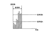
例えば、暗部分布偏り算出部32は、暗い画像である処理対象画像の明度と画素数とが図2に示す関係である場合に、処理対象画像の暗部のピークに近傍な平均明度を利用して、暗部を「A」と「B」とに分割(二分割)して画素数の分布偏りを算出する。なお、図2は、暗い画像であると判定された処理対象画像の明度と画素数との関係の例を示す図である。
For example, when the brightness of the processing target image that is a dark image and the number of pixels are in the relationship shown in FIG. 2, the dark part distribution
補正量決定部33は、暗部分布偏り算出部32によって算出された分布偏りに基づいて、処理対象画像に対する補正量を決定する。なお、補正量決定部33によって決定される補正カーブ(補正量)は、記憶部20に記憶されている。
The correction
上記した例で具体的に例を挙げると、補正量決定部33は、暗部分布偏り算出部32によって算出された暗部「A」の画素数の分布偏りと「Th2」とを比較する。なお、「Th2」は、例えば、処理対象画像全体の画素数の20%の値とするが、当該20%に限られるものではない。
Specifically, in the above example, the correction
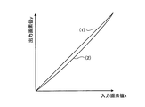
そして、補正量決定部33は、非常に暗い暗部である「A」の画素数が「Th2」よりも少ない場合に、(処理対象画像を従来技術で補正した際に)黒浮きの可能性があると判定する。続いて、補正量決定部33は、黒浮きの可能性があると判定した場合に、図3に示す補正カーブ(1)「y=x」、または、補正カーブ(2)「(式1)」を処理対象画像に対する補正量として決定する。なお、図3は、黒浮きの可能性がある場合に用いられる補正カーブの例を示す図である。
Then, when the number of pixels of “A”, which is a very dark dark part, is smaller than “Th2”, the correction
![]()
![]()
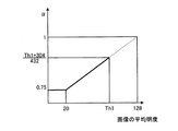
また、補正量決定部33は、非常に暗い暗部である「A」の画素数が「Th2」よりも多い場合に、(処理対象画像を従来技術で補正した際に)黒潰れの可能性があると判定する。そして、補正量決定部33は、黒潰れの可能性があると判定した場合に、図4に示す補正カーブ「(式2)」を処理対象画像に対する補正量として決定する。(式2)のパラメタ「α」の値は、図5に示すように、「Th1」によって変動する。なお、図4は、黒潰れの可能性がある場合に用いられる補正カーブの例を示す図であり、図5は、パラメタ値αの決定について説明するための図である。
Further, the correction

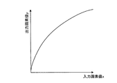
また、補正量決定部33は、画像判定部31によって通常の画像であると判定された処理対象画像(処理対象画像全体の平均明度が「Th1」よりも高い画像)に対して、図6に示す補正カーブ「(式3)」を処理対象画像に対する補正量として決定する。(式3)のパラメタ「α」の値は、図7に示すように、「Th1」によって変動する。図6に示す補正カーブは、上に凸である場合を示しているが、パラメタ「α」の値によって下に凸になる場合もある。なお、図6は、処理対象画像が通常の画像であると判定された場合に用いられる補正カーブの例を示す図であり、図7は、パラメタ値αの決定について説明するための図である。
In addition, the correction
つまり、補正量決定部33は、黒浮きの可能性があると判定した場合に、処理対象画像をさらに暗く、または、弱めに明るく補正し(または、補正しない)、黒潰れの可能性があると判定した場合に、処理対象画像を明るく補正する。言い換えると、補正量決定部33は、暗部「A」が黒浮きまたは黒潰れのどちらの可能性があるかに応じて補正量(補正カーブ)を決定する。なお、黒浮きまたは黒潰れの可能性の判定については、暗部「A」の画素数と「Th2」とを比較せずに、算出された画素の出現頻度の分布偏りから、処理対象画像の暗部の非常に暗い部分に画素が集まっているか否かによって判定することとしてもよい。
That is, when the correction
画像補正部34は、補正量決定部33によって決定された補正量を用いて、処理対象画像を補正して出力する。上記した例で具体的に例を挙げると、画像補正部34は、補正量決定部33によって決定された暗部に対する補正量を用いて、入力された処理対象画像を補正して出力する。
The image correcting unit 34 corrects and outputs the processing target image using the correction amount determined by the correction
[画像補正装置による処理全体の流れ]
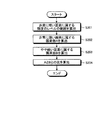
次に、図8を用いて、実施例1に係る画像補正装置10による処理全体の流れを説明する。図8は、実施例1に係る画像補正装置10による処理全体の流れを説明するためのフローチャートである。[Flow of overall processing by image correction device]
Next, the overall flow of processing performed by the
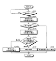
図8に示すように、画像補正装置10は、処理対象画像を受け付けた場合に(ステップS101肯定)、受け付けた処理対象画像のヒストグラムを算出する。そして、画像補正装置10は、算出されたヒストグラムを用いて、処理対象画像の各画素の明るさ度合いを示す明度から、処理対象画像全体の平均明度を算出する(ステップS102)。
As illustrated in FIG. 8, when the
続いて、画像補正装置10は、算出された処理対象画像全体の平均明度が閾値「Th1=50」以上であるか閾値未満であるかを判定する(ステップS103)。その後、画像補正装置10は、算出された平均明度が閾値以上である場合に、暗い画像ではないと判定し(ステップS103否定)、算出された平均明度が閾値未満である場合に、暗い画像であると判定する(ステップS103肯定)。
Subsequently, the
そして、画像補正装置10は、処理対象画像が暗い画像であると判定された場合に(ステップS103肯定)、当該暗い画像である処理対象画像において、算出された処理対象画像全体の平均明度よりも低い部分を示す暗部を分割して画素の出現頻度の分布偏りを算出する(ステップS104)。なお、暗部の分割については、処理対象画像の暗部のピークに近傍な平均明度を利用して、非常に暗い暗部である「A」とやや暗い暗部である「B」とに分割する。
Then, when it is determined that the processing target image is a dark image (Yes in step S103), the
続いて、画像補正装置10は、算出された暗部「A」の画素の出現頻度の分布偏りと「Th2」とを比較する。その後、画像補正装置10は、非常に暗い暗部である「A」の画素数が「Th2」よりも少ない場合に、黒浮きの可能性があると判定する(ステップS105黒浮き)。そして、画像補正装置10は、黒浮きの可能性があると判定した場合に、図3に示す補正カーブ(1)、または、補正カーブ(2)を処理対象画像に対する補正量として決定して補正を行う(ステップS106)。
Subsequently, the
また、画像補正装置10は、非常に暗い暗部である「A」の画素数が「Th2」よりも多い場合に、黒潰れの可能性があると判定する(ステップS105黒潰れ)。その後、画像補正装置10は、黒潰れの可能性があると判定した場合に、図4に示す補正カーブを処理対象画像に対する補正量として決定して補正を行う(ステップS107)。
Further, the
なお、画像補正装置10は、ステップS103において、処理対象画像全体の平均明度が「Th1」よりも高く、暗い画像ではないと判定された場合に(ステップS103否定)、図6に示す補正カーブを処理対象画像に対する補正量として決定して補正を行う(ステップS108)。
In step S103, the
[実施例1による効果]
上記したように、画像補正装置10は、処理対象画像の暗部における画素の出現頻度の分布偏りに基づいて、当該処理対象画像に対する補正量を決定するので、黒浮きまたは黒潰れを抑制することが可能である。[Effects of Example 1]
As described above, the
例えば、画像補正装置10は、処理対象画像を受け付けた場合に、受け付けた処理対象画像のヒストグラムを算出する。そして、画像補正装置10は、算出されたヒストグラムを用いて、処理対象画像の各画素の明るさ度合いを示す明度から、処理対象画像全体の平均明度を算出する。続いて、画像補正装置10は、算出された処理対象画像全体の平均明度が閾値「Th1=50」以上であるか閾値未満であるかを判定する。その後、画像補正装置10は、算出された平均明度が閾値未満である場合に、暗い画像であると判定する。そして、画像補正装置10は、処理対象画像が暗い画像であると判定された場合に、当該暗い画像である処理対象画像において、算出された処理対象画像全体の平均明度よりも低い部分を示す暗部を非常に暗い部分である「A」とやや暗い部分である「B」とに分割して画素の出現頻度の分布偏りを算出する。続いて、画像補正装置10は、算出された暗部「A」の画素の出現頻度の分布偏りと「Th2」(例えば、処理対象画像全体の画素数の20%)とを比較する。その後、画像補正装置10は、非常に暗い暗部である「A」の画素数が「Th2」よりも少ない場合に、黒浮きの可能性があると判定して補正量を決定し、決定された補正量を用いて補正する。また、画像補正装置10は、非常に暗い暗部である「A」の画素数が「Th2」よりも多い場合に、黒潰れの可能性があると判定して補正量を決定し、決定された補正量を用いて補正する。この結果、画像補正装置10は、黒浮きまたは黒潰れを抑制することができる。
For example, when receiving the processing target image, the
また、画像補正装置10は、処理対象画像から容易に得られる値を利用して、特に、暗い画像の暗部に対する補正量を決定するので、高速、低コストおよび高精度で補正することができる。
In addition, since the
ところで、上記実施例1では、画像暗部のピークに近傍な処理対象画像全体の平均明度を利用して、画素の出現頻度の分布偏りを算出する場合を説明したが、本発明はこれに限定されるものではなく、処理対象画像全体の平均明度に係数を掛けた値を利用して、画素の出現頻度の分布偏りを算出することもできる。 In the first embodiment, the case where the distribution bias of the appearance frequency of the pixels is calculated using the average brightness of the entire processing target image close to the peak of the dark portion of the image has been described. However, the present invention is not limited to this. Instead, it is possible to calculate the distribution bias of the appearance frequency of pixels by using a value obtained by multiplying the average brightness of the entire processing target image by a coefficient.
そこで、以下の実施例2では、図9を用いて、係数を利用して画像暗部のピークを算出する例について説明する。図9は、係数を利用して画像暗部のピークを算出する例を説明するための図である。なお、実施例2に係る画像補正装置10の各構成や一部の機能などについては、実施例1と同様であるためその説明を省略し、特に、実施例1とは異なる画像暗部のピーク算出処理を説明する。
Thus, in the second embodiment, an example in which the peak of an image dark portion is calculated using a coefficient will be described with reference to FIG. FIG. 9 is a diagram for explaining an example of calculating a peak of an image dark portion using a coefficient. The configuration and some functions of the
[実施例2に係る画像暗部のピーク算出処理]
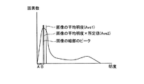
図9に示すように、画像補正装置10は、処理対象画像全体の平均明度「Ave1」を算出する。そして、画像補正装置10は、算出された平均明度「Ave1」に係数「0.8」を掛けて、画像暗部のピーク「Ave2」を算出する。その後、画像補正装置10は、算出された「Ave2」を利用して、暗部を「A」と「B」とに分割して画素の出現頻度の分布偏りを算出する。[Peak Calculation Processing of Image Dark Part According to Example 2]
As illustrated in FIG. 9, the
つまり、画像補正装置10は、図9に示すように、処理対象画像が暗い画像であっても、画素が暗部だけに集中していない場合に、平均明度の値が図2に示した処理対象画像よりも高くなるために、平均明度に係数を掛けて画像暗部のピークに近づける処理を行う。画素が暗部だけに集中していない暗い画像の例としては、夜間に撮影された花火の画像などが挙げられる。
That is, as shown in FIG. 9, the
[実施例2による効果]
上記したように、画像補正装置10は、画素が暗い部分だけに集中していない暗い画像である場合に、処理対象画像全体の平均明度を暗部のピークに近づける処理を行うので、処理対象画像に対する黒再現のための補正を高精度に実施することが可能である。[Effects of Example 2]
As described above, when the
つまり、画像補正装置10は、処理対象画像の暗部を補正する場合に、処理対象画像全体の平均明度に係数を掛けることにより、暗部の領域(暗部のピーク)を正確に抽出して精度良く補正することができる。
That is, when correcting the dark part of the processing target image, the
ところで、上記実施例1では、画像暗部のピークに近傍な処理対象画像全体の平均明度を利用して、画素の出現頻度の分布偏りを算出する場合を説明したが、本発明はこれに限定されるものではなく、画素値が高い画素を排除した部分の平均明度を利用して、画素の出現頻度の分布偏りを算出することもできる。 In the first embodiment, the case where the distribution bias of the appearance frequency of the pixels is calculated using the average brightness of the entire processing target image close to the peak of the dark portion of the image has been described. However, the present invention is not limited to this. Instead, it is also possible to calculate the distribution bias of the appearance frequency of the pixels by using the average brightness of the portion excluding the pixels having a high pixel value.
そこで、以下の実施例3では、図10を用いて、画素値が高い画素を排除した部分の平均明度を利用して、画像暗部のピークを算出する例について説明する。図10は、画素値が高い画素を排除した部分の平均明度を利用して、画像暗部のピークを算出する例を説明するための図である。なお、実施例3に係る画像補正装置10の各構成や一部の機能などについては、実施例1と同様であるためその説明を省略し、特に、実施例1とは異なる画像暗部のピーク算出処理を説明する。
Therefore, in Example 3 below, an example in which the peak of an image dark portion is calculated using the average brightness of a portion from which a pixel having a high pixel value is excluded will be described with reference to FIG. FIG. 10 is a diagram for explaining an example of calculating a peak of an image dark portion using an average brightness of a portion from which pixels having a high pixel value are excluded. The configuration and some functions of the
[実施例3に係る画像暗部のピーク算出]
図10に示すように、画像補正装置10は、処理対象画像の画素値(明度)「0〜128」の平均明度を算出する。そして、画像補正装置10は、算出された「0〜128」の平均明度を利用して、暗部を「A」と「B」とに分割して画素の出現頻度の分布偏りを算出する。[Peak Calculation of Image Dark Part According to Example 3]
As illustrated in FIG. 10, the
つまり、画像補正装置10は、図10に示すように、処理対象画像が暗い画像であっても、画素が暗部だけに集中していない場合に、平均明度の値が図2に示した処理対象画像よりも高くなるために、明るい部分の画素を排除した部分の平均明度を算出する処理を行う。なお、利用する画素値は、「0〜128」に限られるものではない。
That is, as shown in FIG. 10, the
[実施例3による効果]
上記したように、画像補正装置10は、画素が暗い部分だけに集中していない暗い画像である場合に、特に画像補正において重要となる暗部の領域をより正確に抽出するので、処理対象画像に対する黒再現のための補正をより高精度に実施することが可能である。[Effects of Example 3]
As described above, when the
つまり、画像補正装置10は、画像補正において重要となる黒再現のために、処理対象画像の明るい部分を排除した暗部の領域(暗部のピーク)を抽出するので、処理対象画像が暗い画像であると判定されれば、当該画像の特徴(例えば、明るい部分にも画素があるなど)にとらわれることなく補正することができる。
That is, the
ところで、上記実施例1では、処理対象画像の暗部を「A」と「B」とに分割(二等分)して画素の出現頻度の分布偏りを算出する場合を説明したが、本発明はこれに限定されるものではなく、処理対象画像の暗部を「A」と「B」とに分割して画素数の比により分布偏りを算出することもできる。 In the first embodiment, the case where the dark part of the processing target image is divided into “A” and “B” (bisected) to calculate the distribution frequency of the appearance frequency of pixels has been described. However, the present invention is not limited to this, and it is also possible to divide the dark part of the processing target image into “A” and “B” and calculate the distribution bias by the ratio of the number of pixels.
そこで、以下の実施例4では、図11を用いて、比を利用して暗部の分布偏りを算出する処理について説明する。図11は、比を利用して暗部の分布偏りを算出する処理の流れを説明するためのフローチャートである。なお、実施例4に係る画像補正装置10の各構成や一部の機能などについては、実施例1と同様であるためその説明を省略し、特に、実施例1とは異なる暗部の分布偏り算出処理を説明する。
Therefore, in the following fourth embodiment, a process for calculating the distribution deviation of the dark part using the ratio will be described with reference to FIG. FIG. 11 is a flowchart for explaining the flow of processing for calculating the distribution deviation of the dark part using the ratio. Note that the configuration and some functions of the
[実施例4に係る画像暗部の分布偏り算出]
図11に示すように、画像補正装置10は、算出された処理対象画像全体の平均明度を利用して、当該処理対象画像の非常に暗い画素に属する輝度のレベルの範囲(暗部)を算出する(ステップS201)。そして、画像補正装置10は、算出された暗部を非常に暗い暗部「A」とやや暗い暗部「B」とに分割して、暗部「A」の画素数と暗部「B」の画素数とを算出する(ステップS202、ステップS203)。[Calculation of distribution bias of image dark portion according to embodiment 4]
As illustrated in FIG. 11, the
続いて、画像補正装置10は、算出された暗部「A」の画素数と暗部「B」の画素数との比を算出して(ステップS204)、処理対象画像の暗部について、画素の出現頻度の分布偏りを算出する。その後、比を利用して分布偏りを算出した画像補正装置10は、暗部「A」の比率が暗部「B」よりも大きい場合に黒潰れの可能性があると判定し、暗部「A」の比率が暗部「B」よりも小さい場合に黒浮きの可能性があると判定する。
Subsequently, the
なお、画像暗部のピークの算出については、処理対象画像全体の平均明度だけでなく、実施例2のように、平均明度に係数を掛けた値を利用してもよいし、実施例3のように、画素値が高い画素を排除した部分の平均明度を利用することとしてもよい。 For calculating the peak in the dark part of the image, not only the average brightness of the entire processing target image but also a value obtained by multiplying the average brightness by a coefficient as in the second embodiment may be used, as in the third embodiment. In addition, it is possible to use the average brightness of the portion excluding pixels with high pixel values.
[実施例4による効果]
上記したように、画像補正装置10は、処理対象画像が暗い画像であると判定された場合に、暗部の分布偏りの比を利用して処理対象画像の補正量を決定することができる。[Effects of Example 4]
As described above, when it is determined that the processing target image is a dark image, the
さて、これまで本発明の実施例について説明したが、本発明は上述した実施例以外にも、種々の異なる形態にて実施されてよいものである。そこで、(1)画像判定処理に利用する統計量、(2)暗部の分割数、(3)暗部の分布偏り算出、(4)システム構成、(5)プログラムに区分けして異なる実施例を説明する。 Although the embodiments of the present invention have been described so far, the present invention may be implemented in various different forms other than the embodiments described above. Therefore, (1) statistics used for image determination processing, (2) number of dark part divisions, (3) dark part distribution bias calculation, (4) system configuration, and (5) programs are described as different embodiments. To do.
(1)画像判定処理に利用する統計量
上記実施例1〜上記実施例4では、処理対象画像全体の平均明度から当該処理対象画像が暗い画像であるか否かを判定する場合を説明したが、本発明はこれに限定されるものではなく、処理対象画像の全体的な分布偏りの統計量から当該処理対象画像が暗い画像であるか否かを判定することもできる。(1) Statistics used for image determination processing In the first to fourth embodiments, the case has been described in which it is determined whether or not the processing target image is a dark image from the average brightness of the entire processing target image. The present invention is not limited to this, and it is also possible to determine whether or not the processing target image is a dark image from the statistics of the overall distribution bias of the processing target image.
例えば、画像補正装置10は、処理対象画像全体の画素の最頻値や分散値などの全体的な分布偏りの統計量を算出して、当該処理対象画像が暗い画像であるか否かを判定する。つまり、処理対象画像が暗い画像であるか否かの判定に利用される統計量は、処理対象画像全体の平均明度だけでなく、処理対象画像全体の明るさ度合いがわかる統計量であれば何であってもよい。
For example, the
(2)暗部の分割数
また、上記実施例1〜上記実施例4では、処理対象画像の暗部を非常に暗い暗部「A」とやや暗い暗部「B」との二つに分割して分布偏りを算出する場合を説明したが、本発明はこれに限定されるものではなく、二つではない複数領域に分割して分布偏りを算出することもできる。(2) Number of Dark Part Divisions In the first to fourth examples, the dark part of the image to be processed is divided into two parts, a very dark dark part “A” and a slightly darker dark part “B”. However, the present invention is not limited to this, and the distribution bias can be calculated by dividing into a plurality of areas other than two.
例えば、画像補正装置10は、処理対象画像の暗部を三つや四つなどに分割して分布偏りを算出する。つまり、画像補正装置10は、処理対象画像の暗部を複数領域に分割して分布偏りを算出するので、処理対象画像暗部の補正をより高精度に実施することができる。
For example, the
(3)暗部の分布偏り算出
上記実施例1〜上記実施例4では、処理対象画像暗部の分布偏りの算出において、画素の出現頻度や画素数の比を利用する場合を説明したが、本発明はこれに限定されるものではなく、数学的に分布を示す指標を利用することもできる。(3) Calculation of dark portion distribution bias In the first to fourth embodiments, the case where the pixel appearance frequency and the ratio of the number of pixels are used in the calculation of the distribution bias of the processing target image dark portion has been described. However, the present invention is not limited to this, and an index indicating a mathematical distribution can also be used.
例えば、画像補正装置10は、処理対象画像全体の平均の偏差に基づいて特性を算出する「Skewness」や分散値などを利用して、処理対象画像暗部の分布偏りを算出する。つまり、暗部の分布偏りに利用される計算は、処理対象画像暗部の絶対数や比などだけでなく、処理対象画像暗部の画素数の度合いがわかる統計量であれば何であってもよい。
For example, the
(4)システム構成
また、上記文書中や図面中で示した処理手順、制御手順、具体的名称、各種のデータやパラメタを含む情報(例えば、図1に示した記憶部20に保持される補正カーブなど)については、特記する場合を除いて任意に変更することができる。(4) System Configuration In addition, the processing procedure, control procedure, specific name, information including various data and parameters shown in the document and drawings (for example, corrections held in the
また、図示した各装置の各構成要素は機能概念的なものであり、必ずしも物理的に図示の如く構成されていることを要しない。すなわち、各装置の分散・統合の具体的形態は図示のものに限られず、例えば、補正量決定部33と画像補正部34とを、処理対象画像に対する補正量を決定し、決定された補正量を用いて補正して出力する「画像補正部」に統合するなど、その全部または一部を、各種の負荷や使用状況などに応じて、任意の単位で機能的または物理的に分散・統合して構成することができる。さらに、各装置にて行われる各処理機能は、その全部または任意の一部が、CPUおよび当該CPUにて解析実行されるプログラムにて実現され、あるいは、ワイヤードロジックによるハードウェアとして実現され得る。
Further, each component of each illustrated apparatus is functionally conceptual, and does not necessarily need to be physically configured as illustrated. That is, the specific form of distribution / integration of each device is not limited to the illustrated one. For example, the correction
(5)プログラム
ところで、上記実施例では、ハードウェアロジックによって各種の処理を実現する場合を説明したが、本発明はこれに限定されるものではなく、あらかじめ用意されたプログラムをコンピュータで実行することによって実現するようにしてもよい。そこで、以下では、図12を用いて、上記の実施例に示した画像補正装置10と同様の機能を有する画像補正プログラムを実行するコンピュータの一例を説明する。図12は、画像補正プログラムを実行するコンピュータを示す図である。(5) Program In the above embodiment, the case where various processes are realized by hardware logic has been described. However, the present invention is not limited to this, and a program prepared in advance is executed by a computer. It may be realized by. Therefore, in the following, an example of a computer that executes an image correction program having the same function as that of the
図12に示すように、画像補正装置としてのコンピュータ110は、HDD130、CPU140、ROM150およびRAM160をバス180などで接続される。
As shown in FIG. 12, a
ROM150には、上記の実施例1に示した画像補正装置10と同様の機能を発揮する画像補正プログラム、つまり、図12に示すように画像判定プログラム150aと、暗部分布偏り算出プログラム150bと、補正量決定プログラム150cとが、あらかじめ記憶されている。なお、これらのプログラム150a〜プログラム150cについては、図1に示した画像補正装置10の各構成要素と同様、適宜統合または、分散してもよい。
The
そして、CPU140がこれらのプログラム150a〜プログラム150cをROM150から読み出して実行することで、図12に示すように、プログラム150a〜プログラム150cは、画像判定プロセス140aと、暗部分布偏り算出プロセス140bと、補正量決定プロセス140cとして機能するようになる。なお、プロセス140a〜プロセス140cは、図1に示した、画像判定部31と、暗部分布偏り算出部32と、補正量決定部33とに対応する。
Then, the
そして、CPU140はRAM160に記録されたデータに基づいて画像補正プログラムを実行する。
Then, the
なお、上記した各プログラム150a〜プログラム150cについては、必ずしも最初からROM150に記憶させておく必要はなく、例えば、コンピュータ110に挿入されるフレキシブルディスク(FD)、CD−ROM、DVDディスク、光磁気ディスク、ICカードなどの「可搬用の物理媒体」、またはコンピュータ110の内外に備えられるHDDなどの「固定用の物理媒体」、さらには公衆回線、インターネット、LAN、WANなどを介してコンピュータ110に接続される「他のコンピュータ(またはサーバ)」などに各プログラムを記憶させておき、コンピュータ110がこれらから各プログラムを読み出して実行するようにしてもよい。
The above-described
Claims (14)
前記画像判定手段によって前記処理対象画像が暗い画像であると判定された場合に、当該暗い画像である処理対象画像において、第一の値よりも低い部分を示す暗部を該暗部のピークに近傍な平均明度を利用して複数の領域に分割し、該複数の領域のうち少なくとも一つの領域の画素の出現頻度の分布偏りを算出する暗部分布偏り算出手段と、
前記暗部分布偏り算出手段によって算出された分布偏りに基づいて、前記処理対象画像に対する補正量を決定する補正量決定手段と、
を備えたことを特徴とする画像補正装置。Image determining means for determining whether or not the processing target image is a dark image based on a pixel value of each pixel of the processing target image;
When the image determination unit determines that the processing target image is a dark image, in the processing target image that is the dark image, a dark portion indicating a lower portion than the first value is close to the peak of the dark portion. A dark part distribution bias calculating unit that divides into a plurality of regions using average brightness and calculates a distribution bias of appearance frequencies of pixels in at least one region of the plurality of regions ;
Correction amount determining means for determining a correction amount for the processing target image based on the distribution bias calculated by the dark part distribution bias calculating means;
An image correction apparatus comprising:
前記画像判定手順によって前記処理対象画像が暗い画像であると判定された場合に、当該暗い画像である処理対象画像において、第一の値よりも低い部分を示す暗部を該暗部のピークに近傍な平均明度を利用して複数の領域に分割し、該複数の領域のうち少なくとも一つの領域の画素の出現頻度の分布偏りを算出する暗部分布偏り算出手順と、
前記暗部分布偏り算出手順によって算出された分布偏りに基づいて、前記処理対象画像に対する補正量を決定する補正量決定手順と、
をコンピュータに実行させることを特徴とする画像補正プログラム。An image determination procedure for determining whether or not the processing target image is a dark image based on a pixel value of each pixel of the processing target image;
When it is determined by the image determination procedure that the processing target image is a dark image, in the processing target image that is the dark image, a dark portion indicating a lower portion than the first value is close to the peak of the dark portion. A dark part distribution bias calculation procedure that divides into a plurality of regions using average brightness and calculates a distribution bias of appearance frequency of pixels in at least one region of the plurality of regions ;
A correction amount determination procedure for determining a correction amount for the processing target image based on the distribution bias calculated by the dark part distribution bias calculation procedure;
An image correction program for causing a computer to execute.
前記画像判定工程によって前記処理対象画像が暗い画像であると判定された場合に、当該暗い画像である処理対象画像において、第一の値よりも低い部分を示す暗部を該暗部のピークに近傍な平均明度を利用して複数の領域に分割し、該複数の領域のうち少なくとも一つの領域の画素の出現頻度の分布偏りを算出する暗部分布偏り算出工程と、
前記暗部分布偏り算出工程によって算出された分布偏りに基づいて、前記処理対象画像に対する補正量を決定する補正量決定工程と、
を含んだことを特徴とする画像補正方法。An image determination step of determining whether or not the processing target image is a dark image based on a pixel value of each pixel of the processing target image;
When it is determined by the image determination step that the processing target image is a dark image, in the processing target image that is the dark image, a dark portion that indicates a lower portion than the first value is close to the peak of the dark portion. A dark part distribution bias calculating step of dividing the plurality of regions using the average brightness and calculating a distribution bias of the appearance frequency of pixels in at least one region of the plurality of regions ;
A correction amount determining step for determining a correction amount for the processing target image based on the distribution bias calculated by the dark portion distribution bias calculating step;
An image correction method comprising:
Applications Claiming Priority (1)
| Application Number | Priority Date | Filing Date | Title |
|---|---|---|---|
| PCT/JP2008/060910 WO2009150749A1 (en) | 2008-06-13 | 2008-06-13 | Picture correcting device, picture correcting program and picture correcting method |
Publications (2)
| Publication Number | Publication Date |
|---|---|
| JPWO2009150749A1 JPWO2009150749A1 (en) | 2011-11-10 |
| JP5110161B2 true JP5110161B2 (en) | 2012-12-26 |
Family
ID=41416470
Family Applications (1)
| Application Number | Title | Priority Date | Filing Date |
|---|---|---|---|
| JP2010516700A Expired - Fee Related JP5110161B2 (en) | 2008-06-13 | 2008-06-13 | Image correction apparatus, image correction program, and image correction method |
Country Status (3)
| Country | Link |
|---|---|
| EP (1) | EP2290945B1 (en) |
| JP (1) | JP5110161B2 (en) |
| WO (1) | WO2009150749A1 (en) |
Families Citing this family (3)
| Publication number | Priority date | Publication date | Assignee | Title |
|---|---|---|---|---|
| TWI567707B (en) * | 2014-08-08 | 2017-01-21 | 明基電通股份有限公司 | Image adjusting method and related display |
| CN105513566A (en) * | 2016-01-25 | 2016-04-20 | 明基电通有限公司 | Image adjusting method of executing optimal adjustment according to different environments and displayer |
| CN114051098B (en) * | 2021-11-23 | 2023-05-30 | 河南牧业经济学院 | Intelligent visual image acquisition method and platform |
Citations (2)
| Publication number | Priority date | Publication date | Assignee | Title |
|---|---|---|---|---|
| JPH04110920A (en) * | 1990-08-31 | 1992-04-13 | Sanyo Electric Co Ltd | Gradation correcting circuit |
| JP2007189575A (en) * | 2006-01-16 | 2007-07-26 | Matsushita Electric Ind Co Ltd | Automatic video processing system and automatic video processing method |
Family Cites Families (6)
| Publication number | Priority date | Publication date | Assignee | Title |
|---|---|---|---|---|
| JPH06332399A (en) | 1993-05-19 | 1994-12-02 | Fujitsu General Ltd | Method for controlling electronic display and device therefor |
| TWI285872B (en) * | 1999-05-10 | 2007-08-21 | Matsushita Electric Ind Co Ltd | Image display device and method for displaying image |
| US6633343B2 (en) * | 2000-03-14 | 2003-10-14 | Matsushita Electric Industrial Co., Ltd. | Dynamic gamma correction apparatus |
| KR100592385B1 (en) * | 2003-11-17 | 2006-06-22 | 엘지.필립스 엘시디 주식회사 | Driving Method and Driving Device of Liquid Crystal Display |
| JP4277773B2 (en) * | 2004-09-21 | 2009-06-10 | 株式会社日立製作所 | Video display device |
| JP4854431B2 (en) * | 2006-08-31 | 2012-01-18 | キヤノン株式会社 | Image processing apparatus and method |
-
2008
- 2008-06-13 EP EP08777221.6A patent/EP2290945B1/en not_active Not-in-force
- 2008-06-13 WO PCT/JP2008/060910 patent/WO2009150749A1/en active Application Filing
- 2008-06-13 JP JP2010516700A patent/JP5110161B2/en not_active Expired - Fee Related
Patent Citations (2)
| Publication number | Priority date | Publication date | Assignee | Title |
|---|---|---|---|---|
| JPH04110920A (en) * | 1990-08-31 | 1992-04-13 | Sanyo Electric Co Ltd | Gradation correcting circuit |
| JP2007189575A (en) * | 2006-01-16 | 2007-07-26 | Matsushita Electric Ind Co Ltd | Automatic video processing system and automatic video processing method |
Also Published As
| Publication number | Publication date |
|---|---|
| EP2290945A4 (en) | 2011-08-03 |
| JPWO2009150749A1 (en) | 2011-11-10 |
| EP2290945A1 (en) | 2011-03-02 |
| WO2009150749A1 (en) | 2009-12-17 |
| EP2290945B1 (en) | 2016-08-31 |
Similar Documents
| Publication | Publication Date | Title |
|---|---|---|
| Lin et al. | Multi-scale retinex improvement for nighttime image enhancement | |
| US11113795B2 (en) | Image edge processing method, electronic device, and computer readable storage medium | |
| US8131098B2 (en) | Image processing device, image processing method, image processing system, program, storage medium, and integrated circuit | |
| US9165346B2 (en) | Method and apparatus for reducing image noise | |
| US20060204124A1 (en) | Image processing apparatus for correcting contrast of image | |
| KR102211592B1 (en) | Electronic device for processing image and method thereof | |
| US20180232867A1 (en) | Electronic device performing image conversion, and method thereof | |
| US8369648B2 (en) | Image correction apparatus and image correction method | |
| EP2293241B1 (en) | Method and apparatus for image processing | |
| US20090087092A1 (en) | Histogram stretching apparatus and histogram stretching method for enhancing contrast of image | |
| RU2496250C1 (en) | Image processing apparatus and method | |
| US8295639B2 (en) | Image correction apparatus, image correction method, and image correction program | |
| EP3306915B1 (en) | Method and apparatus for controlling image data | |
| US20160071253A1 (en) | Method and apparatus for image enhancement | |
| JP5648849B2 (en) | Image processing apparatus and image processing method | |
| US20120070084A1 (en) | Image processing apparatus, image processing method, and image processing program | |
| CN108090887B (en) | Video image processing method and device | |
| US20110110595A1 (en) | Image correction apparatus and method for eliminating lighting component | |
| JP5110161B2 (en) | Image correction apparatus, image correction program, and image correction method | |
| US10438323B2 (en) | Image brightness correction and noise suppression method, device, and recording medium for storing image processing program | |
| US20160110854A1 (en) | Image processing apparatus, image processing method, and program | |
| JP5245991B2 (en) | BRIGHTNESS CORRECTION PROGRAM, BRIGHTNESS CORRECTION METHOD, AND BRIGHTNESS CORRECTION DEVICE | |
| US8351729B2 (en) | Apparatus, method, and program for image correction | |
| US8570337B2 (en) | Color corrector, video display device, and color correction method | |
| JP5312171B2 (en) | Image processing apparatus and method |
Legal Events
| Date | Code | Title | Description |
|---|---|---|---|
| A131 | Notification of reasons for refusal |
Free format text: JAPANESE INTERMEDIATE CODE: A131 Effective date: 20120417 |
|
| A521 | Request for written amendment filed |
Free format text: JAPANESE INTERMEDIATE CODE: A523 Effective date: 20120524 |
|
| A02 | Decision of refusal |
Free format text: JAPANESE INTERMEDIATE CODE: A02 Effective date: 20120619 |
|
| A521 | Request for written amendment filed |
Free format text: JAPANESE INTERMEDIATE CODE: A523 Effective date: 20120731 |
|
| A911 | Transfer to examiner for re-examination before appeal (zenchi) |
Free format text: JAPANESE INTERMEDIATE CODE: A911 Effective date: 20120820 |
|
| TRDD | Decision of grant or rejection written | ||
| A01 | Written decision to grant a patent or to grant a registration (utility model) |
Free format text: JAPANESE INTERMEDIATE CODE: A01 Effective date: 20120911 |
|
| A01 | Written decision to grant a patent or to grant a registration (utility model) |
Free format text: JAPANESE INTERMEDIATE CODE: A01 |
|
| A61 | First payment of annual fees (during grant procedure) |
Free format text: JAPANESE INTERMEDIATE CODE: A61 Effective date: 20120924 |
|
| FPAY | Renewal fee payment (event date is renewal date of database) |
Free format text: PAYMENT UNTIL: 20151019 Year of fee payment: 3 |
|
| R150 | Certificate of patent or registration of utility model |
Ref document number: 5110161 Country of ref document: JP Free format text: JAPANESE INTERMEDIATE CODE: R150 Free format text: JAPANESE INTERMEDIATE CODE: R150 |
|
| LAPS | Cancellation because of no payment of annual fees |