EP2290945B1 - Picture correcting device, picture correcting program and picture correcting method - Google Patents
Picture correcting device, picture correcting program and picture correcting method Download PDFInfo
- Publication number
- EP2290945B1 EP2290945B1 EP08777221.6A EP08777221A EP2290945B1 EP 2290945 B1 EP2290945 B1 EP 2290945B1 EP 08777221 A EP08777221 A EP 08777221A EP 2290945 B1 EP2290945 B1 EP 2290945B1
- Authority
- EP
- European Patent Office
- Prior art keywords
- image
- dark
- processing target
- target image
- dark area
- Prior art date
- Legal status (The legal status is an assumption and is not a legal conclusion. Google has not performed a legal analysis and makes no representation as to the accuracy of the status listed.)
- Not-in-force
Links
Images


Classifications
-
- H—ELECTRICITY
- H04—ELECTRIC COMMUNICATION TECHNIQUE
- H04N—PICTORIAL COMMUNICATION, e.g. TELEVISION
- H04N5/00—Details of television systems
- H04N5/14—Picture signal circuitry for video frequency region
- H04N5/16—Circuitry for reinsertion of dc and slowly varying components of signal; Circuitry for preservation of black or white level
-
- H—ELECTRICITY
- H04—ELECTRIC COMMUNICATION TECHNIQUE
- H04N—PICTORIAL COMMUNICATION, e.g. TELEVISION
- H04N21/00—Selective content distribution, e.g. interactive television or video on demand [VOD]
- H04N21/40—Client devices specifically adapted for the reception of or interaction with content, e.g. set-top-box [STB]; Operations thereof
- H04N21/43—Processing of content or additional data, e.g. demultiplexing additional data from a digital video stream; Elementary client operations, e.g. monitoring of home network or synchronising decoder's clock; Client middleware
- H04N21/431—Generation of visual interfaces for content selection or interaction; Content or additional data rendering
- H04N21/4318—Generation of visual interfaces for content selection or interaction; Content or additional data rendering by altering the content in the rendering process, e.g. blanking, blurring or masking an image region
-
- H—ELECTRICITY
- H04—ELECTRIC COMMUNICATION TECHNIQUE
- H04N—PICTORIAL COMMUNICATION, e.g. TELEVISION
- H04N21/00—Selective content distribution, e.g. interactive television or video on demand [VOD]
- H04N21/40—Client devices specifically adapted for the reception of or interaction with content, e.g. set-top-box [STB]; Operations thereof
- H04N21/43—Processing of content or additional data, e.g. demultiplexing additional data from a digital video stream; Elementary client operations, e.g. monitoring of home network or synchronising decoder's clock; Client middleware
- H04N21/44—Processing of video elementary streams, e.g. splicing a video clip retrieved from local storage with an incoming video stream, rendering scenes according to MPEG-4 scene graphs
- H04N21/44008—Processing of video elementary streams, e.g. splicing a video clip retrieved from local storage with an incoming video stream, rendering scenes according to MPEG-4 scene graphs involving operations for analysing video streams, e.g. detecting features or characteristics in the video stream
-
- H—ELECTRICITY
- H04—ELECTRIC COMMUNICATION TECHNIQUE
- H04N—PICTORIAL COMMUNICATION, e.g. TELEVISION
- H04N5/00—Details of television systems
- H04N5/14—Picture signal circuitry for video frequency region
- H04N5/20—Circuitry for controlling amplitude response
-
- H—ELECTRICITY
- H04—ELECTRIC COMMUNICATION TECHNIQUE
- H04N—PICTORIAL COMMUNICATION, e.g. TELEVISION
- H04N5/00—Details of television systems
- H04N5/44—Receiver circuitry for the reception of television signals according to analogue transmission standards
- H04N5/57—Control of contrast or brightness
Definitions
- the present invention relates to an image correcting apparatus, an image correcting program, and an image correcting method.
- a visual quality of an image in a reproduction of a dark scene (a dark area) in a digital television depends on how a block color is output. Therefore, it has been conventionally demanded in a correction of a digital image to suppress a black floating phenomenon which is caused when a dark area becomes bright and a black defacement phenomenon which is caused when a dark area becomes darker.
- a technique for correcting a dark image there is a technique of correcting, based on an average brightness of an image, a darker image into a brighter image.
- a general dynamic range correction technique for example, there is a technique of making a correction via a linear interpolation in which pixels the number of which is approximately 0.1% to 1.0% of an entire image in the darkest area are made level "zero".
- Patent Document 1 discloses a technique of generating a histogram of an entire image and calculating a correction amount in a black range which is a dark area of the image as illustrated in FIG. 13 based on the number of distribution of pixels which are not more than a reference value A and on the number of distribution of pixels which are not less than a reference value B.
- FIG. 13 is a view for explaining a conventional technique of correcting a dark image.
- Patent Document 2 discloses a technique for performing gamma correction processing when there are a plurality of characteristic areas, each of which is characterized by the high frequency in a luminance histogram to improve the impression of contrast.
- a luminance characteristic detector detects the luminance of an input image signal and a microcomputer calculates an APL (average picture level) and a luminance histogram of an input image signal.
- a gamma correction circuit performs the gamma correction processing in response to the luminosity of the input image signal by use of the result of the calculation carried out by the microcomputer. Then, if there are a plurality of characteristic areas, each of which is characterized by the high frequency in the luminance histogram, a characteristic emphasis circuit performs greyscale extension processing for the plurality of characteristic areas.
- Patent Document 3 discloses an automatic video processing system provided with: a pedestal clamp part for clamping a video signal at a pedestal level; an A/D converting part for converting a pedestal clamped video signal into a digital signal; an APL (average picture luminance) detecting part for acquiring an APL for a video signal one field period from A/D converted discrete data; an APL comparing part for comparing the detected APL with a reference value; a histogram operating part for acquiring a histogram (frequency distribution) of luminance constituting the video signal one field; a histogram comparing part for comparing the acquired histogram with the reference value; a control part for determining whether a signal is set up on the basis of results obtained from the APL comparing part and the histogram comparing part; an operating part for performing gradation correction of a set up signal so as to decrease a black level and simultaneously keep a peak level uniform; a video signal processing part for processing an inputted video signal; and a display part for displaying a video signal
- the conventional technique described above has a problem that the black floating phenomenon or the black defacement phenomenon cannot be suppressed.
- Patent Document 1 includes a possibility of causing the black floating phenomenon when pixels in a black range concentrate especially in a bright range (when the number of pixels having a higher brightness in the black range is large) as illustrated in FIG. 14-1 . Moreover, Patent Document 1 includes a possibility of causing the black defacement phenomenon when pixels in the black range concentrate especially in a dark range (when the number of pixels having a lower brightness is large) as illustrated in FIG. 14-2 .
- Patent Document 1 has a possibility of causing the black floating phenomenon or the black defacement phenomenon in at least one image. As a result of this, the black floating phenomenon or the black defacement phenomenon cannot be suppressed in the conventional technique described above.
- FIG. 14-1 is a view illustrating a dark area pixels of which concentrate in a bright range in an image
- FIG. 14-2 is a view illustrating a dark area pixels of which concentrate in a dark range in an image.
- the present invention is achieved to solve the problems in the above-described conventional technique and an object of the present invention is to provide an image correcting apparatus, an image correcting program, and an image correcting method which enable suppression of the black floating phenomenon or the black defacement phenomenon in correcting a dark image.
- an image correcting apparatus disclosed in the application requires to include an image determining unit operable to determine based on a pixel value of each pixel of a processing target image whether or not the processing target image is a dark image; a dark area distribution balance calculator operable to calculate, when the processing target image is determined by the image determining unit to be the dark image, a distribution balance of a frequency of appearance of pixels in a dark area of the processing target image, the dark area being an area where the pixels have a smaller pixel value than a first value, divide the dark area of the processing target image into a very dark area and a slightly dark area using an average brightness adjacent to a peak of the dark area, and calculate a distribution balance of a frequency of appearance of pixels in the very dark area based on the number of pixels; and a correction amount determining unit operable to determine a correction amount with respect to the processing target image based on the distribution balance calculated by the dark area distribution balance calculator.
- the image correcting apparatus has an advantage that the black floating phenomenon or the black defacement phenomenon can be suppressed in correcting a dark image.
- the image correcting apparatus to be disclosed in the present invention is arranged in an inside of a digital television and the like and outputs after correction a processing target image to be input.
- the image correcting apparatus can be applied not only to a digital television but also to one segment (one-segment broadcasting) terminal, a personal computer (PC), an image data relaying device, and the like.
- the image correcting apparatus determines whether or not the processing target image is a dark image based on a pixel value of each pixel of the processing target image.
- the image correcting apparatus calculates a distribution balance of a frequency of appearance of pixels in a dark area which indicates an area having a smaller value than a first value in the processing target image as a dark image. Then, the image correcting apparatus determines a correction amount with respect to the processing target image based on the calculated distribution balance. After that, the image correcting apparatus corrects the image by the determined correction amount.
- the image correcting apparatus calculates a distribution balance of a frequency of appearance of pixels in a dark area when the input processing target image is a dark image. Then, the image correcting apparatus determines that there is a possibility of causing the black defacement phenomenon when the calculated distribution balance of the dark area concentrates in a very dark range, and that there is a possibility of causing the black floating phenomenon when the calculated distribution balance of the dark area concentrates in a slightly dark range. Next, the image correcting apparatus makes a correction after determining a correction amount (a correction curve) according to the processing target image which is determined to have the possibility of causing the black floating phenomenon or the black defacement phenomenon.
- the image correcting apparatus can suppress the black floating phenomenon or the black defacement phenomenon as a result of being able to determine a correction amount with respect to a processing target image according to a distribution balance of a frequency of appearance of pixels in a dark area in the processing target image, compared to the conventional technique in which a correction amount is determined according to the number of pixels in a dark area in an image and an entirety of the dark area in the image is corrected by a definite measure.
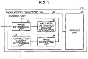
- FIG. 1 is a view of a configuration of the image correcting apparatus according to the first embodiment.
- an image correcting apparatus 10 is provided with a storage unit 20 and a control unit 30 and outputs after correction a processing target image to be input.
- the storage unit 20 stores data necessary for various processes performed by the control unit 30 and results of various processes performed by the control unit 30.
- the storage unit 20 stores a correction curve necessary for an image correcting process performed by the control unit 30 and a result of the image correcting process performed by the control unit 30.
- the control unit 30 is specifically provided with, in addition to an internal memory which stores a control program, a program specifying various process procedures, and necessary data, an image determining unit 31, a dark area distribution balance calculator 32, a correction amount determining unit 33, and an image correcting unit 34 and performs various processes by these units.
- the image determining unit 31 determines whether or not the processing target image is a dark image based on a pixel value of each pixel of the processing target image.
- the image determining unit 31 accepts a processing target image to be input to calculate a histogram of the accepted processing target image.
- the histogram may be calculated from values for red, green, and blue (RGB) of the processing target image or may be calculated after calculating intensity values from the RGB values of the processing target image.
- the image determining unit 31 calculates an average brightness of an entirety of the processing target image from a brightness indicating a degree of brightness of each pixel of the processing target image by using the calculated histogram. For example, the calculated average brightness becomes low when the distribution balance of the processing target image concentrates in a dark range and becomes high when the distribution balance of the processing target image concentrates in a bright range.
- the threshold value "Th1" used for determining whether or not the processing target image is a dark image is not limited to "50".
- the dark area distribution balance calculator 32 calculates a distribution balance of a frequency of appearance of pixels in a dark area indicating an area having a smaller value than the first value in the processing target image as a dark image.
- the dark area distribution balance calculator 32 when the processing target image is determined by the image determining unit 31 to be a dark image, divides the dark area indicating an area the brightness of which is lower than the calculated average brightness of the entirety of the processing target image in the processing target image as a dark image and calculates a distribution balance of a frequency of appearance of pixels.
- the dark area distribution balance calculator 32 uses an average brightness adjacent to a peak of the dark area of the processing target image, divides the dark area into "A" and "B" (two parts), and calculate a distribution balance of the number of pixels.
- FIG. 2 illustrates an example of a relation between the brightness and the number of pixels of the processing target image which is determined to be a dark image.
- the correction amount determining unit 33 determines a correction amount with respect to the processing target image based on the distribution balance calculated by the dark area distribution balance calculator 32.
- a correction curve (correction amount) determined by the correction amount determining unit 33 is stored in the storage unit 20.
- the correction amount determining unit 33 compares the distribution balance, calculated by the dark area distribution balance calculator 32, of the number of pixels in the dark area "A" to a threshold value "Th2".
- the threshold value 'Th2 is, for example, configured to be a value equivalent to 20% of the number of pixels in the entirety of the processing target image, the value is not limited to the equivalent to 20%.
- FIG. 3 illustrates an example of correction curves to be used when there is a possibility of causing a black floating phenomenon.
- the correction amount determining unit 33 determines that there is a possibility of causing (in correcting the processing target image in the conventional technique) the black defacement phenomenon. Then, the correction amount determining unit 33, in the case of determining that there is a possibility of causing the black defacement phenomenon, determines a correction curve expressed by "expression (2)", which is illustrated in FIG. 4 , as a correction amount for the processing target image.
- expression (2) which is illustrated in FIG. 4
- a value for a parameter " ⁇ " in expression (2) varies depending on the threshold value "Th1" as illustrated in FIG. 5 .
- FIG. 4 illustrates an example of a correction curve to be used when there is a possibility of causing a black defacement phenomenon
- FIG. 5 is a view for explaining a determination of the parameter value ⁇ .
- the correction amount determining unit 33 determines a correction curve expressed by "expression (3)", which is illustrated in FIG. 6 , as a correction amount for the processing target image with respect to the processing target image which is determined by the image determining unit 31 to be a normal image (image the average brightness of the entirety of which is higher than the threshold value "Th1").
- a value for a parameter " ⁇ " in expression (3) varies depending on the threshold value "Th1" as illustrated in FIG. 7 .
- the correction curve illustrated in FIG. 6 represents a case of being convex, there is a case of being conclave depending on the value of the parameter " ⁇ ".
- FIG. 6 illustrates an example of a correction curve to be used when the processing target image is determined to be a normal image
- FIG. 7 is a view for explaining a determination of the parameter value ⁇ .
- the correction amount determining unit 33 makes a correction of the processing target image into a darker image or a slightly brighter image (or makes no correction) in the case of determining that the possibility of causing the black floating phenomenon is present and makes a correction into a brighter image in the case of determining that the possibility of causing the black defacement phenomenon is present.
- the correction amount determining unit 33 determines a correction amount (a correction curve) depending on which possibility of causing the black floating phenomenon or the black defacement phenomenon is present in the dark area "A".
- the determination of the possibility of the black floating phenomenon or the black defacement phenomenon may be made depending on whether or not, based on the calculated distribution balance of the frequency of appearance of the pixels, the pixels concentrate in a very dark range of the dark area of the processing target image without comparing the number of pixels in the dark area "A" to the threshold value "Th2".
- the image correcting unit 34 uses the correction amount determined by the correction amount determining unit 33 to correct and output the processing target image. To give a specific example further in the above example, the image correcting unit 34 uses the correction amount for the dark area determined by the correction amount determining unit 33 to correct and output the input processing target image.
- FIG. 8 is a flowchart for explaining a flow of an entire process performed by the image correcting apparatus 10 according to the first embodiment.
- the image correcting apparatus 10 when accepting a processing target image ("Yes" in step S101), calculates a histogram of the accepted processing target image.
- the image correcting apparatus 10 uses the calculated histogram to calculate an average brightness of the entirety of the processing target image from a brightness indicating a degree of brightness of each pixel of the processing target image (step S102).
- the image correcting apparatus 10 divides the dark area indicating an area lower than the calculated average brightness of the entirety of the processing target image in the processing target image as a dark image to calculate a distribution balance of a frequency of appearance of pixels (step S104).
- an average brightness adjacent to a peak of the dark area of the processing target image is used to divide the dark area into a range "A" which is very dark area and a range "B” which is a slightly dark area.
- the image correcting apparatus then compares the calculated distribution balance of pixels in the dark area "A" to the threshold value "Th2". After that, the image correcting apparatus 10 determines that there is a possibility of causing the black floating phenomenon when the number of pixels of the very dark area "A" is smaller than the threshold value "Th2" ("BLACK FLOATING PHENOMENON" at step S105). Then, the image correcting apparatus 10 determines the correction curve (1) or the correction curve (2) illustrated in FIG. 3 as a correction amount for the processing target image and performs a correction when the possibility of causing the black floating phenomenon is determined to be present (step S106).
- the image correcting apparatus determines that there is a possibility of causing the black defacement phenomenon ("BLACK DEFACEMENET PHENOMENON" at step S105). After that, the image correcting apparatus 10 determines the correction curve illustrated in FIG. 4 as a correction amount for the processing target image and performs a correction when the possibility of causing the black defacement phenomenon is determined to be present (step S107).
- the image correcting apparatus 10 determines the correction curve illustrated in FIG. 6 as a correction amount for the processing target image and performs a correction (step S108) .
- the black floating phenomenon or the black defacement phenomenon can be suppressed since the image correcting apparatus 10 determines a correction amount for the processing target image based on the distribution balance of a frequency of appearance of pixels in the dark area of the processing target image.
- the image correcting apparatus 10 divides, into a range "A" which is a very dark area and a range "B" which is a slightly dark area, the dark area indicating an area lower than the calculated average brightness of the entirety of the processing target image in the processing target image as a dark image and calculates a distribution balance of a frequency of appearance of pixels.
- the image correcting apparatus 10 compares the calculated distribution balance of the frequency of appearance of pixels in the dark area "A" to the threshold value "Th2" (the value is equivalent to 20% of the number of pixels of the entirety of the processing target image, for example).
- the image correcting apparatus 10 determines that there is a possibility of causing the black floating phenomenon, determines a correction amount, and makes a correction by using the determined correction amount.
- the image correcting apparatus 10 determines that there is a possibility of causing the black defacement phenomenon, determines a correction amount, and makes a correction by using the determined correction amount.
- the image correcting apparatus 10 can suppress the black floating phenomenon or the black defacement phenomenon.
- the image correcting apparatus 10 can make a correction at high speed, at low cost, and with a high degree of accuracy since the image correcting apparatus 10 uses values which can be easily obtained from the processing target image and especially determines a correction amount for a dark area of a dark image.
- the present invention is not limited thereto and a value obtained by multiplying the average brightness of the entirety of the processing target image by a coefficient can be used to calculate a distribution balance of a frequency of appearance of pixels.
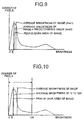
- FIG. 9 is a view for explaining the example of calculating a peak of a dark area in an image by using a coefficient.
- each constituent and a part of functions of an image correcting apparatus 10 according to the second embodiment are the same as those in the first embodiment, the explanation for them will be omitted and a process, different from the first embodiment, of calculating a peak of a dark area in an image will be explained specifically.
- the image correcting apparatus 10 calculates an average brightness "Ave1" of the entirety of the processing target image.
- the image correcting apparatus 10 multiplies the calculated average brightness "Ave1” by a coefficient "0.8” to calculate a peak "Ave2" of the dark area of the image.
- the image correcting apparatus 10 uses the calculated peak "Ave2" to calculate a distribution balance of a frequency of appearance of pixels through a division of a dark area into "A" and "B".
- the image correcting apparatus 10 performs a process of multiplying the average brightness by the coefficient to approximate the peak of the dark area of the image.
- Examples of a dark image in which pixels do not concentrate only in the dark range may include an image of a firework captured at night.
- the image correcting apparatus 10 can make a correction for reproducing shades of black with respect to the processing target image with a high degree of accuracy since the image correcting apparatus 10 performs the process of making the average brightness of the entirety of the processing target image approximate the peak in the dark area in the case of a dark image in which pixels do not concentrate only in the dark range.
- the image correcting apparatus 10 can extract a range of a dark area (peak of a dark area) accurately and make a correction with a high degree of accuracy by multiplying the average brightness of the entirety of the processing target image by the coefficient in correcting the dark area of the processing target image.
- the present invention is not limited thereto and a distribution balance of a frequency of appearance of pixels can be calculated by using an average brightness of an area remained after excluding a pixel having a large pixel value.
- FIG. 10 is a view for explaining the example of calculating a peak in a dark area of an image by using an average brightness of an area remained after excluding a pixel having a large pixel value.
- each constituent and a part of functions of an image correcting apparatus 10 according to the third embodiment are the same as those in the first embodiment, the explanation for them will be omitted and a process, different from the first embodiment, of calculating a peak in a dark area of an image will be explained specifically.
- the image correcting apparatus 10 calculates an average brightness of pixel values (brightness) "0 to 128" of the processing target image.
- the image correcting apparatus 10 uses the calculated average brightness of the "0 to 128" to calculate a distribution balance of a frequency of appearance of pixels through a division of a dark area into "A" and "B” .
- the image correcting apparatus 10 performs a process of calculating an average brightness of an area remained after excluding a pixel in a bright area.
- the pixel values to be used are not limited to "0 to 128".
- the image correcting apparatus 10 can make a correction for reproducing shades of black in the processing target image with a higher degree of accuracy since the image correcting apparatus 10 accurately extracts a range of a dark area which is especially of significance in an image correction in the case of a dark image in which pixels do not concentrate only in a dark range.
- the image correcting apparatus 10 can extract a range of a dark area (peak of a dark area) remained after excluding a bright area in the processing target image for reproducing shades of black which is of significance in an image correction and thereby can make a correction irrespective of characteristics (for example, pixels are present in bright range and so on) of an image as long as a processing target image is determined to be a dark image.
- FIG. 11 is a flowchart for explaining a flow of a process of calculating a distribution balance in a dark area by using a ratio.
- the explanation for them will be omitted and a process, different from the first embodiment, of calculating a distribution balance in a dark area will be explained specifically.
- the image correcting apparatus 10 calculates a level range of a brightness of a very dark pixel (dark area) of the processing target image by using the calculated average brightness of the entirety of the processing target image (step S201).
- the image correcting apparatus 10 then divides the calculated dark area into a very dark area "A” and a slightly dark area “B” and calculates the number of pixels in the dark area "A” and the number of pixels in the dark area "B” (step S202 and step S203).
- the image correcting apparatus 10 calculates a ratio of the calculated number of pixels in the dark area "A” to the calculated number of pixels in the dark area "B” (step S204) and calculates a distribution balance of a frequency of appearance of pixels with respect to the dark area of the processing target image. After that, the image correcting apparatus 10 having calculated the distribution balance by using the ratio determines that there is a possibility of causing the black defacement phenomenon when the ratio of the dark area "A" is higher than that of the dark area "B” and determines that there is a possibility of causing the black floating phenomenon when the ratio of the dark area "A" is lower than that of the dark area "B".
- a value obtained by multiplying an average brightness by a coefficient may be used similarly to the second embodiment and an average brightness of an area remained after excluding a pixel having a large pixel value may be used similarly to the third embodiment instead of an average brightness of an entirety of a processing target image.
- the image correcting apparatus 10 can determine a correction amount of a processing target image by using a ratio of a distribution balance in a dark area when the processing target image is determined to be a dark image.
- the present invention is not limited thereto and whether or not the processing target image is a dark image can be determined from an amount of statistics of an overall distribution balance of the processing target image.
- the image correcting apparatus 10 calculates an amount of statistics of an overall distribution balance such as a mode value and a variance value of pixels of the entirety of the processing target image to determine whether or not the processing target image is a dark image.
- the amount of statistics used for the determination of whether or not the processing target image is a dark image may be, without being limited to the average brightness of the entirety of the processing target image, anything which indicates a degree of brightness of the entirety of the processing target image.
- the image correcting apparatus 10 calculates a distribution balance by dividing a dark area of the processing target image into three, four, or the like.
- the image correcting apparatus 10 can make a correction of a dark area of the processing target image with a higher degree of accuracy since the image correcting apparatus 10 calculates a distribution balance by dividing the dark area of the processing target image into a plurality of areas.
- the image correcting apparatus 10 calculates a distribution balance of a dark area of the processing target image by using a "skewness" or a variance value for calculating characteristics based on an average deviation of the entirety of the processing target image.
- the calculation used for a distribution balance of a dark area may be, without being limited to an absolute value, a ratio, and the like of a dark area of the processing target image, any amount of statistics which indicate a degree of the number of pixels in the dark area of the processing target image.
- constituents of each device illustrated are only exemplary and explanatory on a functional and conceptual basis, and are not necessarily required to be configured physically as illustrated.
- a specific disintegration/integration of each device is not limited to the illustrated modes and all or a part thereof can be configured by functionally or physically applying disintegration/integration in a given unit according to load of various kinds, a status of use, and the like; for example, the correction amount determining unit 33 and the image correcting unit 34 are integrated as an "image correcting unit" which determines a correction amount with respect to the processing target image and outputs after making a correction by using the determined correction amount.
- all or a part of each processing function performed by each device may be realized by a CPU and a program analyzed and executed by the CPU, or may be realized as a hardware of a wired logic.
- FIG. 12 illustrates a computer which executes an image correcting program.
- a computer 110 as an image correcting apparatus is connected to a hard disk drive (HDD) 130, a central processing unit (CPU) 140, a read-only memory (ROM) 150, and a random access memory (RAM) 160 via a bus 180 and the like.
- HDD hard disk drive
- CPU central processing unit
- ROM read-only memory
- RAM random access memory
- an image correcting program which exercises functions similar to the image correcting apparatus 10 illustrated in the first embodiment described above, i.e., an image determining program 150a, a dark area distribution balance calculating program 150b, and a correction amount determining program 150c are stored in advance as illustrated in FIG. 12 .
- the programs 150a to 150c may be arbitrarily integrated or disintegrated similarly to each constituent of the image correcting apparatus 10 illustrated in FIG. 1 .
- the CPU 140 reads out from the ROM 150 and executes the programs 150a to 150c, so that the programs 150a to 150c come to function respectively as an image determining process 140a, a dark area distribution balance calculating process 140b, and a correction amount determining process 140c as illustrated in FIG. 12 .
- the processes 140a to 140c correspond to the image determining unit 31, the dark area distribution balance calculator 32, and the correction amount determining unit 33 illustrated in FIG. 1 , respectively.
- the CPU 140 executes the image correcting program based on the data recorded in the RAM 160.
- each of the programs 150a to 150c described above is not necessarily required to be stored in the ROM 150 from the beginning and may be stored in "portable physical media” to be inserted into the computer 110 such as a flexible disk (FD), a CD-ROM, a DVD, an optical magnetic disk, and an IC card; "fixed physical media” such as a HDD provided in an inside or an outside of the computer 110; and "other computers (or a server)" to be connected to the computer 110 via a public line, the Internet, a LAN, a WAN, and the like, and the computer 110 may reads out therefrom and executes each of the programs.
- "portable physical media” such as a flexible disk (FD), a CD-ROM, a DVD, an optical magnetic disk, and an IC card
- fixed physical media such as a HDD provided in an inside or an outside of the computer 110
- other computers or a server
Description
- The present invention relates to an image correcting apparatus, an image correcting program, and an image correcting method.
- In general, a visual quality of an image in a reproduction of a dark scene (a dark area) in a digital television depends on how a block color is output. Therefore, it has been conventionally demanded in a correction of a digital image to suppress a black floating phenomenon which is caused when a dark area becomes bright and a black defacement phenomenon which is caused when a dark area becomes darker.
- In response, there have been various disclosed techniques for correcting a dark image in recent years.
- For example as a technique for correcting a dark image, there is a technique of correcting, based on an average brightness of an image, a darker image into a brighter image. Besides, as a general dynamic range correction technique for example, there is a technique of making a correction via a linear interpolation in which pixels the number of which is approximately 0.1% to 1.0% of an entire image in the darkest area are made level "zero".
- In addition,
Patent Document 1, for example, discloses a technique of generating a histogram of an entire image and calculating a correction amount in a black range which is a dark area of the image as illustrated inFIG. 13 based on the number of distribution of pixels which are not more than a reference value A and on the number of distribution of pixels which are not less than a reference value B.FIG. 13 is a view for explaining a conventional technique of correcting a dark image. -
Patent Document 2 discloses a technique for performing gamma correction processing when there are a plurality of characteristic areas, each of which is characterized by the high frequency in a luminance histogram to improve the impression of contrast. A luminance characteristic detector detects the luminance of an input image signal and a microcomputer calculates an APL (average picture level) and a luminance histogram of an input image signal. A gamma correction circuit performs the gamma correction processing in response to the luminosity of the input image signal by use of the result of the calculation carried out by the microcomputer. Then, if there are a plurality of characteristic areas, each of which is characterized by the high frequency in the luminance histogram, a characteristic emphasis circuit performs greyscale extension processing for the plurality of characteristic areas. - Patent Document 3 discloses an automatic video processing system provided with: a pedestal clamp part for clamping a video signal at a pedestal level; an A/D converting part for converting a pedestal clamped video signal into a digital signal; an APL (average picture luminance) detecting part for acquiring an APL for a video signal one field period from A/D converted discrete data; an APL comparing part for comparing the detected APL with a reference value; a histogram operating part for acquiring a histogram (frequency distribution) of luminance constituting the video signal one field; a histogram comparing part for comparing the acquired histogram with the reference value; a control part for determining whether a signal is set up on the basis of results obtained from the APL comparing part and the histogram comparing part; an operating part for performing gradation correction of a set up signal so as to decrease a black level and simultaneously keep a peak level uniform; a video signal processing part for processing an inputted video signal; and a display part for displaying a video signal subjected to optimum video signal processing.
-
- Patent Document 1: Japanese Laid-open Patent Publication No.
06-332399 - Patent Document 2:
GB2418316A - Patent Document 3:
JP2007/189575A - However, the conventional technique described above has a problem that the black floating phenomenon or the black defacement phenomenon cannot be suppressed.
- Specifically, there is a possibility, in the technique of correcting an image based on an average brightness of an entirety of an image, of causing the black floating phenomenon depending on the image since the image determined to be a dark image is corrected at any time to be bright by a definite measure. Besides, in correcting an image of a significant darkness, the dark image is not corrected because the dark image already contains pixels of level "zero" not less than 1.0% while there is an advantage in correcting an image of a normal brightness in the general dynamic range correction technique.
- Furthermore,
Patent Document 1 includes a possibility of causing the black floating phenomenon when pixels in a black range concentrate especially in a bright range (when the number of pixels having a higher brightness in the black range is large) as illustrated inFIG. 14-1 . Moreover,Patent Document 1 includes a possibility of causing the black defacement phenomenon when pixels in the black range concentrate especially in a dark range (when the number of pixels having a lower brightness is large) as illustrated inFIG. 14-2 . - In other words, for calculating a correction amount similarly with respect to an image illustrated in
FIG. 14-1 or an image illustrated inFIG. 14-2 ,Patent Document 1 has a possibility of causing the black floating phenomenon or the black defacement phenomenon in at least one image. As a result of this, the black floating phenomenon or the black defacement phenomenon cannot be suppressed in the conventional technique described above. Here,FIG. 14-1 is a view illustrating a dark area pixels of which concentrate in a bright range in an image andFIG. 14-2 is a view illustrating a dark area pixels of which concentrate in a dark range in an image. - The present invention is achieved to solve the problems in the above-described conventional technique and an object of the present invention is to provide an image correcting apparatus, an image correcting program, and an image correcting method which enable suppression of the black floating phenomenon or the black defacement phenomenon in correcting a dark image.
- To solve the problems described above and achieve the object, an image correcting apparatus disclosed in the application requires to include an image determining unit operable to determine based on a pixel value of each pixel of a processing target image whether or not the processing target image is a dark image; a dark area distribution balance calculator operable to calculate, when the processing target image is determined by the image determining unit to be the dark image, a distribution balance of a frequency of appearance of pixels in a dark area of the processing target image, the dark area being an area where the pixels have a smaller pixel value than a first value, divide the dark area of the processing target image into a very dark area and a slightly dark area using an average brightness adjacent to a peak of the dark area, and calculate a distribution balance of a frequency of appearance of pixels in the very dark area based on the number of pixels; and a correction amount determining unit operable to determine a correction amount with respect to the processing target image based on the distribution balance calculated by the dark area distribution balance calculator.
- The image correcting apparatus according to the present invention has an advantage that the black floating phenomenon or the black defacement phenomenon can be suppressed in correcting a dark image.
-
-
FIG. 1 is a view of a configuration of an image correcting apparatus according to a first embodiment. -
FIG. 2 illustrates an example of a relation between brightness and the number of pixels of a processing target image which is determined to be a dark image. -
FIG. 3 illustrates an example of correction curves to be used when there is a possibility of causing a black floating phenomenon. -
FIG. 4 illustrates an example of a correction curve to be used when there is a possibility of causing a black defacement phenomenon. -
FIG. 5 is a view for explaining a determination of a parameter value α. -
FIG. 6 illustrates an example of a correction curve to be used when a processing target image is determined to be a normal image. -
FIG. 7 is a view for explaining a determination of a parameter value α. -
FIG. 8 is a flowchart for explaining a flow of an entire process performed by the image correcting apparatus according to the first embodiment. -
FIG. 9 is a view for explaining an example of calculating a peak in a dark area of an image by using a coefficient. -
FIG. 10 is a view for explaining an example of calculating a peak in a dark area of an image by using an average brightness of an area remained after excluding a pixel having a large pixel value. -
FIG. 11 is a flowchart for explaining a flow of a process of calculating a distribution balance in a dark area by using a ratio. -
FIG. 12 illustrates a computer which executes an image correcting program. -
FIG. 13 is a view for explaining a technique of correcting a dark image according to a conventional technique. -
FIG. 14-1 is a view illustrating a dark area pixels of which concentrate in a bright range in an image. -
FIG. 14-2 is a view illustrating a dark area pixels of which concentrate in a dark range in an image. - 10 Image correcting apparatus
- 20 Storage unit
- 30 Control unit
- 31 Image determining unit
- 32 Dark area distribution balance calculator
- 33 Correction amount determining unit
- 34 Image correcting unit
- Exemplary embodiments of an image correcting apparatus according to the present invention will be explained in detail below with reference to the accompanying drawings.
- A brief overview of an image correcting apparatus according to a first embodiment will be explained first. The image correcting apparatus to be disclosed in the present invention is arranged in an inside of a digital television and the like and outputs after correction a processing target image to be input. The image correcting apparatus can be applied not only to a digital television but also to one segment (one-segment broadcasting) terminal, a personal computer (PC), an image data relaying device, and the like.
- In the above-described configuration, the image correcting apparatus determines whether or not the processing target image is a dark image based on a pixel value of each pixel of the processing target image. When the processing target image is determined to be a dark image, the image correcting apparatus then calculates a distribution balance of a frequency of appearance of pixels in a dark area which indicates an area having a smaller value than a first value in the processing target image as a dark image. Then, the image correcting apparatus determines a correction amount with respect to the processing target image based on the calculated distribution balance. After that, the image correcting apparatus corrects the image by the determined correction amount.
- Specifically, the image correcting apparatus calculates a distribution balance of a frequency of appearance of pixels in a dark area when the input processing target image is a dark image. Then, the image correcting apparatus determines that there is a possibility of causing the black defacement phenomenon when the calculated distribution balance of the dark area concentrates in a very dark range, and that there is a possibility of causing the black floating phenomenon when the calculated distribution balance of the dark area concentrates in a slightly dark range. Next, the image correcting apparatus makes a correction after determining a correction amount (a correction curve) according to the processing target image which is determined to have the possibility of causing the black floating phenomenon or the black defacement phenomenon.
- As described above, the image correcting apparatus can suppress the black floating phenomenon or the black defacement phenomenon as a result of being able to determine a correction amount with respect to a processing target image according to a distribution balance of a frequency of appearance of pixels in a dark area in the processing target image, compared to the conventional technique in which a correction amount is determined according to the number of pixels in a dark area in an image and an entirety of the dark area in the image is corrected by a definite measure.
- A configuration of the image correcting apparatus according to the first embodiment will be explained next with reference to
FIG. 1. FIG. 1 is a view of a configuration of the image correcting apparatus according to the first embodiment. As illustrated inFIG. 1 , animage correcting apparatus 10 is provided with astorage unit 20 and a control unit 30 and outputs after correction a processing target image to be input. - The
storage unit 20 stores data necessary for various processes performed by the control unit 30 and results of various processes performed by the control unit 30. For example, thestorage unit 20 stores a correction curve necessary for an image correcting process performed by the control unit 30 and a result of the image correcting process performed by the control unit 30. - The control unit 30 is specifically provided with, in addition to an internal memory which stores a control program, a program specifying various process procedures, and necessary data, an image determining unit 31, a dark area
distribution balance calculator 32, a correctionamount determining unit 33, and animage correcting unit 34 and performs various processes by these units. - The image determining unit 31 determines whether or not the processing target image is a dark image based on a pixel value of each pixel of the processing target image. To give a specific example, the image determining unit 31 accepts a processing target image to be input to calculate a histogram of the accepted processing target image. The histogram may be calculated from values for red, green, and blue (RGB) of the processing target image or may be calculated after calculating intensity values from the RGB values of the processing target image.
- The image determining unit 31 then calculates an average brightness of an entirety of the processing target image from a brightness indicating a degree of brightness of each pixel of the processing target image by using the calculated histogram. For example, the calculated average brightness becomes low when the distribution balance of the processing target image concentrates in a dark range and becomes high when the distribution balance of the processing target image concentrates in a bright range.
- After that, the image determining unit 31 determines whether the calculated average brightness of the entirety of the processing target image is equal to or more than a threshold value "Th1 = 50" or less than the threshold value. The image determining unit 31 then determines that the processing target image is not a dark image when the calculated average brightness is equal to or more than the threshold value and that the processing target image is a dark image when the calculated average brightness is less than the threshold value. Here, the threshold value "Th1" used for determining whether or not the processing target image is a dark image is not limited to "50".
- When the processing target image is determined by the image determining unit 31 to be a dark image, the dark area
distribution balance calculator 32 calculates a distribution balance of a frequency of appearance of pixels in a dark area indicating an area having a smaller value than the first value in the processing target image as a dark image. - To give a specific example further in the above example, the dark area
distribution balance calculator 32, when the processing target image is determined by the image determining unit 31 to be a dark image, divides the dark area indicating an area the brightness of which is lower than the calculated average brightness of the entirety of the processing target image in the processing target image as a dark image and calculates a distribution balance of a frequency of appearance of pixels. - For example, when the brightness and the number of pixels of the processing target image as a dark image are in a relation illustrated in
FIG. 2 , the dark areadistribution balance calculator 32 uses an average brightness adjacent to a peak of the dark area of the processing target image, divides the dark area into "A" and "B" (two parts), and calculate a distribution balance of the number of pixels.FIG. 2 illustrates an example of a relation between the brightness and the number of pixels of the processing target image which is determined to be a dark image. - The correction
amount determining unit 33 determines a correction amount with respect to the processing target image based on the distribution balance calculated by the dark areadistribution balance calculator 32. Here, a correction curve (correction amount) determined by the correctionamount determining unit 33 is stored in thestorage unit 20. - To give a specific example further in the above example, the correction
amount determining unit 33 compares the distribution balance, calculated by the dark areadistribution balance calculator 32, of the number of pixels in the dark area "A" to a threshold value "Th2". Here, while the threshold value 'Th2" is, for example, configured to be a value equivalent to 20% of the number of pixels in the entirety of the processing target image, the value is not limited to the equivalent to 20%. - Then, the correction
amount determining unit 33 determines that there is a possibility of causing (in correcting the processing target image in the conventional technique) the black floating phenomenon when the number of pixels of the area "A" which is a very dark area is smaller than the threshold value "Th2". Subsequently, the correctionamount determining unit 33, in the case of determining that there is a possibility of causing the black floating phenomenon, determines a correction curve (1) expressed by "y = x" or a correction curve (2) expressed by "expression (1)", which are illustrated inFIG. 3 , as a correction amount for the processing target image. Here,FIG. 3 illustrates an example of correction curves to be used when there is a possibility of causing a black floating phenomenon. -

- When the number of pixels of the area "A" which is a very dark area is larger than the threshold value "Th2", the correction
amount determining unit 33 determines that there is a possibility of causing (in correcting the processing target image in the conventional technique) the black defacement phenomenon. Then, the correctionamount determining unit 33, in the case of determining that there is a possibility of causing the black defacement phenomenon, determines a correction curve expressed by "expression (2)", which is illustrated inFIG. 4 , as a correction amount for the processing target image. A value for a parameter "α" in expression (2) varies depending on the threshold value "Th1" as illustrated inFIG. 5 . Here,FIG. 4 illustrates an example of a correction curve to be used when there is a possibility of causing a black defacement phenomenon andFIG. 5 is a view for explaining a determination of the parameter value α. -

- In addition, the correction
amount determining unit 33 determines a correction curve expressed by "expression (3)", which is illustrated inFIG. 6 , as a correction amount for the processing target image with respect to the processing target image which is determined by the image determining unit 31 to be a normal image (image the average brightness of the entirety of which is higher than the threshold value "Th1"). A value for a parameter "α" in expression (3) varies depending on the threshold value "Th1" as illustrated inFIG. 7 . Though the correction curve illustrated inFIG. 6 represents a case of being convex, there is a case of being conclave depending on the value of the parameter "α". Here,FIG. 6 illustrates an example of a correction curve to be used when the processing target image is determined to be a normal image andFIG. 7 is a view for explaining a determination of the parameter value α. -

- To put it simply, the correction
amount determining unit 33 makes a correction of the processing target image into a darker image or a slightly brighter image (or makes no correction) in the case of determining that the possibility of causing the black floating phenomenon is present and makes a correction into a brighter image in the case of determining that the possibility of causing the black defacement phenomenon is present. In other words, the correctionamount determining unit 33 determines a correction amount (a correction curve) depending on which possibility of causing the black floating phenomenon or the black defacement phenomenon is present in the dark area "A". Here, the determination of the possibility of the black floating phenomenon or the black defacement phenomenon may be made depending on whether or not, based on the calculated distribution balance of the frequency of appearance of the pixels, the pixels concentrate in a very dark range of the dark area of the processing target image without comparing the number of pixels in the dark area "A" to the threshold value "Th2". - The
image correcting unit 34 uses the correction amount determined by the correctionamount determining unit 33 to correct and output the processing target image. To give a specific example further in the above example, theimage correcting unit 34 uses the correction amount for the dark area determined by the correctionamount determining unit 33 to correct and output the input processing target image. - Next, a flow of an entire process performed by the
image correcting apparatus 10 according to the first embodiment will be explained with reference toFIG. 8. FIG. 8 is a flowchart for explaining a flow of an entire process performed by theimage correcting apparatus 10 according to the first embodiment. - As illustrated in
FIG. 8 , theimage correcting apparatus 10, when accepting a processing target image ("Yes" in step S101), calculates a histogram of the accepted processing target image. Theimage correcting apparatus 10 then uses the calculated histogram to calculate an average brightness of the entirety of the processing target image from a brightness indicating a degree of brightness of each pixel of the processing target image (step S102). - Subsequently, the
image correcting apparatus 10 determines whether the calculated average brightness of the entirety of the processing target image is equal to or more than the threshold value "Th1 = 50" or less than the threshold value (step s103). After that, theimage correcting apparatus 10 determines that the processing target image is not a dark image ("No" at step S103) when the calculated average brightness is equal to or more than the threshold value, and that the processing target image is a dark image ("Yes" at step S103) when the calculated average brightness is less than the threshold value. - When the processing target image is determined to be a dark image ("Yes" at step S103), the
image correcting apparatus 10 divides the dark area indicating an area lower than the calculated average brightness of the entirety of the processing target image in the processing target image as a dark image to calculate a distribution balance of a frequency of appearance of pixels (step S104). Here, an average brightness adjacent to a peak of the dark area of the processing target image is used to divide the dark area into a range "A" which is very dark area and a range "B" which is a slightly dark area. - The image correcting apparatus then compares the calculated distribution balance of pixels in the dark area "A" to the threshold value "Th2". After that, the
image correcting apparatus 10 determines that there is a possibility of causing the black floating phenomenon when the number of pixels of the very dark area "A" is smaller than the threshold value "Th2" ("BLACK FLOATING PHENOMENON" at step S105). Then, theimage correcting apparatus 10 determines the correction curve (1) or the correction curve (2) illustrated inFIG. 3 as a correction amount for the processing target image and performs a correction when the possibility of causing the black floating phenomenon is determined to be present (step S106). - Besides, when the number of the very dark area "A" is larger than the threshold value "Th2", the image correcting apparatus determines that there is a possibility of causing the black defacement phenomenon ("BLACK DEFACEMENET PHENOMENON" at step S105). After that, the
image correcting apparatus 10 determines the correction curve illustrated inFIG. 4 as a correction amount for the processing target image and performs a correction when the possibility of causing the black defacement phenomenon is determined to be present (step S107). - When the average brightness of the entirety of the processing target image is higher than the threshold value "Th1" and the processing target image is determined not to be a dark image ("No" at step S103), the
image correcting apparatus 10 determines the correction curve illustrated inFIG. 6 as a correction amount for the processing target image and performs a correction (step S108) . - As described above, the black floating phenomenon or the black defacement phenomenon can be suppressed since the
image correcting apparatus 10 determines a correction amount for the processing target image based on the distribution balance of a frequency of appearance of pixels in the dark area of the processing target image. - For example, the
image correcting apparatus 10, when accepting a processing target image, calculates a histogram of the accepted processing target image. Then, theimage correcting apparatus 10 calculates an average brightness of an entirety of the processing target image from a brightness indicating a degree of brightness of each pixel of the processing target image by using the calculated histogram. Subsequently, theimage correcting apparatus 10 determines whether the calculated average brightness of the entirety of the processing target image is equal to or more than the threshold value "Th1 = 50" or less than the threshold value. After that, theimage correcting apparatus 10 determines that the processing target image is a dark image when the calculated average brightness is less than the threshold value. When the processing target image is determined to be a dark image, theimage correcting apparatus 10 divides, into a range "A" which is a very dark area and a range "B" which is a slightly dark area, the dark area indicating an area lower than the calculated average brightness of the entirety of the processing target image in the processing target image as a dark image and calculates a distribution balance of a frequency of appearance of pixels. Next, theimage correcting apparatus 10 compares the calculated distribution balance of the frequency of appearance of pixels in the dark area "A" to the threshold value "Th2" (the value is equivalent to 20% of the number of pixels of the entirety of the processing target image, for example). After that, when the number of pixels of the very dark area "A" is smaller than the threshold value "Th2", theimage correcting apparatus 10 determines that there is a possibility of causing the black floating phenomenon, determines a correction amount, and makes a correction by using the determined correction amount. When the number of pixels of the very dark area "A" is larger than the threshold value "Th2", theimage correcting apparatus 10 determines that there is a possibility of causing the black defacement phenomenon, determines a correction amount, and makes a correction by using the determined correction amount. As. a result, theimage correcting apparatus 10 can suppress the black floating phenomenon or the black defacement phenomenon. - Moreover, the
image correcting apparatus 10 can make a correction at high speed, at low cost, and with a high degree of accuracy since theimage correcting apparatus 10 uses values which can be easily obtained from the processing target image and especially determines a correction amount for a dark area of a dark image. - While the case of using an average brightness, adjacent to a peak in a dark area of an image, of an entirety of a processing target image and calculating a distribution balance of a frequency of appearance of pixels is explained in the first embodiment described above, the present invention is not limited thereto and a value obtained by multiplying the average brightness of the entirety of the processing target image by a coefficient can be used to calculate a distribution balance of a frequency of appearance of pixels.
- In a second embodiment below, an example of calculating a peak of a dark area in an image by using a coefficient will be explained with reference to
FIG. 9. FIG. 9 is a view for explaining the example of calculating a peak of a dark area in an image by using a coefficient. Here, since each constituent and a part of functions of animage correcting apparatus 10 according to the second embodiment are the same as those in the first embodiment, the explanation for them will be omitted and a process, different from the first embodiment, of calculating a peak of a dark area in an image will be explained specifically. - As illustrated in
FIG. 9 , theimage correcting apparatus 10 calculates an average brightness "Ave1" of the entirety of the processing target image. Theimage correcting apparatus 10 multiplies the calculated average brightness "Ave1" by a coefficient "0.8" to calculate a peak "Ave2" of the dark area of the image. After that, theimage correcting apparatus 10 uses the calculated peak "Ave2" to calculate a distribution balance of a frequency of appearance of pixels through a division of a dark area into "A" and "B". - In other words, since a value of the average brightness becomes larger than the processing target image in
FIG. 2 when pixels do not concentrate only in the dark range as illustrated inFIG. 9 even though the processing target image is a dark image, theimage correcting apparatus 10 performs a process of multiplying the average brightness by the coefficient to approximate the peak of the dark area of the image. Examples of a dark image in which pixels do not concentrate only in the dark range may include an image of a firework captured at night. - As described above, the
image correcting apparatus 10 can make a correction for reproducing shades of black with respect to the processing target image with a high degree of accuracy since theimage correcting apparatus 10 performs the process of making the average brightness of the entirety of the processing target image approximate the peak in the dark area in the case of a dark image in which pixels do not concentrate only in the dark range. - In other words, the
image correcting apparatus 10 can extract a range of a dark area (peak of a dark area) accurately and make a correction with a high degree of accuracy by multiplying the average brightness of the entirety of the processing target image by the coefficient in correcting the dark area of the processing target image. - While the case of calculating a distribution balance of a frequency of appearance of pixels by using an average brightness, adjacent to a peak in a dark area of an image, of an entirety of a processing target image is explained in the first embodiment, the present invention is not limited thereto and a distribution balance of a frequency of appearance of pixels can be calculated by using an average brightness of an area remained after excluding a pixel having a large pixel value.
- So, an example of calculating a peak in a dark area of an image by using an average brightness of an area remained after excluding a pixel having a large pixel value will be explained in a third embodiment below with reference to
FIG. 10. FIG. 10 is a view for explaining the example of calculating a peak in a dark area of an image by using an average brightness of an area remained after excluding a pixel having a large pixel value. Here, since each constituent and a part of functions of animage correcting apparatus 10 according to the third embodiment are the same as those in the first embodiment, the explanation for them will be omitted and a process, different from the first embodiment, of calculating a peak in a dark area of an image will be explained specifically. - As illustrated in
FIG. 10 , theimage correcting apparatus 10 calculates an average brightness of pixel values (brightness) "0 to 128" of the processing target image. Theimage correcting apparatus 10 then uses the calculated average brightness of the "0 to 128" to calculate a distribution balance of a frequency of appearance of pixels through a division of a dark area into "A" and "B". - In other words, since a value of the average brightness becomes larger than the processing target image in
FIG. 2 when pixels do not concentrate only in a dark range as illustrated inFIG. 10 even though the processing target image is a dark image, theimage correcting apparatus 10 performs a process of calculating an average brightness of an area remained after excluding a pixel in a bright area. Here, the pixel values to be used are not limited to "0 to 128". - As described above, the
image correcting apparatus 10 can make a correction for reproducing shades of black in the processing target image with a higher degree of accuracy since theimage correcting apparatus 10 accurately extracts a range of a dark area which is especially of significance in an image correction in the case of a dark image in which pixels do not concentrate only in a dark range. - In other words, the
image correcting apparatus 10 can extract a range of a dark area (peak of a dark area) remained after excluding a bright area in the processing target image for reproducing shades of black which is of significance in an image correction and thereby can make a correction irrespective of characteristics (for example, pixels are present in bright range and so on) of an image as long as a processing target image is determined to be a dark image. - While the case of calculating a distribution balance of a frequency of appearance of pixels by dividing a dark area of a processing target image into "A" and "B" (two equal parts) is explained in the first embodiment described above, the present invention is not limited thereto and a distribution balance can be calculated depending on a ratio of the number of pixels after the division of the dark area of the processing target image into "A" and "B".
- A process of calculating a distribution balance of a dark area by using a ratio will be explained in a fourth embodiment below with reference to
FIG. 11. FIG. 11 is a flowchart for explaining a flow of a process of calculating a distribution balance in a dark area by using a ratio. Here, since each constituent and a part of functions of animage correcting apparatus 10 according to the fourth embodiment are the same as those in the first embodiment, the explanation for them will be omitted and a process, different from the first embodiment, of calculating a distribution balance in a dark area will be explained specifically. - As illustrated in
FIG. 11 , theimage correcting apparatus 10 calculates a level range of a brightness of a very dark pixel (dark area) of the processing target image by using the calculated average brightness of the entirety of the processing target image (step S201). Theimage correcting apparatus 10 then divides the calculated dark area into a very dark area "A" and a slightly dark area "B" and calculates the number of pixels in the dark area "A" and the number of pixels in the dark area "B" (step S202 and step S203). - Subsequently, the
image correcting apparatus 10 calculates a ratio of the calculated number of pixels in the dark area "A" to the calculated number of pixels in the dark area "B" (step S204) and calculates a distribution balance of a frequency of appearance of pixels with respect to the dark area of the processing target image. After that, theimage correcting apparatus 10 having calculated the distribution balance by using the ratio determines that there is a possibility of causing the black defacement phenomenon when the ratio of the dark area "A" is higher than that of the dark area "B" and determines that there is a possibility of causing the black floating phenomenon when the ratio of the dark area "A" is lower than that of the dark area "B". - Here, as for the calculation of a peak in a dark area of an image, a value obtained by multiplying an average brightness by a coefficient may be used similarly to the second embodiment and an average brightness of an area remained after excluding a pixel having a large pixel value may be used similarly to the third embodiment instead of an average brightness of an entirety of a processing target image.
- As described above, the
image correcting apparatus 10 can determine a correction amount of a processing target image by using a ratio of a distribution balance in a dark area when the processing target image is determined to be a dark image. - While embodiments of the present invention are explained so far, the present invention may be realized in various different forms except for the above-described embodiments. So, a different embodiment will be explained separately for each of (1) amount of statistics used for image determining process, (2) number of division of dark area, (3) calculation of distribution balance of dark area, (4) system configuration, and (5) program.
- While the case of determining whether or not the processing target image is a dark image from the average brightness of the entirety of the processing target image is explained in the first to fourth embodiments described above, the present invention is not limited thereto and whether or not the processing target image is a dark image can be determined from an amount of statistics of an overall distribution balance of the processing target image.
- For example, the
image correcting apparatus 10 calculates an amount of statistics of an overall distribution balance such as a mode value and a variance value of pixels of the entirety of the processing target image to determine whether or not the processing target image is a dark image. In other words, the amount of statistics used for the determination of whether or not the processing target image is a dark image may be, without being limited to the average brightness of the entirety of the processing target image, anything which indicates a degree of brightness of the entirety of the processing target image. - Besides, while the case of calculating a distribution balance by dividing a dark area of the processing target image into a very dark area "A" and a slightly dark area "B" is explained in the first to fourth embodiments described above, the present invention is not limited thereto and a distribution balance can be calculated via a division into a plurality of areas more than two.
- For example, the
image correcting apparatus 10 calculates a distribution balance by dividing a dark area of the processing target image into three, four, or the like. In other words, theimage correcting apparatus 10 can make a correction of a dark area of the processing target image with a higher degree of accuracy since theimage correcting apparatus 10 calculates a distribution balance by dividing the dark area of the processing target image into a plurality of areas. - While the case of using a frequency of appearance of pixels or a ratio of the number of pixels in the calculation of a distribution balance of a dark area of a processing target image is explained in the first to fourth embodiments described above, the present invention is not limited thereto and an index which mathematically indicates a distribution can also be used.
- For example, the
image correcting apparatus 10 calculates a distribution balance of a dark area of the processing target image by using a "skewness" or a variance value for calculating characteristics based on an average deviation of the entirety of the processing target image. In other words, the calculation used for a distribution balance of a dark area may be, without being limited to an absolute value, a ratio, and the like of a dark area of the processing target image, any amount of statistics which indicate a degree of the number of pixels in the dark area of the processing target image. - The process procedure, the control procedure, the specific name, the information (the correction curve and the like kept in the
storage unit 20 illustrated inFIG. 1 , for example) including various types of data and parameters described above or illustrated in the drawings can be arbitrarily modified unless otherwise specified. - Besides, constituents of each device illustrated are only exemplary and explanatory on a functional and conceptual basis, and are not necessarily required to be configured physically as illustrated. In other words, a specific disintegration/integration of each device is not limited to the illustrated modes and all or a part thereof can be configured by functionally or physically applying disintegration/integration in a given unit according to load of various kinds, a status of use, and the like; for example, the correction
amount determining unit 33 and theimage correcting unit 34 are integrated as an "image correcting unit" which determines a correction amount with respect to the processing target image and outputs after making a correction by using the determined correction amount. Moreover, all or a part of each processing function performed by each device may be realized by a CPU and a program analyzed and executed by the CPU, or may be realized as a hardware of a wired logic. - While the case of realizing various types of processes by hardware logic is explained in the embodiments described above, the present invention is not limited thereto and the processes may be realized by making a computer execute a program prepared in advance. Then, an example of a computer which executes an image correcting program having functions similar to the
image correcting apparatus 10 explained in the above-described embodiments will be explained below with reference toFIG. 12. FIG. 12 illustrates a computer which executes an image correcting program. - As illustrated in
FIG. 12 , acomputer 110 as an image correcting apparatus is connected to a hard disk drive (HDD) 130, a central processing unit (CPU) 140, a read-only memory (ROM) 150, and a random access memory (RAM) 160 via abus 180 and the like. - In the
ROM 150, an image correcting program which exercises functions similar to theimage correcting apparatus 10 illustrated in the first embodiment described above, i.e., animage determining program 150a, a dark area distributionbalance calculating program 150b, and a correctionamount determining program 150c are stored in advance as illustrated inFIG. 12 . Here, theprograms 150a to 150c may be arbitrarily integrated or disintegrated similarly to each constituent of theimage correcting apparatus 10 illustrated inFIG. 1 . - The
CPU 140 reads out from theROM 150 and executes theprograms 150a to 150c, so that theprograms 150a to 150c come to function respectively as animage determining process 140a, a dark area distributionbalance calculating process 140b, and a correctionamount determining process 140c as illustrated inFIG. 12 . Here, theprocesses 140a to 140c correspond to the image determining unit 31, the dark areadistribution balance calculator 32, and the correctionamount determining unit 33 illustrated inFIG. 1 , respectively. - Then, the
CPU 140 executes the image correcting program based on the data recorded in theRAM 160. - Here, each of the
programs 150a to 150c described above is not necessarily required to be stored in theROM 150 from the beginning and may be stored in "portable physical media" to be inserted into thecomputer 110 such as a flexible disk (FD), a CD-ROM, a DVD, an optical magnetic disk, and an IC card; "fixed physical media" such as a HDD provided in an inside or an outside of thecomputer 110; and "other computers (or a server)" to be connected to thecomputer 110 via a public line, the Internet, a LAN, a WAN, and the like, and thecomputer 110 may reads out therefrom and executes each of the programs.
Claims (12)
- An image correcting apparatus (10), comprising:an image determining unit (31) operable to determine based on a pixel value of each pixel of a processing target image whether or not the processing target image is a dark image;a dark area distribution balance calculator (32) operable to calculate, when the processing target image is determined by the image determining unit to be the dark image, a distribution balance of a frequency of appearance of pixels in a dark area of the processing target image, the dark area being an area where the pixels have a smaller pixel value than a first value, divide the dark area of the processing target image into a very dark area and a slightly dark area using an average brightness adjacent to a peak of the dark area, and calculate a distribution balance of a frequency of appearance of pixels in the very dark area based on the number of pixels; anda correction amount determining unit (33) operable to determine a correction amount with respect to the processing target image based on the distribution balance calculated by the dark area distribution balance calculator.
- The image correcting apparatus (10) according to claim 1, further comprising an image correcting unit (34) operable to correct the processing target image by using the correction amount determined by the correction amount determining unit and outputs a corrected processing target image.
- The image correcting apparatus (10) according to claim 1, wherein the image determining unit (31) is operable to calculate an average brightness of an entirety of the processing target image from a brightness indicating a degree of brightness of each pixel of the processing target image and determine whether or not the processing target image is the dark image depending on whether the average brightness is not less than a threshold value or not more than the threshold value.
- The image correcting apparatus (10) according to claim 1, wherein the first value is an average brightness of an entirety of the processing target image.
- The image correcting apparatus (10) according to claim 1, wherein the first value is a product obtained by multiplying an average brightness of an entirety of the processing target image by a coefficient.
- The image correcting apparatus (10) according to claim 1, wherein the first value is an average brightness of an area remained after excluding a pixel having a high pixel value in the processing target image.
- The image correcting apparatus (10) according to claim 1, wherein
based on the distribution balance calculated by the dark area distribution balance calculator (32) for each of the plurality of areas, the correction amount determining unit (33) is operable to determine a correction amount for making a correction to be bright when the distribution balance concentrates a dark range of the dark area and determines a correction amount for making a correction to be dark when the distribution balance concentrates in a bright range of the dark area. - The image correcting apparatus (10) according to claim 1, wherein
the correction amount determining unit (33) is operable to determine the correction amount based on whether or not the distribution balance calculated by the dark area distribution balance calculator (32) for each of the plurality of areas is larger than a second value. - The image correcting apparatus (10) according to claim 8, wherein the correction amount determining unit (33) is operable to determine a correction amount for making a correction to be bright when the distribution balance calculated by the dark area distribution balance calculator (32) in a dark range of the dark area is not less than the second value, and determine a correction amount for making a correction to be dark when the distribution balance calculated by the dark area distribution balance calculator in the dark range of the dark area is not more than the second value.
- The image correcting apparatus (10) according to claim 1, wherein the correction amount determining unit (33) is operable to determine the correction amount depending on a ratio of the number of pixels in one of the plurality of areas to that in another.
- An image correcting program causing a computer to execute:an image determining step of determining, based on a pixel value of each pixel of a processing target image, whether or not the processing target image is a dark image;a dark-area distribution balance calculating step of calculating, when the processing target image is determined at the determining to be the dark image, a distribution balance of a frequency of appearance of pixels in a dark area of the processing target image, the dark area being an area where the pixels have a smaller pixel value than a first value, dividing the dark area of the processing target image into a very dark area and a slightly dark area using an average brightness adjacent to a peak of the dark area, and calculating a distribution balance of a frequency of appearance of pixels in the very dark area based on the number of pixels; anda correction amount determining step of determining a correction amount with respect to the processing target image based on the distribution balance calculated at the dark-area distribution balance calculating step.
- An image correcting method executed by a computer, comprising:an image determining step of determining, based on a pixel value of each pixel of a processing target image, whether or not the processing target image is a dark image;a dark-area distribution balance calculating step of calculating, when the processing target image is determined at the determining to be the dark image, a distribution balance of a frequency of appearance of pixels in a dark area of the processing target image, the dark area being an area where the pixels have a smaller pixel value than a first value, dividing the dark area of the processing target image into a very dark area and a slightly dark area using an average brightness adjacent to a peak of the dark area, and calculating a distribution balance of a frequency of appearance of pixels in the very dark area based on the number of pixels; anda correction amount determining step of determining a correction amount with respect to the processing target image based on the distribution balance calculated at the dark-area distribution balance calculating step.
Applications Claiming Priority (1)
| Application Number | Priority Date | Filing Date | Title |
|---|---|---|---|
| PCT/JP2008/060910 WO2009150749A1 (en) | 2008-06-13 | 2008-06-13 | Picture correcting device, picture correcting program and picture correcting method |
Publications (3)
| Publication Number | Publication Date |
|---|---|
| EP2290945A1 EP2290945A1 (en) | 2011-03-02 |
| EP2290945A4 EP2290945A4 (en) | 2011-08-03 |
| EP2290945B1 true EP2290945B1 (en) | 2016-08-31 |
Family
ID=41416470
Family Applications (1)
| Application Number | Title | Priority Date | Filing Date |
|---|---|---|---|
| EP08777221.6A Not-in-force EP2290945B1 (en) | 2008-06-13 | 2008-06-13 | Picture correcting device, picture correcting program and picture correcting method |
Country Status (3)
| Country | Link |
|---|---|
| EP (1) | EP2290945B1 (en) |
| JP (1) | JP5110161B2 (en) |
| WO (1) | WO2009150749A1 (en) |
Families Citing this family (3)
| Publication number | Priority date | Publication date | Assignee | Title |
|---|---|---|---|---|
| TWI567707B (en) | 2014-08-08 | 2017-01-21 | 明基電通股份有限公司 | Image adjusting method and related display |
| CN105513566A (en) * | 2016-01-25 | 2016-04-20 | 明基电通有限公司 | Image adjusting method of executing optimal adjustment according to different environments and displayer |
| CN114051098B (en) * | 2021-11-23 | 2023-05-30 | 河南牧业经济学院 | Intelligent visual image acquisition method and platform |
Family Cites Families (8)
| Publication number | Priority date | Publication date | Assignee | Title |
|---|---|---|---|---|
| JPH04110920A (en) * | 1990-08-31 | 1992-04-13 | Sanyo Electric Co Ltd | Gradation correcting circuit |
| JPH06332399A (en) | 1993-05-19 | 1994-12-02 | Fujitsu General Ltd | Method for controlling electronic display and device therefor |
| TWI285871B (en) * | 1999-05-10 | 2007-08-21 | Matsushita Electric Ind Co Ltd | Image display device and method for displaying image |
| US6633343B2 (en) * | 2000-03-14 | 2003-10-14 | Matsushita Electric Industrial Co., Ltd. | Dynamic gamma correction apparatus |
| KR100592385B1 (en) * | 2003-11-17 | 2006-06-22 | 엘지.필립스 엘시디 주식회사 | Driving Method and Driving Device of Liquid Crystal Display |
| JP4277773B2 (en) * | 2004-09-21 | 2009-06-10 | 株式会社日立製作所 | Video display device |
| JP2007189575A (en) * | 2006-01-16 | 2007-07-26 | Matsushita Electric Ind Co Ltd | Automatic video processing system and automatic video processing method |
| JP4854431B2 (en) * | 2006-08-31 | 2012-01-18 | キヤノン株式会社 | Image processing apparatus and method |
-
2008
- 2008-06-13 WO PCT/JP2008/060910 patent/WO2009150749A1/en active Application Filing
- 2008-06-13 JP JP2010516700A patent/JP5110161B2/en not_active Expired - Fee Related
- 2008-06-13 EP EP08777221.6A patent/EP2290945B1/en not_active Not-in-force
Also Published As
| Publication number | Publication date |
|---|---|
| JPWO2009150749A1 (en) | 2011-11-10 |
| JP5110161B2 (en) | 2012-12-26 |
| EP2290945A4 (en) | 2011-08-03 |
| WO2009150749A1 (en) | 2009-12-17 |
| EP2290945A1 (en) | 2011-03-02 |
Similar Documents
| Publication | Publication Date | Title |
|---|---|---|
| US8300051B2 (en) | Apparatus and method for enhancing images in consideration of region characteristics | |
| Ma et al. | Objective quality assessment for color-to-gray image conversion | |
| EP1745436B1 (en) | Methods and systems for converting images from low dynamic range to high dynamic range | |
| US8339518B2 (en) | Video signal processing method and apparatus using histogram | |
| US8159616B2 (en) | Histogram and chrominance processing | |
| CN101059951B (en) | Image processing apparatus and method | |
| US20140139561A1 (en) | Display Processing Method Display Processing Device and Display | |
| JP5855224B2 (en) | Image processing apparatus and method | |
| US20140348428A1 (en) | Dynamic range-adjustment apparatuses and methods | |
| KR20090068355A (en) | Contour correcting method, image processing device and display device | |
| US20130004074A1 (en) | Quality Assessment of Images with Extended Dynamic Range | |
| EP3306915B1 (en) | Method and apparatus for controlling image data | |
| US20110134328A1 (en) | Video processing apparatus and video processing method | |
| US10554900B2 (en) | Display apparatus and method of processing image thereof | |
| EP2372638B1 (en) | A black and white stretch method for dynamic range extension | |
| EP2290945B1 (en) | Picture correcting device, picture correcting program and picture correcting method | |
| US9571744B2 (en) | Video processing method and apparatus | |
| US9832395B2 (en) | Information processing method applied to an electronic device and electronic device having at least two image capturing units that have the same image capturing direction | |
| KR101854432B1 (en) | Method and apparatus for detecting and compensating back light frame | |
| US10594902B2 (en) | Image conversion method | |
| EP2802139B1 (en) | Image color adjusting method and electronic device using the same | |
| EP2811481B1 (en) | Video display control device | |
| CN112601080B (en) | Method for judging television monochromatic field signal | |
| JP2003046807A (en) | Image display device and image display method | |
| KR20110036421A (en) | A method for processing an image signal and an apparatus thereof |
Legal Events
| Date | Code | Title | Description |
|---|---|---|---|
| PUAI | Public reference made under article 153(3) epc to a published international application that has entered the european phase |
Free format text: ORIGINAL CODE: 0009012 |
|
| 17P | Request for examination filed |
Effective date: 20110110 |
|
| AK | Designated contracting states |
Kind code of ref document: A1 Designated state(s): AT BE BG CH CY CZ DE DK EE ES FI FR GB GR HR HU IE IS IT LI LT LU LV MC MT NL NO PL PT RO SE SI SK TR |
|
| AX | Request for extension of the european patent |
Extension state: AL BA MK RS |
|
| A4 | Supplementary search report drawn up and despatched |
Effective date: 20110701 |
|
| RIC1 | Information provided on ipc code assigned before grant |
Ipc: H04N 5/20 20060101AFI20110627BHEP |
|
| DAX | Request for extension of the european patent (deleted) | ||
| 17Q | First examination report despatched |
Effective date: 20150217 |
|
| REG | Reference to a national code |
Ref country code: DE Ref legal event code: R079 Ref document number: 602008046012 Country of ref document: DE Free format text: PREVIOUS MAIN CLASS: H04N0005200000 Ipc: H04N0005160000 |
|
| RIC1 | Information provided on ipc code assigned before grant |
Ipc: H04N 5/57 20060101ALI20150612BHEP Ipc: H04N 5/20 20060101ALI20150612BHEP Ipc: H04N 5/16 20060101AFI20150612BHEP |
|
| GRAP | Despatch of communication of intention to grant a patent |
Free format text: ORIGINAL CODE: EPIDOSNIGR1 |
|
| INTG | Intention to grant announced |
Effective date: 20151111 |
|
| GRAP | Despatch of communication of intention to grant a patent |
Free format text: ORIGINAL CODE: EPIDOSNIGR1 |
|
| INTG | Intention to grant announced |
Effective date: 20160330 |
|
| GRAS | Grant fee paid |
Free format text: ORIGINAL CODE: EPIDOSNIGR3 |
|
| GRAA | (expected) grant |
Free format text: ORIGINAL CODE: 0009210 |
|
| AK | Designated contracting states |
Kind code of ref document: B1 Designated state(s): AT BE BG CH CY CZ DE DK EE ES FI FR GB GR HR HU IE IS IT LI LT LU LV MC MT NL NO PL PT RO SE SI SK TR |
|
| REG | Reference to a national code |
Ref country code: CH Ref legal event code: EP Ref country code: GB Ref legal event code: FG4D |
|
| REG | Reference to a national code |
Ref country code: IE Ref legal event code: FG4D |
|
| REG | Reference to a national code |
Ref country code: DE Ref legal event code: R096 Ref document number: 602008046012 Country of ref document: DE |
|
| REG | Reference to a national code |
Ref country code: AT Ref legal event code: REF Ref document number: 825868 Country of ref document: AT Kind code of ref document: T Effective date: 20161015 |
|
| REG | Reference to a national code |
Ref country code: LT Ref legal event code: MG4D |
|
| REG | Reference to a national code |
Ref country code: NL Ref legal event code: MP Effective date: 20160831 |
|
| REG | Reference to a national code |
Ref country code: AT Ref legal event code: MK05 Ref document number: 825868 Country of ref document: AT Kind code of ref document: T Effective date: 20160831 |
|
| PG25 | Lapsed in a contracting state [announced via postgrant information from national office to epo] |
Ref country code: FI Free format text: LAPSE BECAUSE OF FAILURE TO SUBMIT A TRANSLATION OF THE DESCRIPTION OR TO PAY THE FEE WITHIN THE PRESCRIBED TIME-LIMIT Effective date: 20160831 Ref country code: HR Free format text: LAPSE BECAUSE OF FAILURE TO SUBMIT A TRANSLATION OF THE DESCRIPTION OR TO PAY THE FEE WITHIN THE PRESCRIBED TIME-LIMIT Effective date: 20160831 Ref country code: LT Free format text: LAPSE BECAUSE OF FAILURE TO SUBMIT A TRANSLATION OF THE DESCRIPTION OR TO PAY THE FEE WITHIN THE PRESCRIBED TIME-LIMIT Effective date: 20160831 Ref country code: NO Free format text: LAPSE BECAUSE OF FAILURE TO SUBMIT A TRANSLATION OF THE DESCRIPTION OR TO PAY THE FEE WITHIN THE PRESCRIBED TIME-LIMIT Effective date: 20161130 |
|
| PG25 | Lapsed in a contracting state [announced via postgrant information from national office to epo] |
Ref country code: ES Free format text: LAPSE BECAUSE OF FAILURE TO SUBMIT A TRANSLATION OF THE DESCRIPTION OR TO PAY THE FEE WITHIN THE PRESCRIBED TIME-LIMIT Effective date: 20160831 Ref country code: GR Free format text: LAPSE BECAUSE OF FAILURE TO SUBMIT A TRANSLATION OF THE DESCRIPTION OR TO PAY THE FEE WITHIN THE PRESCRIBED TIME-LIMIT Effective date: 20161201 Ref country code: LV Free format text: LAPSE BECAUSE OF FAILURE TO SUBMIT A TRANSLATION OF THE DESCRIPTION OR TO PAY THE FEE WITHIN THE PRESCRIBED TIME-LIMIT Effective date: 20160831 Ref country code: AT Free format text: LAPSE BECAUSE OF FAILURE TO SUBMIT A TRANSLATION OF THE DESCRIPTION OR TO PAY THE FEE WITHIN THE PRESCRIBED TIME-LIMIT Effective date: 20160831 Ref country code: SE Free format text: LAPSE BECAUSE OF FAILURE TO SUBMIT A TRANSLATION OF THE DESCRIPTION OR TO PAY THE FEE WITHIN THE PRESCRIBED TIME-LIMIT Effective date: 20160831 Ref country code: NL Free format text: LAPSE BECAUSE OF FAILURE TO SUBMIT A TRANSLATION OF THE DESCRIPTION OR TO PAY THE FEE WITHIN THE PRESCRIBED TIME-LIMIT Effective date: 20160831 |
|
| REG | Reference to a national code |
Ref country code: FR Ref legal event code: PLFP Year of fee payment: 10 |
|
| PG25 | Lapsed in a contracting state [announced via postgrant information from national office to epo] |
Ref country code: EE Free format text: LAPSE BECAUSE OF FAILURE TO SUBMIT A TRANSLATION OF THE DESCRIPTION OR TO PAY THE FEE WITHIN THE PRESCRIBED TIME-LIMIT Effective date: 20160831 Ref country code: RO Free format text: LAPSE BECAUSE OF FAILURE TO SUBMIT A TRANSLATION OF THE DESCRIPTION OR TO PAY THE FEE WITHIN THE PRESCRIBED TIME-LIMIT Effective date: 20160831 |
|
| PG25 | Lapsed in a contracting state [announced via postgrant information from national office to epo] |
Ref country code: PT Free format text: LAPSE BECAUSE OF FAILURE TO SUBMIT A TRANSLATION OF THE DESCRIPTION OR TO PAY THE FEE WITHIN THE PRESCRIBED TIME-LIMIT Effective date: 20170102 Ref country code: SK Free format text: LAPSE BECAUSE OF FAILURE TO SUBMIT A TRANSLATION OF THE DESCRIPTION OR TO PAY THE FEE WITHIN THE PRESCRIBED TIME-LIMIT Effective date: 20160831 Ref country code: PL Free format text: LAPSE BECAUSE OF FAILURE TO SUBMIT A TRANSLATION OF THE DESCRIPTION OR TO PAY THE FEE WITHIN THE PRESCRIBED TIME-LIMIT Effective date: 20160831 Ref country code: CZ Free format text: LAPSE BECAUSE OF FAILURE TO SUBMIT A TRANSLATION OF THE DESCRIPTION OR TO PAY THE FEE WITHIN THE PRESCRIBED TIME-LIMIT Effective date: 20160831 Ref country code: BE Free format text: LAPSE BECAUSE OF FAILURE TO SUBMIT A TRANSLATION OF THE DESCRIPTION OR TO PAY THE FEE WITHIN THE PRESCRIBED TIME-LIMIT Effective date: 20160831 Ref country code: DK Free format text: LAPSE BECAUSE OF FAILURE TO SUBMIT A TRANSLATION OF THE DESCRIPTION OR TO PAY THE FEE WITHIN THE PRESCRIBED TIME-LIMIT Effective date: 20160831 Ref country code: BG Free format text: LAPSE BECAUSE OF FAILURE TO SUBMIT A TRANSLATION OF THE DESCRIPTION OR TO PAY THE FEE WITHIN THE PRESCRIBED TIME-LIMIT Effective date: 20161130 |
|
| REG | Reference to a national code |
Ref country code: DE Ref legal event code: R097 Ref document number: 602008046012 Country of ref document: DE |
|
| PG25 | Lapsed in a contracting state [announced via postgrant information from national office to epo] |
Ref country code: IT Free format text: LAPSE BECAUSE OF FAILURE TO SUBMIT A TRANSLATION OF THE DESCRIPTION OR TO PAY THE FEE WITHIN THE PRESCRIBED TIME-LIMIT Effective date: 20160831 |
|
| PLBE | No opposition filed within time limit |
Free format text: ORIGINAL CODE: 0009261 |
|
| STAA | Information on the status of an ep patent application or granted ep patent |
Free format text: STATUS: NO OPPOSITION FILED WITHIN TIME LIMIT |
|
| 26N | No opposition filed |
Effective date: 20170601 |
|
| PG25 | Lapsed in a contracting state [announced via postgrant information from national office to epo] |
Ref country code: SI Free format text: LAPSE BECAUSE OF FAILURE TO SUBMIT A TRANSLATION OF THE DESCRIPTION OR TO PAY THE FEE WITHIN THE PRESCRIBED TIME-LIMIT Effective date: 20160831 |
|
| PG25 | Lapsed in a contracting state [announced via postgrant information from national office to epo] |
Ref country code: MC Free format text: LAPSE BECAUSE OF FAILURE TO SUBMIT A TRANSLATION OF THE DESCRIPTION OR TO PAY THE FEE WITHIN THE PRESCRIBED TIME-LIMIT Effective date: 20160831 |
|
| REG | Reference to a national code |
Ref country code: CH Ref legal event code: PL |
|
| REG | Reference to a national code |
Ref country code: IE Ref legal event code: MM4A |
|
| PG25 | Lapsed in a contracting state [announced via postgrant information from national office to epo] |
Ref country code: CH Free format text: LAPSE BECAUSE OF NON-PAYMENT OF DUE FEES Effective date: 20170630 Ref country code: IE Free format text: LAPSE BECAUSE OF NON-PAYMENT OF DUE FEES Effective date: 20170613 Ref country code: LU Free format text: LAPSE BECAUSE OF NON-PAYMENT OF DUE FEES Effective date: 20170613 Ref country code: LI Free format text: LAPSE BECAUSE OF NON-PAYMENT OF DUE FEES Effective date: 20170630 |
|
| REG | Reference to a national code |
Ref country code: FR Ref legal event code: PLFP Year of fee payment: 11 |
|
| PG25 | Lapsed in a contracting state [announced via postgrant information from national office to epo] |
Ref country code: MT Free format text: LAPSE BECAUSE OF NON-PAYMENT OF DUE FEES Effective date: 20170613 |
|
| PG25 | Lapsed in a contracting state [announced via postgrant information from national office to epo] |
Ref country code: HU Free format text: LAPSE BECAUSE OF FAILURE TO SUBMIT A TRANSLATION OF THE DESCRIPTION OR TO PAY THE FEE WITHIN THE PRESCRIBED TIME-LIMIT; INVALID AB INITIO Effective date: 20080613 |
|
| PG25 | Lapsed in a contracting state [announced via postgrant information from national office to epo] |
Ref country code: CY Free format text: LAPSE BECAUSE OF NON-PAYMENT OF DUE FEES Effective date: 20160831 |
|
| PG25 | Lapsed in a contracting state [announced via postgrant information from national office to epo] |
Ref country code: TR Free format text: LAPSE BECAUSE OF FAILURE TO SUBMIT A TRANSLATION OF THE DESCRIPTION OR TO PAY THE FEE WITHIN THE PRESCRIBED TIME-LIMIT Effective date: 20160831 |
|
| PG25 | Lapsed in a contracting state [announced via postgrant information from national office to epo] |
Ref country code: IS Free format text: LAPSE BECAUSE OF FAILURE TO SUBMIT A TRANSLATION OF THE DESCRIPTION OR TO PAY THE FEE WITHIN THE PRESCRIBED TIME-LIMIT Effective date: 20161231 |
|
| PGFP | Annual fee paid to national office [announced via postgrant information from national office to epo] |
Ref country code: FR Payment date: 20200512 Year of fee payment: 13 Ref country code: DE Payment date: 20200602 Year of fee payment: 13 |
|
| PGFP | Annual fee paid to national office [announced via postgrant information from national office to epo] |
Ref country code: GB Payment date: 20200603 Year of fee payment: 13 |
|
| REG | Reference to a national code |
Ref country code: DE Ref legal event code: R119 Ref document number: 602008046012 Country of ref document: DE |
|
| GBPC | Gb: european patent ceased through non-payment of renewal fee |
Effective date: 20210613 |
|
| PG25 | Lapsed in a contracting state [announced via postgrant information from national office to epo] |
Ref country code: GB Free format text: LAPSE BECAUSE OF NON-PAYMENT OF DUE FEES Effective date: 20210613 Ref country code: DE Free format text: LAPSE BECAUSE OF NON-PAYMENT OF DUE FEES Effective date: 20220101 |
|
| PG25 | Lapsed in a contracting state [announced via postgrant information from national office to epo] |
Ref country code: FR Free format text: LAPSE BECAUSE OF NON-PAYMENT OF DUE FEES Effective date: 20210630 |