JP5110010B2 - Heat-resistant case - Google Patents
Heat-resistant case Download PDFInfo
- Publication number
- JP5110010B2 JP5110010B2 JP2009058585A JP2009058585A JP5110010B2 JP 5110010 B2 JP5110010 B2 JP 5110010B2 JP 2009058585 A JP2009058585 A JP 2009058585A JP 2009058585 A JP2009058585 A JP 2009058585A JP 5110010 B2 JP5110010 B2 JP 5110010B2
- Authority
- JP
- Japan
- Prior art keywords
- heat
- case
- resistant case
- resistant
- liquid
- Prior art date
- Legal status (The legal status is an assumption and is not a legal conclusion. Google has not performed a legal analysis and makes no representation as to the accuracy of the status listed.)
- Expired - Fee Related
Links
Images


Landscapes
- Investigating Or Analyzing Materials Using Thermal Means (AREA)
- Automatic Analysis And Handling Materials Therefor (AREA)
- Heat Treatments In General, Especially Conveying And Cooling (AREA)
Description
本発明は、焼入れ装置において加熱後に浸漬されるワークの焼入れ工程中の物理状態を計測する計測デバイスを、加熱工程と浸漬工程の環境から保護する耐熱ケースに関する。 The present invention relates to a heat-resistant case for protecting a measuring device for measuring a physical state during a quenching process of a workpiece immersed after heating in a quenching apparatus from the environment of the heating process and the immersion process.
焼入れ装置は、ワークを加熱した後に液体に浸漬して表面を急速に冷却する。ワークの種類によっては、ワークは1000度付近まで熱せられた後に100度付近まで急速に冷却される。加熱工程における温度や加熱時間、或いは浸漬工程における液体温度や浸漬時間の適正値を定めるために、焼入れ工程の全般(即ち加熱工程から浸漬工程)に亘ってワークの物理状態を計測する必要がある。ここで、代表的な物理状態にはワークの温度と歪みが挙げられる。ワークの物理状態を計測するための熱電対や歪みゲージなどのプローブは、厳しい温度環境に耐えられるものが存在するが、データロガーなどの電子デバイスを含む計測デバイス本体は、そのような厳しい温度環境には耐えられない。そのような温度環境から保護するために、計測デバイス本体は、耐熱ケースに収納されて用いられることがある。例えば特許文献1に、液体シールで防水された内断熱ケースと、内断熱ケースをさらに収納する外断熱ケースで2重に覆われたデータ記録装置が提案されている。特許文献1の技術は、外断熱ケースによって加熱工程における内断熱ケースの液体シールの温度上昇が抑制されるので、安価な液体シールを採用することができる。 The quenching device rapidly cools the surface by heating the workpiece and then immersing it in a liquid. Depending on the type of workpiece, the workpiece is heated to around 1000 degrees and then rapidly cooled to around 100 degrees. It is necessary to measure the physical state of the workpiece over the entire quenching process (ie, from the heating process to the immersion process) in order to determine the appropriate values of the temperature and heating time in the heating process, or the liquid temperature and immersion time in the immersion process. . Here, typical physical states include workpiece temperature and strain. Some probes, such as thermocouples and strain gauges, for measuring the physical state of a workpiece can withstand harsh temperature environments, but the main body of measurement devices including electronic devices such as data loggers is such harsh temperature environments. Can't stand. In order to protect from such a temperature environment, the measuring device body may be used while being housed in a heat-resistant case. For example, Patent Document 1 proposes a data recording apparatus that is double-covered with an inner heat insulating case that is waterproofed with a liquid seal and an outer heat insulating case that further houses the inner heat insulating case. The technique of Patent Document 1 can employ an inexpensive liquid seal because the outer heat insulating case suppresses the temperature rise of the liquid seal of the inner heat insulating case in the heating process.
発明者は、焼入れ装置内の温度環境から計測デバイスを保護するのに適した耐熱ケースを求めるため、次の実験を行った。即ち、単純な従来の耐熱ケース(特許文献1の耐熱ケースではない)を1000℃近い温度に4〜5時間曝した後に常温でさらに数時間放置し、耐熱ケース内部空間の温度変化を測定した。その結果、1000℃近い高温化でも耐熱ケース内部空間の温度は100℃程度であったが、常温放置後に時間を経るにつれて耐熱ケース内部空間の温度が電子デバイスの耐熱温度を超えるまでに上昇した。なお、一般の電子デバイスの耐熱温度は、概ね150℃を超えることはない。この現象のメカニズムは次のとおり推定される。高温環境下においては、耐熱ケース内部空間にまで熱は到達しないが、耐熱ケースの表層の断熱材に熱が蓄積される。加熱後、耐熱ケースを常温で放置しておくと、外からの熱の供給はないが、表層に蓄積された熱が徐々に拡散して耐熱ケース内部空間へ到達し、耐熱ケース内部空間の温度が上昇する。表面が1000度近くまで熱せられる耐熱ケースは、比較的短時間であれば内部空間の温度上昇を抑制できるが、加熱後に長時間放置しておくと内部空間の温度が上昇してしまい、収納した電子デバイスを熱から保護できない虞がある。 The inventor conducted the following experiment in order to obtain a heat-resistant case suitable for protecting the measuring device from the temperature environment in the quenching apparatus. That is, a simple conventional heat-resistant case (not the heat-resistant case of Patent Document 1) was exposed to a temperature close to 1000 ° C. for 4 to 5 hours and then left at room temperature for several more hours, and the temperature change in the heat-resistant case internal space was measured. As a result, the temperature of the heat-resistant case internal space was about 100 ° C. even when the temperature was raised close to 1000 ° C., but the temperature of the heat-resistant case internal space rose to exceed the heat resistant temperature of the electronic device as time passed after standing at room temperature. In addition, the heat-resistant temperature of a general electronic device does not generally exceed 150 ° C. The mechanism of this phenomenon is estimated as follows. In a high temperature environment, heat does not reach the space inside the heat resistant case, but heat is accumulated in the heat insulating material on the surface layer of the heat resistant case. If the heat-resistant case is left at room temperature after heating, no heat is supplied from the outside, but the heat accumulated on the surface layer gradually diffuses to reach the heat-resistant case internal space, and the temperature of the heat-resistant case internal space Rises. The heat-resistant case whose surface can be heated to nearly 1000 degrees can suppress the temperature rise of the internal space if it is relatively short time, but if it is left for a long time after heating, the temperature of the internal space will rise and stored There is a possibility that the electronic device cannot be protected from heat.
本発明は上記課題に鑑みて創作された。本発明は、焼入れ装置において加熱後に浸漬されるワークの焼入れ工程中の物理状態を計測する計測デバイスを、加熱工程と浸漬工程の環境から保護するのに適した耐熱ケースを提供することを目的とする。 The present invention was created in view of the above problems. It is an object of the present invention to provide a heat-resistant case suitable for protecting a measuring device for measuring a physical state during a quenching process of a workpiece immersed after heating in a quenching apparatus from the environment of the heating process and the immersion process. To do.
本発明は、焼入れ工程においては、ワークは加熱後に冷却のために浸漬されることを積極的に利用する。即ち、本発明は、ワーク付近に設置した耐熱ケースも浸漬されることに着目して創作された。本発明の耐熱ケースは、焼入れ装置において加熱後に浸漬されるワークの焼入れ工程中の物理状態を計測する計測デバイスを保護するのに適している。ここで、焼入れ工程とは加熱工程と浸漬工程を意味する。本発明の耐熱ケースは、計測デバイス本体を収納するための防水断熱ケースと、防水断熱ケースを囲んでいる断熱材を備え、その断熱材に、耐熱ケースを浸漬したときに浸漬液を断熱材の厚み方向の内側に導く液体導入路が設けられていることを特徴とする。加熱時に、防水断熱ケースを囲む断熱材に熱が蓄積するが、浸漬工程において液体導入路に浸入する浸漬液(冷却液)が断熱材の熱を奪う。この耐熱ケースは、液体導入路を設けることによって、加熱時に耐熱ケースに蓄積された熱を浸漬時に積極的に放出し、耐熱ケース内部空間の温度上昇を抑制する。 The present invention positively utilizes the fact that the workpiece is immersed for cooling after heating in the quenching step. That is, the present invention was created by paying attention to the fact that a heat-resistant case installed in the vicinity of a workpiece is also immersed. The heat-resistant case of the present invention is suitable for protecting a measuring device that measures a physical state during a quenching process of a workpiece immersed after heating in a quenching apparatus. Here, the quenching process means a heating process and an immersion process. The heat resistant case of the present invention includes a waterproof heat insulating case for housing the measurement device main body and a heat insulating material surrounding the waterproof heat insulating case, and when the heat resistant case is immersed in the heat insulating material, the immersion liquid is used as the heat insulating material. A liquid introduction path leading to the inside in the thickness direction is provided. At the time of heating, heat accumulates in the heat insulating material surrounding the waterproof heat insulating case, but the immersion liquid (cooling liquid) entering the liquid introduction path in the dipping process takes the heat of the heat insulating material. In this heat resistant case, by providing a liquid introduction path, the heat accumulated in the heat resistant case during heating is actively released during immersion, and the temperature rise in the heat resistant case internal space is suppressed.
防水断熱ケースを囲む断熱材に設けられた液体導入路は、加熱工程において高温の気体の侵入も許容するので、耐熱ケース全体の短時間の断熱特性は、液体導入路を設けない場合に比べて低下する。しかしながら、浸漬工程において液体導入路を通して浸漬液(冷却液)を断熱材の厚み方向へ導くことによって、加熱工程において耐熱ケースに蓄積される熱を効率的に放出することができ、長時間の耐熱特性を向上させることに成功した。焼入れ工程における浸漬液は、典型的には常温〜130℃の油が用いられる。 The liquid introduction path provided in the heat insulating material surrounding the waterproof heat insulation case also allows high temperature gas intrusion in the heating process, so the heat insulation characteristics of the heat resistant case as a whole are shorter than when no liquid introduction path is provided. descend. However, by guiding the immersion liquid (cooling liquid) in the thickness direction of the heat insulating material through the liquid introduction path in the immersion process, the heat accumulated in the heat-resistant case can be efficiently released in the heating process, and the heat resistance for a long time. Succeeded in improving the characteristics. As the immersion liquid in the quenching step, oil having an ordinary temperature to 130 ° C. is typically used.
浸漬工程における熱の放出を高めるために、本発明の耐熱ケースは、液体導入路が防水断熱ケースの周囲に設けられていることが好ましい。さらに、液体導入路は、防水耐熱ケースを囲む断熱材に等間隔に設けられていると一層好ましい。 In order to enhance the heat release in the dipping process, the heat-resistant case of the present invention preferably has a liquid introduction path provided around the waterproof heat-insulating case. Furthermore, it is more preferable that the liquid introduction paths are provided at equal intervals in a heat insulating material surrounding the waterproof heat resistant case.
加熱工程における高温の気体の液体導入路への侵入を阻止できると、加熱工程における耐熱性も向上する。そこで、本発明の耐熱ケースは、液体導入路の入口に、加熱工程において高温ガスの侵入を阻止するとともに、浸漬されたときの液圧で開通する気体遮蔽蓋が設けられているとよい。気体遮蔽蓋は、加熱工程における雰囲気圧では開かず、浸漬工程における液圧で開くリリーフバルブで構成されてよい。或いは、気体遮蔽蓋は、液圧で破壊する耐熱薄板、又は、浸漬液で溶融する耐熱薄板であってもよい。そのような気体遮蔽蓋を備えることで、液体導入路への高温気体の侵入を防止することができ、加熱工程における断熱性を向上することができる。 When the high temperature gas can be prevented from entering the liquid introduction path in the heating process, the heat resistance in the heating process is also improved. Therefore, the heat-resistant case of the present invention is preferably provided with a gas shielding lid at the inlet of the liquid introduction path that prevents intrusion of high-temperature gas in the heating process and opens at the liquid pressure when immersed. The gas shielding lid may be constituted by a relief valve that does not open at the atmospheric pressure in the heating process but opens at the hydraulic pressure in the immersion process. Alternatively, the gas shielding lid may be a heat-resistant thin plate that is broken by hydraulic pressure, or a heat-resistant thin plate that is melted by an immersion liquid. By providing such a gas shielding lid, it is possible to prevent the high temperature gas from entering the liquid introduction path and to improve the heat insulation in the heating process.
本発明は、焼入れ装置において加熱後に浸漬されるワークの物理状態を計測する計測デバイスを、加熱工程と浸漬工程の環境から保護するのに適した耐熱ケースを提供する。 The present invention provides a heat-resistant case suitable for protecting a measuring device that measures the physical state of a workpiece immersed after heating in a quenching apparatus from the environment of the heating step and the immersion step.
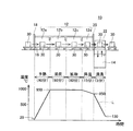
第1実施例の耐熱ケースを説明する前に、まず、焼入れ装置と焼入れ工程を説明する。図1に、焼入れ装置10の模式図を示す。なお、図1の下方に、焼入れ工程におけるワークの温度変化のグラフLを示す。
Before describing the heat-resistant case of the first embodiment, first, a quenching apparatus and a quenching process will be described. In FIG. 1, the schematic diagram of the
焼入れ装置10は主たる部品として、加熱炉12と、エレベータ22と、油槽14を備えている。ワークは、キャリアフレーム30に支持され、コンベア16によって焼入れ装置10内を移動する。キャリアフレーム30は、複数のワークを一度に焼入れするための冶具である。ワークを支持したキャリアフレーム30は、入口扉18を通って加熱炉12へ搬送され、加熱された後に出口扉20を通ってエレベータ22に格納される。その後、ワークを支持したキャリアフレーム30は、エレベータ22によって油槽14へ浸漬されて冷却される。油槽14には、浸漬液(冷却液)として常温〜130℃の油が満たされている。
The
加熱炉12は、4つの小部屋12a、12b、12c、及び12dに区画されている。ワークは、第1小部屋12a内で、約60分かけて常温(約20℃)から約950℃へ昇温される。この工程は予熱工程と呼ばれる。次にワークは第2小部屋12bに搬送される。第2小部屋12b内は炭素を含むガスで満たされている。第2小部屋12b内は約950℃に保たれており、この中で約60分かけてワーク表層に炭素が注入される。この工程は浸炭工程と呼ばれる。次にワークは第3小部屋12cに運ばれる。第3小部屋12cも約950℃に保たれている。この中で、注入された炭素を、約60分をかけてワーク内に拡散させる。この工程は拡散工程と呼ばれる。次にワークは第4小部屋12dに搬送される。第3小部屋では、ワークの温度が約15分をかけて約850℃まで下げられる。この工程は降温工程と呼ばれる。予熱工程から降温工程までは加熱工程と総称される。最後にワークは油槽14へ浸漬されて約130℃に急激に冷却される。浸漬される時間は約5分である。こうしてワークは焼入れされる。加熱工程と浸漬工程を合わせて焼入れ工程と呼ばれる。なお、厳密には焼入れ工程では、予熱工程の前に脱脂工程が実施されるが、本実施例では説明を省略する。
The
各工程の温度や所要時間は、ワークの材質や浸炭深さに依存して調整される。また、焼入れ工程におけるワーク温度は実際には曲線的に変化するが、図1のグラフLはワークの温度変化を模式的に表していることに留意されたい。図1において、焼入れ装置10とグラフをつなぐ破線は、各工程と温度変化の対応を模式的に表している。
The temperature and time required for each process are adjusted depending on the material of the workpiece and the carburization depth. It should be noted that the workpiece temperature in the quenching process actually changes in a curved line, but the graph L in FIG. 1 schematically shows the temperature change of the workpiece. In FIG. 1, a broken line connecting the quenching
上記のとおり、ワークは焼入れ装置内で急激な温度変化に曝される。温度や所要時間が適正でないとワークに大きな歪みが生じたり、望ましい硬さが得られなかったりする。そこで、浸漬工程(冷却工程)を含む各工程におけるワークの物理量を計測する必要がある。ここで「物理量」は、代表的にはワークの表面温度や歪み量である。そのため、キャリアフレーム30にワークとともに計測デバイスを収納して焼入れ装置10内に搬送し、焼入れの全工程に亘ってワークの物理量を計測する。計測デバイスは、ワークに貼着する熱電対や歪みゲージなどのプローブと、プローブから得られる電気信号を処理する計測デバイス本体からなる。計測デバイス本体は、プローブから得られる電気信号を記録するデータロガーや、或いは、プローブから得られる電気信号を焼入れ装置外部のデータロガーへ無線送信する無線機である。熱電対や歪みゲージなどのプローブは焼入れ工程における厳しい温度環境に耐え得るものが存在するが、データロガーや無線機などの計測デバイス本体(電子デバイス)の耐熱温度は、概ね150℃以下である。そのため、焼入れ工程の温度環境から計測デバイス本体を保護する耐熱ケースが必要となる。
As described above, the workpiece is exposed to a rapid temperature change in the quenching apparatus. If the temperature and required time are not appropriate, the workpiece may be greatly distorted or the desired hardness may not be obtained. Therefore, it is necessary to measure the physical quantity of the workpiece in each process including the dipping process (cooling process). Here, the “physical quantity” is typically the surface temperature or strain amount of the workpiece. Therefore, the measuring device is housed in the
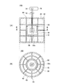
図2に、実施例の耐熱ケース100の模式図を示す。耐熱ケース100は、円筒形の外形状を有している。図2(A)は、耐熱ケース100の模式的縦断面図を示しており、図2(B)は、耐熱ケース100の模式的水平断面図を示している。図2(B)は、図2(A)のB−B線に沿った断面を示している。
In FIG. 2, the schematic diagram of the heat-
耐熱ケース100は、防水断熱ケース32と、外ケース40から構成されている。防水断熱ケース32内には断熱材34が詰込まれている。断熱材34の内側に内部空間32aが形成されており、その内部空間32aに計測デバイス本体50が収容される。符号36は、防水断熱ケース32の蓋と容器の間に配置されたシール材である。シール材36によって、防水断熱ケース32の水密性が保たれる。防水断熱ケース32の内部空間32aからは、デバイス本体50と熱電対或いは歪みゲージなどのプローブ54をつなぐケーブル52が延出している。なお、ケーブル52の回りもシール材で封止されている。
The heat
外ケース40内に、防水断熱ケース32を囲むように断熱材42が詰込まれている。外ケース40は、防水断熱ケース32の周囲に断熱材42を保持している。
A
外ケース40と断熱材42には、浸漬工程において油(浸漬液)をその厚み方向に導くための液体導入路44が設けられている。図2に示されているように、液体導入路44は、外ケース40から防水断熱ケース32の表面まで延びている。また、図2に示されてように、液体導入路44は、防水断熱ケース32の周囲に略等間隔に設けられている。
The
焼入れ装置での焼入れ工程中のワークの温度と歪みの経時変化を測定するときは、プローブ54をワークWに貼着し、計測デバイス本体50を耐熱ケース100に収納し、ワークWととともに耐熱ケース100をキャリアフレーム30に搭載して焼入れ装置10へ入れる。焼入れ装置10内で、耐熱ケース100は加熱工程で約950℃まで加熱された後に油槽14に浸されて約130℃まで冷却される。デバイス本体50は防水性の耐熱ケース100に保護されているので破壊温度(約150℃)には至らない。なお、防水断熱ケース32は、シール材36によって水密性が保たれているので浸漬液が内部空間32a内へ浸入することはない。本実施例の計測デバイス本体50は、プローブ54から得られる電気信号を記録するデータロガーである。計測デバイス本体50は、焼入れ工程終了後に耐熱ケース100から取り出され、記録した計測データがコンピュータへ移される。
When measuring the temporal change of the temperature and strain of the workpiece during the quenching process in the quenching apparatus, the
液体導入路44の効果を説明する。耐熱ケース100は、加熱工程では気体中で加熱され、冷却工程では液体(油)で冷却される。加熱工程では、液体導入路44に高温ガスが流入するので、液体導入路44を設けない場合に比べて耐熱ケースの断熱効果は低下する。他方、加熱工程において、断熱材42は熱を蓄積する。特に高温ガスに曝されている断熱材42の表層に熱が蓄積する。蓄積された熱は徐々に内部へ拡散し、防水断熱ケース32の温度を上昇させる原因となる。加熱工程の後に耐熱ケース100が液体(油)の中に浸漬されると、液体導入路44によって内部に導かれた油が断熱材42を冷却する。このことによって、断熱材42が蓄積した熱による防水断熱ケース32の温度上昇が抑制される。ここで、一般に気体よりも液体の方が熱拡散率が高いので、加熱工程において液体導入路44に侵入した高温ガスが断熱材42に与える単位時間当たりの熱量よりも、浸漬工程において液体導入路44に浸入した浸漬液が断熱材42から奪う単位時間当たりの熱量の方が大きい。従って、液体導入路44によって、計測デバイス本体50を収容する内部空間32aの長時間の断熱性が向上する。特に、液体導入路44は、防水断熱ケース32を囲んでいる断熱材42に等間隔に設けられているので、液体導入路44に導かれる浸漬液が断熱材42の全体を均等に冷却する。
The effect of the
上記のとおり、液体導入路44を備えた耐熱ケース100は、ワークをガス中で加熱した後に液体中で冷却する焼入れ装置に特有の環境変化を利用し、計測デバイス本体を長時間に亘って熱環境から保護することができる。
As described above, the heat-
上記の耐熱ケース100をさらに改良した耐熱ケースを説明する。図3は、第2実施例の耐熱ケース200の部分断面図である。図3は、液体導入路44の入口付近を拡大した断面図である。耐熱ケース200は、液体導入路44の入口にリリーフバルブ65を備えている。リリーフバルブ65を備えること以外は、耐熱ケース200は第1実施例の耐熱ケース100と同じ構造を有している。なお、液体導入路44の全ての入口にリリーフバルブ65が設けられている。
A heat-resistant case obtained by further improving the heat-
ここではリリーフバルブ65についてのみ説明する。リリーフバルブ65は、ボール62とスプリング64、及び、外ケース40に形成されたテーパホール60で構成される。テーパホール60は、液体導入路44の入口に相当する。テーパホール60は、外ケース40の内側から外側に向かって先細りになっている。このテーパホール60にボール62が配置されている。ボール62の背後にスプリング64が配置されており、そのスプリング64がボール62を外側に向かって付勢している。ボール62の直径はテーパホール60の直径よりも大きく、スプリング64の付勢力によってボール62はテーパホール60を塞ぐ。外側から閾値以上の圧力が加わるとボール62が内側に後退してリリーフバルブ65が開く。スプリング64の付勢力は、加熱炉内のガス圧(雰囲気圧)ではリリーフバルブ65が開かず、浸漬工程における外側からの液圧で開く大きさに調整されている。すなわちこのリリーフバルブ65は、加熱炉における雰囲気圧では開かず、浸漬工程における外側からの液圧で開通する気体遮蔽蓋を構成する。リリーフバルブ65は、加熱工程において高温ガスが液体導入路44へ侵入することを阻止し、浸漬工程において浸漬液が浸入することを許容する。リリーフバルブ65により、耐熱ケース200の断熱性能が向上する。
Here, only the
耐熱ケース100の別の改良タイプを説明する。図4は、第3実施例の耐熱ケース300の部分断面図である。図4は、液体導入路44の入口付近を拡大した断面図である。耐熱ケース300は、液体導入路44の入口に気体遮蔽蓋70を備えている。気体遮蔽板70を備えること以外は第1実施例の耐熱ケース100と同じ構造を有している。なお、液体導入路44の全ての入口に気体遮蔽蓋70が設けられている。
Another improved type of heat
気体遮蔽蓋70は、耐熱塗料を固めて形成した板である。その板厚は、浸漬時の液圧によって破壊されるように調整されている。すなわちこの気体遮蔽蓋70は、加熱炉におけるガス圧では開かず、浸漬時の液圧で開通する。気体遮蔽蓋70は、加熱工程において高温ガスが液体導入路44へ侵入することを阻止し、浸漬工程において浸漬液が浸入することを許容する。気体遮蔽蓋70により、耐熱ケース300の断熱性能が向上する。なお、気体遮蔽蓋70は、浸漬液(冷却液)で融解する材料で形成されていてもよい。
The
以上、本発明の具体例を詳細に説明したが、これらは例示に過ぎず、特許請求の範囲を限定するものではない。特許請求の範囲に記載の技術には、以上に例示した具体例を様々に変形、変更したものが含まれる。
本明細書または図面に説明した技術要素は、単独であるいは各種の組合せによって技術的有用性を発揮するものであり、出願時請求項記載の組合せに限定されるものではない。また、本明細書または図面に例示した技術は複数目的を同時に達成し得るものであり、そのうちの一つの目的を達成すること自体で技術的有用性を持つものである。
Specific examples of the present invention have been described in detail above, but these are merely examples and do not limit the scope of the claims. The technology described in the claims includes various modifications and changes of the specific examples illustrated above.
The technical elements described in this specification or the drawings exhibit technical usefulness alone or in various combinations, and are not limited to the combinations described in the claims at the time of filing. In addition, the technology exemplified in this specification or the drawings can achieve a plurality of objects at the same time, and has technical usefulness by achieving one of the objects.
10:焼入れ装置
12:加熱炉
14:油槽
16:コンベア
22:エレベータ
30:キャリアフレーム
32:防水断熱ケース
34、42:断熱材
36:シール材
40:外ケース
44:液体導入路
50:計測デバイス本体
60:テーパホール
62:ボール
64:スプリング
65:リリーフバルブ
70:気体遮蔽蓋
100、200、300:耐熱ケース
10: Quenching device
12: Heating furnace 14: Oil tank 16: Conveyor 22: Elevator 30: Carrier frame 32: Waterproof
Claims (3)
計測デバイス本体を収納するための防水断熱ケースと、
防水断熱ケースを囲んでいる断熱材と、
を備えており、
前記断熱材に、耐熱ケースを浸漬したときに浸漬液を前記断熱材の厚み方向の内側に導く液体導入路が設けられていることを特徴とする耐熱ケース。 It is a heat-resistant case for measuring devices that measures the physical state during the quenching process of workpieces immersed after heating in a quenching device,
A waterproof insulation case to store the measuring device body,
Thermal insulation surrounding the waterproof thermal insulation case;
With
A heat-resistant case characterized in that a liquid introduction path is provided for guiding the immersion liquid to the inside in the thickness direction of the heat-insulating material when the heat-resistant material is immersed in the heat-insulating material.
Priority Applications (1)
| Application Number | Priority Date | Filing Date | Title |
|---|---|---|---|
| JP2009058585A JP5110010B2 (en) | 2009-03-11 | 2009-03-11 | Heat-resistant case |
Applications Claiming Priority (1)
| Application Number | Priority Date | Filing Date | Title |
|---|---|---|---|
| JP2009058585A JP5110010B2 (en) | 2009-03-11 | 2009-03-11 | Heat-resistant case |
Publications (2)
| Publication Number | Publication Date |
|---|---|
| JP2010210516A JP2010210516A (en) | 2010-09-24 |
| JP5110010B2 true JP5110010B2 (en) | 2012-12-26 |
Family
ID=42970839
Family Applications (1)
| Application Number | Title | Priority Date | Filing Date |
|---|---|---|---|
| JP2009058585A Expired - Fee Related JP5110010B2 (en) | 2009-03-11 | 2009-03-11 | Heat-resistant case |
Country Status (1)
| Country | Link |
|---|---|
| JP (1) | JP5110010B2 (en) |
Families Citing this family (2)
| Publication number | Priority date | Publication date | Assignee | Title |
|---|---|---|---|---|
| JP5533597B2 (en) * | 2010-11-25 | 2014-06-25 | トヨタ自動車株式会社 | Temperature measuring device |
| GB201509136D0 (en) * | 2015-05-28 | 2015-07-15 | Phoenixtm Ltd | Thermal protection system |
Family Cites Families (3)
| Publication number | Priority date | Publication date | Assignee | Title |
|---|---|---|---|---|
| US5601363A (en) * | 1994-06-09 | 1997-02-11 | Caterpillar Inc. | Quench system cooling effectiveness meter and method of operating same |
| JP4582558B2 (en) * | 2000-04-14 | 2010-11-17 | 新日鉄エンジニアリング株式会社 | Refractory cooling device layout structure on the bottom wall of the blast furnace furnace |
| JP2008292421A (en) * | 2007-05-28 | 2008-12-04 | Toyota Motor Corp | Data recording apparatus and method of handling the same |
-
2009
- 2009-03-11 JP JP2009058585A patent/JP5110010B2/en not_active Expired - Fee Related
Also Published As
| Publication number | Publication date |
|---|---|
| JP2010210516A (en) | 2010-09-24 |
Similar Documents
| Publication | Publication Date | Title |
|---|---|---|
| RU2548551C2 (en) | Method and device for hardening of steel parts and steel parts thus hardened | |
| JP5533597B2 (en) | Temperature measuring device | |
| US20110023942A1 (en) | Photovoltaic module having improved corrosion resistance and method of producing same | |
| US5261976A (en) | Control system for a soft vacuum furnace | |
| Aramide et al. | Effects of carburization time and temperature on the mechanical properties of carburized mild steel, using activated carbon as carburizer | |
| JP5110010B2 (en) | Heat-resistant case | |
| US2839594A (en) | Contact thermocouple assembly | |
| Rana et al. | Influence of robust drain openings and insulation standoffs on corrosion under insulation behavior of carbon steel | |
| Charpentier et al. | Chemical degradation of SiC/SiC composite for the cladding of gas-cooled fast reactor in case of severe accident scenarios | |
| BR112015000733B1 (en) | process of measuring the surface level of liquid metal and the level of slag surface in the crucible of a metallurgical vat furnace, the outer wall of the crucible of a metallurgical vat furnace and blast furnace | |
| JP4458079B2 (en) | Vacuum carburizing equipment | |
| JP5865614B2 (en) | Water level detector for nuclear power plant | |
| Yevtushenko et al. | Corrosion behaviour of Cr13 steel in CO2 saturated brine with high chloride concentration | |
| JP2009052838A (en) | Vacuum carburizing furnace | |
| KR20100037778A (en) | A pressure control apparatus for a charging room of gas carburization furnace | |
| TW201250195A (en) | Heat treatment apparatus and temperature measuring method thereof | |
| JP6343021B2 (en) | Liquid metal cooled nuclear reactor, system for monitoring oxygen thermodynamic activity in such a reactor, and method for monitoring oxygen thermodynamic activity | |
| JP2008292421A (en) | Data recording apparatus and method of handling the same | |
| JP6274911B2 (en) | Temperature measuring device | |
| CN107884097B (en) | Short thermocouple calibration system | |
| AU2012285581B2 (en) | Method for cooling metal parts having undergone a nitriding/nitrocarburising treatment in a molten salt bath, unit for implementing said method and the treated metal parts | |
| Elzanaty | The effect of carburization on hardness and wear properties of the mild steel samples | |
| US3791209A (en) | High temperature recording lance | |
| KR102397796B1 (en) | Stationary Hot Coil Thermal Insulation Heat Treatment Equipment | |
| Senior et al. | The use of hydrogen in monitoring the anoxic corrosion of copper |
Legal Events
| Date | Code | Title | Description |
|---|---|---|---|
| A621 | Written request for application examination |
Free format text: JAPANESE INTERMEDIATE CODE: A621 Effective date: 20110914 |
|
| A977 | Report on retrieval |
Free format text: JAPANESE INTERMEDIATE CODE: A971007 Effective date: 20120830 |
|
| TRDD | Decision of grant or rejection written | ||
| A01 | Written decision to grant a patent or to grant a registration (utility model) |
Free format text: JAPANESE INTERMEDIATE CODE: A01 Effective date: 20120911 |
|
| A01 | Written decision to grant a patent or to grant a registration (utility model) |
Free format text: JAPANESE INTERMEDIATE CODE: A01 |
|
| A61 | First payment of annual fees (during grant procedure) |
Free format text: JAPANESE INTERMEDIATE CODE: A61 Effective date: 20120924 |
|
| FPAY | Renewal fee payment (event date is renewal date of database) |
Free format text: PAYMENT UNTIL: 20151019 Year of fee payment: 3 |
|
| R151 | Written notification of patent or utility model registration |
Ref document number: 5110010 Country of ref document: JP Free format text: JAPANESE INTERMEDIATE CODE: R151 |
|
| FPAY | Renewal fee payment (event date is renewal date of database) |
Free format text: PAYMENT UNTIL: 20151019 Year of fee payment: 3 |
|
| LAPS | Cancellation because of no payment of annual fees |