JP5110001B2 - Wireless communication system and wireless communication method - Google Patents
Wireless communication system and wireless communication method Download PDFInfo
- Publication number
- JP5110001B2 JP5110001B2 JP2009024639A JP2009024639A JP5110001B2 JP 5110001 B2 JP5110001 B2 JP 5110001B2 JP 2009024639 A JP2009024639 A JP 2009024639A JP 2009024639 A JP2009024639 A JP 2009024639A JP 5110001 B2 JP5110001 B2 JP 5110001B2
- Authority
- JP
- Japan
- Prior art keywords
- channel
- wireless communication
- information indicating
- control unit
- channel numbers
- Prior art date
- Legal status (The legal status is an assumption and is not a legal conclusion. Google has not performed a legal analysis and makes no representation as to the accuracy of the status listed.)
- Expired - Fee Related
Links
Images


Landscapes
- Mobile Radio Communication Systems (AREA)
Description
本発明は、無線通信システム及び無線通信方法に関する。 The present invention relates to a wireless communication system and a wireless communication method.
無線通信により用いられる周波数帯として、例えば通信規格「IEEE802.15.4」の場合、2.4[GHz]帯がその一つとして挙げられる。「IEEE802.15.4」では無線通信は、2.4[GHz]帯を11[ch]〜26[ch]の全16チャンネルに分割した何れか一のチャンネルにより行われる。
一般に、何れのチャンネルを使用するかについてはコーディネータによってスキャンされる各チャンネルの電界強度に基づいて決定される。
As a frequency band used for wireless communication, for example, in the case of the communication standard “IEEE802.15.4”, the 2.4 [GHz] band is one of them. In “IEEE802.15.4”, wireless communication is performed by any one channel obtained by dividing the 2.4 [GHz] band into a total of 16 channels of 11 [ch] to 26 [ch].
Generally, which channel is used is determined based on the electric field strength of each channel scanned by the coordinator.
コーディネータとはネットワークの立ち上げを行うノードをいい、ノードとはネットワークを構成する一つ一つの要素をいう。また、コーディネータからのビーコン受信やコーディネータとの無線通信を行うノードをここではネットワークデバイスというものとする。 A coordinator refers to a node that starts up a network, and a node refers to each element constituting the network. A node that performs beacon reception from the coordinator and wireless communication with the coordinator is referred to as a network device here.
コーディネータによりスキャンされた各チャンネルの電界強度のうち、電界強度の最も小さいチャンネルがコーディネータとネットワークデバイスとの間の無線通信で使用するチャンネル(以下、「使用チャンネル」)として決定される。 Of the electric field intensities of the channels scanned by the coordinator, the channel with the smallest electric field intensity is determined as a channel (hereinafter “used channel”) used in wireless communication between the coordinator and the network device.
電界強度の最も小さいチャンネルは、電波干渉が最も小さく、通信環境が最適なチャンネルである。電界強度の最も小さいチャンネルを使用チャンネルとすることで、スループットの低下や接続の途切れを回避し得る。 The channel with the lowest electric field intensity is the channel with the smallest radio wave interference and the optimum communication environment. By using the channel with the lowest electric field strength as the channel to be used, it is possible to avoid a decrease in throughput and disconnection of connection.
ここで、コーディネータによるスキャンだけに基づいて使用チャンネルが決定される場合、決定された使用チャンネルが全てのネットワークデバイスにとって必ずしも最適とはいえない場合がある。 Here, when the used channel is determined based only on the scan by the coordinator, the determined used channel may not be optimal for all network devices.
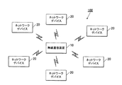
図12に、スター型のネットワーク1を示す。
ネットワーク1では、1つのコーディネータ2に対し複数のネットワークデバイス3〜8が無線通信を行う。
FIG. 12 shows a
In the
コーディネータ2は、電波干渉発生源9の影響範囲91に含まれないため、電波干渉発生源9と電波干渉するチャンネルを使用チャンネルとして決定する場合がある。この場合、ネットワークデバイス3、4は影響範囲91に含まれるため、決定された使用チャンネルで無線通信を行うと電波干渉が生じ、スループットが低下する等の問題が生じる。
Since the
特許文献1によれば、スター型のネットワークにおいて、複数のネットワークデバイスが電界強度スキャンを行い、ネットワークデバイスによるスキャン結果に基づいて最適な使用チャンネルを決定する技術が開示されている。
According to
しかし、特許文献1の技術では、ネットワークデバイスの数が増加するほど、ネットワーク全体でトラフィックが増加し、コーディネータの処理負担も増加する問題が生じる。
However, with the technique of
本発明の課題は、トラフィックの増加を抑えつつ、各ネットワークデバイスにとって最適な使用チャンネルを決定し得る無線通信システムを提供することである。 An object of the present invention is to provide a wireless communication system capable of determining an optimum channel to be used for each network device while suppressing an increase in traffic.
請求項1に記載の発明によれば、
第1無線通信装置と一又は複数の第2無線通信装置との間で無線通信を行う無線通信システムにおいて、
前記第1無線通信装置は、
電界強度スキャンの結果に基づいて、電界強度に応じたチャンネル番号の配列を示す情報を生成する第1の制御部と、前記第1の制御部により生成されたチャンネル番号の配列を示す情報を送信し、及び前記第2無線通信装置により生成されたチャンネル番号の配列を示す情報を受信する第1の無線部と、前記第1の制御部により生成されたチャンネル番号の配列を示す情報及び前記第2無線通信装置により生成されたチャンネル番号の配列を示す情報を記憶する第1の記憶部と、を備え、前記第1の制御部は、前記記憶されているチャンネル番号の配列を示す情報に基づいて、当該配列されているチャンネル番号のうち電界強度が小さい一のチャンネル番号を選択し、当該選択されたチャンネル番号に対応するチャンネルを前記第2無線通信装置との無線通信に使用するチャンネルとして決定し、
前記第2無線通信装置は、
電界強度スキャンの結果に基づいて、電界強度に応じたチャンネル番号の配列を示す情報を生成する第2の制御部と、前記第2の制御部により生成されたチャンネル番号の配列を示す情報を送信し、及び前記第1無線通信装置により生成されたチャンネル番号の配列を示す情報を受信する第2の無線部と、前記第2の制御部により生成されたチャンネル番号の配列を示す情報及び前記第1無線通信装置により生成されたチャンネル番号の配列を示す情報を記憶する第2の記憶部と、を備え、前記第2の制御部は、前記記憶されているチャンネル番号の配列を示す情報同士を比較して配列が異なる場合にのみ、前記第2の制御部により生成されたチャンネル番号の配列を示す情報を前記第1無線通信装置に送信することを決定する無線通信システムが提供される。
According to the invention of
In a wireless communication system that performs wireless communication between a first wireless communication device and one or more second wireless communication devices,
The first wireless communication device is:
Based on the result of the electric field strength scan, a first control unit that generates information indicating an array of channel numbers corresponding to the electric field strength, and information indicating an array of channel numbers generated by the first control unit are transmitted. and, and the a first radio unit by the second receiving information indicative of a sequence of channel number generated by the wireless communication device, the first control unit information and indicating the sequence of the generated channel numbers by the first A first storage unit storing information indicating an array of channel numbers generated by the two wireless communication devices, wherein the first control unit is based on the information indicating the stored array of channel numbers Then, one channel number having a low electric field strength is selected from the arranged channel numbers, and a channel corresponding to the selected channel number is selected as the second wireless communication channel. Determined as a channel to be used for wireless communication with the device,
The second wireless communication device is
Based on the result of the electric field strength scan, a second control unit that generates information indicating an array of channel numbers corresponding to the electric field strength, and information indicating the array of channel numbers generated by the second control unit are transmitted. and, and the second radio unit for receiving information indicating the sequence of the generated channel numbers by the first radio communication apparatus, the second control unit information and indicating the sequence of the generated channel numbers by the first A second storage unit that stores information indicating an array of channel numbers generated by one wireless communication device, wherein the second control unit stores information indicating the stored array of channel numbers. Only when the arrangement is different as compared, a wireless communication system that determines to transmit information indicating the arrangement of the channel numbers generated by the second control unit to the first wireless communication apparatus Beam is provided.
また、請求項5に記載の発明によれば、
第1無線通信装置と一又は複数の第2無線通信装置との間で無線通信を行う無線通信方法において、
前記第1無線通信装置による工程は、
第1の制御部により、電界強度スキャンの結果に基づいて、電界強度に応じたチャンネル番号の配列を示す情報を生成する工程と、第1の無線部により、前記第1の制御部により生成されたチャンネル番号の配列を示す情報を送信し、及び前記第2無線通信装置により生成されたチャンネル番号の配列を示す情報を受信する工程と、第1の記憶部により、前記第1の制御部により生成されたチャンネル番号の配列を示す情報及び前記第1の無線部により受信されたチャンネル番号の配列を示す情報を記憶する工程と、を含み、前記第1の制御部による工程は、前記記憶されているチャンネル番号の配列を示す情報に基づいて、当該配列されているチャンネル番号のうち電界強度が小さい一のチャンネル番号を選択し、当該選択されたチャンネル番号に対応するチャンネルを前記第2無線通信装置との無線通信に使用するチャンネルとして決定する工程を含み、
前記第2無線通信装置による工程は、
第2の制御部により、電界強度スキャンの結果に基づいて、電界強度に応じたチャンネル番号の配列を示す情報を生成する工程と、第2の無線部により、前記第2の制御部により生成されたチャンネル番号の配列を示す情報を送信し、及び前記第1無線通信装置により生成されたチャンネル番号の配列を示す情報を受信する工程と、第2の記憶部により、前記第2の制御部により生成されたチャンネル番号の配列を示す情報及び前記第2の無線部により受信されたチャンネル番号の配列を示す情報を記憶する工程と、を含み、前記第2の制御部による工程は、前記記憶されているチャンネル番号の配列を示す情報同士を比較して配列が異なる場合にのみ、前記第2の制御部により生成されたチャンネル番号の配列を示す情報を前記第1無線通信装置に送信することを決定する工程を含む無線通信方法が提供される。
According to the invention as set forth in
In a wireless communication method for performing wireless communication between a first wireless communication device and one or more second wireless communication devices,
The process by the first wireless communication device includes:
Generated by the first control unit by the first control unit by the first control unit by generating information indicating an array of channel numbers according to the electric field strength based on the result of the electric field strength scan. It transmits information indicating the sequence of channel number, and a step of receiving information indicating the sequence of the generated channel numbers by the second wireless communication device, the first storage section, by the first control unit Storing the generated information indicating the arrangement of channel numbers and the information indicating the arrangement of channel numbers received by the first radio unit, the step by the first control unit being stored Based on the information indicating the arrangement of the channel numbers being selected, one channel number having a low electric field strength is selected from the arranged channel numbers, and the selected channel number is selected. Wherein the step of determining the channel corresponding to the number as a channel to be used for wireless communication with the second wireless communication device,
The process by the second wireless communication device includes:
The second control unit generates information indicating the arrangement of channel numbers according to the electric field strength based on the result of the electric field intensity scan, and the second radio unit generates the information by the second control unit. transmits information indicating the sequence of channel number, and a step of receiving information indicating the sequence of the generated channel numbers by the first radio communication device, the second storage unit, by the second control unit Storing information indicating the generated channel number arrangement and information indicating the channel number arrangement received by the second radio unit, and the step by the second control unit is stored as The information indicating the channel number arrangement generated by the second control unit is only displayed when the information indicating the arrangement of the channel numbers is compared and the arrangement is different. A wireless communication method comprising the step of determining to transmit device is provided.
本発明によれば、第2無線通信装置は、使用チャンネルの決定又は変更が必要な場合に、電界強度スキャンの結果を第1無線通信装置に送信するためトラフィックの不要な増加を防止することができる。また、第1無線通信装置は、複数の第2無線通信装置から取得した電界強度スキャンの結果に基づいて使用チャンネルを決定するため、各第2無線通信装置にとって最適な使用チャンネルを決定することができる。 According to the present invention, the second wireless communication device transmits an electric field intensity scan result to the first wireless communication device when it is necessary to determine or change the channel to be used, thereby preventing an unnecessary increase in traffic. it can. In addition, since the first wireless communication device determines the use channel based on the result of the electric field intensity scan acquired from the plurality of second wireless communication devices, it is possible to determine the optimum use channel for each second wireless communication device. it can.
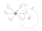
図1に、本実施形態における無線通信システム100を示す。
無線通信システム100は、第1無線通信装置(コーディネータ)10と、一又は複数の第2無線通信装置(ネットワークデバイス)20とを備えて構成される。
FIG. 1 shows a
The
無線通信システム100は、コーディネータ10とネットワークデバイス20との間で例えば、通信規格「IEEE802.15」を用いた無線PAN(Personal Area Network)を構築する。無線PANでは、2.4[GHz]帯の周波数帯域を11[ch]〜26[ch]の全16チャンネルに分割し、何れか一のチャンネルを使用チャンネルとして用いる。
本実施形態では、通信規格「IEEE802.15」を用いることとしたが、これに限らず通信規格「IEEE802.11」等を用いても同様の作用効果を有する。
The
In this embodiment, the communication standard “IEEE802.15” is used. However, the present invention is not limited to this, and the same effect can be obtained by using the communication standard “IEEE802.11” or the like.
図2に、本実施形態におけるコーディネータ10の内部構成を示す。
コーディネータ10は、制御部11、記憶部12、無線部13、アンテナANT1、操作表示部14等を備えて構成される。また、各部はバスBSで接続されている。
FIG. 2 shows an internal configuration of the
The
制御部11は、CPU、RAM、ROM等により構成され、記憶部12との協働によりコーディネータ10の各部を集中制御する。
The
記憶部12は、HDD(Hard Disk Drive)等の不揮発性メモリにより構成され、各種プログラム及び各種データを記憶する。各種データには、例えば電界強度スキャンの結果が含まれる。
The
無線部13は、IEEE802.15.4による無線PAN通信を行う。
図3に、無線部13の内部構成を示す。
無線部13は、送信するデータの位相を変調するGFSK変調部131、周波数を変調する拡散変調部132を備える。
また、無線部13は、受信したデータの周波数を逆拡散する逆拡散部133、位相を逆変調するGFSK逆変調部134を備える。
The
FIG. 3 shows an internal configuration of the
The
The
また、無線部13は、全16チャンネル分の電界強度をスキャンし、スキャンによって得られた結果を記憶部12に出力する。
In addition, the
操作表示部14は、LCD(Liquid Crystal Display)又はEL(Electroluminescent)ディスプレイ等とタッチパネルとを備えて構成される。
LCD又はELディスプレイは、制御部11による制御に従い表示処理を行う。
タッチパネルは、外部からの接触により検出した座標を制御部11に出力する。なお、操作部分にハードキーを備え、表示部分と操作部分とを分離させた構成としてもよい。
The
The LCD or EL display performs display processing according to control by the
The touch panel outputs coordinates detected by external contact to the
図4に、本実施形態におけるネットワークデバイス20の内部構成を示す。
ネットワークデバイス20は、制御部21、記憶部22、無線部23、アンテナANT2、操作表示部24等を備えて構成される。また、各部はバスBSで接続されている。
ネットワークデバイス20の基本的構成及び各部の構成は、コーディネータ10と同様であるためここでの説明は省略する。
FIG. 4 shows an internal configuration of the
The
Since the basic configuration of the
図5を参照して、無線通信システム100における使用チャンネル決定処理について説明する。
コーディネータ10は、無線部13により、11[ch]〜26[ch]の全16チャンネル分について電界強度スキャンを行う(ステップS1)。
With reference to FIG. 5, the used channel determination process in the radio |
The
コーディネータ10は、制御部11により、電界強度スキャンにより得られたスキャン結果に基づいてチャンネル番号の配列を示す情報(以下、単に「チャンネル番号の配列」という)を生成する処理を行う(ステップS2)。
The
図7を参照して、チャンネル番号の配列生成処理について説明する。
制御部11は、チャンネル番号順(11[ch]〜26[ch])の配列を電界強度の小さいチャンネルから大きいチャンネルへと並び替える(ステップS2a)。
つまり、制御部11は電波干渉が少ないチャンネル順にチャンネル番号を並び替える。
With reference to FIG. 7, the channel number array generation processing will be described.
The
That is, the
制御部11は、予め定められた閾値以上の電界強度であるチャンネルのチャンネル番号を「0」とする(ステップS2b)。
なお、ステップS2bの処理はデータサイズの削減を目的とするものであることから、本発明の効果を達成するために常に必要な処理というわけではない。
The
In addition, since the process of step S2b aims at reduction of data size, it is not always a process required in order to achieve the effect of this invention.
制御部11は、ステップS2bで「0」としなかったチャンネル番号から「11」を減算する(ステップS2c)。
11を減算することにより、配列要素の値を0〜15とすることができ、ビット数を減らすことができる。
The
By subtracting 11, the value of the array element can be 0 to 15, and the number of bits can be reduced.
制御部11は、ステップS2cを経た後のチャンネル番号の配列を記憶部12に記憶して(ステップS2d)、チャンネル番号の配列生成処理を終了する。
The
図8に、チャンネル番号の配列の概念図を示す。
図8に示すチャンネル番号の配列R1〜R4は、図7の処理で生成される配列である。
配列R1は、11[ch]〜26[ch]の各チャンネル番号及びチャンネル番号に対応するスキャン結果の配列である。
配列R2は、スキャン結果に基づいて、電界強度の小さいチャンネルから大きいチャンネルへとチャンネル番号が並び替えられた配列である。
FIG. 8 shows a conceptual diagram of the arrangement of channel numbers.
Channel number arrays R1 to R4 shown in FIG. 8 are arrays generated by the process of FIG.
The array R1 is an array of scan results corresponding to each channel number and channel number of 11 [ch] to 26 [ch].
The array R2 is an array in which channel numbers are rearranged from a channel with a small electric field strength to a channel with a large electric field based on the scan result.
配列R3は、スキャン結果に基づいて、予め定められた閾値(ここでは50とする)よりも大きいスキャン結果であるチャンネルのチャンネル番号が「0」とされた配列である。
配列R4は、「0」以外のチャンネル番号から「11」を減算した配列である。
最終的に生成される配列R4では、電界強度の小さいチャンネル番号がある程度絞り込まれ、比較的電波環境の良好なチャンネルが順に並べられる。
The array R3 is an array in which the channel number of a channel that is a scan result larger than a predetermined threshold (here, 50) is set to “0” based on the scan result.
The array R4 is an array obtained by subtracting “11” from a channel number other than “0”.
In the finally generated array R4, channel numbers having a small electric field strength are narrowed down to some extent, and channels having a relatively good radio wave environment are arranged in order.
図5に戻り、コーディネータ10は、生成したチャンネル番号の配列R4に基づいて、使用チャンネルを決定する(ステップS3)。
図8の配列R4によれば、ここで決定される使用チャンネルは15[ch](「11」減算後の値は「4」)となる。
Returning to FIG. 5, the
According to the array R4 in FIG. 8, the channel used here is 15 [ch] (the value after “11” subtraction is “4”).
コーディネータ10は、生成したチャンネル番号の配列をビーコンに含ませ(ステップS4)、ビーコンを各ネットワークデバイス20に送信する(ステップS5)。
なお、ビーコンの送信回数は予め定められた回数分行うとしてもよい。この場合、ビーコンの送信周期とネットワークデバイス20がビーコンに含まれたチャンネル番号の配列を受信するために要する時間との関係において、ビーコンの送信周期の方を長くする必要がある。
The
Note that the number of beacons transmitted may be a predetermined number of times. In this case, it is necessary to make the beacon transmission cycle longer in the relationship between the beacon transmission cycle and the time required for the
ここでは、コーディネータ10はビーコンを2つのネットワークデバイス20に1回送信する場合について説明する。また、説明の便宜上、2つのネットワークデバイス20をネットワークデバイスN1、N2と区別して説明する。
Here, a case where the
図9に、ビーコンのフレーム構成を示す。
ビーコンフレームBFは、上述したステップS5で、コーディネータ10が周期的に送信するビーコンフレームである。なお、図9に示すビーコンフレームBFは、IEEE802.15.14の規格書に基づくものである。
FIG. 9 shows a frame structure of the beacon.
The beacon frame BF is a beacon frame periodically transmitted by the
ビーコンペイロードBPには、要素数が16で各要素が4ビットである図8の配列R4と、配列R4の先頭に8ビットを加えた計9バイトのデータが含まれる。配列R4の先頭の8ビットは、配列R4における有効な要素数を示す。つまりここでは、配列R4の先頭の8ビットの値は「5」であるから、配列R4の有効な要素は先頭から5ヶ所(要素「4」、「5」、「3」、「7」、「8」)であることを示す。
なお、ビーコンペイロードBPに配列R4とともに電界強度スキャンの結果(図8:R1参照)も含ませるとしてもよい。
The beacon payload BP includes an array R4 of FIG. 8 in which the number of elements is 16 and each element is 4 bits, and a total of 9 bytes of data including 8 bits added to the head of the array R4. The first 8 bits of the array R4 indicate the number of valid elements in the array R4. That is, here, since the value of the first 8 bits of the array R4 is “5”, there are five valid elements of the array R4 (elements “4”, “5”, “3”, “7”, “8”).
The beacon payload BP may include the result of the electric field intensity scan (see FIG. 8: R1) together with the array R4.
図5に戻り、ネットワークデバイスN1は、無線部23により、ビーコンをサーチする(ステップS6)。 Returning to FIG. 5, the network device N1 searches the beacon by the wireless unit 23 (step S6).
ネットワークデバイスN1は、コーディネータ10から送信されるビーコンを受信した後、ビーコンに含まれるチャンネル番号の配列を抽出して記憶する(ステップS7)。
After receiving the beacon transmitted from the
ネットワークデバイスN1は、無線部23により、11[ch]〜26[ch]の全16チャンネル分について電界強度スキャンを行う(ステップS8)。
The network device N1 uses the
ネットワークデバイスN1は、電界強度スキャンにより得られたスキャン結果に基づいて、チャンネル番号の配列を生成する処理を行う(ステップS9)。
チャンネル番号の配列を生成する処理については、図7、図8に示した処理と同様であるため、ここでの説明は省略する。
The network device N1 performs processing for generating an array of channel numbers based on the scan result obtained by the electric field intensity scan (step S9).
The process for generating the channel number array is the same as the process shown in FIGS. 7 and 8, and will not be described here.
ネットワークデバイスN1は、記憶部22に記憶されている2つのチャンネル番号の配列を比較する(ステップS10)。
2つのチャンネル番号の配列とは、コーディネータ10により生成されたチャンネル番号の配列とネットワークデバイスN1が生成したチャンネル番号の配列である。
The network device N1 compares the two channel number arrays stored in the storage unit 22 (step S10).
The two channel number arrays are an array of channel numbers generated by the
ネットワークデバイスN2もネットワークデバイスN1と同様に、上記処理を行う(ステップS11〜S15)。 Similarly to the network device N1, the network device N2 performs the above processing (steps S11 to S15).
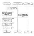
図6に、図5の使用チャンネル決定処理の続きを示す。
ネットワークデバイスN1は、ステップS10で2つのチャンネル番号の配列を比較した結果、異なる場合に限り、チャンネル番号の配列をコーディネータ10に送信する(ステップS16)。
なお、ここで送信するチャンネル番号の配列はネットワークデバイスN1が生成したチャンネル番号の配列である。
FIG. 6 shows the continuation of the used channel determination process of FIG.
The network device N1 transmits the channel number arrangement to the
The channel number array transmitted here is the channel number array generated by the network device N1.
また、2つのチャンネル番号の配列を比較した結果、異ならない場合には、ネットワークデバイスN1は、チャンネル番号の配列をコーディネータ10に送信することなく使用チャンネル決定処理を終了する。
Further, if the result of comparing the two channel number arrays does not differ, the network device N1 ends the used channel determination process without transmitting the channel number array to the
コーディネータ10は、ネットワークデバイスN1からのチャンネル番号の配列を記憶する(ステップS17)。
The
ネットワークデバイスN2は、ネットワークデバイスN1と同様、ステップS15で2つのチャンネル番号の配列を比較した結果、異なる場合にチャンネル番号の配列をコーディネータ10に送信する(ステップS18)。
Similarly to the network device N1, the network device N2 transmits the channel number arrangement to the
コーディネータ10は、ネットワークデバイスN2からのチャンネル番号の配列を記憶する(ステップS19)。
The
コーディネータ10は、ネットワークデバイスN1及びネットワークデバイスN2からのチャンネル番号の配列に基づいて、ステップS3で決定した使用チャンネルとは別の新たな使用チャンネルを決定する(ステップS20)。
The
図10を参照して、新たな使用チャンネルの決定処理について説明する。
制御部11は、コーディネータ10が生成したチャンネル番号の配列とネットワークデバイスN1、N2が生成したチャンネル番号の配列とのAND(論理積)を算出する(ステップS20a)。
With reference to FIG. 10, the process of determining a new used channel will be described.
The
制御部11は、ANDを算出した結果、1以上のチャンネル番号が算出されたか否か判断する(ステップS20b)。
The
1以上のチャンネル番号が算出されない場合(ステップS20b;N)、つまり1つも算出されない場合、制御部11はステップS20dに移行する。
1以上のチャンネル番号が算出された場合(ステップS20b;Y)、制御部11は、2以上のチャンネル番号が算出されたか否か判断する(ステップS20c)。
When one or more channel numbers are not calculated (step S20b; N), that is, when none is calculated, the
When one or more channel numbers are calculated (step S20b; Y), the
2以上のチャンネル番号が算出されない場合(ステップS20c;N)、つまり1つしかチャンネル番号が算出されなかった場合、制御部11はステップS20eに移行する。
2以上のチャンネル番号が算出された場合(ステップS20c;Y)、制御部11は、コーディネータ10によるスキャン結果が最適なチャンネル番号を選択する(ステップS20d)。
「スキャン結果が最適なチャンネル番号」とは、11[ch]〜26[ch]のうち、電界強度が小さいチャンネルの番号をいう。電界強度が小さいチャンネルとして、電界強度が最も小さいチャンネルでもよく、また電界強度が比較的小さいチャンネルでもよい。
When two or more channel numbers are not calculated (step S20c; N), that is, when only one channel number is calculated, the
When two or more channel numbers are calculated (step S20c; Y), the
“The channel number with the optimum scan result” refers to the channel number having a low electric field strength among 11 [ch] to 26 [ch]. The channel with the lowest electric field strength may be the channel with the lowest electric field strength or a channel with a relatively low electric field strength.
制御部11は、選択又は算出したチャンネル番号に「11」を加算して(ステップS20e)、新たな使用チャンネルのチャンネル番号を決定する(ステップS20f)。
The
図11に、新たな使用チャンネルの決定処理(図10)における配列の概念図を示す。
配列R4は、コーディネータ10により生成されたチャンネル番号の配列である(図8参照)。
配列R41は、ネットワークデバイスN1により生成されたチャンネル番号の配列である。
配列R42は、ネットワークデバイスN2により生成されたチャンネル番号の配列である。
FIG. 11 is a conceptual diagram of an arrangement in the process of determining a new used channel (FIG. 10).
The array R4 is an array of channel numbers generated by the coordinator 10 (see FIG. 8).
The array R41 is an array of channel numbers generated by the network device N1.
The array R42 is an array of channel numbers generated by the network device N2.
図11に示す各配列(R4、R41、R42)についてAND(論理積)の演算処理を行うと、「3」と「5」が算出される(ステップS20a参照)。
コーディネータ10により生成されたチャンネル番号の配列において、「5」の方が最適なチャンネルであるため「5」が選択される(ステップS20d参照)。
「5」に「11」が加算され、実際のチャンネル番号「16」が生成される(ステップS20e参照)。
生成されたチャンネル番号が新たな使用チャンネルのチャンネル番号として決定される(ステップS20f参照)。
When AND (logical product) arithmetic processing is performed on each array (R4, R41, R42) shown in FIG. 11, "3" and "5" are calculated (see step S20a).
In the arrangement of channel numbers generated by the
“11” is added to “5” to generate the actual channel number “16” (see step S20e).
The generated channel number is determined as the channel number of the new used channel (see step S20f).
図6に戻り、コーディネータ10は、ステップS3(図5参照)で決定した使用チャンネルのチャンネル番号とステップS20で決定した新たな使用チャンネルのチャンネル番号とが異なる場合、チャンネルを切り替えて(ステップS21)、使用チャンネル決定処理を終了する。
Returning to FIG. 6, when the channel number of the used channel determined in step S3 (see FIG. 5) is different from the channel number of the new used channel determined in step S20, the
以上のように、本実施形態によれば、ネットワークデバイス20は、使用チャンネルの決定又は変更が必要な場合に、電界強度スキャンの結果をコーディネータに送信し、コーディネータ10にチャンネル番号の配列を不要に送信しないため、トラフィックの増加を抑えつつ、各ネットワークデバイス20にとって最適な使用チャンネルを決定することができる。また、コーディネータ10の処理負担も軽減することができる。
As described above, according to the present embodiment, the
また、コーディネータ10は、チャンネル番号の配列をビーコンによって送信することができる。無線通信システム100内に複数のネットワークデバイス20が存在する場合でも、チャンネル番号の配列を定期的に同時配信することができる。
Further, the
また、コーディネータ10及びネットワークデバイス20は、電界強度スキャンの結果に基づいて、電界強度順にチャンネル番号を並び替え、予め定められた閾値(例えば50)以上の電界強度のチャンネルについてチャンネル番号を0とし、予め定められた値(例えば11)を減算することでチャンネル番号の配列を生成することができる。つまり、コーディネータ10とネットワークデバイス20との間で電界強度スキャンの結果を送受信する際、データサイズを減らして送受信することができる。
In addition, the
また、コーディネータ10は、制御部11により生成されたチャンネル番号の配列と制御部21により生成されたチャンネル番号の配列との論理積を算出することで、使用チャンネルを決定することができる。
Further, the
100 無線通信システム
10 第1無線通信装置(コーディネータ)
20 第2無線通信装置(ネットワークデバイス)
11、21 制御部
12、22 記憶部
13、23 無線部
ANT1、2 アンテナ
100
20 Second wireless communication apparatus (network device)
11, 21
Claims (5)
前記第1無線通信装置は、
電界強度スキャンの結果に基づいて、電界強度に応じたチャンネル番号の配列を示す情報を生成する第1の制御部と、前記第1の制御部により生成されたチャンネル番号の配列を示す情報を送信し、及び前記第2無線通信装置により生成されたチャンネル番号の配列を示す情報を受信する第1の無線部と、前記第1の制御部により生成されたチャンネル番号の配列を示す情報及び前記第2無線通信装置により生成されたチャンネル番号の配列を示す情報を記憶する第1の記憶部と、を備え、前記第1の制御部は、前記記憶されているチャンネル番号の配列を示す情報に基づいて、当該配列されているチャンネル番号のうち電界強度が小さい一のチャンネル番号を選択し、当該選択されたチャンネル番号に対応するチャンネルを前記第2無線通信装置との無線通信に使用するチャンネルとして決定し、
前記第2無線通信装置は、
電界強度スキャンの結果に基づいて、電界強度に応じたチャンネル番号の配列を示す情報を生成する第2の制御部と、前記第2の制御部により生成されたチャンネル番号の配列を示す情報を送信し、及び前記第1無線通信装置により生成されたチャンネル番号の配列を示す情報を受信する第2の無線部と、前記第2の制御部により生成されたチャンネル番号の配列を示す情報及び前記第1無線通信装置により生成されたチャンネル番号の配列を示す情報を記憶する第2の記憶部と、を備え、前記第2の制御部は、前記記憶されているチャンネル番号の配列を示す情報同士を比較して配列が異なる場合にのみ、前記第2の制御部により生成されたチャンネル番号の配列を示す情報を前記第1無線通信装置に送信することを決定する無線通信システム。 In a wireless communication system that performs wireless communication between a first wireless communication device and one or more second wireless communication devices,
The first wireless communication device is:
Based on the result of the electric field strength scan, a first control unit that generates information indicating an array of channel numbers corresponding to the electric field strength, and information indicating an array of channel numbers generated by the first control unit are transmitted. and, and the a first radio unit by the second receiving information indicative of a sequence of channel number generated by the wireless communication device, the first control unit information and indicating the sequence of the generated channel numbers by the first A first storage unit storing information indicating an array of channel numbers generated by the two wireless communication devices, wherein the first control unit is based on the information indicating the stored array of channel numbers Then, one channel number having a low electric field strength is selected from the arranged channel numbers, and a channel corresponding to the selected channel number is selected as the second wireless communication channel. Determined as a channel to be used for wireless communication with the device,
The second wireless communication device is
Based on the result of the electric field strength scan, a second control unit that generates information indicating an array of channel numbers corresponding to the electric field strength, and information indicating the array of channel numbers generated by the second control unit are transmitted. and, and the second radio unit for receiving information indicating the sequence of the generated channel numbers by the first radio communication apparatus, the second control unit information and indicating the sequence of the generated channel numbers by the first A second storage unit that stores information indicating an array of channel numbers generated by one wireless communication device, wherein the second control unit stores information indicating the stored array of channel numbers. Only when the arrangement is different as compared, a wireless communication system that determines to transmit information indicating the arrangement of the channel numbers generated by the second control unit to the first wireless communication apparatus Beam.
前記第2の制御部は、前記ビーコンを前記第2の無線部により受信するとともに、当該ビーコンから前記チャンネル番号の配列を示す情報を抽出する請求項1に記載の無線通信システム。 The first control unit includes information indicating the arrangement of the channel numbers in a beacon, transmits the beacon to the second wireless communication device by the first wireless unit,
The wireless communication system according to claim 1, wherein the second control unit receives the beacon by the second wireless unit and extracts information indicating an array of the channel numbers from the beacon.
前記第2の制御部は、前記第2の無線部により前記電界強度スキャンを行い、当該スキャンの結果に基づいて、電界強度順にチャンネル番号の配列を並び替え、予め定められた閾値以上の電界強度のチャンネルについてチャンネル番号を0とし、0以外のチャンネル番号から予め定められた値を減算する処理を施すことにより、前記チャンネル番号の配列を示す情報を生成する請求項1又は2に記載の無線通信システム。 The first control unit performs an electric field intensity scan by the first radio unit, rearranges the arrangement of the channel numbers in the order of the electric field intensity based on the result of the scan, and sets the electric field intensity equal to or higher than a predetermined threshold value. A channel number is set to 0 for a channel, and a process of subtracting a predetermined value from a channel number other than 0 is performed to generate information indicating an array of the channel numbers,
The second control unit performs the electric field intensity scan by the second radio unit, rearranges the arrangement of the channel numbers in the order of the electric field intensity based on the result of the scan, and the electric field intensity equal to or higher than a predetermined threshold value. 3. The wireless communication according to claim 1, wherein a channel number is set to 0 for each channel and information indicating an array of the channel numbers is generated by performing a process of subtracting a predetermined value from a channel number other than 0. 4. system.
前記第1無線通信装置による工程は、
第1の制御部により、電界強度スキャンの結果に基づいて、電界強度に応じたチャンネル番号の配列を示す情報を生成する工程と、第1の無線部により、前記第1の制御部により生成されたチャンネル番号の配列を示す情報を送信し、及び前記第2無線通信装置により生成されたチャンネル番号の配列を示す情報を受信する工程と、第1の記憶部により、前記第1の制御部により生成されたチャンネル番号の配列を示す情報及び前記第1の無線部により受信されたチャンネル番号の配列を示す情報を記憶する工程と、を含み、前記第1の制御部による工程は、前記記憶されているチャンネル番号の配列を示す情報に基づいて、当該配列されているチャンネル番号のうち電界強度が小さい一のチャンネル番号を選択し、当該選択されたチャンネル番号に対応するチャンネルを前記第2無線通信装置との無線通信に使用するチャンネルとして決定する工程を含み、
前記第2無線通信装置による工程は、
第2の制御部により、電界強度スキャンの結果に基づいて、電界強度に応じたチャンネル番号の配列を示す情報を生成する工程と、第2の無線部により、前記第2の制御部により生成されたチャンネル番号の配列を示す情報を送信し、及び前記第1無線通信装置により生成されたチャンネル番号の配列を示す情報を受信する工程と、第2の記憶部により、前記第2の制御部により生成されたチャンネル番号の配列を示す情報及び前記第2の無線部により受信されたチャンネル番号の配列を示す情報を記憶する工程と、を含み、前記第2の制御部による工程は、前記記憶されているチャンネル番号の配列を示す情報同士を比較して配列が異なる場合にのみ、前記第2の制御部により生成されたチャンネル番号の配列を示す情報を前記第1無線通信装置に送信することを決定する工程を含む無線通信方法。 In a wireless communication method for performing wireless communication between a first wireless communication device and one or more second wireless communication devices,
The process by the first wireless communication device includes:
Generated by the first control unit by the first control unit by the first control unit by generating information indicating an array of channel numbers according to the electric field strength based on the result of the electric field strength scan. It transmits information indicating the sequence of channel number, and a step of receiving information indicating the sequence of the generated channel numbers by the second wireless communication device, the first storage section, by the first control unit Storing the generated information indicating the arrangement of channel numbers and the information indicating the arrangement of channel numbers received by the first radio unit, the step by the first control unit being stored Based on the information indicating the arrangement of the channel numbers being selected, one channel number having a low electric field strength is selected from the arranged channel numbers, and the selected channel number is selected. Wherein the step of determining the channel corresponding to the number as a channel to be used for wireless communication with the second wireless communication device,
The process by the second wireless communication device includes:
The second control unit generates information indicating the arrangement of channel numbers according to the electric field strength based on the result of the electric field intensity scan, and the second radio unit generates the information by the second control unit. transmits information indicating the sequence of channel number, and a step of receiving information indicating the sequence of the generated channel numbers by the first radio communication device, the second storage unit, by the second control unit Storing information indicating the generated channel number arrangement and information indicating the channel number arrangement received by the second radio unit, and the step by the second control unit is stored as The information indicating the channel number arrangement generated by the second control unit is only displayed when the information indicating the arrangement of the channel numbers is compared and the arrangement is different. A wireless communication method comprising the step of determining to transmit device.
Priority Applications (1)
| Application Number | Priority Date | Filing Date | Title |
|---|---|---|---|
| JP2009024639A JP5110001B2 (en) | 2009-02-05 | 2009-02-05 | Wireless communication system and wireless communication method |
Applications Claiming Priority (1)
| Application Number | Priority Date | Filing Date | Title |
|---|---|---|---|
| JP2009024639A JP5110001B2 (en) | 2009-02-05 | 2009-02-05 | Wireless communication system and wireless communication method |
Publications (2)
| Publication Number | Publication Date |
|---|---|
| JP2010183329A JP2010183329A (en) | 2010-08-19 |
| JP5110001B2 true JP5110001B2 (en) | 2012-12-26 |
Family
ID=42764518
Family Applications (1)
| Application Number | Title | Priority Date | Filing Date |
|---|---|---|---|
| JP2009024639A Expired - Fee Related JP5110001B2 (en) | 2009-02-05 | 2009-02-05 | Wireless communication system and wireless communication method |
Country Status (1)
| Country | Link |
|---|---|
| JP (1) | JP5110001B2 (en) |
Families Citing this family (1)
| Publication number | Priority date | Publication date | Assignee | Title |
|---|---|---|---|---|
| JP5641969B2 (en) * | 2011-02-18 | 2014-12-17 | 三菱電機株式会社 | Wireless communication system, operating frequency determination method, and access point |
Family Cites Families (4)
| Publication number | Priority date | Publication date | Assignee | Title |
|---|---|---|---|---|
| JP3220646B2 (en) * | 1996-09-13 | 2001-10-22 | シャープ株式会社 | Cordless telephone |
| US7206840B2 (en) * | 2001-05-11 | 2007-04-17 | Koninklike Philips Electronics N.V. | Dynamic frequency selection scheme for IEEE 802.11 WLANs |
| JP2005333510A (en) * | 2004-05-21 | 2005-12-02 | Toshiba Corp | Wireless communication control device and control method thereof |
| JP4825855B2 (en) * | 2008-09-09 | 2011-11-30 | 東芝テック株式会社 | Wireless communication system |
-
2009
- 2009-02-05 JP JP2009024639A patent/JP5110001B2/en not_active Expired - Fee Related
Also Published As
| Publication number | Publication date |
|---|---|
| JP2010183329A (en) | 2010-08-19 |
Similar Documents
| Publication | Publication Date | Title |
|---|---|---|
| AU2023204609B2 (en) | Electronic device, method and storage medium for wireless communication system | |
| AU2016297383B2 (en) | Beam detection and tracking in wireless networks | |
| US12368483B2 (en) | Electronic device, method and storage medium for wireless communication system | |
| EP3240340B1 (en) | Apparatus and method for paging in communication systems with large number of antennas | |
| KR102058898B1 (en) | Enhanced Antenna Array Training | |
| US7486616B2 (en) | Preemptive dynamic frequency selection | |
| EP3499739A1 (en) | Feedback method and acquisition method for grouping indication information and device | |
| JP2007525878A (en) | Method and apparatus for using a directional beam antenna in a radio transceiver unit | |
| JP6995874B2 (en) | Upstream signal transmission method and device | |
| JP7016429B2 (en) | Methods and equipment for millimeter-wave MIMO mode selection | |
| WO2018076983A1 (en) | Downlink beam processing method and apparatus, communication device and computer storage medium | |
| JP5110001B2 (en) | Wireless communication system and wireless communication method | |
| KR20230113187A (en) | Method and apparatus for selecting resource for beam-based sidelink communication and sidelink communication using the same | |
| US20250047364A1 (en) | Passive beamforming for wi-fi | |
| CN107528616B (en) | A large-scale MIMO transmission method and device | |
| US20150156712A1 (en) | Method of initiating communications between access point and mobile terminal | |
| JP5262734B2 (en) | Wireless communication apparatus and program | |
| JP2013141325A (en) | Radio communication device and program | |
| CN101253783A (en) | Method and device for using directional beam antenna in wireless transmission/reception unit | |
| US20250380159A1 (en) | Initiation of channel information acquisition procedure in a d-mimo network | |
| US12581397B2 (en) | Distributed wireless local area network scan for low latency applications | |
| EP4665040A1 (en) | Sidelink beam training method and apparatus | |
| EP4207619A1 (en) | Cyclic shift delay (csd) determining method and communication apparatus |
Legal Events
| Date | Code | Title | Description |
|---|---|---|---|
| A621 | Written request for application examination |
Free format text: JAPANESE INTERMEDIATE CODE: A621 Effective date: 20111005 |
|
| RD02 | Notification of acceptance of power of attorney |
Free format text: JAPANESE INTERMEDIATE CODE: A7422 Effective date: 20111005 |
|
| A131 | Notification of reasons for refusal |
Free format text: JAPANESE INTERMEDIATE CODE: A131 Effective date: 20120710 |
|
| A977 | Report on retrieval |
Free format text: JAPANESE INTERMEDIATE CODE: A971007 Effective date: 20120711 |
|
| A521 | Request for written amendment filed |
Free format text: JAPANESE INTERMEDIATE CODE: A523 Effective date: 20120824 |
|
| TRDD | Decision of grant or rejection written | ||
| A01 | Written decision to grant a patent or to grant a registration (utility model) |
Free format text: JAPANESE INTERMEDIATE CODE: A01 Effective date: 20120911 |
|
| A01 | Written decision to grant a patent or to grant a registration (utility model) |
Free format text: JAPANESE INTERMEDIATE CODE: A01 |
|
| A61 | First payment of annual fees (during grant procedure) |
Free format text: JAPANESE INTERMEDIATE CODE: A61 Effective date: 20120924 |
|
| FPAY | Renewal fee payment (event date is renewal date of database) |
Free format text: PAYMENT UNTIL: 20151019 Year of fee payment: 3 |
|
| R150 | Certificate of patent or registration of utility model |
Ref document number: 5110001 Country of ref document: JP Free format text: JAPANESE INTERMEDIATE CODE: R150 Free format text: JAPANESE INTERMEDIATE CODE: R150 |
|
| LAPS | Cancellation because of no payment of annual fees |