JP5109193B2 - Intravascular delivery device - Google Patents
Intravascular delivery device Download PDFInfo
- Publication number
- JP5109193B2 JP5109193B2 JP2009530432A JP2009530432A JP5109193B2 JP 5109193 B2 JP5109193 B2 JP 5109193B2 JP 2009530432 A JP2009530432 A JP 2009530432A JP 2009530432 A JP2009530432 A JP 2009530432A JP 5109193 B2 JP5109193 B2 JP 5109193B2
- Authority
- JP
- Japan
- Prior art keywords
- catheter
- delivery device
- auxiliary
- stent graft
- pusher
- Prior art date
- Legal status (The legal status is an assumption and is not a legal conclusion. Google has not performed a legal analysis and makes no representation as to the accuracy of the status listed.)
- Active
Links
Images


Classifications
-
- A—HUMAN NECESSITIES
- A61—MEDICAL OR VETERINARY SCIENCE; HYGIENE
- A61F—FILTERS IMPLANTABLE INTO BLOOD VESSELS; PROSTHESES; DEVICES PROVIDING PATENCY TO, OR PREVENTING COLLAPSING OF, TUBULAR STRUCTURES OF THE BODY, e.g. STENTS; ORTHOPAEDIC, NURSING OR CONTRACEPTIVE DEVICES; FOMENTATION; TREATMENT OR PROTECTION OF EYES OR EARS; BANDAGES, DRESSINGS OR ABSORBENT PADS; FIRST-AID KITS
- A61F2/00—Filters implantable into blood vessels; Prostheses, i.e. artificial substitutes or replacements for parts of the body; Appliances for connecting them with the body; Devices providing patency to, or preventing collapsing of, tubular structures of the body, e.g. stents
- A61F2/95—Instruments specially adapted for placement or removal of stents or stent-grafts
- A61F2/9517—Instruments specially adapted for placement or removal of stents or stent-grafts handle assemblies therefor
-
- A—HUMAN NECESSITIES
- A61—MEDICAL OR VETERINARY SCIENCE; HYGIENE
- A61F—FILTERS IMPLANTABLE INTO BLOOD VESSELS; PROSTHESES; DEVICES PROVIDING PATENCY TO, OR PREVENTING COLLAPSING OF, TUBULAR STRUCTURES OF THE BODY, e.g. STENTS; ORTHOPAEDIC, NURSING OR CONTRACEPTIVE DEVICES; FOMENTATION; TREATMENT OR PROTECTION OF EYES OR EARS; BANDAGES, DRESSINGS OR ABSORBENT PADS; FIRST-AID KITS
- A61F2/00—Filters implantable into blood vessels; Prostheses, i.e. artificial substitutes or replacements for parts of the body; Appliances for connecting them with the body; Devices providing patency to, or preventing collapsing of, tubular structures of the body, e.g. stents
- A61F2/95—Instruments specially adapted for placement or removal of stents or stent-grafts
- A61F2/962—Instruments specially adapted for placement or removal of stents or stent-grafts having an outer sleeve
- A61F2/966—Instruments specially adapted for placement or removal of stents or stent-grafts having an outer sleeve with relative longitudinal movement between outer sleeve and prosthesis, e.g. using a push rod
-
- A—HUMAN NECESSITIES
- A61—MEDICAL OR VETERINARY SCIENCE; HYGIENE
- A61F—FILTERS IMPLANTABLE INTO BLOOD VESSELS; PROSTHESES; DEVICES PROVIDING PATENCY TO, OR PREVENTING COLLAPSING OF, TUBULAR STRUCTURES OF THE BODY, e.g. STENTS; ORTHOPAEDIC, NURSING OR CONTRACEPTIVE DEVICES; FOMENTATION; TREATMENT OR PROTECTION OF EYES OR EARS; BANDAGES, DRESSINGS OR ABSORBENT PADS; FIRST-AID KITS
- A61F2/00—Filters implantable into blood vessels; Prostheses, i.e. artificial substitutes or replacements for parts of the body; Appliances for connecting them with the body; Devices providing patency to, or preventing collapsing of, tubular structures of the body, e.g. stents
- A61F2/95—Instruments specially adapted for placement or removal of stents or stent-grafts
- A61F2002/9505—Instruments specially adapted for placement or removal of stents or stent-grafts having retaining means other than an outer sleeve, e.g. male-female connector between stent and instrument
- A61F2002/9511—Instruments specially adapted for placement or removal of stents or stent-grafts having retaining means other than an outer sleeve, e.g. male-female connector between stent and instrument the retaining means being filaments or wires
-
- A—HUMAN NECESSITIES
- A61—MEDICAL OR VETERINARY SCIENCE; HYGIENE
- A61F—FILTERS IMPLANTABLE INTO BLOOD VESSELS; PROSTHESES; DEVICES PROVIDING PATENCY TO, OR PREVENTING COLLAPSING OF, TUBULAR STRUCTURES OF THE BODY, e.g. STENTS; ORTHOPAEDIC, NURSING OR CONTRACEPTIVE DEVICES; FOMENTATION; TREATMENT OR PROTECTION OF EYES OR EARS; BANDAGES, DRESSINGS OR ABSORBENT PADS; FIRST-AID KITS
- A61F2/00—Filters implantable into blood vessels; Prostheses, i.e. artificial substitutes or replacements for parts of the body; Appliances for connecting them with the body; Devices providing patency to, or preventing collapsing of, tubular structures of the body, e.g. stents
- A61F2/95—Instruments specially adapted for placement or removal of stents or stent-grafts
- A61F2/962—Instruments specially adapted for placement or removal of stents or stent-grafts having an outer sleeve
- A61F2/966—Instruments specially adapted for placement or removal of stents or stent-grafts having an outer sleeve with relative longitudinal movement between outer sleeve and prosthesis, e.g. using a push rod
- A61F2002/9665—Instruments specially adapted for placement or removal of stents or stent-grafts having an outer sleeve with relative longitudinal movement between outer sleeve and prosthesis, e.g. using a push rod with additional retaining means
Landscapes
- Health & Medical Sciences (AREA)
- Engineering & Computer Science (AREA)
- Biomedical Technology (AREA)
- Heart & Thoracic Surgery (AREA)
- Oral & Maxillofacial Surgery (AREA)
- Transplantation (AREA)
- Cardiology (AREA)
- Vascular Medicine (AREA)
- Life Sciences & Earth Sciences (AREA)
- Animal Behavior & Ethology (AREA)
- General Health & Medical Sciences (AREA)
- Public Health (AREA)
- Veterinary Medicine (AREA)
- Prostheses (AREA)
- Media Introduction/Drainage Providing Device (AREA)
Abstract
Description
説明
技術分野
この発明は、ステントグラフト送出装置に関し、より特定的には、留置または補助カテーテルを含む送出装置に関する。
Explanation
TECHNICAL FIELD This invention relates to stent graft delivery devices, and more particularly to delivery devices that include an indwelling or auxiliary catheter.
発明の背景
この発明は特に、動脈瘤の治療のためにステントグラフトを胸腹部大動脈の中に設置するための配置装置との関連で記載され、より詳細には腎臓に近接した設置との関連で記載される。しかしながら、この発明は、そのように限定されるものではなく、人間または動物の身体の如何なる管腔にも設置されるステントグラフトに適用されてもよい。
BACKGROUND OF THE INVENTION This invention is described in particular in the context of a placement device for placing a stent graft in the thoracoabdominal aorta for the treatment of aneurysms, and more particularly in the context of placement close to the kidney. Is done. However, the present invention is not so limited and may be applied to stent grafts placed in any lumen of the human or animal body.
胸腹部大動脈の外科的修復は、多くの場合、長い、複数の腔の切開による広範な露出を伴い、それに続いて内臓虚血の時期を伴う。外科技術および周術期ケアの進歩にもかかわらず、年老いた患者、病気の患者、または大動脈の隣接部の開腹外科的修復を既に受けた患者では特に、死亡率および罹患率が高いままである。このような場合には、血管内修復という選択肢が歓迎されるであろうが、胸腹部大動脈および腎傍大動脈の血管内修復方法の発展はゆっくりとしたものであった。課題は、内臓枝への流れを維持しながら大動脈瘤を除外することであった。 Surgical repair of the thoracoabdominal aorta often involves extensive exposure through long, multi-cavity incisions followed by a period of visceral ischemia. Despite advances in surgical techniques and perioperative care, mortality and morbidity remain high, especially in older patients, sick patients, or patients who have already undergone laparoscopic surgical repair of the aorta . In such cases, the option of endovascular repair would be welcomed, but the development of endovascular repair methods for thoracoabdominal and pararenal aorta has been slow. The challenge was to eliminate the aortic aneurysm while maintaining flow to the visceral branches.
この問題に対する2つの明らかに異なるアプローチが報告されている。2つの装置とは、腎動脈および上腸間膜動脈のための開窓部付き分岐腹部大動脈ステントグラフト、ならびに、腹腔動脈、上腸間膜動脈および腎動脈のための枝付き胸腹部ステントグラフトであった。最近になって、開窓部付きステントグラフトと複数に枝分かれしたステントグラフトとの間の区別は、ニチノール環状開窓部、外部にカフの付いた開窓部、内部にカフの付いた開窓部、外部螺旋状カフ、ならびに外部および内部の軸方向に向いたカフまたは枝などの特徴を有する多くの混成装置の出現によって惑わされてきた。以下に記載されるように、各要素には利点と不利な点とがあり、各組合せには異なる役割がある。 Two distinctly different approaches to this problem have been reported. The two devices were a bifurcated abdominal aortic stent graft with fenestration for the renal and superior mesenteric arteries, and a branched thoracoabdominal stent graft for the celiac, superior mesenteric and renal arteries . More recently, a distinction between a stent graft with a fenestration and a multi-branched stent graft has been made: a nitinol annular fenestration, an exterior cuff fenestration, an internal cuff fenestration, an exterior It has been confused by the advent of many hybrid devices with features such as spiral cuffs and external and internal axially oriented cuffs or branches. As described below, each element has advantages and disadvantages, and each combination has a different role.
現在では、腹部大動脈瘤(abdominal aortic aneurysms)(AAA)を治療するための一群の装置が存在し、それらはいくつかの重要な特徴を共有している。それらの各々では、被覆されていない有棘Zステントが近位端を固定し、単一の近位オリフィスが大動脈の非拡張部(または、以前に挿入されたプロテーゼ)に付着する。それらはすべて、複数の枝、カフまたは穴(開窓部)を通じて血液を分配し、一連のZステントおよびニチノールリングを有し、ステントグラフトの一端から他端まで支持する。 Currently, there is a group of devices for treating abdominal aortic aneurysms (AAA), which share several important features. In each of them, an uncoated barbed Z-stent secures the proximal end and a single proximal orifice attaches to the non-dilated portion (or previously inserted prosthesis) of the aorta. They all distribute blood through multiple branches, cuffs or holes (apertures), have a series of Z-stents and Nitinol rings, and support from one end of the stent graft to the other.
傍腎AAAの場合、拡張していない腎臓下の大動脈の縁は、開窓部のないステントグラフトの安全な止血移植には短すぎる。首には近位ステントの近位端が入るだけの広さしかなく、この被覆されたステントの残りが動脈瘤へと拡張し、円錐形状を呈する。これらの状況下では、ステントグラフトと大動脈とを並置することは、信頼できるシールを達成するのに不十分である。適切に位置決めされた開窓部(穴)は、ステントグラフトを通って腎動脈に流入するための経路をもたらし、それによって、拡張していない腎傍の大動脈においてステントグラフトの近位端をより高く設置することができ、拡張していない腎傍の大動脈においてステントグラフトは円筒形状を呈する。腎灌流および動脈瘤除外という2つの目標は、開窓部が腎臓口の上に正確に位置決めされた場合に限り達成され、開窓部の周りのステントグラフトの外面は、腎臓口の周りの大動脈の内面と密接に並置される。典
型的な開窓技術は、架橋カテーテル、シースまたはバルーンを用いて、各開窓部を対応する腎臓口に導き、架橋ステントを用いて各開窓部をそこに保持する。ステントグラフトの配置には5つの主要な段階がある。その5つの主要な段階とは、半開きステントグラフトの押出、グラフトを貫く腎動脈へのカテーテル導入、ステントグラフトの完全な拡張、腎臓部ステント留置、および腸骨動脈の中に分岐させて延ばすことによる大動脈除外の完成、である。
In the case of pararenal AAA, the edge of the unexpanded subrenal aorta is too short for a safe hemostatic transfer of a stent graft without a fenestration. The neck is only wide enough to accommodate the proximal end of the proximal stent, and the rest of the coated stent expands into the aneurysm and assumes a conical shape. Under these circumstances, juxtaposition of the stent graft and the aorta is insufficient to achieve a reliable seal. Properly positioned fenestrations (holes) provide a pathway for entry into the renal artery through the stent graft, thereby placing the proximal end of the stent graft higher in the undilated pararenal aorta The stent graft takes on a cylindrical shape in the pararenal aorta that is not dilated. The two goals of renal perfusion and aneurysm exclusion are achieved only when the fenestration is accurately positioned over the renal orifice, and the outer surface of the stent graft around the fenestration is the aorta around the renal orifice. Adjacent to the inner surface. A typical fenestration technique uses a bridging catheter, sheath or balloon to guide each fenestration to the corresponding renal ostium, and uses a bridging stent to hold each fenestration there. There are five major stages in stent graft placement. The five main stages are: extruding the half-open stent graft, introducing the catheter into the renal artery through the graft, fully expanding the stent graft, placing the stent in the kidney, and excluding the aorta by branching and extending into the iliac artery The completion of.
一般的に用いられる開窓部の3つの形態は、大きな開窓部、スカロップ(scallop)および小さな開窓部である。大きな開窓部は、標的動脈が動脈瘤から十分に離れている場合に限り用いられる。架橋ステントは不要であり、さらには実現不可能でさえある。なぜなら、1つ以上のステント支柱が大きな開窓部のオリフィスを横切るためである。スカロップは基本的には蓋のない大きな開窓部である。多くの場合、上腸間膜動脈のためのスカロップが存在することにより、ステントグラフトの近位縁と腎臓口の中央とを十分に分離できる(>15mm)。小さな開窓部は一般的には、両方の腎動脈の上に設置され、架橋ステントによってそこに保持される。ステント支柱は小さな開窓部のオリフィスを横切り得ない。したがって、小さな開窓部は、隣接するステント支柱間の三角形の空間の下半分に閉じ込められる。局所性傍腎動脈瘤または偽動脈瘤はわずか1つの円筒形の開窓部付きステントグラフトを必要とするにすぎないが、腎臓下の動脈瘤の大半の症例は大動脈分岐点まで延び、分岐したステントグラフトを通して両側腸骨へ流出させる必要がある。開窓部付き近位構成要素と分岐した遠位構成要素との組合せは、複合ステントグラフトと呼ばれる。ステントグラフトを2つの構成要素に分けることによって、手順が2等分される。操作者は、開窓部付き近位構成要素を挿入しながら分岐点の位置または向きについて心配する必要がなく、または分岐した遠位構成要素を挿入しながら開窓部の位置および場所について心配する必要がない。複合構成はまた、主に遠位構成要素の分岐点に作用する、尾方に向いた大きな血行動態力から開窓部付き近位構成要素を分離させる。2つの構成要素間の少量の滑りが近位構成要素のいかなる移動にとっても好ましく、数ミリメートル動いただけでも両方の腎動脈を塞ぐことになるであろう。実際、低い腎動脈損失率がステントグラフト配置の精度およびステントグラフト取付けの安定性の証拠である。 Three commonly used forms of fenestrations are large fenestrations, scallops and small fenestrations. A large fenestration is used only when the target artery is sufficiently away from the aneurysm. Cross-linked stents are unnecessary and even impossible. This is because one or more stent struts cross the large fenestration orifice. Scallop is basically a large fenestration with no lid. In many cases, the presence of scallops for the superior mesenteric artery provides sufficient separation (> 15 mm) between the proximal edge of the stent graft and the center of the renal ostium. A small fenestration is typically placed over both renal arteries and held there by a bridging stent. The stent strut cannot cross the small fenestration orifice. Thus, small fenestrations are confined in the lower half of the triangular space between adjacent stent struts. Local pararenal aneurysms or pseudoaneurysms require only one cylindrical fenestration stent graft, but most cases of subrenal aneurysms extend to the aortic bifurcation and branch stent grafts Must be drained through the bilateral iliac bones. The combination of a proximal component with a fenestration and a branched distal component is called a composite stent graft. By dividing the stent graft into two components, the procedure is divided into two equal parts. The operator does not need to worry about the location or orientation of the bifurcation point while inserting the proximal component with the fenestration or worrying about the location and location of the fenestration while inserting the bifurcated distal component There is no need. The composite configuration also separates the proximal component with fenestration from the large hemodynamic force toward the tail, which primarily acts at the bifurcation point of the distal component. A small amount of slip between the two components is preferred for any movement of the proximal component, and even a few millimeters of movement will block both renal arteries. In fact, a low renal artery loss rate is evidence of stent graft placement accuracy and stent graft attachment stability.
この発明は、後の腎臓部ステント留置のための、グラフトを貫く腎動脈へのカテーテル導入の問題に向けられている。この発明は、腎臓へのカテーテル導入との関連で記載されるが、そのように限定されるものではない。 The present invention is directed to the problem of introducing a catheter into the renal artery through the graft for subsequent renal stenting. The invention will be described in the context of catheter introduction into the kidney, but is not so limited.
開窓部を通して腎動脈の中にガイドワイヤまたはカテーテルを設置することに関して問題が存在し得る。ガイドワイヤまたはカテーテルの設置は、開窓部の事前カテーテル導入によって助けられることができるが、補助カテーテルの存在が問題である可能性がある。腎動脈にステントを留置する最終段階は配置装置の主本体を取外すまで達成できないが、補助カテーテルの存在がこれを困難にする可能性がある。 There may be problems with placing a guide wire or catheter through the fenestration and into the renal artery. Guidewire or catheter placement can be aided by precatheter introduction of the fenestration, but the presence of an auxiliary catheter can be a problem. Although the final stage of placing a stent in the renal artery cannot be achieved until the main body of the deployment device is removed, the presence of an auxiliary catheter can make this difficult.
この発明は、この問題に向けられている。
本明細書を通じて、大動脈の部分、配置装置またはプロテーゼに対して遠位という用語は、心臓から離れていく血流の方向において、大動脈、配置装置またはプロテーゼの端部がさらに遠くにあることを意味し、近位という用語は、大動脈の部分、配置装置またはプロテーゼの端部が心臓のより近くにあることを意味する。他の血管に適用される場合、「尾方の(caudal)」および「頭方の(cranial)」などの用語も同様に理解されるものとする。
The present invention is directed to this problem.
Throughout this specification, the term distal to the aortic portion, deployment device or prosthesis means that the end of the aorta, deployment device or prosthesis is further away in the direction of blood flow away from the heart. However, the term proximal means that the part of the aorta, the end of the deployment device or prosthesis is closer to the heart. When applied to other blood vessels, terms such as “caudal” and “cranial” should be understood as well.
この発明の第1の局面に従って、プッシャカテーテルと、プッシャカテーテルの遠位端
におけるハンドルおよびプッシャカテーテルの近位端における近位ノーズコーン拡張器と、ノーズコーン拡張器まで延び、それによってノーズコーン拡張器の遠位でステントグラフトを収縮した形状で保持するように動作可能な、プッシャカテーテルを覆う可撓性シースとを備える血管内送出装置を提供し、プッシャカテーテルは、その外面上の少なくとも1つの長手方向溝と、長手方向溝に沿ってハンドルからノーズコーン拡張器までプッシャカテーテルと可撓性シースとの間に延びる補助カテーテルとを備える。補助カテーテルは、たとえば腎動脈にカテーテルを導入するためのものであり得る。
In accordance with a first aspect of the invention, a pusher catheter, a handle at the distal end of the pusher catheter and a proximal nose cone dilator at the proximal end of the pusher catheter, and a nose cone dilator are thereby extended. An intravascular delivery device comprising a flexible sheath overlying the pusher catheter operable to hold the stent graft in a contracted shape distally thereof, wherein the pusher catheter is at least one longitudinal direction on its outer surface A groove and an auxiliary catheter extending between the pusher catheter and the flexible sheath along the longitudinal groove from the handle to the nose cone dilator. The auxiliary catheter may be for introducing a catheter into the renal artery, for example.
この構成は、サイドアームステントを枝動脈に配置するプロセスを改良する。
好ましくは、可撓性シースは、その遠位端にマニピュレータおよび止血シールを備え、止血シールは、プッシャカテーテルおよび補助カテーテルに対して封止を行なう。
This configuration improves the process of placing the side arm stent in the branch artery.
Preferably, the flexible sheath comprises a manipulator and a hemostatic seal at its distal end, the hemostatic seal providing a seal against the pusher catheter and the auxiliary catheter.
シースのためのマニピュレータは、補助アクセスポートを含んでいてもよく、各補助アクセスポートは、補助カテーテルが通ることができかつプッシャの長手方向溝に受けられることができるように止血シールを有する。 The manipulator for the sheath may include auxiliary access ports, each auxiliary access port having a hemostatic seal so that an auxiliary catheter can be passed through and received in the longitudinal groove of the pusher.
さらに、プッシャカテーテルからノーズコーン拡張器までおよびノーズコーン拡張器を貫いて延びるガイドワイヤカテーテルが存在していてもよい。好ましくは、プッシャカテーテルは、そこを通る長手方向の管腔を備え、ガイドワイヤカテーテルは、プッシャカテーテルに対して長手方向におよび回転して動かすことができかつピン万力を用いることによってそこに固定されるように長手方向の管腔を通って延びる。好ましくは、ガイドワイヤカテーテルは、プッシャカテーテルの中心からオフセットされる。 In addition, there may be a guidewire catheter extending from the pusher catheter to the nose cone dilator and through the nose cone dilator. Preferably, the pusher catheter has a longitudinal lumen therethrough and the guidewire catheter can be moved longitudinally and rotationally relative to the pusher catheter and secured thereto by using a pin vise Extending through the longitudinal lumen. Preferably, the guidewire catheter is offset from the center of the pusher catheter.
補助カテーテルを通って延びる拡張器または補助ガイドワイヤのうちの少なくとも1つがさらに含まれていてもよい。拡張器または補助ガイドワイヤは好ましくは、補助カテーテルに対して動かせる。 There may further be included at least one of a dilator or an auxiliary guidewire extending through the auxiliary catheter. The dilator or auxiliary guidewire is preferably movable relative to the auxiliary catheter.
好ましくは、ステントグラフトは、そこを通る管腔を有する、生体適合性材料からなる管状本体と、複数の支柱とを備え、ステントグラフトは、そこから配置するために送出装置に搭載され、ノーズコーン拡張器の遠位およびプッシャカテーテルの近位でガイドワイヤカテーテル上に位置決めされ、ガイドワイヤカテーテルおよび補助カテーテルは、ステントグラフトの管腔を通る。好ましくは、ステントグラフトは開窓部を備え、補助ガイドワイヤは開窓部におよび開窓部を通って延びて、配置中はその中で留置ガイドワイヤになる。 Preferably, the stent graft comprises a tubular body of biocompatible material having a lumen therethrough and a plurality of struts, the stent graft mounted on the delivery device for placement therefrom, and a nose cone dilator Distal and proximal to the pusher catheter on the guidewire catheter, the guidewire catheter and auxiliary catheter pass through the lumen of the stent graft. Preferably, the stent graft comprises a fenestration and the auxiliary guidewire extends into and through the fenestration and becomes an indwelling guidewire therein during deployment.
好ましくは、補助カテーテルは拡張器を備え、拡張器は、初期の配置前および初期の配置中はステントグラフトの遠位を終端させるようにその中に延び、ステントグラフトの開窓部を通って延びるように配置中は補助カテーテルを通って補助ガイドワイヤ上を前進させられて、その結果、補助カテーテルが開窓部を通って延びるように前進させられることができるようにその中に延びる。 Preferably, the auxiliary catheter comprises a dilator, the dilator extending therein to terminate the distal end of the stent graft before and during initial deployment, and extending through the fenestration of the stent graft. During deployment, it is advanced over the auxiliary guidewire through the auxiliary catheter so that the auxiliary catheter can be advanced to extend through the fenestration.
ステントグラフトの近位端のための解放可能な保持システムが存在していてもよい。解放可能な保持システムは、ノーズコーン拡張器の遠位端における遠位開口カプセルと、カプセルに受けられる、ステントグラフトの、近位に延びる露出したステントとを含み得る。また、ステントグラフトの遠位端のための解放可能な保持システムが存在していてもよい。また、送出装置上に保持されたステントグラフトのための直径低減システムが存在していてもよい。直径低減システムは、グラフト材料管に沿って長手方向に延びる少なくとも1本の解放ワイヤと、解放ワイヤの周りに係合された少なくとも1本の周方向の糸とを含むことができ、ステントグラフトの部分は、解放ワイヤから選択された距離だけ離れて周方向に間隔を置いて配置され、ピンと引張られ、繋がれて、ステントグラフトの円周、
したがって総直径を低減する。解放ワイヤは、周方向の糸を解放するように引込まれることができる。好適な直径低減システムは、「ステントグラフトのアセンブリ(Assembly of Stent Grafts)」と題される米国特許出願連続番号第11/507115号に教示されている。
There may be a releasable retention system for the proximal end of the stent graft. The releasable retention system can include a distal open capsule at the distal end of the nose cone dilator and an exposed stent extending proximally of the stent graft received by the capsule. There may also be a releasable retention system for the distal end of the stent graft. There may also be a diameter reduction system for the stent graft held on the delivery device. The diameter reduction system can include at least one release wire extending longitudinally along the graft material tube and at least one circumferential thread engaged about the release wire, wherein the portion of the stent graft Are circumferentially spaced apart by a selected distance from the release wire, pulled and tethered to the pin, the stent graft circumference,
Therefore, the total diameter is reduced. The release wire can be drawn to release the circumferential yarn. A suitable diameter reduction system is taught in US patent application Ser. No. 11 / 507,115 entitled “Assembly of Stent Grafts”.
プッシャカテーテルの複数の長手方向溝と、その中の複数の補助カテーテルとが存在していてもよい。 There may be a plurality of longitudinal grooves in the pusher catheter and a plurality of auxiliary catheters therein.
この発明のさらなる局面に従って、プッシャカテーテルと、プッシャカテーテルの遠位端におけるハンドルと、近位ノーズコーン拡張器と、プッシャカテーテルからノーズコーン拡張器までおよびノーズコーン拡張器を貫いて延びるガイドワイヤカテーテルとを備える血管内送出装置を提供し、プッシャカテーテルは、そこを通る長手方向の管腔を備え、ガイドワイヤカテーテルは、プッシャカテーテルに対して長手方向におよび回転して動かすことができかつピン万力を用いることによってそこに固定されるように長手方向の管腔を通って延び、上記血管内送出装置はさらに、プッシャカテーテルの近位およびノーズコーン拡張器の遠位の送出装置上のステントグラフトと、ノーズコーン拡張器まで延び、それによってプッシャカテーテルとノーズコーン拡張器との間でステントグラフトを収縮した形状で保持する、プッシャカテーテルを覆う可撓性シースとを備え、プッシャカテーテルは、その外面上の少なくとも1つの長手方向溝と、長手方向溝に沿ってハンドルからノーズコーン拡張器までプッシャカテーテルと可撓性シースとの間に延びる補助カテーテルとを備える。 In accordance with further aspects of the invention, a pusher catheter, a handle at the distal end of the pusher catheter, a proximal nose cone dilator, and a guide wire catheter extending from the pusher catheter to the nose cone dilator and through the nose cone dilator. An pusher catheter with a longitudinal lumen therethrough, the guidewire catheter can be moved longitudinally and rotationally relative to the pusher catheter and a pin vise Extending through the longitudinal lumen to be secured thereto, the endovascular delivery device further comprising a stent graft on the delivery device proximal of the pusher catheter and distal of the nose cone dilator; Extends to the nose cone dilator, thereby pushing the catheter A flexible sheath covering the pusher catheter that holds the stent graft in a contracted configuration with the nose cone dilator, the pusher catheter including at least one longitudinal groove on its outer surface and along the longitudinal groove And an auxiliary catheter extending between the pusher catheter and the flexible sheath from the handle to the nose cone dilator.
ここで、単に実例としておよび添付の図面を参照して、この発明の好ましい実施例について説明する。 Preferred embodiments of the present invention will now be described by way of example only and with reference to the accompanying drawings.
詳細な説明
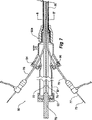
図1、図2、図3、図4および図5は、この発明の一実施例に従う送出装置2を示す。
DETAILED DESCRIPTION FIGS. 1, 2, 3, 4 and 5 show a delivery device 2 according to one embodiment of the present invention.
図1は、送出装置の斜視図を示す。図2は、図1と同じ図であるが、ステントグラフトおよびプッシャカテーテルを示すためにシースが引抜かれた状態を示す。図3は、一部が縦断面図で示された図1の装置の側面図を示す。図4は、図1における線4−4′に沿った横断面図を示す。図5は、図1における線5−5′に沿った横断面図を示す。 FIG. 1 shows a perspective view of the delivery device. FIG. 2 is the same view as FIG. 1, but with the sheath pulled out to show the stent graft and pusher catheter. FIG. 3 shows a side view of the apparatus of FIG. 1 partially shown in longitudinal section. FIG. 4 shows a cross-sectional view along line 4-4 ′ in FIG. FIG. 5 shows a cross-sectional view along line 5-5 ′ in FIG.
送出装置2は、ハンドル7の遠位から近位先細ノーズコーン拡張器11までおよび近位先細ノーズコーン拡張器11を貫いて延びるガイドワイヤカテーテル3を有する。ガイドワイヤカテーテル3は、遠位端においてハンドル7に接続されたプッシャまたは送出カテーテル4の通路または管腔5を通って長手方向に延びる。ガイドワイヤカテーテルのためのプッシャカテーテルの管腔5がプッシャカテーテル4の中心からオフセットされていることは、図3および図4において特に注目される。ガイドワイヤカテーテル3は、プッシャカテーテル4に対して長手方向におよび回転して動かすことができ、ハンドル7の遠位端におけるピン万力12によってプッシャカテーテル4に対して固定されることができる。導入器シース10は、送出カテーテル4を囲んで同軸に嵌まり、X線不透過性マーカ(図示せず)を任意に含む先細近位端13から、シースの遠位端15近くに取付けられたコネクタ弁およびマニピュレータ14まで延びている。
The delivery device 2 has a
コネクタ弁およびマニピュレータ14は、シリコーンディスクアセンブリを含む止血シールアセンブリと、シリコーンディスクアセンブリを通って延びるプッシャカテーテルおよび補助カテーテルとを備える自動封止弁であってもよい。代替的には、弁アセンブリは、キャプタ・バルブ(Captor Valve)(インディアナ州ブルーミントンのクック・インコーポレイテッド(Cook Inc.))などの手動操作可能な弁を含み得る。
The connector valve and
導入器シース10は、ノーズコーン拡張器11の近位に延び、患者に配置装置を導入している間は図1に示されるようにステントグラフト6を被覆する。導入器シース10は、配置装置が患者の脈管構造内の選択された位置にくると、配置中に、図2に示されるようにステントグラフト6を露出させるために遠位で引抜かれる。注射器および他の医療装置に接続するために、周知のルアーロックオスコネクタハブ20がガイドワイヤカテーテル10の遠位端に取付けられる。
ステントグラフトまたは移植可能装置6は、送出カテーテル4の近位でおよびノーズコーン拡張器11の遠位で、ガイドワイヤカテーテル3上を搬送される。コネクタ弁およびマニピュレータ14は、そこを通る流体の逆流を防ぐためにプッシャカテーテル4に対して封止を行なうシリコーンディスク9aを含む。ディスク9aは、ノーズコーン拡張器11およびプッシャカテーテル4を挿入するためのスリットを含む。コネクタ弁およびマニピュレータ14はまた、そこを通る流体を導入および吸引するための、管17が接続されたサイドアーム16を含む。ノーズコーン拡張器11は、ガイドワイヤカテーテルを通って延びる周知のおよび市販のワイヤガイド9(図5参照)上で血管アクセス部位にアクセスしかつ血管アクセス部位を拡張させるための先細近位端19を含む。
A stent graft or implantable device 6 is carried over the
ハンドル7のすぐ近位からプッシャカテーテル4の近位端まで、プッシャカテーテル4の長さに沿って、長手方向溝30がある。溝30には、補助カテーテル32が受けられる。拡張器31は補助カテーテル32の管腔を通って延び、補助ガイドワイヤ34は拡張器の管腔を通って延びる。実際には、特に図5から分かるように、補助カテーテル32はプッシャカテーテル4とシース10との間に保持される。
There is a
補助カテーテル32は、特に図4から分かるように、プッシャカテーテル4に対して封止されるようにコネクタ弁およびマニピュレータ14の遠位からシリコーンゴムシール9aを貫いて延びる。
The
ステントグラフト6は、生体適合性材料からなる管状本体22と、複数の自己拡張型ステント24とを備える。ステントグラフト6の、近位に延びる露出したステント25は、ノーズコーン拡張器11の遠位開口カプセル26上に受けられる。ステントグラフト6は開窓部27を有する。留置または補助ガイドワイヤ34は、特に図2から分かるように、ステントグラフト6の管腔内に延び、開窓部27を通って管腔を出る。補助カテーテル3
2および拡張器31は、ステントグラフト6のすぐ遠位で終端する。
The stent graft 6 includes a
2 and
配置のプロセスにおいて、ワイヤガイド9は、たとえば周知の経皮血管アクセスセルディンガー法を用いて導入器の針で血管に挿入される。送出装置2は、ガイドワイヤ上に導入されて、ステントグラフトの配置箇所まで操作される。プッシャカテーテル4の遠位端におけるハンドル7は、使用時に患者の外部に留まり、送出装置上に保持されたステントグラフト6の少なくとも近位端をトリガワイヤ(図示せず)を用いることによって解放するために用いられるトリガワイヤ解放機構8を搬送する。
In the placement process, the
補助ガイドワイヤ34は、送出装置にステントグラフトを積込んでいる間に開窓部27を通して延ばされる。配置中にシース10が引抜かれると、ステントグラフトを部分的にまたは完全に送出装置から解放しながらたとえば腎動脈に入ってそこに留まるように補助ガイドワイヤ34を操作できる。
The
次いで、拡張器31が腎動脈に入るまで補助ガイドワイヤ34上で拡張器31を前進させることができ、次いで、拡張器上で補助カテーテル32を前進させることができる。次いで、拡張器を引抜くことができ、たとえば腎動脈へのサイドアームステントのためのさらなる送出装置が、補助ガイドワイヤ34上で補助カテーテルを通して腎動脈の中に配置されることができ、配置されることができる。代替的には、拡張器を引抜く前に、補助ガイドワイヤを引抜くことができ、より硬いガイドワイヤを拡張器を通して腎動脈に前進させることができる。次いで、拡張器をさらなる送出装置と置換えることができる。次いで、主要なステントグラフトを完全に解放できる。この開窓部の事前カテーテル導入によって、枝動脈にサイドアームステントを配置するプロセスを簡略化できる。
The
したがって、本質的に、シースとプッシャカテーテルとの間に補助カテーテルまたは留置カテーテルを設置することによって、ステントグラフトを完全に解放する前に腎動脈の事前カテーテル導入が可能になる。 Thus, in essence, placing an auxiliary or indwelling catheter between the sheath and the pusher catheter allows pre-catheter introduction of the renal artery prior to complete release of the stent graft.
図6は、この発明の代替的な実施例を示す。図6は、プッシャカテーテルおよび導入器シースの断面図を示す。図6において、プッシャカテーテル50は2つの溝52および54を有し、各溝52および54に補助カテーテルまたは留置カテーテル56および58が受けられる。シース60は、プッシャカテーテル50ならびに補助カテーテルまたは留置カテーテル56および58を被覆する。補助カテーテルまたは留置カテーテル56および58は、プッシャカテーテルが依然として所定の位置にありながら腎動脈のための2つの開窓部に対して事前カテーテル導入を行なうために用いられることができる。3つ以上の開窓部が用いられる場合には、3つ以上の溝が存在し得て、各溝に補助カテーテルが存在し得る。
FIG. 6 shows an alternative embodiment of the present invention. FIG. 6 shows a cross-sectional view of the pusher catheter and introducer sheath. In FIG. 6,
図7は、この発明に従う配置装置の代替的な実施例のプッシャカテーテル、止血シールおよび導入器シースの縦断面図を示す。 FIG. 7 shows a longitudinal cross-sectional view of a pusher catheter, hemostatic seal and introducer sheath of an alternative embodiment of a deployment device according to the present invention.
この実施例では、プッシャカテーテル70は、ハンドル(図示せず)から止血シールおよび弁アセンブリ90の中におよび止血シールおよび弁アセンブリ90を貫いて延びる。プッシャカテーテル70は2つの溝72および74を有し、各溝72および74に補助カテーテルまたは留置カテーテル76および78が受けられる。溝72および74は、止血シールおよび弁アセンブリ90内部から近位に延びている。止血シールおよび弁アセンブリ90は、プッシャ70のためのシールおよび弁92と、補助カテーテル76および78のための2つの補助止血シール94および96とを含む。シース80は、止血シールおよび弁アセンブリ90の近位端90aに接続される。止血シールおよび弁アセンブリ90の本体91は細長いので、配置中にステントグラフト(図示せず)を露出させるために止血シールおよび弁アセンブリ90を遠位で引込むと、ステントグラフトを露出させるのに十分な引込みを可能にするように留置カテーテルを細長い溝72および74の中に置くことができる。
In this embodiment,
図8は、図7における矢印8−8′によって示される、図7に示される実施例のプッシャカテーテルおよび導入器シースの断面図を示す。図8では、プッシャカテーテル70は2つの溝72および74を有し、各溝72および74に補助カテーテルまたは留置カテーテル76および78が受けられる。補助カテーテル76および78のためにより大きな溝72および74を設けることができるように、プッシャカテーテル管腔82はプッシャカテーテル70の中心からオフセットされる。シース80は、プッシャカテーテル70ならびに補助カテーテルまたは留置カテーテル76および78を被覆する。補助ガイドワイヤ75および拡張器77は、図5との関連で記載された態様と同じ態様で補助カテーテル76および78を通って延び、たとえば腎動脈のための2つの開窓部の事前カテーテル導入のために用いられることができる。
FIG. 8 shows a cross-sectional view of the pusher catheter and introducer sheath of the embodiment shown in FIG. 7, indicated by arrows 8-8 ′ in FIG. In FIG. 8, the
図9は、この発明に従う配置装置の代替的な実施例のプッシャカテーテル、止血シールおよび導入器シース領域の縦断面図を示す。 FIG. 9 shows a longitudinal cross-sectional view of a pusher catheter, hemostatic seal and introducer sheath region of an alternative embodiment of a placement device according to the present invention.
この実施例では、導入装置100のハンドル102は、止血シール107および109によって補助カテーテル106および108をプッシャ110から分離できるように近位スプリッタ104を含む。導入装置上で、主要シース112は止血シールおよびマニピュレータ114から近位に延びている。止血シールおよびマニピュレータ114のシール部114aが確実に、溝110aおよび110bを有するプッシャ110ならびに補助カテーテル106および108を囲んで封止できるようにするために、プッシャ110と同軸でありかつプッシャ110の周りの補助シース116が、スプリッタ104に留められ、止血シールおよびマニピュレータ114の中に近位に延びている。この構成によって、シール114aは、ハンドル102と止血シールおよびマニピュレータ114との間のプッシャを囲んで封止できる。
In this example, the
主要シース112は、止血シールおよびマニピュレータ114が引込まれると補助シース116を内部に収めることができるようにするために直径がより大きな部分112aを有することができる。これによって、確実に、ステントグラフトを収容しているシースの部分ができる限り低背型になる。
The
なお、この実施例では、拡張器118および120を有する補助カテーテル106および108は近位に延び、これらの拡張器はステントグラフト122のすぐ遠位で終端する。
In this example,
この発明の一実施例の送出装置を用いるためのプロセスについて以下で説明する。この実施例では、配置装置は以下の構成要素を有する。以下の構成要素とは、ガイドワイヤカテーテルと、主要シースと、遠位開口上部キャップを有するノーズコーン拡張器と、開窓部を通る、上部キャップへの留置ガイドワイヤと、留置ガイドワイヤ上の補助カテーテルとであり、補助カテーテルは、内部に拡張器を有し、拡張器先端部まで延び、以下の構成要素とはさらにステントグラフトであり、ステントグラフトは、近位に延びる露出したステントと、直径低減繋ぎ材と、遠位保持部と、腎臓開窓部と、X線不透過性マーカとを有する。 A process for using the sending apparatus of one embodiment of the present invention will be described below. In this embodiment, the arrangement device has the following components. The following components include a guidewire catheter, a main sheath, a nose cone dilator with a distal open upper cap, an indwelling guidewire through the fenestration to the upper cap, and an assist on the indwelling guidewire An auxiliary catheter having a dilator inside and extending to the tip of the dilator, and the following components are further stent grafts, the stent graft having a diameter-reducing tether and a proximally extending exposed stent. It has a material, a distal holding part, a kidney fenestration part, and a radiopaque marker.
導入ステップは以下のとおりである。
(a) ステントグラフト本体上のマーカを用いて、標的血管およびステントグラフトの開窓部に対するN−S位置ならびに回転位置を考慮に入れて、配置装置を大動脈の中に
正しく位置決めする。
The introduction steps are as follows.
(A) Use markers on the stent graft body to correctly position the placement device in the aorta, taking into account the NS position and rotational position relative to the target vessel and the fenestration of the stent graft.
(b) ステントグラフトの遠位端が開くまで、継続して位置を確認しながら配置装置の主要シースを引抜く。この段階で、ステントグラフトの遠位端は、依然として遠位固着によって保持され、近位端は、配置装置の上部キャップに保持された露出したステントによって保持され、ステントグラフトの拡張は直径低減繋ぎ材によって制限される。 (B) Withdraw the main sheath of the deployment device while continuing to verify position until the distal end of the stent graft is open. At this stage, the distal end of the stent graft is still held by the distal anchor, the proximal end is held by the exposed stent held in the top cap of the deployment device, and the expansion of the stent graft is limited by the diameter-reducing binder. Is done.
(c) ステントグラフトの管腔を通して開窓部までまたは開窓部を通して、留置ガイドワイヤ上で補助カテーテルおよび拡張器を前進させる。(この段階で、上部キャップまたはカプセルは依然として、露出したステントおよび留置ガイドワイヤを保持している。)
(d) 開窓部の開口にまたは開窓部の漏斗部に補助カテーテルを位置決めする。
(C) Advance the auxiliary catheter and dilator over the indwelling guidewire through or through the lumen of the stent graft. (At this stage, the top cap or capsule still holds the exposed stent and indwelling guidewire.)
(D) Position the auxiliary catheter at the opening of the fenestration or at the funnel of the fenestration.
(e) 補助カテーテルの拡張器を取外す。
(f) 補助カテーテルを通して標的(たとえば、腎臓の)血管の中にさらなるカテーテルおよびさらなるガイドワイヤ(4〜5Fr)を前進させる。さらなるカテーテルは、アクセスを容易にするために、屈曲したまたはホッケースティック型の先端部を有していてもよい。
(E) Remove auxiliary catheter dilator.
(F) Advance an additional catheter and additional guidewire (4-5 Fr) through the auxiliary catheter and into the target (eg, renal) blood vessel. Additional catheters may have a bent or hockey stick type tip for easy access.
(g) ガイドワイヤをさらなるカテーテルから取外し、より硬いワイヤを標的血管(腎動脈)に再挿入する。 (G) Remove the guide wire from the further catheter and reinsert the stiffer wire into the target vessel (renal artery).
(h) 上部キャップから留置ワイヤガイドを回収し、留置ワイヤガイドを完全に引張り出す。 (H) Collect the indwelling wire guide from the upper cap and pull out the indwelling wire guide completely.
(i) さらなるカテーテルを取外し、標的血管の中のより硬いワイヤ上で拡張器を置換え、標的血管の中のより硬いワイヤ上で補助カテーテルを前進させる。拡張器を引抜く。 (I) Remove additional catheter, replace dilator on stiffer wire in target vessel, and advance auxiliary catheter over stiffer wire in target vessel. Pull out the dilator.
(j) 該当する場合、他の標的血管に対してステップ(c)から(i)を繰返す。
(k) 被覆されたステントを補助カテーテルを通して標的血管の中に前進させるが、解放しない。
(J) If applicable, repeat steps (c) to (i) for other target vessels.
(K) Advance the coated stent through the auxiliary catheter and into the target vessel, but do not release it.
(l) 直径低減繋ぎ材を解放する。
(m) ロッキングトリガワイヤを取外してガイドワイヤカテーテル上で上部キャップを前進させることによって上部キャップを解放し、上部露出ステントを解放する。
(L) Release the diameter-reducing binder.
(M) Release the upper cap by removing the locking trigger wire and advancing the upper cap over the guidewire catheter to release the upper exposed stent.
(n) ステントグラフトの遠位アタッチメントを解放する。
(o) 標的血管から補助カテーテルを引抜き、開窓部同士の間におよび標的血管の中に被覆されたステントを配置し、必要であれば主要ステントグラフト内の広がりを含んでバルーンが膨らむ。
(N) Release the distal attachment of the stent graft.
(O) The auxiliary catheter is withdrawn from the target blood vessel, and a covered stent is placed between the fenestrations and in the target blood vessel, and the balloon is inflated, including the extent in the main stent graft, if necessary.
(p) 標的血管から補助カテーテルおよびさらにガイドワイヤを取外し、補助カテーテルおよびガイドワイヤをシステムから引抜く。 (P) Remove the auxiliary catheter and further guide wire from the target vessel and withdraw the auxiliary catheter and guide wire from the system.
(q) アセンブリ全体を引抜くか、またはさらなる配置のために主要シースを所定の位置に残したままにする。さらなる配置は、分岐した遠位構成要素を含んでいてもよい。 (Q) Withdraw the entire assembly or leave the main sheath in place for further placement. Further arrangements may include a bifurcated distal component.
本明細書を通じて、この発明の範囲に関してさまざまな指摘がなされてきたが、この発明はこれらのいずれか一つに限定されるものではなく、組合せられた2つ以上のこれらに
あってもよい。例は限定の目的ではなく単に説明の目的で与えられている。
Throughout the specification, various indications have been made regarding the scope of the present invention, but the present invention is not limited to any one of these, and there may be two or more of these combined. The examples are given for illustrative purposes only and not for purposes of limitation.
本明細書および後に続く特許請求の範囲を通じて、文脈が特に定めない限り、「備える(comprise)」および「含む(include)」という単語、ならびに「備えている(comprising)」および「含んでいる(including)」などの変形例は、記載される完全体または完全体の群を包含するが他の完全体または完全体の群を排除しないことを意味するように理解される。 Throughout this specification and the claims that follow, the words “comprise” and “include”, and “comprising” and “include,” unless the context clearly dictates otherwise. Variations such as “including” are understood to mean including the complete or complete group described, but not excluding other complete or complete groups.
Claims (16)
Applications Claiming Priority (3)
| Application Number | Priority Date | Filing Date | Title |
|---|---|---|---|
| US84770806P | 2006-09-28 | 2006-09-28 | |
| US60/847,708 | 2006-09-28 | ||
| PCT/US2007/020949 WO2008042270A1 (en) | 2006-09-28 | 2007-09-28 | Endovascular delivery device |
Publications (3)
| Publication Number | Publication Date |
|---|---|
| JP2010504821A JP2010504821A (en) | 2010-02-18 |
| JP2010504821A5 JP2010504821A5 (en) | 2010-11-25 |
| JP5109193B2 true JP5109193B2 (en) | 2012-12-26 |
Family
ID=38996617
Family Applications (1)
| Application Number | Title | Priority Date | Filing Date |
|---|---|---|---|
| JP2009530432A Active JP5109193B2 (en) | 2006-09-28 | 2007-09-28 | Intravascular delivery device |
Country Status (6)
| Country | Link |
|---|---|
| US (1) | US8118854B2 (en) |
| EP (1) | EP2066270B1 (en) |
| JP (1) | JP5109193B2 (en) |
| AT (1) | ATE523168T1 (en) |
| AU (1) | AU2007305387B2 (en) |
| WO (1) | WO2008042270A1 (en) |
Families Citing this family (60)
| Publication number | Priority date | Publication date | Assignee | Title |
|---|---|---|---|---|
| CA2649705C (en) * | 2006-04-19 | 2015-12-01 | William A. Cook Australia Pty. Ltd | Twin bifurcated stent graft |
| US8523931B2 (en) | 2007-01-12 | 2013-09-03 | Endologix, Inc. | Dual concentric guidewire and methods of bifurcated graft deployment |
| US8317856B2 (en) | 2007-03-05 | 2012-11-27 | Endospan Ltd. | Multi-component expandable supportive bifurcated endoluminal grafts and methods for using same |
| US8221494B2 (en) | 2008-02-22 | 2012-07-17 | Endologix, Inc. | Apparatus and method of placement of a graft or graft system |
| US8236040B2 (en) | 2008-04-11 | 2012-08-07 | Endologix, Inc. | Bifurcated graft deployment systems and methods |
| US8668668B2 (en) | 2008-05-14 | 2014-03-11 | Onset Medical Corporation | Expandable iliac sheath and method of use |
| US8728153B2 (en) * | 2008-05-14 | 2014-05-20 | Onset Medical Corporation | Expandable transapical sheath and method of use |
| US8562559B2 (en) | 2008-05-14 | 2013-10-22 | Onset Medical Corporation | Expandable iliac sheath and method of use |
| EP2293838B1 (en) | 2008-07-01 | 2012-08-08 | Endologix, Inc. | Catheter system |
| AU2009200350B1 (en) * | 2009-02-02 | 2009-07-16 | Cook Incorporated | Preloaded stent graft delivery device |
| CN101836911A (en) | 2009-03-18 | 2010-09-22 | 微创医疗器械(上海)有限公司 | Collateral filmed stent |
| US8945202B2 (en) | 2009-04-28 | 2015-02-03 | Endologix, Inc. | Fenestrated prosthesis |
| CN101897629B (en) * | 2009-05-26 | 2013-08-07 | 上海微创医疗器械(集团)有限公司 | Branched membrane-covered support conveying system and conveying method thereof |
| GB2481357B (en) * | 2009-05-26 | 2016-12-14 | Microport Endovascular (Shanghai) Co Ltd | Delivery system for branched stent graft |
| CA3009244C (en) | 2009-06-23 | 2020-04-28 | Endospan Ltd. | Vascular prostheses for treating aneurysms |
| US8663306B2 (en) * | 2010-03-19 | 2014-03-04 | Cook Medical Technologies Llc | Introducer with extension |
| AU2010202487B1 (en) * | 2010-06-15 | 2011-07-28 | Cook Incorporated | Pre-loaded multiport delivery device |
| CA2747610C (en) * | 2010-08-13 | 2014-09-16 | Cook Medical Technologies Llc | Precannulated fenestration |
| WO2012061526A2 (en) | 2010-11-02 | 2012-05-10 | Endologix, Inc. | Apparatus and method of placement of a graft or graft system |
| US9566149B2 (en) | 2010-11-16 | 2017-02-14 | W. L. Gore & Associates, Inc. | Devices and methods for in situ fenestration of a stent-graft at the site of a branch vessel |
| JP6294669B2 (en) | 2011-03-01 | 2018-03-14 | エンドロジックス、インク | Catheter system and method of use thereof |
| US9522064B2 (en) | 2011-05-16 | 2016-12-20 | Hlt, Inc. | Inversion delivery device and method for a prosthesis |
| US9839510B2 (en) | 2011-08-28 | 2017-12-12 | Endospan Ltd. | Stent-grafts with post-deployment variable radial displacement |
| US9427339B2 (en) | 2011-10-30 | 2016-08-30 | Endospan Ltd. | Triple-collar stent-graft |
| US8728148B2 (en) | 2011-11-09 | 2014-05-20 | Cook Medical Technologies Llc | Diameter reducing tie arrangement for endoluminal prosthesis |
| US9597204B2 (en) | 2011-12-04 | 2017-03-21 | Endospan Ltd. | Branched stent-graft system |
| AU2012200735C1 (en) | 2012-02-08 | 2013-01-24 | Cook Medical Technologies Llc | Orientation markers for endovascular delivery system |
| EP2818139A4 (en) | 2012-02-24 | 2015-10-21 | Terumo Corp | Stent-graft delivery device |
| US9393140B2 (en) * | 2012-04-27 | 2016-07-19 | Medtronic Vascular, Inc. | Reconfigurable stent-graft delivery system and method of use |
| WO2013171730A1 (en) | 2012-05-15 | 2013-11-21 | Endospan Ltd. | Stent-graft with fixation elements that are radially confined for delivery |
| US9763817B2 (en) * | 2012-10-29 | 2017-09-19 | Cook Medical Technologies Llc | Delivery system with curved preloaded catheter |
| WO2014108895A2 (en) | 2013-01-08 | 2014-07-17 | Endospan Ltd. | Minimization of stent-graft migration during implantation |
| US9439793B2 (en) | 2013-03-12 | 2016-09-13 | Cook Medical Technologies Llc | Extension for iliac branch delivery device and methods of using the same |
| US10130501B2 (en) | 2013-03-12 | 2018-11-20 | Cook Medical Technologies Llc | Delivery device with an extension sheath and methods of using the same |
| US10603197B2 (en) | 2013-11-19 | 2020-03-31 | Endospan Ltd. | Stent system with radial-expansion locking |
| CA2963135A1 (en) | 2014-10-13 | 2016-04-21 | Hlt, Inc. | Inversion delivery device and method for a prosthesis |
| WO2016090112A1 (en) | 2014-12-04 | 2016-06-09 | Trivascular, Inc. | Internal iliac preservation devices and methods |
| EP3068339B1 (en) | 2014-12-18 | 2017-11-01 | Endospan Ltd. | Endovascular stent-graft with fatigue-resistant lateral tube |
| US10231858B2 (en) | 2014-12-22 | 2019-03-19 | Cook Medical Technologies Llc | Delivery system for preloaded fenestrated device |
| EP4417169A2 (en) | 2015-06-30 | 2024-08-21 | Endologix LLC | Locking assembly for coupling guidewire to delivery system |
| KR101709601B1 (en) * | 2016-05-30 | 2017-02-23 | 주식회사 에스앤지바이오텍 | Inserting Device of Stent Having Guide Member Having Fixing Part |
| US10646689B2 (en) | 2016-07-29 | 2020-05-12 | Cephea Valve Technologies, Inc. | Mechanical interlock for catheters |
| US10661052B2 (en) | 2016-07-29 | 2020-05-26 | Cephea Valve Technologies, Inc. | Intravascular device delivery sheath |
| US11324495B2 (en) | 2016-07-29 | 2022-05-10 | Cephea Valve Technologies, Inc. | Systems and methods for delivering an intravascular device to the mitral annulus |
| US10974027B2 (en) | 2016-07-29 | 2021-04-13 | Cephea Valve Technologies, Inc. | Combination steerable catheter and systems |
| US10933216B2 (en) * | 2016-08-29 | 2021-03-02 | Cephea Valve Technologies, Inc. | Multilumen catheter |
| US11109967B2 (en) | 2016-08-29 | 2021-09-07 | Cephea Valve Technologies, Inc. | Systems and methods for loading and deploying an intravascular device |
| US11045315B2 (en) | 2016-08-29 | 2021-06-29 | Cephea Valve Technologies, Inc. | Methods of steering and delivery of intravascular devices |
| US10874512B2 (en) | 2016-10-05 | 2020-12-29 | Cephea Valve Technologies, Inc. | System and methods for delivering and deploying an artificial heart valve within the mitral annulus |
| US10500079B2 (en) | 2016-10-27 | 2019-12-10 | Cook Medical Technologies Llc | Preloaded branch wire loop constraint |
| EP3369402A1 (en) | 2017-02-28 | 2018-09-05 | Cook Medical Technologies LLC | Delivery system for a preloaded fenestrated device having a thumbwheel sheath deployment |
| EP3369401B1 (en) | 2017-02-28 | 2024-07-10 | Cook Medical Technologies LLC | Delivery system for a preloaded fenestrated device having a ratcheted wire release |
| CN110678153A (en) * | 2017-04-06 | 2020-01-10 | 瑞弗罗医疗公司 | Delivery system for stents with protruding features |
| US11096810B2 (en) | 2017-11-29 | 2021-08-24 | Cook Medical Technologies Llc | Preloaded pusher tip for endografts |
| EP3494936A1 (en) * | 2017-12-05 | 2019-06-12 | Cook Medical Technologies LLC | Endograft delivery device assembly |
| EP3508172B1 (en) | 2018-01-03 | 2020-08-19 | Cook Medical Technologies LLC | Pre-loaded multiport delivery device |
| JP2022508647A (en) * | 2018-10-08 | 2022-01-19 | リフロー メディカル インコーポレイテッド | Stent delivery system with protruding mechanism |
| US11724068B2 (en) | 2018-11-16 | 2023-08-15 | Cephea Valve Technologies, Inc. | Intravascular delivery system |
| US11850174B2 (en) | 2018-12-27 | 2023-12-26 | Lifetech Scientific (Shenzhen) Co, Ltd. | Delivery apparatus and system |
| AU2019203004B1 (en) | 2019-04-30 | 2019-09-12 | Cook Medical Technologies Llc | A line pull assembly for a prosthetic delivery device |
Family Cites Families (19)
| Publication number | Priority date | Publication date | Assignee | Title |
|---|---|---|---|---|
| US5693083A (en) * | 1983-12-09 | 1997-12-02 | Endovascular Technologies, Inc. | Thoracic graft and delivery catheter |
| CA2125258C (en) * | 1993-08-05 | 1998-12-22 | Dinah B Quiachon | Multicapsule intraluminal grafting system and method |
| US5683451A (en) * | 1994-06-08 | 1997-11-04 | Cardiovascular Concepts, Inc. | Apparatus and methods for deployment release of intraluminal prostheses |
| US6596020B2 (en) * | 1996-11-04 | 2003-07-22 | Advanced Stent Technologies, Inc. | Method of delivering a stent with a side opening |
| US6379365B1 (en) * | 1999-03-29 | 2002-04-30 | Alexis Diaz | Stent delivery catheter system having grooved shaft |
| WO2003002033A1 (en) | 2001-06-27 | 2003-01-09 | Salviac Limited | A catheter |
| CA2466270C (en) * | 2001-11-29 | 2010-09-14 | Cook Incorporated | Medical device delivery system |
| US6641606B2 (en) * | 2001-12-20 | 2003-11-04 | Cleveland Clinic Foundation | Delivery system and method for deploying an endovascular prosthesis |
| AU2002951147A0 (en) * | 2002-09-02 | 2002-09-19 | Cook Incorporated | Branch grafting device and method |
| US7130700B2 (en) * | 2002-11-19 | 2006-10-31 | Medtronic, Inc. | Multilumen body for an implantable medical device |
| WO2004071352A1 (en) | 2003-02-14 | 2004-08-26 | Salviac Limited | Stent delivery and deployment system |
| AU2004228046B2 (en) * | 2003-04-03 | 2009-02-05 | Cook Incorporated | Branch stent graft deployment and method |
| EP1715912A2 (en) | 2004-01-16 | 2006-11-02 | Rigshospitalet | Double-wire non-trapping angioplasty catheter |
| US8043354B2 (en) * | 2004-06-16 | 2011-10-25 | William A. Cook Australia Pty. Ltd. | Thoracic deployment device and stent graft |
| EP1791498B1 (en) * | 2004-09-22 | 2018-02-28 | Cook Medical Technologies, LLC | Stent graft with integral side arm |
| US7699883B2 (en) * | 2004-10-25 | 2010-04-20 | Myles Douglas | Vascular graft and deployment system |
| US8287583B2 (en) * | 2005-01-10 | 2012-10-16 | Taheri Laduca Llc | Apparatus and method for deploying an implantable device within the body |
| AU2006280948B2 (en) | 2005-08-18 | 2011-10-27 | Cook Incorporated | Assembly of stent grafts |
| US7867270B2 (en) * | 2006-06-02 | 2011-01-11 | William A. Cook Australia Pty. Ltd. | Multi-port delivery device |
-
2007
- 2007-09-28 JP JP2009530432A patent/JP5109193B2/en active Active
- 2007-09-28 WO PCT/US2007/020949 patent/WO2008042270A1/en active Application Filing
- 2007-09-28 US US11/904,834 patent/US8118854B2/en active Active
- 2007-09-28 EP EP07838999A patent/EP2066270B1/en active Active
- 2007-09-28 AT AT07838999T patent/ATE523168T1/en not_active IP Right Cessation
- 2007-09-28 AU AU2007305387A patent/AU2007305387B2/en active Active
Also Published As
| Publication number | Publication date |
|---|---|
| ATE523168T1 (en) | 2011-09-15 |
| EP2066270A1 (en) | 2009-06-10 |
| WO2008042270A1 (en) | 2008-04-10 |
| JP2010504821A (en) | 2010-02-18 |
| US20080109065A1 (en) | 2008-05-08 |
| AU2007305387B2 (en) | 2012-08-09 |
| AU2007305387A1 (en) | 2008-04-10 |
| US8118854B2 (en) | 2012-02-21 |
| EP2066270B1 (en) | 2011-09-07 |
Similar Documents
| Publication | Publication Date | Title |
|---|---|---|
| JP5109193B2 (en) | Intravascular delivery device | |
| US10413435B2 (en) | Pre-loaded multiport delivery device | |
| US8864808B2 (en) | Endoluminal delivery assembly | |
| US8043354B2 (en) | Thoracic deployment device and stent graft | |
| US8292951B2 (en) | Tethered pop up branch structure stent graft and method | |
| US8753385B2 (en) | Preloaded stent graft delivery device | |
| EP3138537B1 (en) | Prosthesis fixation system | |
| US20030204243A1 (en) | Stent graft with integrated valve device and method | |
| US20140257464A1 (en) | Endovascular Grafts for Treating the Iliac Arteries and Methods of Delivery and Deployment Thereof | |
| US20210353445A1 (en) | Pre-loaded multiport delivery device | |
| US20140121751A1 (en) | Cannula attachment in endoluminal delivery devices | |
| US11096810B2 (en) | Preloaded pusher tip for endografts |
Legal Events
| Date | Code | Title | Description |
|---|---|---|---|
| A521 | Request for written amendment filed |
Free format text: JAPANESE INTERMEDIATE CODE: A523 Effective date: 20100927 |
|
| A621 | Written request for application examination |
Free format text: JAPANESE INTERMEDIATE CODE: A621 Effective date: 20100927 |
|
| A131 | Notification of reasons for refusal |
Free format text: JAPANESE INTERMEDIATE CODE: A131 Effective date: 20120424 |
|
| A977 | Report on retrieval |
Free format text: JAPANESE INTERMEDIATE CODE: A971007 Effective date: 20120427 |
|
| TRDD | Decision of grant or rejection written | ||
| A01 | Written decision to grant a patent or to grant a registration (utility model) |
Free format text: JAPANESE INTERMEDIATE CODE: A01 Effective date: 20120821 |
|
| A01 | Written decision to grant a patent or to grant a registration (utility model) |
Free format text: JAPANESE INTERMEDIATE CODE: A01 |
|
| A711 | Notification of change in applicant |
Free format text: JAPANESE INTERMEDIATE CODE: A711 Effective date: 20120918 |
|
| A61 | First payment of annual fees (during grant procedure) |
Free format text: JAPANESE INTERMEDIATE CODE: A61 Effective date: 20120919 |
|
| A521 | Request for written amendment filed |
Free format text: JAPANESE INTERMEDIATE CODE: A821 Effective date: 20120918 |
|
| FPAY | Renewal fee payment (event date is renewal date of database) |
Free format text: PAYMENT UNTIL: 20151019 Year of fee payment: 3 |
|
| R150 | Certificate of patent or registration of utility model |
Ref document number: 5109193 Country of ref document: JP Free format text: JAPANESE INTERMEDIATE CODE: R150 Free format text: JAPANESE INTERMEDIATE CODE: R150 |
|
| R250 | Receipt of annual fees |
Free format text: JAPANESE INTERMEDIATE CODE: R250 |
|
| R250 | Receipt of annual fees |
Free format text: JAPANESE INTERMEDIATE CODE: R250 |
|
| R250 | Receipt of annual fees |
Free format text: JAPANESE INTERMEDIATE CODE: R250 |
|
| R250 | Receipt of annual fees |
Free format text: JAPANESE INTERMEDIATE CODE: R250 |
|
| R250 | Receipt of annual fees |
Free format text: JAPANESE INTERMEDIATE CODE: R250 |
|
| R250 | Receipt of annual fees |
Free format text: JAPANESE INTERMEDIATE CODE: R250 |
|
| R250 | Receipt of annual fees |
Free format text: JAPANESE INTERMEDIATE CODE: R250 |
|
| R250 | Receipt of annual fees |
Free format text: JAPANESE INTERMEDIATE CODE: R250 |
|
| R250 | Receipt of annual fees |
Free format text: JAPANESE INTERMEDIATE CODE: R250 |