JP5107233B2 - Release clip - Google Patents
Release clip Download PDFInfo
- Publication number
- JP5107233B2 JP5107233B2 JP2008507583A JP2008507583A JP5107233B2 JP 5107233 B2 JP5107233 B2 JP 5107233B2 JP 2008507583 A JP2008507583 A JP 2008507583A JP 2008507583 A JP2008507583 A JP 2008507583A JP 5107233 B2 JP5107233 B2 JP 5107233B2
- Authority
- JP
- Japan
- Prior art keywords
- release clip
- release
- flange
- hinge
- tube
- Prior art date
- Legal status (The legal status is an assumption and is not a legal conclusion. Google has not performed a legal analysis and makes no representation as to the accuracy of the status listed.)
- Expired - Fee Related
Links
Images


Classifications
-
- F—MECHANICAL ENGINEERING; LIGHTING; HEATING; WEAPONS; BLASTING
- F16—ENGINEERING ELEMENTS AND UNITS; GENERAL MEASURES FOR PRODUCING AND MAINTAINING EFFECTIVE FUNCTIONING OF MACHINES OR INSTALLATIONS; THERMAL INSULATION IN GENERAL
- F16L—PIPES; JOINTS OR FITTINGS FOR PIPES; SUPPORTS FOR PIPES, CABLES OR PROTECTIVE TUBING; MEANS FOR THERMAL INSULATION IN GENERAL
- F16L37/00—Couplings of the quick-acting type
- F16L37/08—Couplings of the quick-acting type in which the connection between abutting or axially overlapping ends is maintained by locking members
- F16L37/084—Couplings of the quick-acting type in which the connection between abutting or axially overlapping ends is maintained by locking members combined with automatic locking
- F16L37/098—Couplings of the quick-acting type in which the connection between abutting or axially overlapping ends is maintained by locking members combined with automatic locking by means of flexible hooks
- F16L37/0982—Couplings of the quick-acting type in which the connection between abutting or axially overlapping ends is maintained by locking members combined with automatic locking by means of flexible hooks with a separate member for releasing the coupling
-
- B—PERFORMING OPERATIONS; TRANSPORTING
- B25—HAND TOOLS; PORTABLE POWER-DRIVEN TOOLS; MANIPULATORS
- B25B—TOOLS OR BENCH DEVICES NOT OTHERWISE PROVIDED FOR, FOR FASTENING, CONNECTING, DISENGAGING OR HOLDING
- B25B27/00—Hand tools, specially adapted for fitting together or separating parts or objects whether or not involving some deformation, not otherwise provided for
- B25B27/02—Hand tools, specially adapted for fitting together or separating parts or objects whether or not involving some deformation, not otherwise provided for for connecting objects by press fit or detaching same
- B25B27/10—Hand tools, specially adapted for fitting together or separating parts or objects whether or not involving some deformation, not otherwise provided for for connecting objects by press fit or detaching same inserting fittings into hoses
-
- F—MECHANICAL ENGINEERING; LIGHTING; HEATING; WEAPONS; BLASTING
- F16—ENGINEERING ELEMENTS AND UNITS; GENERAL MEASURES FOR PRODUCING AND MAINTAINING EFFECTIVE FUNCTIONING OF MACHINES OR INSTALLATIONS; THERMAL INSULATION IN GENERAL
- F16L—PIPES; JOINTS OR FITTINGS FOR PIPES; SUPPORTS FOR PIPES, CABLES OR PROTECTIVE TUBING; MEANS FOR THERMAL INSULATION IN GENERAL
- F16L37/00—Couplings of the quick-acting type
- F16L37/08—Couplings of the quick-acting type in which the connection between abutting or axially overlapping ends is maintained by locking members
- F16L37/084—Couplings of the quick-acting type in which the connection between abutting or axially overlapping ends is maintained by locking members combined with automatic locking
- F16L37/092—Couplings of the quick-acting type in which the connection between abutting or axially overlapping ends is maintained by locking members combined with automatic locking by means of elements wedged between the pipe and the frusto-conical surface of the body of the connector
- F16L37/0925—Couplings of the quick-acting type in which the connection between abutting or axially overlapping ends is maintained by locking members combined with automatic locking by means of elements wedged between the pipe and the frusto-conical surface of the body of the connector with rings which bite into the wall of the pipe
-
- F—MECHANICAL ENGINEERING; LIGHTING; HEATING; WEAPONS; BLASTING
- F16—ENGINEERING ELEMENTS AND UNITS; GENERAL MEASURES FOR PRODUCING AND MAINTAINING EFFECTIVE FUNCTIONING OF MACHINES OR INSTALLATIONS; THERMAL INSULATION IN GENERAL
- F16L—PIPES; JOINTS OR FITTINGS FOR PIPES; SUPPORTS FOR PIPES, CABLES OR PROTECTIVE TUBING; MEANS FOR THERMAL INSULATION IN GENERAL
- F16L37/00—Couplings of the quick-acting type
- F16L37/08—Couplings of the quick-acting type in which the connection between abutting or axially overlapping ends is maintained by locking members
- F16L37/084—Couplings of the quick-acting type in which the connection between abutting or axially overlapping ends is maintained by locking members combined with automatic locking
- F16L37/092—Couplings of the quick-acting type in which the connection between abutting or axially overlapping ends is maintained by locking members combined with automatic locking by means of elements wedged between the pipe and the frusto-conical surface of the body of the connector
- F16L37/0926—Couplings of the quick-acting type in which the connection between abutting or axially overlapping ends is maintained by locking members combined with automatic locking by means of elements wedged between the pipe and the frusto-conical surface of the body of the connector with an inner support sleeve arranged within the pipe
-
- F—MECHANICAL ENGINEERING; LIGHTING; HEATING; WEAPONS; BLASTING
- F16—ENGINEERING ELEMENTS AND UNITS; GENERAL MEASURES FOR PRODUCING AND MAINTAINING EFFECTIVE FUNCTIONING OF MACHINES OR INSTALLATIONS; THERMAL INSULATION IN GENERAL
- F16L—PIPES; JOINTS OR FITTINGS FOR PIPES; SUPPORTS FOR PIPES, CABLES OR PROTECTIVE TUBING; MEANS FOR THERMAL INSULATION IN GENERAL
- F16L37/00—Couplings of the quick-acting type
- F16L37/08—Couplings of the quick-acting type in which the connection between abutting or axially overlapping ends is maintained by locking members
- F16L37/084—Couplings of the quick-acting type in which the connection between abutting or axially overlapping ends is maintained by locking members combined with automatic locking
- F16L37/092—Couplings of the quick-acting type in which the connection between abutting or axially overlapping ends is maintained by locking members combined with automatic locking by means of elements wedged between the pipe and the frusto-conical surface of the body of the connector
- F16L37/0927—Couplings of the quick-acting type in which the connection between abutting or axially overlapping ends is maintained by locking members combined with automatic locking by means of elements wedged between the pipe and the frusto-conical surface of the body of the connector the wedge element being axially displaceable for releasing the coupling
Abstract
Description
本発明は、チューブコネクタからチューブを解放するためのリリースクリップに関する。リリースクリップは、解放すべきチューブの周囲のショルダとして提供され、チューブの外周のコネクタ内に押込まれる。 The present invention relates to a release clip for releasing a tube from a tube connector. The release clip is provided as a shoulder around the tube to be released and is pushed into the connector on the outer periphery of the tube.
チューブコネクタ、特にプッシュ・イン形式の迅速解放コネクタに関しては、チューブがチューブコネクタ内に取付けられた後に、チューブを解放することがしばしば必要になる。これには、例えば、機械的故障または漏洩のためチューブを交換したい場合、改造のための分解の一環として、または不完全な組立体であることによる等の多くの異なる理由がある。 For tube connectors, particularly push-in type quick release connectors, it is often necessary to release the tube after it has been installed in the tube connector. There are many different reasons for this, for example if you want to replace the tube due to mechanical failure or leakage, as part of a disassembly for modification or due to an incomplete assembly.
例えば下記特許文献1から4の従来技術から、チューブコネクタ用の種々のリリース器具およびリリース工具が知られている。
For example, various release devices and release tools for tube connectors are known from the prior art disclosed in
特許文献1には、チューブがロッキングリングにより固定される構成のチューブコネクタ内に押込まれる工具が開示されている。この既知の工具は、チューブとの係合から離脱させるべくロッキングリングを充分に引っ張って、チューブを解放させるものである。本発明では、リリースクリップが、ハウジング内の円錐面に沿ってロッキングリングを押しやり、これによりロッキングリングがその周方向に割れ目部する。このため、ロッキングリングは、円錐面に沿って押されるときにその固有の弾性に基いて拡大し、チューブの周囲のグリップ力およびクランプ力を喪失する。これにより、チューブが解放され、引出すことが可能になる。
チューブコネクタ用のリリースクリップは容易に取付けられるべきであり、幾つかの理由から、チューブコネクタとは別体に構成しなければならない。別体として構成することにより、コネクタが不意に解放されることが防止される(不意の解放は一体形リリース器具の場合に生じる)。また、別体として構成すると、コネクタをより少数の部品で構成できるため、実際のコネクタをより安価に製造できる。更に、リリースクリップは、使用中にコネクタ(またはチューブ)を壊したり傷付けないように設計すべきである。また、容易に使用できなくてはならない。更に、関連工具を使用しないで、手で操作できるようにすることも本発明の一目的である。 Release clips for tube connectors should be easy to install and must be constructed separately from the tube connector for several reasons. Configuring as a separate body prevents the connector from being released unexpectedly (the unexpected release occurs in the case of an integral release device). Further, when configured as a separate body, the connector can be configured with a smaller number of parts, and thus an actual connector can be manufactured at a lower cost. In addition, the release clip should be designed so that it does not break or damage the connector (or tube) during use. It must also be easy to use. Furthermore, it is an object of the present invention to enable manual operation without using a related tool.
本発明の第一態様によれば、コネクタ要素内に固定された状態から管状要素の端部を解放させることができるリリースクリップであって、リリースクリップは、管状本体を備え、管状本体には、該管状本体の長手方向軸線に沿って延びる割れ目部が形成され、管状本体は、この一領域により形成された一体ヒンジを有し、リリースクリップは、管状要素への取付けおよび管状要素からの取外しが可能であることを特徴とするリリースクリップが提供される。 According to a first aspect of the present invention, a release clip capable of releasing an end of a tubular element from a state of being fixed in a connector element , the release clip comprising a tubular body, A split is formed extending along the longitudinal axis of the tubular body, the tubular body having an integral hinge formed by this region, and the release clip is attached to and removed from the tubular element. A release clip is provided that is characterized in that it is possible.
好ましくは、一体ヒンジは、管状本体の薄い壁厚の一領域により少なくとも一部が形成され、一体ヒンジはまた、割れ目部とはほぼ反対側に配置されている。この構成により、閉じ込められたスペース内で使用できるコンパクトな器具を提供できる。リリースクリップは、好ましくは、プラスチック材料で形成されかつ一体ヒンジ領域は管状要素への取付けおよび取外しを可能にする程度の可撓性を有している。リリースクリップは、射出成形またはプラスチック材料に適した他の任意の製造方法により、単一ユニットとして形成できる。 Preferably, the integral hinge is formed at least in part by a region of the thin wall thickness of the tubular body, and the integral hinge is also located generally opposite the crack. With this configuration, a compact instrument that can be used in a confined space can be provided. The release clip is preferably formed of a plastic material and the integral hinge region is flexible enough to allow attachment and removal from the tubular element. The release clip can be formed as a single unit by injection molding or any other manufacturing method suitable for plastic materials.
これにより、流体を流すシステムに使用するチューブコネクタ用リリースクリップが提供される。チューブコネクタは、好ましくは、流体が通って流れる開口を有し、コネクタ内に挿入されるチューブを固定しかつシーリング連結するように構成されている。コネクタの内部には、貫通開口の周囲に沿う円錐部分が設けられ、該円錐部分は、コネクタの開口に向かう方向にテーパした直径を有している。コネクタには更に、円錐部分とコネクタの開口との間にシーリングリングが設けられている。コネクタの円錐部分には、チューブをグリップする円形グリッピングリングが取付けられている。このグリッピングリングは、コネクタ内部の円錐部分にほぼ一致する外側円錐面を有している。ロッキングリングはその円周方向に割れ目部しており、ロッキングリングが内側円錐部分に沿ってコネクタの長手方向に移動するときに、ロッキングリングの直径を変えることを可能にするセクション(部分)を有している。 This provides a tube connector release clip for use in a fluid flow system. The tube connector preferably has an opening through which fluid flows and is configured to secure and sealingly connect a tube inserted into the connector. Inside the connector, a conical portion is provided along the periphery of the through opening, and the conical portion has a diameter that tapers in a direction toward the connector opening. The connector further includes a sealing ring between the conical portion and the connector opening. A circular gripping ring for gripping the tube is attached to the conical portion of the connector. The gripping ring has an outer conical surface that substantially coincides with the conical portion inside the connector. The locking ring is split in its circumferential direction and has a section that allows the locking ring diameter to change as the locking ring moves along the inner conical portion in the longitudinal direction of the connector. is doing.
リリースボディの長手方向長さは、少なくとも、ハウジングの開口からグリッパリングまでの距離に等しい。 The longitudinal length of the release body is at least equal to the distance from the housing opening to the gripper ring.
本発明によるリリースクリップは、チューブがコネクタ内に挿入され、次にグリッパリングをコネクタ内で内側円錐部分に沿って、大きい直径を有する円錐部分に向けて押込まれる形式のチューブコネクタに適合される。グリッパリングは割れ目部しているので拡大でき、チューブの外径はコネクタ内でグリッパリングの内側を通る。次にチューブが、グリッパリングを通って完全に挿入されると、再びチューブを引出そうと試みることにより、グリッパリングは、コネクタ内で内側円錐部分に沿って、小さい直径を有する円錐部分に向かって移動し、グリッパリングは(依然として割れ目部しているため)、チューブの外面の周囲で圧縮されかつ緊締される。このため、グリッパリングは、チューブの外面をグリップし、コネクタ内に保持する。 The release clip according to the invention is adapted to a tube connector of the type in which the tube is inserted into the connector and then the gripper ring is pushed in the connector along the inner conical part towards the conical part having a large diameter. . Since the gripper ring is split, it can be enlarged, and the outer diameter of the tube passes inside the gripper ring in the connector. When the tube is then fully inserted through the gripper ring, the gripper ring is directed along the inner conical portion in the connector toward the conical portion having a small diameter by attempting to pull the tube out again. Moving, the gripper ring is compressed and clamped around the outer surface of the tube (because it is still cracked). For this reason, the gripper ring grips the outer surface of the tube and holds it in the connector.
本発明によるリリースクリップに使用するグリッパリングの好ましい実施形態では、チューブの周囲で、グリッパリングの上方の内周面に円錐部分が設けられている。これにより、リリースクリップがグリッパリングに対して押付けられるときにリリースクリップを「キャッチ」することが確保される一方、同時に、リリースクリップはグリッパリングを拡大(グリッパリングが割れ目部していることによる)する補助をなし、チューブを容易に取外すことができるようにする。 In a preferred embodiment of the gripper ring used in the release clip according to the invention, a conical part is provided on the inner peripheral surface above the gripper ring around the tube. This ensures that the release clip "catches" when it is pressed against the gripper ring, while at the same time the release clip expands the gripper ring (due to the gripper ring being split) To help remove the tube easily.
使用時に、リリースクリップは、長手方向に開いている長手方向割れ目部が設けられていることによりチューブの周囲に取付けられ、リリース器具は、リリースボディがコネクタに向くようにしてチューブの周囲に「スナップ」嵌合される。チューブを解放するには、リリースボディがチューブをぴったり包囲するようにしてリリースクリップをチューブの周囲にクランプし、次に、リリースクリップをコネクタの方向に押込む。リリースボディの前端部は、コネクタ内の前方シールと、グリッパリングとの間でチューブに沿って押込まれる。これにより、リリースクリップがグリッパリングに接触し、該グリッパリングをコネクタ内の円錐部分に沿って押しやる。次に、グリッパリングが拡大し(グリッパリングが割れ目部していることによる)、チューブの外面の周囲のグリッパを解放する。次にチューブが引出され、この後、リリースクリップを引出すことができる。 In use, the release clip is attached around the tube by providing a longitudinally open longitudinal split, and the release device “snaps” around the tube with the release body facing the connector. "It is mated. To release the tube, clamp the release clip around the tube so that the release body tightly surrounds the tube, and then push the release clip toward the connector. The front end of the release body is pushed along the tube between the front seal in the connector and the gripper ring. This causes the release clip to contact the gripper ring and push the gripper ring along the conical portion in the connector. Next, the gripper ring expands (because the gripper ring is split), releasing the gripper around the outer surface of the tube. The tube is then withdrawn, after which the release clip can be withdrawn.
コネクタの他の実施形態では、コネクタ内部の円錐部分は、コネクタと一体化でき、またはコネクタ内の別体のインサートと一体化できる。円錐部分は、一体形に形成するか、セグメント化することもできる。 In other embodiments of the connector, the conical portion inside the connector can be integrated with the connector or can be integrated with a separate insert within the connector. The conical portion may be formed in one piece or segmented.
リリースクリップの他の実施形態では、リリースクリップは外側のグリップ面を有している。これは好ましい実施形態であり、リリースクリップの操作を容易にする。また、グリップ面は、グリッパボディに対してほぼ垂直にグリップ面から突出しているフランジを有することが好ましい。これは、手の力でリリースクリップをコネクタ内に押込むことを容易にしかつ作業者が片手で首尾良くグリップすることを可能にする。 In other embodiments of the release clip, the release clip has an outer grip surface. This is the preferred embodiment and facilitates the operation of the release clip. The grip surface preferably has a flange that protrudes from the grip surface substantially perpendicular to the gripper body. This makes it easy to push the release clip into the connector with the power of the hand and allows the operator to successfully grip with one hand.
また、グリップ面およびフランジは、リリースクリップの長手方向割れ目部の反対側に位置する領域内でほぼ周方向に沿う凹部または開口を有するのが好ましい。これは、フランジの如何にかかわらずリリースクリップを充分に開くことを可能にし、長手方向割れ目部を拡大することによりチューブの周囲に取付けられるようにする。 Moreover, it is preferable that a grip surface and a flange have a recessed part or opening along a substantially circumferential direction in the area | region located in the other side of the longitudinal direction crack part of a release clip. This allows the release clip to be fully opened regardless of the flange and allows it to be attached around the tube by enlarging the longitudinal crack.
グリップ面およびフランジの各々は、好ましくは、2つの別個のセクションで形成される。各セクションは、それぞれ、リリースボディの周囲の一部の回りで、隣接ヒンジからリリースボディまで延びている。フランジおよびグリップ面の位置は、クリップのリリースボディに隣接して半径方向に延びており、従って、使用時に、作業者により加えられる力は、チューブコネクタ要素内に入れるまたはチューブコネクタ要素から出す軸線方向の力である。この構成は、リリースクリップをチューブコネクタ要素に入れるまたはチューブコネクタ要素から出すのに必要な力を低減できるため、機械的により効率的である。フランジは、作業者により加えられる挿入力を、コネクタ要素から引出されるチューブの表面に隣接させる手段を形成することに留意すべきである。 Each of the gripping surfaces and flanges is preferably formed of two separate sections. Each section extends from an adjacent hinge to the release body about a portion of the periphery of the release body. The position of the flange and the grip surface extends radially adjacent to the release body of the clip, so that in use, the force applied by the operator is axial in or out of the tube connector element Is the power of This configuration is mechanically more efficient because it can reduce the force required to put the release clip into and out of the tube connector element. It should be noted that the flange forms a means of adjoining the insertion force applied by the operator to the surface of the tube drawn from the connector element.
また、グリップ面および/またはフランジは、リリースクリップの長手方向割れ目部と一体にまたは一部として、溝−舌形状に作ることができる。これにより、リリースクリップがチューブの周囲にぴったりクランプされたときに、リリースクリップが不整合位置にオーバーラップすることまたは不整合位置に位置決めされてしまうことが防止される。 Also, the grip surface and / or the flange can be made in a groove-tongue shape, either integrally with or as part of the release clip longitudinal crack. This prevents the release clip from overlapping or being positioned at the misaligned position when the release clip is clamped tightly around the tube.
グリップ面はまた、リリースクリップがチューブコネクタ内に押込まれるときに、より良いグリップを得る摩擦力を付与する溝または隆起部を有しているのが好ましい。
また、作業者に好ましいグリップを付与するため、一実施形態では、フランジに、リリースボディへの湾曲遷移部が設けられている。
The grip surface also preferably has a groove or ridge that provides a frictional force to obtain a better grip when the release clip is pushed into the tube connector.
Moreover, in order to provide a preferable grip for the worker, in one embodiment, the flange is provided with a curved transition portion to the release body.
本発明の好ましい実施形態によるリリースクリップは容易に使用できるものである。なぜならば、リリースクリップは長手方向に割れ目部しておりかつ割れ目部とは反対側に「ヒンジ」効果を有しているため、例えば、リリースクリップがチューブの周囲に取付けられるときに、フランジがリリースクリップを剛くしてしまうことが防止されるからである。これは、リリースクリップをチューブの周囲に取付けるのに必要な可撓性をリリースクリップに付与する。摩擦発生グリップ面およびリリースボディへの湾曲遷移部を備えたフランジはまた、リリースクリップを、チューブに沿ってコネクタ内に押込むときに良好なグリップを付与する補助をする。 The release clip according to a preferred embodiment of the present invention is easy to use. Because the release clip is longitudinally split and has a “hinge” effect on the opposite side of the crack, for example, when the release clip is mounted around the tube, the flange releases This is because the clip is prevented from being stiff. This gives the release clip the flexibility necessary to attach the release clip around the tube. A flange with a friction generating grip surface and a curved transition to the release body also helps provide a good grip when pushing the release clip along the tube and into the connector.
また、リリースクリップは、好ましくはリリースボディの前縁部を薄壁にすることにより、例えば、コネクタの開口でのシールに損傷を与えることを防止できる。なぜならば、リリース器具は、コネクタ内部を容易に通り得るからである。 In addition, the release clip preferably has a thin wall at the front edge of the release body, for example, to prevent damage to the seal at the opening of the connector. This is because the release device can easily pass inside the connector.
リリースクリップを挿入する良好な表面を付与できるようにするには、フランジを比較的大きくすることも好ましい。
リリースクリップはプラスチックで作るのが好ましい。なぜならば、等価の金属クリップは、例えばごみおよび水分がコネクタに侵入することを防止する環境シールのような、チューブコネクタの入口とチューブを保持するグリッパリングとの間のシーリングリングに損傷を与える虞れがあるからである。
It is also preferred that the flange be relatively large so that a good surface for inserting the release clip can be provided.
The release clip is preferably made of plastic. This is because an equivalent metal clip can damage the sealing ring between the tube connector inlet and the gripper ring that holds the tube, such as an environmental seal that prevents dirt and moisture from entering the connector. Because there is.
また、リリースボディは薄壁にして、リリースボディがチューブとチューブコネクタのハウジングとの間のシールを通り得るようにし、更に、リリースボディがチューブにできる限り密着してグリッパリングに接触できるようにするのが好ましい。 The release body should also be thin-walled so that the release body can pass through the seal between the tube and the housing of the tube connector, and the release body should be as close as possible to the tube and contact the gripper ring. Is preferred.
グリップ面は2つの別個セクションで形成するのが好ましく、各セクションは、それぞれ、隣接ヒンジおよび管状本体の周囲の一部から割れ目部まで延びている。
フランジは2つの別個セクションで形成するのが好ましく、各セクションは、それぞれ、隣接ヒンジおよび管状本体の周囲の一部から割れ目部まで延びている。
The gripping surface is preferably formed of two separate sections, each section extending from a portion of the perimeter of the adjacent hinge and tubular body to the crevice.
The flange is preferably formed of two separate sections, each section extending from a portion of the perimeter of the adjacent hinge and tubular body to the crevice.
本発明の一実施形態では、フランジの別個セクションの一方には、他方の別個セクションの一端に形成されたカットアウトセクションにより受入れられる端セクションを形成するのが好ましい。この構成により、使用時に、両フランジセクションがヒンジの回りで旋回運動(ピボット運動)するときに、端セクションがカットアウトにより受入れられる。 In one embodiment of the invention, one of the separate sections of the flange is preferably formed with an end section that is received by a cutout section formed at one end of the other separate section. With this arrangement, in use, the end sections are received by cutouts when both flange sections pivot about the hinge (pivot movement).
好ましくは、2つの別個セクションのそれぞれの対向端セクションの各々には、それぞれの端セクション突出部が形成されており、該端セクション突出部は、それぞれのカットアウトセクションにより受入れられる。この構成は、使用時に、リリースクリップを管状要素上に配置すべくリリースクリップが開かれるときに、両フランジセクションがヒンジの回りで旋回運動して、第一端セクションが第一カットアウトにより受入れられるようにし、かつリリースクリップが管状要素の周囲で閉じられるときに、両フランジセクションがヒンジの回りで旋回運動して、第二端セクションが第二カットアウトにより受入れられるようにする。 Preferably, each opposing end section of each of the two separate sections is formed with a respective end section protrusion, the end section protrusion being received by a respective cutout section. This configuration is such that, in use, when the release clip is opened to place the release clip on the tubular element, both flange sections pivot about the hinge and the first end section is received by the first cutout. And when the release clip is closed around the tubular element, both flange sections pivot about the hinge so that the second end section is received by the second cutout.
第一カットアウトおよび端セクション突出部は、リリースクリップのヒンジに隣接して配置されている。両セクションをヒンジの回りの旋回運動させることによりクリップが開かれるとき、第一端セクション突出部は第一カットアウトセクションの方向に移動されかつ第一カットアウトセクションにより受入れられる。第一突出部が第一カットアウトセクションの方向に延びているので、フランジの両別個セクション間の可視ギャップがほぼ小さくなり、使用者が、リリースクリップを管状要素上に正しくなく配置することが防止される。開位置では、第一端セクション突出部は、第一カットアウトにより受入れられかつフランジの一部上にオーバーラップする。この構成は、クリップに安定化機構を付与する。 The first cutout and end section protrusion are positioned adjacent to the hinge of the release clip. When the clip is opened by pivoting both sections about the hinge, the first end section protrusion is moved in the direction of the first cutout section and is received by the first cutout section. Since the first protrusion extends in the direction of the first cutout section, the visible gap between the two separate sections of the flange is substantially reduced, preventing the user from placing the release clip incorrectly on the tubular element. Is done. In the open position, the first end section protrusion is received by the first cutout and overlaps on a portion of the flange. This configuration provides a stabilization mechanism for the clip.
第二カットアウトおよび端セクション突出部は、リリースクリップの割れ目部に隣接して配置される。ヒンジの回りで両セクションを旋回運動させることによりクリップが管状要素の周囲で閉じられると、第二端セクション突出部が第二カットアウトセクションに向かって移動されて、第二カットアウトセクションにより受入れられる。第二突出部が第二カットアウトセクションにより受入れられるので、クリップにはストップ機能および安定化機能が付与される。 The second cutout and the end section protrusion are positioned adjacent to the split portion of the release clip. When the clip is closed around the tubular element by pivoting both sections around the hinge, the second end section protrusion is moved toward the second cutout section and is received by the second cutout section . Since the second protrusion is received by the second cutout section, the clip is provided with a stop function and a stabilizing function.
クリップには1対のウェブを設けるのが好ましい。それぞれのウェブはヒンジの両側に配置され、クリップの割れ目部を開くのに使用できる。ウェブは、フランジから長手方向に延びているレバーとして作用する。両ウェブが近付く方向に押されると、クリップがヒンジの回りで旋回運動して、割れ目部を開く。 The clip is preferably provided with a pair of webs. Each web is placed on either side of the hinge and can be used to open the clip breaks. The web acts as a lever extending longitudinally from the flange. When both webs are pushed in the direction they approach, the clip pivots around the hinge and opens the break.
ウェブは、使用者がクリップを一層容易に開くことを可能にし、従って管状要素上に一層容易に取付けられるようにする。ウェブは、クリップを開くことを補助するてこ手段を形成する。クリップは、これを管状要素上に配置するのに、ハンドルのような付加連結ピースを必要としない。本発明のクリップ設計の一体的でコンパクトな本質は、閉じ込められた狭小作業スペース内で使用する場合に長所を有する。 The web allows the user to open the clip more easily, thus making it easier to mount on the tubular element. The web forms a lever means that assists in opening the clip. The clip does not require an additional connecting piece such as a handle to place it on the tubular element. The integral and compact nature of the clip design of the present invention has advantages when used in a confined and narrow working space.
添付図面には、本発明によるリリースクリップ(解放クリップ)の幾つかの好ましい実施形態が示されている。
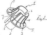
図1および図2には、本発明の好ましい実施形態によるリリースクリップ1が示されている。リリースクリップ1はリリースボディ(解放本体)2を有し、該リリースボディ2は薄壁であり、かつ上記説明および特許請求の範囲の記載に示された長さ、すなわち、少なくともコネクタの開口からグリッパリング(図3に示す)までの距離に等しい長さを有している。
In the accompanying drawings, several preferred embodiments of a release clip according to the present invention are shown.
1 and 2 show a
また、リリースクリップは、この長手方向の割れ目部(split/スプリット)5を有し、該割れ目部5には、クリップの両側が、特に薄壁領域においてオーバーラップすることを防止する溝−舌形状7、8が形成されている。
The release clip also has this
リリースクリップ1はまたフランジ3を有しており、該フランジ3は、リリースボディ2の頂部に湾曲遷移部を有している。フランジ3およびリリースクリップ1には更に、リリースクリップ1を用いるときに、より良いグリップを付与する摩擦を生じさせる隆起部4を備えたグリップ面が設けられている。解放すべきチューブの周囲に取付けられるように、ヒンジ効果を生じさせ、従ってリリースクリップ1を開くことができるようにするため、フランジ3にはまた、凹部9と、長手方向割れ目部5とは反対側のカットアウト(切り出し部)6とが設けられている。フランジ3は、2つの別個の部分(セクション)3′、3″を形成している。
The
また、図3には、本発明によるリリースクリップ1が、チューブ10とともにチューブコネクタ11内に押込まれているところが示されている。図3に示すように、チューブコネクタ11は、該コネクタ11の開口近くのシーリングリング12と、ロッキングリング13を備えた内側円錐部分15とを有している。ロッキングリング13は割れ目部しており、このため、円錐部分15に沿って、コネクタ11(およびチューブ10)の長手方向に移動できる。図3では、円錐部分15は、チューブコネクタ1内のインサート14に設けられているところが示されている。これはコネクタの一例であり、本発明はこの例とは独立している。なぜならば、円錐部分15は、コネクタ本体内のインサートに設けることもできるし、コネクタ本体の一部としてコネクタ本体に一体的に設けることもできるからである。
FIG. 3 also shows the
図3には、薄壁のリリースボディ2を備えたリリースクリップ1が示されている。リリースクリップ1は、長手方向割れ目部(図1および図2)を拡大してチューブ10上に押込むことによりチューブ10の周囲に取付けられる。リリースボディ2は、上方のシーリングリンク12を通ってチューブコネクタ11内に押込まれ、更にグリッパリング13に当接するまで押込まれる。図3に示すように、グリッパリング13は、好ましくはその内周面に沿って円錐面16を有している。リリースクリップのリリースボディ2はこの円錐面16に接触し、次に、グリッパリング13をコネクタ内で押込む。グリッパリング13は割れ目部しているので、グリッパリングがチューブコネクタ11の円錐部分15に沿って移動すると、グリッパリングは拡大する。また、リリースボディ2は、グリッパリング13の内側円錐面16に沿って移動することにより、グリッパリング13を押拡げる。
FIG. 3 shows a
リリースクリップ1がグリッピングリング13を押込んでグリッピングリングを拡大させると、グリッピングリング13はチューブ10の周囲のグリップを解放し、チューブ10を引出すことができるようにする。これにより、リリースクリップ1も引出すことができ、チューブ10はチューブコネクタ11から解放される。
When the
図4から図7には本発明の他の実施形態が示されており、また、幾つかの付加特徴を有する上記リリースクリップが示されている。
図4から図7に示すように、フランジ3の一方の別個の部分(セクション)3′には端セクション突出部(端部分突出部)20が形成されており、該端セクション突出部20は、他方の別個の部分(セクション)3″の端セクション(端部分)に形成されたカットアウトセクション(切り出し部分)22により受入れられるようになっている。これは、使用時に、両フランジセクション(フランジ部分)3′、3″がヒンジ9の回りで旋回運動すると、端セクション突出部20がカットアウト22により受入れられる構成である。別個セクション3′の他端には、壁セクション26に配置された隆起ニブ24が形成されている。壁セクション26は、フランジセクション3′の縁部からほぼ半径方向外方に延びている。ニブ24は、壁セクション26に沿って、ほぼ長手方向に延びている。フランジ3のセクション3″には、チャネル30が形成された対応壁セクション28が形成されている。チャネル30は、クリップ1が管状要素の周囲で閉じられかつクリップ1がコネクタ11内に挿入されると、ニブ24を受け入れるようになっている。
FIGS. 4 to 7 show another embodiment of the present invention and the release clip having several additional features.
As shown in FIGS. 4 to 7, an end section protrusion (end portion protrusion) 20 is formed on one separate portion (section) 3 ′ of the
両セクション3′、3″をヒンジ9の回りで旋回運動させることによりクリップ1が開かれると、端セクション突出部20がカットアウト22により受入れられる。端セクション突出部20がカットアウト22の方向に移動する結果として、使用者は、リリースクリップ1が管状要素上に正しくなく配置されてしまうことを防止できる。なぜならば、フランジ3の両個別フランジ3′、3″間の可視ギャップ32がほぼ縮小されるからである。端セクション突出部20がカットアウト22により受入れられる結果として、クリップ1の安定性が増大される。クリップ1がヒンジ9の回りで旋回運動されるとき、端セクション突出部20の上面21は、カットアウトセクション22の下面42と摺動接触することができる。突出部20の形状は、カットアウト22の形状に一致させることができる。突出部20がカットアウト22により受入れられる結果として、クリップ1にはストップ機能および安定化機能が付与される。
When the
ヒンジ9の回りで両セクション3′、3″を旋回運動させることにより、クリップ1が管状要素10の回りで閉じられかつリリースクリップ1がコネクタ11内に挿入されるとき、ニブ24がチャネル30に向かって移動しかつ該チャネル30により受入れられる。クリップ1のニブ24がチャネル30により受入れられる結果として、クリップ1にはストップ機能および安定化機能が付与される。
By pivoting both
クリップ1はまた、ヒンジ9の両側に配置された1対のウェブ34、36を有している。これらのウェブは、クリップ1の割れ目部5を開くことを補助するのに使用される。両ウェブ34、36は、フランジ3から長手方向に延びているレバーとして機能する。両ウェブ34、36が、矢印40で示すように互いに近付く方向に押されると、割れ目部5が開かれる。両ウェブ34、36が解放されると、両ウェブは矢印40とは逆方向に自動的に移動し、割れ目部5のサイズは小さくなる。
The
Claims (16)
前記管状本体は、前記管状本体の周りで円周方向に延びるフランジと、前記管状本体の一領域により形成された一体ヒンジとを有し、前記リリースクリップは、管状要素へのスナップ取付けおよび管状要素からのスナップ取外しが可能であり、
前記リリースクリップは、前記リリースクリップの前記割れ目部を開くのに使用できる1対のウェブを有し、それぞれのウェブは前記一体ヒンジの両側に配置され、
前記ウェブは、前記フランジから長手方向に延びる、且つ、前記ウェブがともに近づく方向に押される場合に前記管状本体を前記割れ目部を開くように前記ヒンジを中心に開かせる、レバーとして作動することを特徴とするリリースクリップ。A release clip capable of releasing an end of a tubular element from being secured in a connector element, the release clip comprising a tubular body, the tubular body being at a longitudinal axis of the tubular body A crack extending along the
The tubular body has a flange extending circumferentially around the tubular body and an integral hinge formed by a region of the tubular body , the release clip being snap-attached to the tubular element and the tubular element Snap removal from is possible,
The release clip has a pair of webs that can be used to open the split portion of the release clip, each web being disposed on either side of the integral hinge ,
The web operates as a lever that extends longitudinally from the flange and causes the tubular body to open about the hinge so as to open the crack when the web is pushed together. A featured release clip.
Applications Claiming Priority (3)
| Application Number | Priority Date | Filing Date | Title |
|---|---|---|---|
| NO20051920 | 2005-04-20 | ||
| NO20051920A NO20051920L (en) | 2005-04-20 | 2005-04-20 | Utloserklips. |
| PCT/NO2006/000145 WO2006112727A1 (en) | 2005-04-20 | 2006-04-20 | Release clip |
Publications (3)
| Publication Number | Publication Date |
|---|---|
| JP2008537081A JP2008537081A (en) | 2008-09-11 |
| JP2008537081A5 JP2008537081A5 (en) | 2011-08-04 |
| JP5107233B2 true JP5107233B2 (en) | 2012-12-26 |
Family
ID=35267074
Family Applications (1)
| Application Number | Title | Priority Date | Filing Date |
|---|---|---|---|
| JP2008507583A Expired - Fee Related JP5107233B2 (en) | 2005-04-20 | 2006-04-20 | Release clip |
Country Status (10)
| Country | Link |
|---|---|
| US (1) | US9845906B2 (en) |
| EP (1) | EP1872046B1 (en) |
| JP (1) | JP5107233B2 (en) |
| KR (1) | KR101296171B1 (en) |
| CN (1) | CN101203706B (en) |
| AT (1) | ATE471481T1 (en) |
| DE (1) | DE602006014954D1 (en) |
| ES (1) | ES2347276T3 (en) |
| NO (1) | NO20051920L (en) |
| WO (1) | WO2006112727A1 (en) |
Families Citing this family (5)
| Publication number | Priority date | Publication date | Assignee | Title |
|---|---|---|---|---|
| US8695180B2 (en) | 2011-01-06 | 2014-04-15 | Dean Delle Donne | Locking clip and system |
| USD732359S1 (en) | 2012-08-21 | 2015-06-23 | Orbit Irrigation Products, Inc. | Conduit removal tool |
| US11215769B2 (en) | 2019-03-07 | 2022-01-04 | Mellanox Technologies, Ltd. | MPO locking |
| US20220266430A1 (en) * | 2021-02-24 | 2022-08-25 | Richard Warren | Removal Tool for Push-to-Connect Fittings |
| PL4177506T3 (en) | 2021-11-03 | 2024-02-26 | Ka Group Ag | Push-in tube connector port |
Family Cites Families (14)
| Publication number | Priority date | Publication date | Assignee | Title |
|---|---|---|---|---|
| DE2547411B2 (en) * | 1975-10-23 | 1978-04-27 | Armaturenfabrik Hermann Voss, 5290 Wipperfuerth | Hose and / or pipe coupling |
| US4927185A (en) * | 1989-03-07 | 1990-05-22 | Huron Products Corporation | Release tool for fluid quick connectors |
| US5084954A (en) * | 1990-12-19 | 1992-02-04 | Itt Corporation | Quick connector universal release tool |
| US5226230A (en) * | 1991-12-13 | 1993-07-13 | Itt Corporation | Universal o.d. release tool |
| US5301408A (en) * | 1992-03-31 | 1994-04-12 | R & B, Inc. | Garter spring coupling release tool |
| US5328215A (en) * | 1992-09-14 | 1994-07-12 | Rovac Corporation | Pipe joint assembly |
| US5533761A (en) * | 1994-10-26 | 1996-07-09 | Itt Corporation | Quick connector release member |
| FR2788581B1 (en) * | 1999-01-15 | 2001-02-23 | Legris Sa | CONNECTION ASSEMBLY OF A CONDUIT END TO AN ELEMENT |
| US6343814B1 (en) * | 1999-11-08 | 2002-02-05 | Ti Group Automotive Systems, Llc | Insertion verifier dust cap |
| US6557903B2 (en) * | 2000-12-27 | 2003-05-06 | Itt Manufacturing Enterprises, Inc. | Twist lock high pressure quick connector |
| US7316428B2 (en) * | 2002-10-07 | 2008-01-08 | Tokai Rubber Industries, Ltd. | Connection verifying device and connection verifying structure for a pipe and a connector |
| GB0411099D0 (en) * | 2004-05-19 | 2004-06-23 | Oystertec Plc | Pipe fitting |
| US7350282B2 (en) * | 2004-08-27 | 2008-04-01 | Lisle Corporation | Tool for disconnection of tubing from a coupling |
| US7338093B2 (en) * | 2004-09-03 | 2008-03-04 | Voss Automotive Gmbh | Connection for fluid lines |
-
2005
- 2005-04-20 NO NO20051920A patent/NO20051920L/en not_active Application Discontinuation
-
2006
- 2006-04-20 WO PCT/NO2006/000145 patent/WO2006112727A1/en active Application Filing
- 2006-04-20 AT AT06733116T patent/ATE471481T1/en not_active IP Right Cessation
- 2006-04-20 JP JP2008507583A patent/JP5107233B2/en not_active Expired - Fee Related
- 2006-04-20 EP EP06733116A patent/EP1872046B1/en not_active Not-in-force
- 2006-04-20 US US11/912,181 patent/US9845906B2/en active Active
- 2006-04-20 KR KR1020077026954A patent/KR101296171B1/en active IP Right Grant
- 2006-04-20 ES ES06733116T patent/ES2347276T3/en active Active
- 2006-04-20 CN CN2006800222388A patent/CN101203706B/en not_active Expired - Fee Related
- 2006-04-20 DE DE602006014954T patent/DE602006014954D1/en active Active
Also Published As
| Publication number | Publication date |
|---|---|
| EP1872046B1 (en) | 2010-06-16 |
| KR20080008368A (en) | 2008-01-23 |
| US20080309079A1 (en) | 2008-12-18 |
| WO2006112727A1 (en) | 2006-10-26 |
| ES2347276T3 (en) | 2010-10-27 |
| ATE471481T1 (en) | 2010-07-15 |
| CN101203706A (en) | 2008-06-18 |
| JP2008537081A (en) | 2008-09-11 |
| NO20051920D0 (en) | 2005-04-20 |
| DE602006014954D1 (en) | 2010-07-29 |
| KR101296171B1 (en) | 2013-08-13 |
| US9845906B2 (en) | 2017-12-19 |
| NO20051920L (en) | 2006-10-23 |
| CN101203706B (en) | 2010-05-26 |
| EP1872046A1 (en) | 2008-01-02 |
Similar Documents
| Publication | Publication Date | Title |
|---|---|---|
| US9556990B2 (en) | Connection device for medium conduits | |
| JP3798791B2 (en) | Removable plug-in coupling with protective sleeve | |
| KR101001230B1 (en) | Fluid line coupling | |
| US7163238B1 (en) | Connector for flexible and semi-rigid pipings | |
| JP5107233B2 (en) | Release clip | |
| JP4791532B2 (en) | Quick coupler with insertion fixing | |
| JP3988118B2 (en) | Release sleeve and coupling assembly using the release sleeve | |
| US6334634B1 (en) | Push-to-connect tubing fitting | |
| JP2006010010A (en) | Pipe joint | |
| JPH05231579A (en) | Removable insert connector for simi-hard pipe | |
| JPH07151278A (en) | Joint for corrugated pipe | |
| US20100213702A1 (en) | Release tool for quick connector | |
| JP2006322615A (en) | Plug type joint | |
| JP5158614B2 (en) | Pipe fitting | |
| TW200907209A (en) | A coupling device for a fluid line | |
| JPS61248993A (en) | Fluid duct fixture assembly | |
| KR100958816B1 (en) | Pipe joint | |
| JP2592358B2 (en) | Pipe fittings | |
| JP2003021287A (en) | Spigot joint | |
| JPH04211792A (en) | Coupling device for fluid power line | |
| JP3988181B2 (en) | Tube fitting | |
| JP3747309B2 (en) | Pipe fitting | |
| WO2007019270A2 (en) | Connector for flexible and semi-rigid pipings | |
| JP4101057B2 (en) | Method for fixing flexible member in tube with tight fit and assembly used in the method | |
| JPH0139995Y2 (en) |
Legal Events
| Date | Code | Title | Description |
|---|---|---|---|
| A621 | Written request for application examination |
Free format text: JAPANESE INTERMEDIATE CODE: A621 Effective date: 20090203 |
|
| A521 | Request for written amendment filed |
Free format text: JAPANESE INTERMEDIATE CODE: A523 Effective date: 20100607 |
|
| A521 | Request for written amendment filed |
Free format text: JAPANESE INTERMEDIATE CODE: A523 Effective date: 20110617 |
|
| A977 | Report on retrieval |
Free format text: JAPANESE INTERMEDIATE CODE: A971007 Effective date: 20111025 |
|
| A131 | Notification of reasons for refusal |
Free format text: JAPANESE INTERMEDIATE CODE: A131 Effective date: 20111031 |
|
| A601 | Written request for extension of time |
Free format text: JAPANESE INTERMEDIATE CODE: A601 Effective date: 20120131 |
|
| A602 | Written permission of extension of time |
Free format text: JAPANESE INTERMEDIATE CODE: A602 Effective date: 20120207 |
|
| A601 | Written request for extension of time |
Free format text: JAPANESE INTERMEDIATE CODE: A601 Effective date: 20120229 |
|
| A602 | Written permission of extension of time |
Free format text: JAPANESE INTERMEDIATE CODE: A602 Effective date: 20120307 |
|
| A521 | Request for written amendment filed |
Free format text: JAPANESE INTERMEDIATE CODE: A523 Effective date: 20120329 |
|
| TRDD | Decision of grant or rejection written | ||
| A01 | Written decision to grant a patent or to grant a registration (utility model) |
Free format text: JAPANESE INTERMEDIATE CODE: A01 Effective date: 20120924 |
|
| A01 | Written decision to grant a patent or to grant a registration (utility model) |
Free format text: JAPANESE INTERMEDIATE CODE: A01 |
|
| A61 | First payment of annual fees (during grant procedure) |
Free format text: JAPANESE INTERMEDIATE CODE: A61 Effective date: 20121003 |
|
| R150 | Certificate of patent or registration of utility model |
Ref document number: 5107233 Country of ref document: JP Free format text: JAPANESE INTERMEDIATE CODE: R150 Free format text: JAPANESE INTERMEDIATE CODE: R150 |
|
| FPAY | Renewal fee payment (event date is renewal date of database) |
Free format text: PAYMENT UNTIL: 20151012 Year of fee payment: 3 |
|
| R250 | Receipt of annual fees |
Free format text: JAPANESE INTERMEDIATE CODE: R250 |
|
| R250 | Receipt of annual fees |
Free format text: JAPANESE INTERMEDIATE CODE: R250 |
|
| R250 | Receipt of annual fees |
Free format text: JAPANESE INTERMEDIATE CODE: R250 |
|
| R250 | Receipt of annual fees |
Free format text: JAPANESE INTERMEDIATE CODE: R250 |
|
| R250 | Receipt of annual fees |
Free format text: JAPANESE INTERMEDIATE CODE: R250 |
|
| R250 | Receipt of annual fees |
Free format text: JAPANESE INTERMEDIATE CODE: R250 |
|
| R250 | Receipt of annual fees |
Free format text: JAPANESE INTERMEDIATE CODE: R250 |
|
| LAPS | Cancellation because of no payment of annual fees |