JP5106552B2 - Paper transport roller, paper transport device, and paper transport method - Google Patents
Paper transport roller, paper transport device, and paper transport method Download PDFInfo
- Publication number
- JP5106552B2 JP5106552B2 JP2010026475A JP2010026475A JP5106552B2 JP 5106552 B2 JP5106552 B2 JP 5106552B2 JP 2010026475 A JP2010026475 A JP 2010026475A JP 2010026475 A JP2010026475 A JP 2010026475A JP 5106552 B2 JP5106552 B2 JP 5106552B2
- Authority
- JP
- Japan
- Prior art keywords
- roller
- diameter
- paper
- rollers
- types
- Prior art date
- Legal status (The legal status is an assumption and is not a legal conclusion. Google has not performed a legal analysis and makes no representation as to the accuracy of the status listed.)
- Expired - Fee Related
Links
- 238000000034 method Methods 0.000 title claims description 6
- 238000003825 pressing Methods 0.000 claims description 4
- 230000032258 transport Effects 0.000 description 36
- 239000000428 dust Substances 0.000 description 5
- 230000006866 deterioration Effects 0.000 description 2
- 230000000694 effects Effects 0.000 description 2
- 238000004519 manufacturing process Methods 0.000 description 2
- 238000009825 accumulation Methods 0.000 description 1
- 230000000994 depressogenic effect Effects 0.000 description 1
Images


Landscapes
- Delivering By Means Of Belts And Rollers (AREA)
- Registering, Tensioning, Guiding Webs, And Rollers Therefor (AREA)
- Sheets, Magazines, And Separation Thereof (AREA)
Description
本発明は、画像形成装置に備えられる用紙搬送ローラ、用紙搬送装置および用紙搬送方法に関する。 The present invention relates to a sheet conveying roller, a sheet conveying apparatus, and a sheet conveying method provided in an image forming apparatus.
一般的に、複写機、プリンタ、ファクシミリ、または、これらの複合機等の画像形成装置には、用紙を搬送する用紙搬送装置が備えられる。用紙搬送装置は、回転して用紙に摩擦係合することにより用紙を搬送する用紙搬送ローラを有している。 In general, an image forming apparatus such as a copying machine, a printer, a facsimile machine, or a multifunction machine of these is provided with a paper transport device for transporting paper. The sheet conveying device has a sheet conveying roller that conveys a sheet by rotating and frictionally engaging the sheet.
しかしながら、このような用紙搬送ローラは、表面に用紙の紙粉が堆積することにより用紙に摩擦係合しにくくなり、搬送不良や紙詰まり等を引き起こすという問題があった。 However, such a paper transport roller has a problem that it is difficult to frictionally engage the paper due to the accumulation of paper dust on the surface, resulting in a transport failure or a paper jam.
このような問題を解決する用紙搬送ローラとして、中央に軸孔と、平歯車の歯状としたローラ表面と、少なくとも一側面中央にボス部とを有する任意の数の単位ローラを備え、各単位ローラを近接させて軸孔に支持軸を貫挿したものがある(例えば、特許文献1参照)。 As a paper conveying roller that solves such problems, an arbitrary number of unit rollers having a shaft hole at the center, a roller surface having a spur gear tooth shape, and a boss portion at least in the center of one side surface are provided. There is one in which a support shaft is inserted into a shaft hole with a roller in proximity (see, for example, Patent Document 1).
特許文献1に記載された用紙搬送ローラは、ボス部により単位ローラ間に隙間を形成する。これにより、特許文献1に記載された用紙搬送ローラは、用紙の紙粉を隙間に排除して紙粉がローラ表面へ堆積することを防止していた。 The paper conveyance roller described in Patent Document 1 forms a gap between unit rollers by a boss portion. As a result, the paper transport roller described in Patent Document 1 has prevented paper dust from accumulating on the roller surface by removing paper dust from the paper in the gap.
しかしながら、用紙には、破断面が均一でなく多くの紙粉を発生させる粗悪なものがある。特許文献1に記載された用紙搬送ローラは、そのような用紙を頻繁に搬送すると、破断面や紙粉によって表面の凹凸部が摩耗し、搬送不良や紙詰まり等を起こして搬送性能を低下させるという課題があった。 However, some papers have a rough surface that does not have a uniform fracture surface and generates a large amount of paper dust. When the paper conveyance roller described in Patent Document 1 frequently conveys such paper, the surface irregularities are worn by a fracture surface or paper dust, resulting in poor conveyance or paper jam, and lowering the conveyance performance. There was a problem.
本発明は、上述の課題を解決するためになされたもので、表面の凹凸部の摩耗による搬送性能の低下をより長期間防止することができる用紙搬送ローラを提供することを目的とする。 The present invention has been made to solve the above-described problems, and an object of the present invention is to provide a paper transport roller that can prevent a decrease in transport performance due to wear of the uneven portions on the surface for a longer period of time.
本発明の用紙搬送ローラは、径の異なるN(Nは2以上の整数)種類のローラを備え、前記N種類のローラは用紙の搬送方向と略直交する同一の回転軸線廻りに回転可能に配置され、前記N種類のローラの表面には凹凸部がそれぞれ形成され、前記N種類のローラのうちi+1(iは1からN−1までの整数)番目に径の大きいローラ表面の凹凸部は、i番目に径の大きいローラ表面の凹部の径より大きい径を有する凸部と、該凸部より陥没した凹部によって構成され、前記i番目に径の大きいローラ表面が有する凹凸部の摩耗により、前記i番目に径の大きいローラ表面の凹部の径より大きい径を有する凸部と、該凸部より陥没した凹部とによって構成される凹凸部が表面に形成されるi+1番目に径の大きいローラが最大径となるのに応じて、該i+1番目に径の大きいローラによって前記用紙を搬送する。 The paper transport roller of the present invention includes N (N is an integer of 2 or more) types of rollers having different diameters, and the N types of rollers are arranged so as to be rotatable about the same rotation axis substantially orthogonal to the paper transport direction. An uneven portion is formed on the surface of each of the N types of rollers, and the uneven portion on the surface of the roller having the largest diameter i + 1 (i is an integer from 1 to N-1) among the N types of rollers is a convex portion having a larger diameter than the diameter of the recess of the i-th to the diameter of the large roller surface, is constituted by a recess that is recessed from the convex portions, the wear of the concave-convex portion having a large roller surface diameter to the i-th has the The i + 1th largest roller is the largest, with a concavo-convex part formed by a convex part having a diameter larger than the diameter of the concave part on the surface of the i-th largest roller and a concave part recessed from the convex part. As the diameter becomes Te, it conveys the sheet by a large roller diameter to the i + 1 th.
また、本発明の用紙搬送装置は、上記構成を有する用紙搬送ローラと、前記N種類のローラのうちi番目に径の大きいローラに前記用紙を圧接させ、前記i番目に径の大きいローラ表面の凹凸部が摩耗すると、前記i+1番目に径の大きいローラに前記用紙を圧接させる圧接手段とを備える。 The sheet conveying apparatus of the present invention, a sheet conveying roller having the above structure, the is pressed against the paper i largest roller diameter among the N types of rollers, a large roller surface diameter to the i-th When uneven portion is worn, and a pressing means for pressing the paper into a large roller diameter to the (i + 1) th.
また、本発明の用紙搬送方法は、用紙の搬送方向と略直交する同一の回転軸線廻りに回転可能に配置され、表面に凹凸部が形成された径の異なるN種類のローラのうちi(iは1からN−1までの整数)番目に径の大きいローラによって前記用紙を搬送し、i番目に径の大きいローラ表面の凹凸部が摩耗すると、i番目に径の大きいローラ表面の凹部の径より大きい径を有する凸部と、該凸部より陥没した凹部とによって構成される凹凸部が表面に形成されたi+1番目に径の大きいローラによって前記用紙を搬送する。 Further, the sheet conveying method of the present invention is arranged to rotate around the same rotation axis substantially orthogonal to the sheet conveying direction, and i (i) among N types of rollers having different diameters having irregularities formed on the surface. Is an integer from 1 to N-1) When the paper is conveyed by the roller having the largest diameter, and the uneven portion on the surface of the i-th largest roller wears, the diameter of the recess on the surface of the i-th largest roller The sheet is conveyed by a roller having an i + 1th largest diameter formed on the surface with a concavo-convex portion formed by a convex portion having a larger diameter and a concave portion recessed from the convex portion.
本発明は、表面の凹凸部の摩耗による搬送性能の低下をより長期間防止する用紙搬送ローラを提供することができる。 The present invention can provide a paper transport roller that prevents a decrease in transport performance due to wear on the surface irregularities for a longer period of time.
次に、本発明の第1の実施の形態について図面を参照して詳細に説明する。 Next, a first embodiment of the present invention will be described in detail with reference to the drawings.
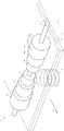
本発明の第1の実施の形態としての用紙搬送装置1の外観図を図1に示す。用紙搬送装置1は、画像形成装置に備えられ、画像形成装置によって処理される用紙を搬送する。 FIG. 1 shows an external view of a sheet conveying apparatus 1 as a first embodiment of the present invention. The paper transport apparatus 1 is provided in the image forming apparatus and transports paper to be processed by the image forming apparatus.
なお、本発明の第1の実施の形態では、本発明の用紙搬送装置を、画像形成装置に備えられた用紙載置台に載置された用紙を1枚ずつピックアップして画像形成部に向けて搬送する給紙装置として構成した例について説明する。 In the first embodiment of the present invention, the sheet conveying device of the present invention picks up the sheets placed on the sheet placing table provided in the image forming apparatus one by one and faces the image forming unit. An example configured as a sheet feeding device to be conveyed will be described.
図1において、用紙搬送装置1は、用紙搬送ローラ2と、用紙7が載置される用紙載置台3と、付勢部材4とを備えている。また、用紙搬送ローラ2は、複数のローラ5a、5bおよび5c(以下、総称してローラ5ともいう)を一対ずつと、ローラシャフト6とを備えている。
In FIG. 1, the paper transport apparatus 1 includes a
なお、図1において、3種類の異なる径を持つローラ5を2つずつ示しているが、本発明の用紙搬送ローラが備えるローラの数および同一径のローラの数を限定するものではない。 In FIG. 1, two rollers 5 having three different diameters are shown, but the number of rollers and the number of rollers having the same diameter provided in the paper transport roller of the present invention are not limited.
付勢部材4は、用紙載置台3を用紙搬送ローラ2方向に押圧し、用紙載置台3に載置された用紙7の上面をローラ5a、5bおよび5cのいずれかに圧接させる。なお、用紙載置台3および付勢部材4は、本発明における圧接手段の一実施形態を構成する。
The urging member 4 presses the sheet placing table 3 in the direction of the
ローラシャフト6は、用紙7の搬送方向Bに対して略直交して配置され、回転方向Aの向きに回転可能に構成されている。
The
ローラ5は中央に軸孔を有し、軸孔に挿入されたローラシャフト6に取り付けられている。ローラ5は、ローラシャフト6を回転軸としてローラシャフト6と一体に回転可能である。ローラ5は回転方向Aの向きに回転することにより、用紙7を搬送方向Bの向きに搬送する。
The roller 5 has a shaft hole at the center, and is attached to a
図2に、用紙搬送ローラ2の正面図を示す。
FIG. 2 shows a front view of the
図2に示すように、ローラ5aの径aは、ローラ5bの径bより大きく、ローラ5bの径bはローラ5cの径cより大きい。このように、ローラ5は、ローラシャフト6の両端から径の大きい順(ローラ5a、5b、5cの順)に対称に配置されている。
As shown in FIG. 2, the diameter a of the
図3を用いて、ローラ5の表面に形成された凹凸について説明する。 The unevenness formed on the surface of the roller 5 will be described with reference to FIG.
図3において、ローラ5bの凸部51bの径は、ローラ5bより大きな径を持つローラ5aの凹部52aの径より大きくなっている。
In FIG. 3, the diameter of the
また、ローラ5bの凸部51bの径は、ローラ5aの凸部51aの径より小さくなっている。
Moreover, the diameter of the
また、ローラ5cの凸部51cの径は、ローラ5cより大きな径を持つローラ5bの凹部52bの径より大きくなっている。
Further, the diameter of the
また、ローラ5cの凸部51cの径は、ローラ5bの凸部51bの径より小さくなっている。
Moreover, the diameter of the
次に、用紙搬送装置1の動作について説明する。 Next, the operation of the sheet conveying apparatus 1 will be described.
用紙搬送装置1は、まず、付勢部材4によって用紙載置台3に載置された用紙7の上面をローラ5aに圧接させ、ローラシャフト6を回転させ、ローラ5aを用紙に摩擦係合させて用紙を搬送する。ローラ5aの凸部51aは、搬送枚数に応じて摩耗していく。ローラ5aの凸部51aの高さがローラ5bの凸部51bと同じ高さになるまで摩耗すると、ローラ5aは用紙7に摩擦係合しにくくなる。このような状態になると、用紙搬送装置1は、付勢部材4および用紙載置台3によって用紙7をローラ5bに圧接させ、ローラシャフト6を回転させ、ローラ5bを用紙7に摩擦係合させることにより、用紙を搬送する。
First, the sheet conveying apparatus 1 presses the upper surface of the sheet 7 placed on the sheet placing table 3 by the urging member 4 against the
同様に、ローラ5bの凸部51bの高さがローラ5cの凸部51cと同じ高さになるまで摩耗すると、用紙搬送装置1は、ローラ5cを用紙7に摩擦係合させることにより、用紙7を搬送する。
Similarly, when the
次に、本発明の第1の実施の形態の効果について説明する。 Next, effects of the first exemplary embodiment of the present invention will be described.
本発明の第1の実施の形態としての用紙搬送ローラおよびこれを備えた用紙搬送装置は、表面の凹凸部の摩耗による搬送性能の低下をより長期間防止することができる。 The sheet conveying roller and the sheet conveying apparatus including the sheet conveying roller according to the first embodiment of the present invention can prevent a decrease in conveying performance due to wear of the uneven portions on the surface for a longer period.
その理由は、径の異なるN種類のローラにより、まず径の大きなローラが用紙に摩擦係合して用紙を搬送する。そして、用紙を搬送していたローラ表面の凹凸部が摩耗すると、次に径の大きなローラが、摩耗していない凹凸部によって用紙を搬送するからである。 The reason is that, with N types of rollers having different diameters, a roller having a large diameter first frictionally engages the paper and conveys the paper. Then, when the uneven portion on the surface of the roller that has conveyed the paper is worn, the next roller having the largest diameter conveys the paper by the uneven portion that is not worn.
また、本発明の第1の実施の形態としての用紙搬送ローラおよび用紙搬送装置は、一部のローラが摩耗して機能しなくなる前に他のローラを確実に機能させることができる。 In addition, the paper transport roller and the paper transport device according to the first embodiment of the present invention can make other rollers function reliably before some of the rollers become worn and do not function.
その理由は、各ローラの凸部までの径を、より大きな径を有するローラの凹部の径より大きくなるよう凹凸部を形成するため、各ローラ表面の凸部が凹部まで摩耗する前に、次に大きな径を持つローラの凹凸部を用紙に摩擦係合させるからである。 The reason for this is that the concave and convex portions are formed so that the diameter to the convex portion of each roller is larger than the diameter of the concave portion of the roller having a larger diameter. This is because the uneven portion of the roller having a large diameter is frictionally engaged with the paper.
また、本発明の第1の実施の形態としての用紙搬送ローラおよび用紙搬送装置は、径の異なるN種類のローラをより安定して回転させることができる。 In addition, the sheet conveying roller and the sheet conveying apparatus according to the first embodiment of the present invention can more stably rotate N types of rollers having different diameters.
その理由は、同一の径を持つ一対ずつのローラを回転軸線方向に対称に配置するからである。 This is because a pair of rollers having the same diameter are arranged symmetrically in the rotation axis direction.
また、本発明の第1の実施の形態としての用紙搬送ローラおよび用紙搬送装置は、径の異なるN種類のローラをさらに安定して回転させることができる。 In addition, the sheet conveying roller and the sheet conveying apparatus according to the first embodiment of the present invention can further stably rotate N types of rollers having different diameters.
その理由は、同一の径を持つ一対ずつのローラを回転軸線方向の両端から径の大きい順に配置するからである。 The reason is that a pair of rollers having the same diameter are arranged in descending order from both ends in the rotation axis direction.
なお、本発明の第1の実施の形態において、用紙搬送装置1および用紙搬送ローラ2を給紙装置および給紙ローラとして構成する例について説明したが、本発明の用紙搬送装置および用紙搬送ローラは、給紙装置および給紙ローラに限らず、画像形成装置において用紙を搬送する用紙搬送装置および用紙搬送ローラ全般に適用可能である。例えば、本発明の用紙搬送ローラは、画像形成部の排紙口から用紙を排紙する方向に搬送する排紙装置および排紙ローラとして構成されていてもよい。
In the first embodiment of the present invention, the example in which the sheet conveying device 1 and the
次に、本発明の第2の実施の形態について図面を参照して説明する。本発明の第2の実施の形態としての用紙搬送装置8は、本発明の第1の実施の形態としての用紙搬送装置1に対して、用紙搬送ローラ2に替えて用紙搬送ローラ9を備える点が異なる。その他の構成については本発明の第1の実施の形態としての用紙搬送装置1と同一のため、図示および説明を省略する。
Next, a second embodiment of the present invention will be described with reference to the drawings. The sheet conveying apparatus 8 as the second embodiment of the present invention is provided with a sheet conveying roller 9 instead of the
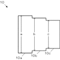
図4に、本発明の第2の実施の形態としての用紙搬送ローラ9の正面図を示す。 FIG. 4 shows a front view of a sheet conveying roller 9 as a second embodiment of the present invention.
用紙搬送ローラ9は、ローラ10と、本発明の第1の実施の形態と同一のローラシャフト6とを有している。
The paper transport roller 9 includes a
なお、図4には、2つのローラ10を示しているが、本発明の用紙搬送ローラが備えるローラの数を限定するものではない。
In FIG. 4, two
ローラ10は、異なる径を有する複数のローラが一体に形成されたものである。ローラ10は、回転径の大きい方が外側になるよう、回転軸線方向に対称にローラシャフト6に取り付けられている。
The
ローラ10の正面図を図5に示し、側面図を図6に示す。ローラ10は、径aを有する部分10a、径bを有する部分10b、および径cを有する部分10cを有している。ここで、径aは径bより大きく、径bは径cより大きくなっている。
A front view of the
ローラ10の表面には、図3に示した本発明の第1の実施の形態としてのローラ5と同様の凹凸部が形成されている。すなわち、ローラ部分10aの表面には凸部51aおよび凹部52aを有する凹凸部が形成される。また、ローラ部分10bの表面には凸部51bおよび凹部52bを有する凹凸部が形成される。また、ローラ部分10cの表面には凸部51cおよび凹部52cを有する凹凸部が形成される。
On the surface of the
以上のように構成された用紙搬送装置8は、本発明の第1の実施の形態としての用紙搬送装置1と同様に動作する。 The sheet conveying apparatus 8 configured as described above operates in the same manner as the sheet conveying apparatus 1 as the first embodiment of the present invention.
次に、本発明の第2の実施の形態の用紙搬送ローラおよびこの用紙搬送ローラを備えた用紙搬送装置の効果について述べる。 Next, the effects of the sheet conveying roller and the sheet conveying apparatus including the sheet conveying roller according to the second embodiment of the present invention will be described.
本発明の第2の実施の形態としての用紙搬送ローラおよび用紙搬送装置は、表面の凹凸部の摩耗による搬送性能の低下をより長期間防止することができる用紙搬送ローラの製造コストおよび管理コストを減らすことができる。 The sheet conveying roller and the sheet conveying apparatus according to the second embodiment of the present invention can reduce the manufacturing cost and the management cost of the sheet conveying roller that can prevent the deterioration of the conveying performance due to wear of the uneven portion on the surface for a longer period of time. Can be reduced.
その理由は、径の異なるN種類のローラの少なくとも一部を一体に形成したので、製造過程における組立を簡易にし、保守管理対象の部品点数を減らすことができるからである。 The reason is that at least a part of the N types of rollers having different diameters are integrally formed, so that assembly in the manufacturing process can be simplified and the number of parts to be maintained can be reduced.
次に、本発明の用紙搬送ローラおよび用紙搬送装置を最小構成で実施する形態について説明する。 Next, an embodiment in which the sheet conveying roller and the sheet conveying apparatus of the present invention are implemented with a minimum configuration will be described.
図1に示した用紙搬送装置1は、用紙搬送ローラ2と、用紙載置台3および付勢部材4によって構成される圧接部を少なくとも備える。
The sheet conveying apparatus 1 shown in FIG. 1 includes at least a
用紙搬送ローラ2は、径の異なるN種類のローラ5を少なくとも備え、各ローラ5の表面には凹凸部がそれぞれ形成される。
The
また、ローラ5のうちi+1(iは1からN−1までの整数)番目に径の大きいローラ表面の凹凸部は、i番目に径の大きいローラ表面の凹部の径より大きい径を有する凸部と、該凸部より陥没した凹部とによって構成される。 Further, the uneven portion on the surface of the roller 5 with the largest diameter i + 1 (i is an integer from 1 to N-1) among the rollers 5 is a convex portion having a diameter larger than the diameter of the concave portion on the surface of the i-th largest roller. And a recess depressed from the projection.
また、これらのローラ5は用紙7の搬送方向と略直交する同一の回転軸線廻りに回転可能に配置される。 Further, these rollers 5 are disposed so as to be rotatable about the same rotation axis substantially orthogonal to the conveyance direction of the sheet 7.
ローラ5は、複数の異なる径のローラ5によって構成されるが、その数および配置は限定されない。 The roller 5 is composed of a plurality of rollers 5 having different diameters, but the number and arrangement thereof are not limited.
また、ローラ5は、必ずしもローラシャフト等の支持軸に取り付けられていなくても良い。例えば、ローラ5は、側面に凸部が形成されてこの凸部が画像形成装置側に設けられた凹部に回転可能に係合されてもよい。また、ローラ5は、支持軸と一体に形成されていてもよい。 Moreover, the roller 5 does not necessarily have to be attached to a support shaft such as a roller shaft. For example, the roller 5 may have a convex portion formed on the side surface, and the convex portion may be rotatably engaged with a concave portion provided on the image forming apparatus side. The roller 5 may be formed integrally with the support shaft.
付勢部材4は、用紙載置台3を用紙搬送ローラ2方向に押圧し、ローラ5のうち、摩耗していないローラの中で1番目に径の大きいローラに用紙7を圧接させる。このローラ表面の凹凸部が摩耗すると次に径の大きいローラに用紙を圧接させる。
The urging member 4 presses the sheet placing table 3 in the direction of the
なお、本発明の圧接手段は、用紙載置台および付勢部材に限らず、用紙を用紙搬送ローラに圧接させるその他の周知の技術によって構成されてもよい。 Note that the pressure contact means of the present invention is not limited to the paper mounting table and the urging member, and may be configured by other known techniques for pressing the paper against the paper transport roller.
このように構成された用紙搬送装置1は、次のように動作する。 The sheet conveying apparatus 1 configured as described above operates as follows.
まず、径の大きなローラ5aが、表面の摩擦力を用いて用紙7を搬送する。ローラ5a表面の凹凸部が摩耗してくると、次に径の大きなローラ5bが用紙7を搬送する。ローラ5b表面の凹凸部が摩耗してくると、次に径の大きなローラ5cが用紙7を搬送する。
First, the
このように、本発明の用紙搬送ローラおよびこの用紙搬送ローラを備えた用紙搬送装置は、ローラ表面の凹凸部の摩耗による搬送性能の低下をより長期間防止することができる。 As described above, the sheet conveying roller of the present invention and the sheet conveying apparatus provided with the sheet conveying roller can prevent deterioration in conveying performance due to wear of the uneven portions on the roller surface for a longer period.
その理由は、用紙を搬送していたローラ表面の凹凸部が摩耗すると、次に径の大きいローラの凹凸部を用紙に摩擦係合させて用紙を搬送するからである。 The reason is that when the uneven portion on the surface of the roller that has conveyed the paper is worn, the uneven portion of the roller having the next largest diameter is frictionally engaged with the paper to convey the paper.
すなわち、本発明の用紙搬送ローラおよびこれを備えた用紙搬送装置は、径の異なるN種類の全てのローラの表面が摩耗するまで用紙を搬送するための摩擦力を維持することできる。 That is, the paper transport roller of the present invention and the paper transport device including the same can maintain the frictional force for transporting the paper until the surfaces of all N types of rollers having different diameters are worn.
このため、本発明の用紙搬送ローラおよびこれを備えた用紙搬送装置は、用紙搬送ローラの交換回数を減らすことができ、部品コストの削減および画像形成装置の停止時間の削減にも効果を奏する。 For this reason, the paper transport roller of the present invention and the paper transport device including the same can reduce the number of times of replacement of the paper transport roller, and are effective in reducing the part cost and the stop time of the image forming apparatus.
本発明の用紙搬送ローラおよび用紙搬送装置は、表面の凹凸部の摩耗による搬送性能の低下をより長期間防止することができ、用紙カセット等から1枚ずつピックアップするための摩擦力が必要とされる給紙ローラおよび給紙装置等、画像形成装置に備えられる用紙搬送ローラおよび用紙搬送装置全般に好適である。 The paper transport roller and the paper transport device of the present invention can prevent a decrease in transport performance due to wear of the uneven portions on the surface for a longer period of time, and a frictional force for picking up one sheet at a time from a paper cassette or the like is required. The present invention is suitable for general paper transport rollers and paper transport devices provided in an image forming apparatus, such as a paper feed roller and a paper feed device.
1、8 用紙搬送装置
2、9 用紙搬送ローラ
3 用紙載置台
4 付勢部材
5、10 ローラ
6 ローラシャフト
7 用紙
51a、51b、51c 凸部
52a、52b、52c 凹部
DESCRIPTION OF SYMBOLS 1, 8
Claims (9)
前記N種類のローラは用紙の搬送方向と略直交する同一の回転軸線廻りに回転可能に配置され、
前記N種類のローラの表面には凹凸部がそれぞれ形成され、
前記N種類のローラは、i+1(iは1からN−1までの整数)番目に径の大きいローラ表面の凹凸部は、i番目に径の大きいローラ表面の凹部の径より大きい径を有する凸部と、該凸部より陥没した凹部とによって構成され、
前記i番目に径の大きいローラ表面が有する凹凸部の摩耗により、前記i番目に径の大きいローラ表面の凹部の径より大きい径を有する凸部と、該凸部より陥没した凹部とによって構成される凹凸部が表面に形成されるi+1番目に径の大きいローラが最大径となるのに応じて、該i+1番目に径の大きいローラによって前記用紙を搬送する
用紙搬送ローラ。 It has N (N is an integer of 2 or more) types of rollers with different diameters,
The N types of rollers are arranged so as to be rotatable about the same rotation axis substantially orthogonal to the paper transport direction,
An uneven portion is formed on the surface of each of the N types of rollers,
In the N types of rollers, the uneven portion on the surface of the roller having the i + 1th largest diameter (i is an integer from 1 to N-1) has a diameter larger than the diameter of the concave portion on the surface of the ith largest roller. Part and a concave part recessed from the convex part,
Due to the wear of the concavo-convex portion of the i-th largest roller surface, the convex portion has a diameter larger than the diameter of the concave portion of the i-th largest roller surface, and the concave portion recessed from the convex portion. A sheet conveying roller that conveys the sheet by the i + 1th largest diameter roller in accordance with the maximum diameter of the i + 1th largest diameter roller on the surface of which the uneven portion is formed .
前記N種類のローラのうちi番目に径の大きいローラに前記用紙を圧接させ、前記i番目に径の大きいローラ表面の凹凸部が摩耗すると、前記i+1番目に径の大きいローラに前記用紙を圧接させる圧接手段と
を備える用紙搬送装置。 A paper conveying roller according to any one of claims 1 to 4 ,
Wherein is pressed against the paper i largest roller diameter among the N types of rollers, pressing the concavo-convex portion of the large roller surface diameter to the i-th wears, the paper to a large roller diameter to the i + 1 th A sheet conveying device including pressure contact means.
ことを特徴とする請求項5または請求項6に記載の用紙搬送装置。
装置。 The paper according to claim 5 or 6, wherein the paper conveying device is a paper conveying device that is provided in the image forming apparatus and conveys the paper to be processed by the image forming apparatus. Conveying device.
apparatus.
i番目に径の大きいローラ表面の凹凸部が摩耗すると、i番目に径の大きいローラ表面の凹部の径より大きい径を有する凸部と、該凸部より陥没した凹部とによって構成される凹凸部が表面に形成されたi+1番目に径の大きいローラによって前記用紙を搬送する用紙搬送方法。 I (N is an integer from 1 to N-1) of N types of rollers having different diameters that are arranged to be rotatable about the same rotation axis substantially orthogonal to the paper transport direction and have a concave and convex portion formed on the surface. The paper is transported by the second largest roller,
When the uneven portion on the surface of the i-th largest roller wears out, the uneven portion constituted by a convex portion having a diameter larger than the diameter of the concave portion on the surface of the i-th largest roller and a recessed portion recessed from the convex portion A paper transport method in which the paper is transported by an i + 1-th largest roller formed on the surface.
Priority Applications (1)
| Application Number | Priority Date | Filing Date | Title |
|---|---|---|---|
| JP2010026475A JP5106552B2 (en) | 2010-02-09 | 2010-02-09 | Paper transport roller, paper transport device, and paper transport method |
Applications Claiming Priority (1)
| Application Number | Priority Date | Filing Date | Title |
|---|---|---|---|
| JP2010026475A JP5106552B2 (en) | 2010-02-09 | 2010-02-09 | Paper transport roller, paper transport device, and paper transport method |
Publications (2)
| Publication Number | Publication Date |
|---|---|
| JP2011162303A JP2011162303A (en) | 2011-08-25 |
| JP5106552B2 true JP5106552B2 (en) | 2012-12-26 |
Family
ID=44593451
Family Applications (1)
| Application Number | Title | Priority Date | Filing Date |
|---|---|---|---|
| JP2010026475A Expired - Fee Related JP5106552B2 (en) | 2010-02-09 | 2010-02-09 | Paper transport roller, paper transport device, and paper transport method |
Country Status (1)
| Country | Link |
|---|---|
| JP (1) | JP5106552B2 (en) |
Cited By (1)
| Publication number | Priority date | Publication date | Assignee | Title |
|---|---|---|---|---|
| CN105689604A (en) * | 2016-03-21 | 2016-06-22 | 长葛市全鑫工程机械制造有限公司 | Steel bar bender with improved conveying rollers |
Families Citing this family (1)
| Publication number | Priority date | Publication date | Assignee | Title |
|---|---|---|---|---|
| JP7487141B2 (en) * | 2021-05-26 | 2024-05-20 | 住友理工株式会社 | Paper feed roll |
Family Cites Families (4)
| Publication number | Priority date | Publication date | Assignee | Title |
|---|---|---|---|---|
| JPS5729372B2 (en) * | 1973-12-19 | 1982-06-22 | ||
| JPH11193145A (en) * | 1997-11-10 | 1999-07-21 | Bridgestone Corp | Member for business equipment |
| JP2002179310A (en) * | 2000-12-14 | 2002-06-26 | Asahi Kasei Corp | Roller for web |
| JP2004331284A (en) * | 2003-05-02 | 2004-11-25 | Alps Electric Co Ltd | Paper feeding mechanism |
-
2010
- 2010-02-09 JP JP2010026475A patent/JP5106552B2/en not_active Expired - Fee Related
Cited By (1)
| Publication number | Priority date | Publication date | Assignee | Title |
|---|---|---|---|---|
| CN105689604A (en) * | 2016-03-21 | 2016-06-22 | 长葛市全鑫工程机械制造有限公司 | Steel bar bender with improved conveying rollers |
Also Published As
| Publication number | Publication date |
|---|---|
| JP2011162303A (en) | 2011-08-25 |
Similar Documents
| Publication | Publication Date | Title |
|---|---|---|
| CN103482397B (en) | Paper produces device | |
| CN203714940U (en) | Feed roller for feeders | |
| JP2015231912A (en) | Printer | |
| JP5106552B2 (en) | Paper transport roller, paper transport device, and paper transport method | |
| JP6319107B2 (en) | Glass substrate transfer device | |
| JP5003804B2 (en) | Rotation transmission mechanism and paper feeding device | |
| JP2016108064A (en) | Printing device | |
| JP2019151448A5 (en) | ||
| JP2018052628A (en) | Image formation apparatus and recording medium supply apparatus | |
| JP2012214259A (en) | Delivery roller | |
| CN106132707A (en) | Stripping off device | |
| JP5700196B2 (en) | Conveying mechanism and image forming apparatus | |
| JP4530956B2 (en) | Sheet conveying apparatus and image forming apparatus | |
| JP2006264923A (en) | Paper feeding device | |
| JP5308924B2 (en) | Paper transport mechanism | |
| JP6474568B2 (en) | Sheet presser | |
| JP5667910B2 (en) | Can transporter | |
| KR20150131538A (en) | Improved operating structure of the copier cassette reversing-feed roller | |
| JP2017210304A (en) | Sheet processing device | |
| JP2017178594A (en) | Sheet feeding device and image formation apparatus | |
| JP5347771B2 (en) | Medium transport device | |
| JP2022080327A (en) | Paper feed roller and paper feed device | |
| CN102529429B (en) | Paper feeding device and business machine | |
| JP2008133078A (en) | Sheet feeder | |
| JP2005298090A (en) | Paper feeding unit |
Legal Events
| Date | Code | Title | Description |
|---|---|---|---|
| RD01 | Notification of change of attorney |
Free format text: JAPANESE INTERMEDIATE CODE: A7421 Effective date: 20110711 |
|
| A977 | Report on retrieval |
Free format text: JAPANESE INTERMEDIATE CODE: A971007 Effective date: 20120627 |
|
| A131 | Notification of reasons for refusal |
Free format text: JAPANESE INTERMEDIATE CODE: A131 Effective date: 20120703 |
|
| A521 | Written amendment |
Free format text: JAPANESE INTERMEDIATE CODE: A523 Effective date: 20120820 |
|
| TRDD | Decision of grant or rejection written | ||
| A01 | Written decision to grant a patent or to grant a registration (utility model) |
Free format text: JAPANESE INTERMEDIATE CODE: A01 Effective date: 20120925 |
|
| A01 | Written decision to grant a patent or to grant a registration (utility model) |
Free format text: JAPANESE INTERMEDIATE CODE: A01 |
|
| A61 | First payment of annual fees (during grant procedure) |
Free format text: JAPANESE INTERMEDIATE CODE: A61 Effective date: 20121002 |
|
| R150 | Certificate of patent or registration of utility model |
Free format text: JAPANESE INTERMEDIATE CODE: R150 |
|
| FPAY | Renewal fee payment (event date is renewal date of database) |
Free format text: PAYMENT UNTIL: 20151012 Year of fee payment: 3 |
|
| LAPS | Cancellation because of no payment of annual fees |