JP2005298090A - Paper feeding unit - Google Patents
Paper feeding unit Download PDFInfo
- Publication number
- JP2005298090A JP2005298090A JP2004113940A JP2004113940A JP2005298090A JP 2005298090 A JP2005298090 A JP 2005298090A JP 2004113940 A JP2004113940 A JP 2004113940A JP 2004113940 A JP2004113940 A JP 2004113940A JP 2005298090 A JP2005298090 A JP 2005298090A
- Authority
- JP
- Japan
- Prior art keywords
- paper
- roller
- guide
- paper feed
- guide rib
- Prior art date
- Legal status (The legal status is an assumption and is not a legal conclusion. Google has not performed a legal analysis and makes no representation as to the accuracy of the status listed.)
- Pending
Links
- 238000011144 upstream manufacturing Methods 0.000 claims abstract description 5
- 238000005299 abrasion Methods 0.000 abstract 1
- 238000012840 feeding operation Methods 0.000 description 5
- 230000005540 biological transmission Effects 0.000 description 3
- 230000007423 decrease Effects 0.000 description 1
- 230000000694 effects Effects 0.000 description 1
- 229920000515 polycarbonate Polymers 0.000 description 1
- 239000004417 polycarbonate Substances 0.000 description 1
- 239000011347 resin Substances 0.000 description 1
- 229920005989 resin Polymers 0.000 description 1
- 238000000926 separation method Methods 0.000 description 1
Images
Landscapes
- Sheets, Magazines, And Separation Thereof (AREA)
Abstract
Description
本発明は、複写機、印刷機、プリンタ等の画像形成装置において、給紙トレイ等の用紙収納部から繰り出された用紙を画像形成部に送り出すための給紙ユニットに関するものである。 The present invention relates to a paper feed unit for feeding paper fed out from a paper storage unit such as a paper feed tray to an image forming unit in an image forming apparatus such as a copying machine, a printing machine, or a printer.
従来、特許文献1に記載されているように、複写機等に組み込まれる給紙ユニットでは、給紙トレイからのピックアップローラによって繰り出された用紙を所定の搬送路に送り出すために、一対の給紙ローラを備えたものがある。
Conventionally, as described in
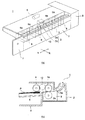
図3(a)は従来の一般的な給紙ユニットの斜視図、同図(b)はその要部断面図である。図3に示すように、給紙ローラ対3は、給紙ユニット1において用紙搬送方向に対して直交する方向の中央に、上下一対(フィードローラ3a,リタードローラ3b)として設けられる。
FIG. 3A is a perspective view of a conventional general paper feeding unit, and FIG. As shown in FIG. 3, the paper
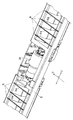
図4は、この従来の給紙ユニットのユニットフレーム前部を一部省略して示す斜視図である。図4に示すように、ユニットフレーム2内であってリタードローラ3bの両側には、用紙搬送方向に対して直交する方向に並列に、用紙搬送方向上流側が低く、下流側が高くなるような斜面9aを有するガイドリブ9が設けられる。ピックアップローラ6によって繰り出された用紙Pは、水平方向にガイドリブ9に突き当たった後、該ガイドリブ9にガイドされ斜め上方に向きを変えて送り出されることにより、給紙ユニット1から上方に延びる搬送路に送り出されることになる。
ここで、長期にわたり複写機を使用すると、ガイドリブ9はおびただしい数の用紙Pとの擦れ合いがあるため、給紙動作を繰り返すうちに徐々に摩耗し、その摩耗量が一定のレベル以上になると、表面摩擦が増したり、段差ができたりして、ピックアップローラ6によって繰り出された用紙Pが給紙ローラ対3に受け渡されることなくガイドリブ9に引っ掛かって止まるようになり、用紙ジャム等を引き起こす要因となる。こうなると、給紙ローラ対3が寿命に達していない時でも給紙ユニット1ごと交換になるため、ユーザの出費が高くなるという問題があった。
Here, when the copying machine is used over a long period of time, the
本発明は、ガイドリブの摩耗を軽減して用紙ジャム等の発生を長期にわたって抑制することのできる給紙ユニットを提供することを目的とする。 An object of the present invention is to provide a paper feed unit that can reduce the occurrence of paper jam and the like over a long period of time by reducing wear of guide ribs.
上記目的を達成するために本発明の給紙ユニットは、用紙収納部から繰り出された用紙を所定方向に給送する上下一対の給紙ローラ対と、該給紙ローラ対のうち下側の給紙ローラを回転可能に支持するユニットフレームと、該ユニットフレーム内にあって前記下側の給紙ローラの両側に設けられ用紙搬送方向上流側が低く、下流側が高くなる斜面を有するガイドリブとを備えた給紙ユニットにおいて、前記下側の給紙ローラと前記ガイドリブとの間に用紙をガイドするガイドコロを前記給紙ローラと同軸に設けたことを特徴とする。 In order to achieve the above object, a paper feed unit according to the present invention includes a pair of upper and lower paper feed rollers for feeding paper fed from a paper storage unit in a predetermined direction, and a lower feed of the paper feed roller pair. A unit frame that rotatably supports the paper roller, and a guide rib that is provided in both sides of the lower paper feed roller in the unit frame and has a slope that is lower on the upstream side in the paper transport direction and higher on the downstream side. In the paper feeding unit, a guide roller for guiding paper between the lower paper feeding roller and the guide rib is provided coaxially with the paper feeding roller.
この構成によると、用紙はガイドリブ表面に当接する前にガイドコロの用紙ガイド面に当接し、ガイドコロを回転させながら、一対の給紙ローラの間に挟持されて搬送される。これにより、給紙動作を繰り返しても用紙搬送方向の直交する方向の中央付近において、用紙の先端がガイドリブ表面に突き当たることがなくなり、ガイドリブの摩耗を軽減することができるため、用紙をガイドリブによって確実にガイドしながら搬送でき、用紙ジャムの発生を防止することができる。 According to this configuration, the paper comes into contact with the paper guide surface of the guide roller before coming into contact with the guide rib surface, and is conveyed while being sandwiched between the pair of paper feed rollers while rotating the guide roller. As a result, even if the paper feeding operation is repeated, the leading edge of the paper does not hit the surface of the guide rib near the center in the direction orthogonal to the paper conveyance direction, and wear of the guide rib can be reduced. Therefore, paper jam can be prevented.
そして、前記ガイドコロの用紙ガイド面を、前記ガイドリブの斜面より高い位置に配置することにより、確実に用紙を搬送できるようになる。また、前記ガイドコロを、前記下側の給紙ローラの両側に少なくとも1つずつ設けてもよい。また、前記下側の給紙ローラと前記ガイドコロとの間に、前記ガイドリブの斜面と面一となる斜面を有する補助ガイドリブを設けると、確実に用紙を搬送ができるようになるので望ましい。 By disposing the sheet guide surface of the guide roller at a position higher than the slope of the guide rib, the sheet can be reliably conveyed. Further, at least one guide roller may be provided on each side of the lower paper feed roller. In addition, it is desirable to provide an auxiliary guide rib having an inclined surface that is flush with the inclined surface of the guide rib between the lower sheet feeding roller and the guide roller, so that the sheet can be reliably conveyed.
本発明によれば、用紙はガイドリブ表面に当接する前にガイドコロの用紙ガイド面に当接し、ガイドコロを回転させながら、給紙ローラ対の間に挟持されて搬送される。これにより、給紙動作を繰り返しても用紙搬送方向に対して直交する方向の中央付近において、用紙の先端がガイドリブ表面に突き当たることがなくなり、ガイドリブの摩耗を軽減することができるため、用紙をガイドリブによって確実にガイドしながら搬送でき、用紙ジャム等の発生を長期にわたって抑制することのでき、給紙ユニットの寿命を延ばすことができる。 According to the present invention, the paper is brought into contact with the paper guide surface of the guide roller before coming into contact with the surface of the guide rib, and is nipped and conveyed between the pair of paper feed rollers while rotating the guide roller. Thus, even if the paper feeding operation is repeated, the front end of the paper does not hit the surface of the guide rib near the center in the direction orthogonal to the paper conveyance direction, and wear of the guide rib can be reduced. Therefore, the sheet can be conveyed while being reliably guided, the occurrence of paper jam or the like can be suppressed for a long time, and the life of the paper feeding unit can be extended.
以下、例えば複写機に搭載される給紙ユニットに適用した場合の本発明の実施の形態につき、図面を参照しつつ詳細に説明する。なお、本発明は、複写機に搭載される給紙ユニットに限定されることなく、印刷機、プリンタ等の画像形成装置に搭載される給紙ユニット全般に適用し得るものである。 Hereinafter, embodiments of the present invention applied to, for example, a paper feeding unit mounted on a copying machine will be described in detail with reference to the drawings. The present invention is not limited to the paper feeding unit mounted on the copying machine, but can be applied to all paper feeding units mounted on image forming apparatuses such as printing machines and printers.
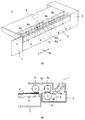
図1(a)は本発明に係る給紙ユニットの斜視図、(b)はその要部断面図である。図1に示す給紙ユニット1においては、ユニットフレーム2の内部であって用紙搬送方向(図中矢印Xの方向)に対して直交する方向(図中矢印Yの方向)の中央に、上下一対の給紙ローラ対3が設けられている。この給紙ローラ対3は、回転駆動側となるフィードローラ3aと、これにバネ圧等で圧接されるリタードローラ3bとから構成されている。このうち、一方のフィードローラ3aはその回転によって用紙Pを送り出す機能を果たし、もう一方のリタードローラ3bは二重送り等の防止機能(用紙の分離機能)を果たす。フィードローラ3a及びリタードローラ3bは、それぞれ別個の回転可能に回転軸に取り付けられている。加えて、ユニットフレーム2の内部には、用紙収納部となる給紙トレイ4の給紙台5に積載された用紙Pを繰り出すためのピックアップローラ6が設けられている。
FIG. 1A is a perspective view of a paper feeding unit according to the present invention, and FIG. In the
ピックアップローラ6の回転軸は、フィードローラ3aの回転駆動力を伝達する伝達機構12を介してフィードローラ3aの回転軸に対して異軸に連結されており、フィードローラ3aとともに回転するようになっている。このピックアップローラ6に対しては、給紙トレイ4側に設けられた図示せぬ付勢手段によって用紙Pが圧接されている。そして給紙時には、ピックアップローラ6の回転駆動によって用紙Pが最上位から順に繰り出され、この繰り出された用紙Pが上記一対の給紙ローラ対3に受け渡されるようになっている。
The rotation shaft of the
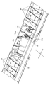
図2は、上記給紙ユニットのユニットフレーム前部を一部省略して示す斜視図である。図2に示すように、ユニットフレーム2内であってリタードローラ3bの両側には、用紙搬送方向に対して直交する方向に並列に、用紙搬送方向上流側が低く、下流側が高くなる斜面9aを有するガイドリブ9が複数設けられている。ガイドリブ9aの斜面9aは、リタードローラ3bの用紙搬送面と同程度の高さの位置に設定される。ガイドリブ9は、ABSやポリカーボネート等の硬質樹脂から成っている。
FIG. 2 is a perspective view in which a part of the unit frame front portion of the paper feeding unit is omitted. As shown in FIG. 2, in the
一方、ユニットフレーム2の一端側には、複写機の本体部分への固定部となる取付片7が設けられ、同他端側にはフィードローラ3aの駆動源となるモータやこれに付随した駆動力伝達系及び配線系統等を収納してなるケース部8が設けられている。この給紙ユニット1は、複写機の用紙収納位置、つまり複写機に給紙トレイ4をセットした状態での用紙Pの収納位置に対応して、複写機の本体部分(図示せず)に組み込まれる。
On the other hand, one end side of the
ピックアップローラ6によって繰り出された用紙Pは、水平方向にガイドリブ9に突き当たった後、該ガイドリブ9にガイドされ斜め上方に向きを変えて送り出されることにより、給紙ユニット1から上方に伸びる搬送路に送り出されることになる。
The paper P fed out by the
ここで、長期にわたり複写機を使用すると、ガイドリブ9はおびただしい数の用紙Pとの擦れ合いがあるため、給紙動作を繰り返すうちに徐々に摩耗し、その摩耗量が一定のレベル以上になると、表面摩擦が増したり、段差ができたりして、ピックアップローラ6によって繰り出された用紙Pが給紙ローラ対3に受け渡されることなくガイドリブ9に引っ掛かって止まるようになり、用紙ジャム等を引き起こす要因となる。このようなガイドリブ9の摩耗は、ピックアップローラ6によって積極的に繰り出される用紙Pの幅方向中央部が突き当たる場所である用紙搬送方向に対して直交する方向の中央付近、すなわち、リタードローラ3bの近傍で摩耗の度合いが大きくなる。反対に、用紙Pの幅方向の両端付近は比較的柔軟性があり、融通が利くので、用紙搬送方向に対して直交する方向の端に行くほど、ガイドリブ9の摩耗の度合いは小さくなる。
Here, when the copying machine is used over a long period of time, the
そこで、図示のように、リタードローラ3bに隣接して、用紙搬送方向に対して直交する方向のどちらか一方に一つのガイドコロ10をユニットフレーム2内に設けるようにした。このガイドコロ10は、リタードローラ3bの回転軸と同軸に、例えばベアリング等を介して回転自在に取り付けられている。ガイドコロ10の外径は、リタードローラ3bの外径よりも僅かに大きく設定されている。これによりガイドコロ10は、ガイドリブ9の斜面9aより高い位置に、該ガイドコロ外周面のうち最上部にあって用紙Pと接触する面(用紙ガイド面)10aを配置した状態となる。
Therefore, as shown in the drawing, one
上記構成からなる給紙ユニット1においては、ガイドリブ9表面に当接する前にガイドコロ10の用紙ガイド面10aに当接し、ガイドコロ10を回転させながら、給紙ローラ対3に挟持されて搬送される。これにより、給紙動作を繰り返しても用紙搬送方向に対して直交する方向の中央付近において、用紙Pの先端がガイドリブ9表面に突き当たることがなくなり、ガイドリブ9の摩耗を軽減することができるため、用紙Pをガイドリブ9によって確実にガイドしながら搬送でき、用紙ジャムの発生を防止することができる。また、電気的手段を全く採用せず、単純なメカ構造を採用しているため、きわめて安価である。
In the
なお、上記のようにピックアップローラ6によって繰り出された用紙Pの幅方向の中央部はガイドコロ10によってガイドされるため、リタードローラ3bとガイドコロ10との間にはガイドリブを不要であるが、図2に示すように、ガイドリブ9の斜面と面一となる斜面11aを有する補助ガイドリブ11を敢えて設けてもよい。この補助ガイドリブ11があることにより、A3用紙のようにサイズの大きな用紙Pを給紙する場合でも、用紙Pの幅方向の中央部が自重で撓むことがないため、ガイドコロ10の数を増やすなどして、用紙搬送方向の中央部に位置するガイドリブ9の絶対数が減ったとしても確実に用紙Pを搬送できる。
Since the central portion in the width direction of the paper P fed out by the
これは本実施形態では、リタードローラ3bに隣接して、用紙搬送方向に対して直交する方向のどちらか一方に一つのガイドコロ10をユニットフレーム2内に設けるようにした例を示したが、リタードローラ3bの両側に少なくとも1つずつガイドコロ10を設ける等、ガイドコロ10を複数設けても同様の効果が得られることはいうまでもない。また、ガイドコロ10の用紙ガイド面10aを、ガイドリブ9の斜面9aと同程度の高さの位置に配置しても構わない。
In this embodiment, an example in which one
1 給紙ユニット
2 ユニットフレーム
3 給紙ローラ対
3a フィードローラ(上側の給紙ローラ)
3b リタードローラ(下側の給紙ローラ)
4 給紙トレイ
5 給紙台(用紙収納部)
6 ピックアップローラ
7 取付片
8 ケース部
9 ガイドリブ
9a 斜面
10 ガイドコロ
10a 用紙ガイド面
11 補助ガイドリブ
12 伝達機構
P 用紙
DESCRIPTION OF
3b retard roller (lower feed roller)
4
6
Claims (4)
Priority Applications (1)
| Application Number | Priority Date | Filing Date | Title |
|---|---|---|---|
| JP2004113940A JP2005298090A (en) | 2004-04-08 | 2004-04-08 | Paper feeding unit |
Applications Claiming Priority (1)
| Application Number | Priority Date | Filing Date | Title |
|---|---|---|---|
| JP2004113940A JP2005298090A (en) | 2004-04-08 | 2004-04-08 | Paper feeding unit |
Publications (1)
| Publication Number | Publication Date |
|---|---|
| JP2005298090A true JP2005298090A (en) | 2005-10-27 |
Family
ID=35330108
Family Applications (1)
| Application Number | Title | Priority Date | Filing Date |
|---|---|---|---|
| JP2004113940A Pending JP2005298090A (en) | 2004-04-08 | 2004-04-08 | Paper feeding unit |
Country Status (1)
| Country | Link |
|---|---|
| JP (1) | JP2005298090A (en) |
Cited By (1)
| Publication number | Priority date | Publication date | Assignee | Title |
|---|---|---|---|---|
| US8442687B2 (en) | 2006-01-16 | 2013-05-14 | Sony Corporation | Control system, control method, and computer program |
-
2004
- 2004-04-08 JP JP2004113940A patent/JP2005298090A/en active Pending
Cited By (1)
| Publication number | Priority date | Publication date | Assignee | Title |
|---|---|---|---|---|
| US8442687B2 (en) | 2006-01-16 | 2013-05-14 | Sony Corporation | Control system, control method, and computer program |
Similar Documents
| Publication | Publication Date | Title |
|---|---|---|
| JP4997170B2 (en) | Paper feeding device and image forming apparatus | |
| US9026031B2 (en) | Medium accommodation cassette, medium feeding device, and recording apparatus | |
| US7455294B2 (en) | Paper-releasing mechanism | |
| JP2005298090A (en) | Paper feeding unit | |
| JP4968918B2 (en) | Sheet feeding apparatus and image forming apparatus | |
| JP6070148B2 (en) | Feeding device | |
| JP3679652B2 (en) | Automatic paper feeder and recording device | |
| JP2012159553A (en) | Paper conveyance device | |
| JP5617498B2 (en) | Image recording device | |
| JP3850320B2 (en) | Paper feeder | |
| JP2010241535A (en) | Recording medium feeding device and recording device | |
| JP4792073B2 (en) | Image forming apparatus | |
| JP4327032B2 (en) | Paper feed tray, paper feed device, and image forming apparatus | |
| JP3760651B2 (en) | Sheet transport device | |
| JP2009242055A (en) | Sheet feeder | |
| JP3921944B2 (en) | Paper feeder | |
| JP4717759B2 (en) | Sheet discharge mechanism and recording apparatus | |
| JP2007297198A (en) | Conveying device, image forming device, and method of separating conveying rollers | |
| JP6730669B2 (en) | Medium feeding device, image reading device, recording device | |
| JP2007145591A (en) | Paper feeder | |
| JP2008133078A (en) | Sheet feeder | |
| JP2007161384A (en) | Transport device | |
| JP2014172688A (en) | Image forming device | |
| JP2006016174A (en) | Paper feeding device | |
| JP2000219335A (en) | Sheet feeding apparatus and image forming apparatus having the same |