JP5106212B2 - Image forming apparatus - Google Patents

Image forming apparatus Download PDF

Info

Publication number
JP5106212B2
JP5106212B2 JP2008090200A JP2008090200A JP5106212B2 JP 5106212 B2 JP5106212 B2 JP 5106212B2 JP 2008090200 A JP2008090200 A JP 2008090200A JP 2008090200 A JP2008090200 A JP 2008090200A JP 5106212 B2 JP5106212 B2 JP 5106212B2
Authority
JP
Japan
Prior art keywords
process cartridge
cleaning member
image forming
cleaning
laser
Prior art date
Legal status (The legal status is an assumption and is not a legal conclusion. Google has not performed a legal analysis and makes no representation as to the accuracy of the status listed.)
Expired - Fee Related
Application number
JP2008090200A
Other languages
Japanese (ja)
Other versions
JP2009244541A5 (en
JP2009244541A (en
Inventor
金子  保
健一 冨田
一志 稲生
Current Assignee (The listed assignees may be inaccurate. Google has not performed a legal analysis and makes no representation or warranty as to the accuracy of the list.)
Canon Inc
Original Assignee
Canon Inc
Priority date (The priority date is an assumption and is not a legal conclusion. Google has not performed a legal analysis and makes no representation as to the accuracy of the date listed.)
Filing date
Publication date
Application filed by Canon Inc filed Critical Canon Inc
Priority to JP2008090200A priority Critical patent/JP5106212B2/en
Priority to US12/414,438 priority patent/US8203586B2/en
Priority to CN201110147763.5A priority patent/CN102213940B/en
Priority to CN2009101325404A priority patent/CN101551633B/en
Publication of JP2009244541A publication Critical patent/JP2009244541A/en
Publication of JP2009244541A5 publication Critical patent/JP2009244541A5/ja
Application granted granted Critical
Publication of JP5106212B2 publication Critical patent/JP5106212B2/en
Expired - Fee Related legal-status Critical Current
Anticipated expiration legal-status Critical

Links

Images

Landscapes

  • Facsimiles In General (AREA)
  • Laser Beam Printer (AREA)
  • Exposure Or Original Feeding In Electrophotography (AREA)
  • Electrophotography Configuration And Component (AREA)

Description

本発明は複写機、プリンタ、ファクシミリ等の画像形成装置に関し、特に光学ユニットの光照射開口部に設けた透過部材を清掃可能な画像形成装置に関する。   The present invention relates to an image forming apparatus such as a copying machine, a printer, and a facsimile, and more particularly to an image forming apparatus capable of cleaning a transmission member provided in a light irradiation opening of an optical unit.

レーザビームプリンタや複写機等の画像形成装置は、像担持体である感光体ドラムに画信号に応じたレーザ光を照射して静電潜像を形成し、この静電潜像をトナーによって現像して可視像化する。このような画像形成装置は、動作中にレーザ光が外部に漏出しないように、開閉可能な開閉カバーを有する本体カバーによって覆っている。   Image forming apparatuses such as laser beam printers and copiers form an electrostatic latent image by irradiating a photosensitive drum, which is an image carrier, with laser light corresponding to an image signal, and developing the electrostatic latent image with toner. To visualize it. Such an image forming apparatus is covered with a main body cover having an openable / closable cover so that laser light does not leak outside during operation.

しかし、プロセスカートリッジ等の消耗品の交換や、操作上紙詰まりを除去する場合、あるいは保守点検の際など、メインスイッチの入力中に開閉カバーを開けることがある。特にレーザ光の場合は、開閉カバーが開いた状態において、インターロックスイッチが誤作動してもレーザ光が装置外に漏れないようにする必要がある。   However, the opening / closing cover may be opened while the main switch is being input, such as when replacing consumables such as process cartridges, removing paper jams during operation, or during maintenance. In particular, in the case of laser light, it is necessary to prevent the laser light from leaking outside the apparatus even when the interlock switch malfunctions when the open / close cover is open.

そこで、レーザシャッタ装置が用いられている。レーザシャッタ装置はレーザ光学走査装置又はそれを用いた画像形成装置内に配置され、感光体ドラムを含むプロセスカートリッジの着脱や、その際開閉される画像形成装置の開閉カバーの開閉動作に連動してシャッタが動作するように構成されている。すなわち、レーザシャッタ装置は、ユーザ、サービスマンがプロセスカートリッジの着脱、紙詰まりの処理等の目的で画像形成装置の開閉カバーを開けたときに、レーザ光の光路を遮ることで、ユーザがレーザ光にさらされるのを防ぐためのものである。   Therefore, a laser shutter device is used. The laser shutter device is disposed in the laser optical scanning device or an image forming apparatus using the laser optical device. The shutter is configured to operate. In other words, the laser shutter device blocks the laser light path when the user or service person opens the open / close cover of the image forming apparatus for the purpose of attaching or detaching a process cartridge or handling a paper jam. This is to prevent exposure.

例えば、特許文献1に開示されているように、レーザ光を反射する折り返しミラーの全長を覆う形状のレーザシャッタを回動可能に取り付け、プロセスカートリッジの着脱や紙詰まりを除去する時に開閉する開閉カバーに連動して前記レーザシャッタを回動させて折り返しミラーに至るレーザ光路を遮断するようにしたものがある。   For example, as disclosed in Patent Document 1, a laser shutter having a shape that covers the entire length of a folding mirror that reflects laser light is rotatably attached, and an open / close cover that opens and closes when a process cartridge is attached or detached or a paper jam is removed. In some cases, the laser shutter is rotated in conjunction with the laser beam so as to block the laser light path reaching the folding mirror.

一方、近年の電子写真方式の画像形成装置は、現像剤としてトナーを使用するため、画像形成装置内でトナーが飛散し、塵や埃が浮遊することがある。画像形成装置の露光手段であるレーザスキャナは、トナー、塵、埃等を嫌うため、レーザスキャナ内部へトナー、塵、埃等が侵入しないように、その内部を密閉状態としている。   On the other hand, since recent electrophotographic image forming apparatuses use toner as a developer, the toner may scatter in the image forming apparatus and dust and dust may float. Since the laser scanner, which is an exposure unit of the image forming apparatus, dislikes toner, dust, dust, and the like, the inside of the laser scanner is sealed so that toner, dust, dust, and the like do not enter the laser scanner.

画像形成装置は、レーザスキャナから出射されるレーザ光が通過する開口部を有している。この開口部からトナー、塵、埃等がレーザスキャナ内部へ侵入するのを防止することを目的として、開口部にレーザ光が通過可能なカバーガラスを取り付けている。   The image forming apparatus has an opening through which laser light emitted from the laser scanner passes. In order to prevent toner, dust, dust, and the like from entering the laser scanner from the opening, a cover glass through which the laser beam can pass is attached to the opening.

このような構成から、プロセスカートリッジ内の現像器から落下・浮遊するトナー、塵、埃がレーザ光の光路内に侵入し、カバーガラスに付着して光路を遮ることで、印字画像の濃度低下や画像の欠落が発生することがあった。よって、濃度低下や画像の欠落を防止するためには、カバーガラス上にトナーや塵、埃等が付着しない構成、もしくは付着したものを清掃する構成が必要となる。   With such a configuration, toner, dust, or dust that falls or floats from the developing device in the process cartridge enters the optical path of the laser beam and adheres to the cover glass to block the optical path. Missing images may occur. Therefore, in order to prevent density reduction and image loss, a configuration in which toner, dust, dust or the like does not adhere to the cover glass, or a configuration in which the adhering material is cleaned is necessary.

そこで、ユーザやサービスマンが画像形成装置内部にアクセスし、カバーガラスを柔らかい布等でクリーニングを行うことされていた。しかし、カバーガラスのエリアはその面積が小さい上に、カバーガラス表面を傷つけないようにクリーニングしなければならなかったため、非常にやりにくく、確実にクリーニングすることに苦労していた。   Therefore, a user or a service person accesses the inside of the image forming apparatus and cleans the cover glass with a soft cloth or the like. However, since the area of the cover glass is small and it must be cleaned so as not to damage the surface of the cover glass, it is very difficult to perform and it has been difficult to clean.

この課題を解決するために、特許文献2に開示されているように、防塵ガラスに付着したトナー、塵、埃等を除去できるクリーニング構成が提案されている。具体的には、ユーザやサービスマンが光走査装置に備わっている清掃部材を防塵ガラスに沿ってスライドさせることで、防塵ガラスに付着したトナー、塵、埃等を除去することができる構成を実現している。   In order to solve this problem, as disclosed in Patent Document 2, there has been proposed a cleaning configuration capable of removing toner, dust, dust and the like adhering to the dust-proof glass. Specifically, a configuration in which toner, dust, dust, etc. attached to the dust-proof glass can be removed by sliding a cleaning member provided in the optical scanning device along the dust-proof glass by the user or service person is realized. doing.

特開平11−337859号JP-A-11-337859 特開2005−246901号JP 2005-246901 A

近年、タンデム型カラー画像形成装置は小型化、高速出力化が進み、画像形成の主要な要素をコンパクトに配置、構成することが重要なテーマとなっている。特に、複数の感光体ドラム、複数のレーザ光を使用するタンデム式カラー画像形成装置においては、各色の画像形成部が必要になり、画像形成部をいかにコンパクト設計を行うかが課題であった。   In recent years, tandem color image forming apparatuses have been reduced in size and increased in output speed, and it has become an important theme to arrange and configure the main elements of image formation in a compact manner. In particular, in a tandem color image forming apparatus using a plurality of photosensitive drums and a plurality of laser beams, an image forming unit for each color is required, and how to design the image forming unit compactly has been a problem.

当然タンデム式カラー画像形成装置では、ユーザ保護のためのレーザシャッタ装置も複数必要になり、機構が複雑になってしまう。また、レーザシャッタ機構を配置するスペースが感光体ドラムとレーザスキャナの間に必要となり、作像エリアの各要素の配置自由度が失われ、装置の小型化の障害になってしまっていた。   Naturally, the tandem color image forming apparatus requires a plurality of laser shutter devices for user protection, and the mechanism becomes complicated. In addition, a space for arranging the laser shutter mechanism is required between the photosensitive drum and the laser scanner, so that the degree of freedom of arrangement of each element in the image forming area is lost, which hinders downsizing of the apparatus.

また、特許文献2に示すように、清掃部材をスライドさせて防塵ガラスを清掃する構成では、ユーザやサービスマンが清掃部材を移動させる必要があり、清掃操作に煩わしさがあった。   Moreover, as shown in Patent Document 2, in the configuration in which the dust-proof glass is cleaned by sliding the cleaning member, it is necessary for the user or service person to move the cleaning member, which causes troublesome cleaning operations.

本発明は上記点に鑑みてなされたものであり、その目的は、省スペース、かつシンプルな構成で操作性よく透過部材上の異物を清掃することが可能な画像形成装置を提供するものである。   The present invention has been made in view of the above points, and an object of the present invention is to provide an image forming apparatus capable of cleaning foreign matter on a transmission member with a small space and a simple configuration with good operability. .

上記課題を解決するための本発明における代表的な手段は、トナー像を担持する像担持体と、装置本体に挿入されるカートリッジを装着するカートリッジ装着部と、前記像担持体に光照射をするための開口部を有し、前記開口部に光が透過する透過部材を備えた光学ユニットと、前記光学ユニットの開口部から前記像担持体に照射される光の光路を遮る閉鎖位置と開放する開放位置とに移動可能な光シャッタ部材と、記透過部材に対して移動して前記透過部材を清掃する清掃部材と、を有する画像形成装置であって、前記清掃部材は、前記光シャッタ部材に対して移動可能に前記光シャッタ部材に支持され装置本体へ挿入される前記カートリッジに係合して前記透過部材に対して移動し、記光シャッタ部材が前記閉鎖位置にある状態で前記カートリッジを挿入する際に、前記光シャッタ部材が、前記カートリッジの挿入動作に伴って前記清掃部材が移動する方向に沿って移動して該閉鎖位置から移動すること規制する規制部材を有することを特徴とする。 Typical means of the present invention to solve the above problems, an image bearing member you bearing a toner image, and a cartridge mounting portion for mounting a cartridge which is inserted into the apparatus main body, the light irradiation to the image bearing member has an opening for an optical unit in which light with a to that transparently member transmissive to the opening, a closed position blocking the optical path of light irradiated to the image carrier from the opening of the optical unit an image forming apparatus having a cleaning member for cleaning the transparent member by moving the optical shutter member movable, with respect to the front Symbol transmitting member to an open position to open the said cleaning member, the is supported by the optical shutter member movable relative to the light shutter member, engaged with the cartridge that is inserted into the apparatus main assembly to move relative to the transmission member, before Symbol light shutter member the closed position in any conditions When inserting the serial cartridge, the light shutter member, having a restricting member which restricts movement from the closed position by moving the cleaning member with the inserting operation of the cartridge along the direction of movement It is characterized by.

本発明にあっては、カートリッジの挿抜動作に伴って清掃部材が移動する。このため、カートリッジを装置本体に挿抜するだけで清掃部材により透過部材を清掃することができる。   In the present invention, the cleaning member moves in accordance with the cartridge insertion / extraction operation. For this reason, the transmission member can be cleaned by the cleaning member only by inserting and removing the cartridge from the apparatus main body.

また、カートリッジを抜き取る動作中にカートリッジと清掃部材の係合が解除されるので、清掃操作性が向上する。   Further, since the engagement between the cartridge and the cleaning member is released during the operation of removing the cartridge, the cleaning operability is improved.

次に本発明の一実施形態に係る画像形成装置について、図面を参照して具体的に説明する。   Next, an image forming apparatus according to an embodiment of the present invention will be specifically described with reference to the drawings.

〔第1実施形態〕
図1は第1実施形態に係る画像形成装置の一態様であるカラーレーザプリンタ100の全体構成を示す縦断面図である。まず、画像形成装置の全体構成について概略説明する。
[First Embodiment]
FIG. 1 is a longitudinal sectional view showing an overall configuration of a color laser printer 100 which is an aspect of the image forming apparatus according to the first embodiment. First, the overall configuration of the image forming apparatus will be outlined.

[画像形成装置の全体構成]
図1に示すカラーレーザプリンタ100は、第1から第4画像形成部を構成する4個のプロセスカートリッジ7(7a,7b,7c,7d)が装着されている。各画像形成部は、順にイエロー、マゼンタ、シアン、ブラックの各色画像を形成するものであり、トナーの色が異なる以外は同じ構成である。そこで、図1に示した符号a,b,c,dはそれぞれ、イエロー、マゼンタ、シアン、ブラックの各画像形成部に対応した部材を示すが、以下の説明では、特に色を区別する必要がない場合には、符号a,b,c,dは省略する。
[Entire configuration of image forming apparatus]
The color laser printer 100 shown in FIG. 1 is equipped with four process cartridges 7 (7a, 7b, 7c, 7d) constituting the first to fourth image forming units. Each image forming unit sequentially forms each color image of yellow, magenta, cyan, and black, and has the same configuration except that the color of the toner is different. Therefore, reference symbols a, b, c, and d shown in FIG. 1 indicate members corresponding to the image forming units of yellow, magenta, cyan, and black, respectively, but in the following description, it is particularly necessary to distinguish colors. If not, the symbols a, b, c and d are omitted.

各プロセスカートリッジ7は像担持体としての感光体ドラム1を備えており、感光体ドラム1の周囲には、その回転方向に従って順に、帯電手段としての帯電手段2、現像ユニット4、クリーニング手段8が一体的にカートリッジ化されて画像形成装置本体に着脱可能に装着されている。   Each process cartridge 7 includes a photosensitive drum 1 as an image carrier. A charging unit 2, a developing unit 4, and a cleaning unit 8 are sequentially arranged around the photosensitive drum 1 in accordance with the rotation direction. The cartridge is integrally formed and is detachably attached to the main body of the image forming apparatus.

プロセスカートリッジ7は現像手段となる現像ユニット4とクリーナユニット5で構成されている。現像ユニット4は、現像ローラ24と、現像剤塗布ローラ25、及びトナー容器を有している。クリーナユニット5は、感光体ドラム1と、帯電ローラ2と、クリーニング手段となるドラムクリーニングブレード8及び廃トナー容器とを有している。   The process cartridge 7 includes a developing unit 4 and a cleaner unit 5 which are developing means. The developing unit 4 includes a developing roller 24, a developer application roller 25, and a toner container. The cleaner unit 5 includes a photosensitive drum 1, a charging roller 2, a drum cleaning blade 8 serving as a cleaning unit, and a waste toner container.

また、プロセスカートリッジ7の上方には、感光体ドラム1に当接して回転可能な中間転写ベルトユニット30が配置され、プロセスカートリッジ7の下方には光学ユニットとしてのレーザスキャナ3が配置されている。   Further, an intermediate transfer belt unit 30 that is rotatable in contact with the photosensitive drum 1 is disposed above the process cartridge 7, and a laser scanner 3 as an optical unit is disposed below the process cartridge 7.

像担持体としての感光体ドラム1は、アルミニウム製シリンダの外周面に有機光導伝体層(OPC)を塗布して構成したものであり、その両端部をフランジによって回転自在に支持されている。そして、一方の端部に駆動モータ(不図示)から駆動力を伝達することにより、図1の矢印に示す時計回り方向に回転駆動される。   A photosensitive drum 1 as an image carrier is configured by applying an organic photoconductive layer (OPC) to the outer peripheral surface of an aluminum cylinder, and both ends thereof are rotatably supported by flanges. Then, a driving force is transmitted to one end portion from a driving motor (not shown), thereby being rotated in the clockwise direction indicated by the arrow in FIG.

帯電手段2は、ローラ状に形成された導電性ローラで、このローラを感光体ドラム1表面に当接させるとともに、電源(不図示)によって帯電バイアス電圧を印加することにより、感光体ドラム1表面を一様に帯電させるものである。   The charging means 2 is a conductive roller formed in a roller shape. The roller is brought into contact with the surface of the photosensitive drum 1 and a charging bias voltage is applied by a power source (not shown) to thereby surface the surface of the photosensitive drum 1. Is uniformly charged.

レーザスキャナ3は、プロセスカートリッジ7の鉛直下方に配置され、画像信号に基づく露光を各感光体ドラム1に対して行う。   The laser scanner 3 is disposed vertically below the process cartridge 7 and performs exposure based on the image signal for each photosensitive drum 1.

現像ユニット4a,4b,4c,4dは、それぞれイエロー(Y)、マゼンタ(M)、シアン(C)、ブラック(K)の各色のトナーを収納したトナー収納部、感光体表面に隣接し、駆動部(不図示)により回転駆動されると共に、現像バイアス電源(不図示)により現像バイアス電圧を印加することにより現像を行う現像ローラ等から構成される。   The developing units 4a, 4b, 4c, and 4d are adjacent to the toner storage unit that stores toner of each color of yellow (Y), magenta (M), cyan (C), and black (K), and the surface of the photoreceptor, respectively. The image forming apparatus includes a developing roller and the like that are rotated by a unit (not shown) and that develops by applying a developing bias voltage from a developing bias power source (not shown).

上述の構成により,感光体ドラム1は、帯電ローラ2によって所定の負極性の電位に帯電された後、レーザスキャナ3によってそれぞれ静電潜像が形成される。この静電潜像は現像ユニット4によって反転現像されて負極性のトナーが付着され、それぞれY、M、C、Kのトナー像が形成される。   With the above-described configuration, the photosensitive drum 1 is charged to a predetermined negative potential by the charging roller 2 and then an electrostatic latent image is formed by the laser scanner 3. The electrostatic latent image is reversely developed by the developing unit 4 and negative toner is attached to form Y, M, C, and K toner images, respectively.

中間転写ベルトユニット30は、中間転写ベルト12eが駆動ローラ12f、テンションローラ12gに張架されており、該テンションローラ12gが矢印E方向に張力をかけている。また、各感光体ドラム1に対向して、中間転写ベルト12eの内側に一次転写ローラ12が配設されており、バイアス印加手段(不図示)により転写バイアスを印加する構成となっている。   In the intermediate transfer belt unit 30, an intermediate transfer belt 12e is stretched around a drive roller 12f and a tension roller 12g, and the tension roller 12g applies tension in the direction of arrow E. Further, a primary transfer roller 12 is disposed inside the intermediate transfer belt 12e so as to face each photosensitive drum 1, and is configured to apply a transfer bias by bias applying means (not shown).

感光体ドラム1上に形成されたトナー像は、各感光体ドラム1が図1の矢印方向に回転し、中間転写ベルト12eが矢印F方向に回転し、さらに一次転写ローラ12に正極性のバイアスを印加することにより、感光体ドラム1a上のトナー像から順次、中間転写ベルト12e上に一次転写される。そして、4色のトナー像が重なった状態で二次転写部15まで搬送される。   In the toner image formed on the photosensitive drum 1, each photosensitive drum 1 rotates in the direction of the arrow in FIG. 1, the intermediate transfer belt 12e rotates in the direction of the arrow F, and the positive bias is applied to the primary transfer roller 12. Is applied to the intermediate transfer belt 12e sequentially from the toner image on the photosensitive drum 1a. Then, the four color toner images are conveyed to the secondary transfer unit 15 in a state where they overlap.

給送装置13は、シートSを収納するシートカセット11内からシートSを給送する給送ローラ9と、給送されたシートSを搬送する搬送ローラ対10とを有している。   The feeding device 13 includes a feeding roller 9 that feeds the sheet S from within the sheet cassette 11 that stores the sheet S, and a conveyance roller pair 10 that conveys the fed sheet S.

シートカセット11は、図1中本体手前方向へ引き抜くことができるよう構成されており、ユーザはシートカセット11を引き抜き、装置本体から取り外した後、シートSをセットし装置本体へ挿入することでシート補給が完了する。   The sheet cassette 11 is configured so that it can be pulled out toward the front side of the main body in FIG. 1. After the user pulls out the sheet cassette 11 and removes it from the apparatus main body, the sheet S is set and inserted into the apparatus main body. Supply is completed.

シートカセット11に収納されたシートSは、給送ローラ9に圧接され、分離パッド23によって一枚ずつ分離され(摩擦片分離方式)搬送される。   The sheets S stored in the sheet cassette 11 are pressed against the feeding roller 9, separated one by one by the separation pad 23 (friction piece separation method), and conveyed.

そして、給送装置13から搬送されたシートSはレジストローラ対17によって二次転写部15に搬送される。   Then, the sheet S conveyed from the feeding device 13 is conveyed to the secondary transfer unit 15 by the registration roller pair 17.

二次転写部15において、二次転写ローラ16に正極性のバイアスを印加することにより、搬送されたシートSに、中間転写ベルト12e上の4色のトナー像を二次転写する。   In the secondary transfer unit 15, a four-color toner image on the intermediate transfer belt 12 e is secondarily transferred onto the conveyed sheet S by applying a positive bias to the secondary transfer roller 16.

トナー像が転写されたシートは定着手段である定着部14において、熱及び圧力が印加されてトナー像が定着され、排出ローラ対20によって排出トレイ21に排出される。   The sheet onto which the toner image has been transferred is applied with heat and pressure in the fixing unit 14 serving as fixing means to fix the toner image, and is discharged onto the discharge tray 21 by the discharge roller pair 20.

一方、トナー像転写後に、感光体ドラム1表面に残ったトナーは、クリーニングブレード8によって除去され、除去されたトナーはクリーナユニット5内の廃トナー容器に回収される。   On the other hand, the toner remaining on the surface of the photosensitive drum 1 after the toner image transfer is removed by the cleaning blade 8, and the removed toner is collected in a waste toner container in the cleaner unit 5.

また、シートSへの二次転写後に中間転写ベルト12e上に残ったトナーは、転写ベルトクリーニング装置22によって除去され、除去されたトナーは、廃トナー搬送路(不図示)を通過し、装置奥面部に配置された廃トナー回収容器(不図示)へと回収される。   Further, the toner remaining on the intermediate transfer belt 12e after the secondary transfer to the sheet S is removed by the transfer belt cleaning device 22, and the removed toner passes through a waste toner conveyance path (not shown) and passes through the back of the device. The toner is collected into a waste toner collecting container (not shown) disposed on the surface.

[プロセスカートリッジの着脱構成]
次にカラーレーザプリンタ100におけるプロセスカートリッジ7の着脱構成について説明する。図2は第1実施形態に係る画像形成装置における、プロセスカートリッジ7の着脱方法、シートカセット11の着脱方法を示した斜視図である。
[Process cartridge installation / removal configuration]
Next, a configuration for attaching and detaching the process cartridge 7 in the color laser printer 100 will be described. FIG. 2 is a perspective view showing a method for attaching / detaching the process cartridge 7 and a method for attaching / detaching the sheet cassette 11 in the image forming apparatus according to the first embodiment.

カラーレーザプリンタ100においては、シートカセット11へのシートの補給、プロセスカートリッジ7の着脱、プリントされたシートの回収は、装置正面側から操作可能となっている。また、プロセスカートリッジ7の着脱は、感光体ドラム1の回転軸方向、かつ装置本体正面側に着脱できる構成となっている。   In the color laser printer 100, supply of sheets to the sheet cassette 11, attachment / detachment of the process cartridge 7, and collection of printed sheets can be operated from the front side of the apparatus. The process cartridge 7 can be attached / detached in the direction of the rotation axis of the photosensitive drum 1 and on the front side of the apparatus main body.

図2に示すように、装置本体内にはカートリッジ装着部60が形成され、プロセスカートリッジ7の挿入、抜き取りをガイドするガイド部が設けられている。プロセスカートリッジ7の着脱は、開閉カバー(図示せず)を開き、前記ガイド部に沿わせてプロセスカートリッジ7を感光体ドラムの長手方向に挿抜することによって行う。   As shown in FIG. 2, a cartridge mounting portion 60 is formed in the apparatus main body, and a guide portion for guiding insertion and extraction of the process cartridge 7 is provided. The process cartridge 7 is attached / detached by opening an open / close cover (not shown) and inserting / removing the process cartridge 7 in the longitudinal direction of the photosensitive drum along the guide portion.

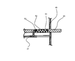
図3に示すように、ガイド部33はプロセスカートリッジ7の下部をガイドするガイドレールとして構成されている。このガイド部33は、プロセスカートリッジ7とレーザスキャナ3を仕切る仕切り板31に設けられ、プロセスカートリッジ7に一体的に形成された挿入リブ18をガイドする溝が形成されている。また、ガイド部33はカートリッジ挿入方向の奥側端部が他の部分よりも上方へ湾曲している(図10参照)。このため、後述するようにガイド部33に沿わせてプロセスカートリッジ7を挿入すると、挿入終期には下から上へ僅かに移動するように装着される。   As shown in FIG. 3, the guide portion 33 is configured as a guide rail that guides the lower portion of the process cartridge 7. The guide portion 33 is provided in a partition plate 31 that partitions the process cartridge 7 and the laser scanner 3, and a groove that guides an insertion rib 18 that is formed integrally with the process cartridge 7 is formed. Further, the back end of the guide portion 33 in the cartridge insertion direction is curved upward from the other portions (see FIG. 10). Therefore, when the process cartridge 7 is inserted along the guide portion 33 as will be described later, the process cartridge 7 is mounted so as to move slightly from the bottom to the top at the end of the insertion.

[レーザシャッタと清掃部材]
次に、図3を用いてプロセスカートリッジ7、レーザシャッタ35、及び清掃部材61について説明をする。
[Laser shutter and cleaning member]
Next, the process cartridge 7, the laser shutter 35, and the cleaning member 61 will be described with reference to FIG.

本実施形態のレーザスキャナ3は、プロセスカートリッジ7の下方に配置され、上方に位置する感光体ドラム1に光照射するために、ユニット上部であって感光体ドラム1の長手方向に細長い開口部80が設けられている。ユニット上部に設けられた開口部80からレーザスキャナ3の内部に塵、埃、トナー等が落下し易いため、この開口部80には光が透過する透過部材であるカバーガラス34が取り付けられ、開口部80を塞いで密閉している。   The laser scanner 3 of the present embodiment is disposed below the process cartridge 7 and has an opening 80 that is elongated in the longitudinal direction of the photosensitive drum 1 at the top of the unit in order to irradiate the photosensitive drum 1 positioned above. Is provided. Since dust, dust, toner, etc. easily fall into the laser scanner 3 from the opening 80 provided in the upper part of the unit, a cover glass 34, which is a transmission member that transmits light, is attached to the opening 80. The part 80 is closed and sealed.

ここで、カバーガラス34は、長尺形状であり、感光体ドラム1に向けて出射された光を透過するために感光体ドラム1の回転軸方向と長尺状のカバーガラス34の長手方向が略一致するように配置されている。   Here, the cover glass 34 has a long shape, and in order to transmit the light emitted toward the photosensitive drum 1, the rotation axis direction of the photosensitive drum 1 and the longitudinal direction of the long cover glass 34 are different. It arrange | positions so that it may correspond substantially.

また、カバーガラス34の直上にはレーザ光を遮る位置に、黒色のABS樹脂で成形された光シャッタ部材であるレーザシャッタ35が配置されている。このレーザシャッタ35はカバーガラス34を覆うように細長形状に形成され、レーザスキャナ3から感光体ドラム1に照射される光の光路を遮る位置(閉鎖位置)と開放する位置(開放位置)とに移動可能となっている。図3に示すように、レーザシャッタ35が閉鎖位置にあるときは、カバーガラス34を透過したレーザ光はレーザシャッタ35で遮られ、感光体ドラム1に照射されることはない。   A laser shutter 35, which is an optical shutter member formed of black ABS resin, is disposed immediately above the cover glass 34 at a position where the laser light is blocked. The laser shutter 35 is formed in an elongated shape so as to cover the cover glass 34, and has a position (blocking position) for blocking the optical path of light irradiated from the laser scanner 3 to the photosensitive drum 1 and a position (open position) for opening. It is movable. As shown in FIG. 3, when the laser shutter 35 is in the closed position, the laser light transmitted through the cover glass 34 is blocked by the laser shutter 35 and is not irradiated to the photosensitive drum 1.

そして、このレーザシャッタ35は、弾性部材で構成され、弾性変形可能に構成されている。本実施形態ではレーザシャッタ35をABS樹脂で構成している。   The laser shutter 35 is formed of an elastic member and is configured to be elastically deformable. In this embodiment, the laser shutter 35 is made of ABS resin.

また、レーザシャッタ35には、その外周を囲うような形態でカバーガラス34を清掃するための清掃部材61が嵌められている。清掃部材61は主にベース部材62、拭き取り部材64で構成されている。本実施形態のベース部材62は、約20mm程度の長さのABS樹脂で形成されたものであり、レーザシャッタ35の長手方向にスライド移動自在にレーザシャッタ35によって支持されている。そして、清掃部材61がレーザシャッタ35にガイドされて長尺状のカバーガラス34の長手方向に移動することでカバーガラス34を拭き取り可能となっている。   The laser shutter 35 is fitted with a cleaning member 61 for cleaning the cover glass 34 so as to surround the outer periphery thereof. The cleaning member 61 is mainly composed of a base member 62 and a wiping member 64. The base member 62 of the present embodiment is made of ABS resin having a length of about 20 mm, and is supported by the laser shutter 35 so as to be slidable in the longitudinal direction of the laser shutter 35. The cleaning member 61 is guided by the laser shutter 35 and moved in the longitudinal direction of the long cover glass 34 so that the cover glass 34 can be wiped off.

清掃部材61のベース部材62上部にはタブ63が一体的に形成されている。このタブ63は、プロセスカートリッジ7を着脱する際、プロセスカートリッジ7の一部と係合するものであり、これによりプロセスカートリッジ7の挿抜動作に連動して清掃部材61がレーザシャッタ35の長手方向に沿ってスライドする。   A tab 63 is integrally formed on the upper part of the base member 62 of the cleaning member 61. The tab 63 is engaged with a part of the process cartridge 7 when the process cartridge 7 is attached / detached, whereby the cleaning member 61 is moved in the longitudinal direction of the laser shutter 35 in conjunction with the insertion / extraction operation of the process cartridge 7. Slide along.

ベース部材62の下面部には、拭き取り部材64が貼り付けられている。本実施形態の拭き取り部材64は、厚さ2mm、硬度100N前後の発泡ウレタンと厚さ1.5mmのポリエステル不織布とを溶着処理で接着したものを用いている。図3に示すように、プロセスカートリッジ7が装着された状態においては、拭き取り部材64のポリエステル不織布とカバーガラス34とは離間した位置に配置されている。   A wiping member 64 is attached to the lower surface portion of the base member 62. The wiping member 64 of the present embodiment uses a urethane foam having a thickness of 2 mm and a hardness of around 100 N and a polyester nonwoven fabric having a thickness of 1.5 mm adhered by a welding process. As shown in FIG. 3, in the state where the process cartridge 7 is mounted, the polyester nonwoven fabric of the wiping member 64 and the cover glass 34 are disposed at positions separated from each other.

(レーザシャッタの支持構成)
次にレーザシャッタ35の支持方法について、図4、図5を用いて説明する。図4は図3と同様にカラーレーザプリンタ100を正面側からみた部分断面図であり、図5は装置上方よりみた断面図である。
(Laser shutter support structure)
Next, a method for supporting the laser shutter 35 will be described with reference to FIGS. 4 is a partial cross-sectional view of the color laser printer 100 as seen from the front side as in FIG. 3, and FIG. 5 is a cross-sectional view of the color laser printer 100 as seen from above the apparatus.

図5に示すように、レーザシャッタ35はリンク部材によって開放位置と閉鎖位置とに移動可能となっている。具体的には、レーザシャッタ35の長手方向両端部は、その下方に配置されたリンク部材を構成する揺動アーム38,39によって支持されている。前記揺動アーム38,39は揺動支点ボス42,43を中心に回動可能であって、回動端部側が軸部によりレーザシャッタ35の両端部と枢着されている。   As shown in FIG. 5, the laser shutter 35 is movable between an open position and a closed position by a link member. Specifically, both ends in the longitudinal direction of the laser shutter 35 are supported by swinging arms 38 and 39 constituting a link member disposed below the laser shutter 35. The oscillating arms 38 and 39 are rotatable about the oscillating fulcrum bosses 42 and 43, and the rotating end portions are pivotally attached to both end portions of the laser shutter 35 by shaft portions.

また、図4に示すように、レーザシャッタ35と揺動アーム38,39の間には、レーザシャッタ35をカバーガラス34と離れる方向へ付勢するような圧縮バネ65が取り付けられている。つまりレーザシャッタ35は、図4の上方へ付勢されており、揺動アーム38,39の軸端部に取り付けられたEリング66によって抜け方向に規制されて位置決めされている。   Further, as shown in FIG. 4, a compression spring 65 is attached between the laser shutter 35 and the swing arms 38 and 39 so as to urge the laser shutter 35 in a direction away from the cover glass 34. That is, the laser shutter 35 is urged upward in FIG. 4 and is positioned by being regulated in the removal direction by the E-ring 66 attached to the shaft ends of the swing arms 38 and 39.

(レーザシャッタの開閉機構)
次に、レーザシャッタ35開閉機構について図5乃至図7を用いて説明する。図5はレーザシャッタ35がレーザ光路を遮る閉鎖位置に配置された状態を示している。図5中の破線部は、レーザシャッタ35でその上方を覆われたカバーガラス34の位置を示している。
(Laser shutter opening and closing mechanism)
Next, the laser shutter 35 opening / closing mechanism will be described with reference to FIGS. FIG. 5 shows a state in which the laser shutter 35 is disposed at a closed position where the laser light path is blocked. A broken line portion in FIG. 5 indicates the position of the cover glass 34 whose upper portion is covered with the laser shutter 35.

図5に示すように、レーザシャッタ35の長手方向両端部には丸穴36,37が設けられており、前述した揺動アーム38,39に設けられた円筒状のボス40,41が丸穴36,37に嵌り込むことで、レーザシャッタ35は揺動自在に支持されている。また、揺動アーム38,39には、その下面に揺動支点ボス42,43を一体的に形成している。揺動支点ボス42,43は、前述した仕切り板31に設けられた穴(不図示)に嵌り込み、このボスを中心に回動自在に支持されている。このような構成とすることでレーザシャッタ35は、装置本体に固定されたレーザスキャナ上のカバーガラス34に対して、リンク部材を介して移動可能に構成されていることになる。   As shown in FIG. 5, round holes 36 and 37 are provided at both ends in the longitudinal direction of the laser shutter 35, and the cylindrical bosses 40 and 41 provided in the swing arms 38 and 39 described above are round holes. By fitting into 36 and 37, the laser shutter 35 is supported in a swingable manner. The swing arms 38 and 39 are integrally formed with swing fulcrum bosses 42 and 43 on their lower surfaces. The swing fulcrum bosses 42 and 43 are fitted into holes (not shown) provided in the partition plate 31 described above, and are supported so as to be rotatable about the bosses. With such a configuration, the laser shutter 35 is configured to be movable via the link member with respect to the cover glass 34 on the laser scanner fixed to the apparatus main body.

レーザシャッタ35の左端部には、前述した清掃部材61が支持されている。清掃部材61はプロセスカートリッジ7の挿入動作により、カバーガラス34の表面を摺擦しながらレーザシャッタ35の右側から左側へ移動してきた状態となっている。   The cleaning member 61 described above is supported on the left end portion of the laser shutter 35. The cleaning member 61 is moved from the right side to the left side of the laser shutter 35 while rubbing the surface of the cover glass 34 by the insertion operation of the process cartridge 7.

また、揺動アーム38の上面には、前記揺動支点ボス42を挟んでボス40の反対側の端部に円筒状の係合ボス44が一体的に形成されている。そして、前記係合ボス44が揺動アーム38の上部に配置されたスライダー45に形成された略円弧状の異形穴46に係合している。   Further, a cylindrical engagement boss 44 is integrally formed on the upper surface of the swing arm 38 at the end opposite to the boss 40 with the swing fulcrum boss 42 interposed therebetween. The engaging boss 44 is engaged with a deformed hole 46 having a substantially arc shape formed in a slider 45 disposed on the upper portion of the swing arm 38.

スライダー45は、その動作を規制するよう、仕切り板31の一部を曲げ起こし形成されたガイド47,48によって、図5の上下方向の移動が規制され、且つ左右方向にスライド可能に取り付けられている。また、スライダー45の長手方向一方側端部は、装置本体の前側板49に設けられた規制穴(不図示)を貫通し、装置本体前面側に飛び出すよう配置されている。さらに、スライダーの中央部に形成された開口穴50の端部には凸形状部51が形成され、この凸形状部51に圧縮バネ52の右端が嵌められている。   The slider 45 is mounted so that its movement in the vertical direction in FIG. 5 is regulated and slidable in the horizontal direction by guides 47 and 48 formed by bending and raising a part of the partition plate 31 so as to regulate its operation. Yes. Further, one end in the longitudinal direction of the slider 45 is disposed so as to pass through a restriction hole (not shown) provided in the front plate 49 of the apparatus main body and protrude to the front side of the apparatus main body. Further, a convex portion 51 is formed at the end of the opening hole 50 formed in the central portion of the slider, and the right end of the compression spring 52 is fitted into the convex portion 51.

図6はスライダー45と圧縮バネ52を装置左側面から矢視した断面図である。図6に示すように、圧縮バネ52の左端は仕切り板31の一部を曲げ起こして形成されたバネ支持形状部53に嵌められている。従って、スライダー45は圧縮バネ52のバネ圧によって、図6の右方向に付勢されていることになる。これにより、付勢手段となる圧縮バネ52によってレーザシャッタ35は閉鎖位置に移動する方向に付勢されている。   FIG. 6 is a sectional view of the slider 45 and the compression spring 52 as viewed from the left side of the apparatus. As shown in FIG. 6, the left end of the compression spring 52 is fitted into a spring support shape portion 53 formed by bending a part of the partition plate 31. Therefore, the slider 45 is urged to the right in FIG. 6 by the spring pressure of the compression spring 52. As a result, the laser shutter 35 is urged in the direction to move to the closed position by the compression spring 52 serving as the urging means.

そして、スライダー45は、その側面に段形状部54を有しており(図5)、その段形状部54が前側板49に突き当たることによって静止している。このため、前記側板49は圧縮バネ52により付勢されたレーザシャッタ35の移動を規制し、レーザシャッタ35を閉鎖位置に位置決めする規制部となる。   The slider 45 has a step-shaped portion 54 on its side surface (FIG. 5), and is stationary when the step-shaped portion 54 abuts against the front side plate 49. Therefore, the side plate 49 serves as a restricting portion that restricts the movement of the laser shutter 35 biased by the compression spring 52 and positions the laser shutter 35 in the closed position.

次に、レーザシャッタ35の開閉動作について説明する。図7は画像形成可能な状態、つまり、装置の開閉カバーである前ドア26が閉められ、レーザシャッタ35がレーザ光の光路から退避した開放位置にある状態を示している。   Next, the opening / closing operation of the laser shutter 35 will be described. FIG. 7 shows a state where an image can be formed, that is, a state where the front door 26 which is an opening / closing cover of the apparatus is closed and the laser shutter 35 is in an open position where it is retracted from the optical path of the laser beam.

スライダー45がスライドすると、異形穴46に嵌っている係合ボス44が移動する。例えば、図7に示すように、前ドア26が閉じられると前ドア26の内面に形成された凸形状部27がスライダー45の端部を押し込む。これにより、スライダー45が矢印A方向にスライドすると、係合ボス44が異形穴46に沿って移動する。そのため、揺動アーム38は揺動支点ボス42を中心に図7の矢印B方向に回転することになる。その結果、円筒状ボス40に枢支されたレーザシャッタ35は図7の位置に移動することになる。また、レーザシャッタ35を支持する他方の揺動アーム39は、レーザシャッタ35の動きに従い揺動支点ボス43を中心に矢印C方向に回転する。   When the slider 45 slides, the engagement boss 44 fitted in the deformed hole 46 moves. For example, as shown in FIG. 7, when the front door 26 is closed, the convex portion 27 formed on the inner surface of the front door 26 pushes the end of the slider 45. As a result, when the slider 45 slides in the direction of arrow A, the engagement boss 44 moves along the deformed hole 46. Therefore, the swing arm 38 rotates around the swing fulcrum boss 42 in the direction of arrow B in FIG. As a result, the laser shutter 35 pivotally supported by the cylindrical boss 40 moves to the position shown in FIG. The other swing arm 39 that supports the laser shutter 35 rotates in the direction of arrow C around the swing fulcrum boss 43 according to the movement of the laser shutter 35.

上記のように、前ドア26が閉じられるとレーザシャッタ35は、カバーガラス34の直上から退避し、レーザスキャナ3から出射されるレーザ光は感光体ドラム1に照射可能となる。   As described above, when the front door 26 is closed, the laser shutter 35 is retracted from directly above the cover glass 34, and the photosensitive drum 1 can be irradiated with the laser light emitted from the laser scanner 3.

図7の状態から前ドア26が開けられると、スライダー45の端部への凸形状部27による押圧がなくなるために、スライダー45は圧縮バネ52の付勢力によって図中右方向(レーザシャッタ35を閉鎖位置へ移動させる方向)にスライドする。このスライドによって異形穴46に嵌っている係合ボス44が移動させられ、揺動アーム38,39が前記矢印B、C方向の逆方向に回転してレーザシャッタ35が移動し、図5の状態になる。これにより、レーザシャッタ35はカバーガラス34の直上に移動してレーザ光の光路を遮る閉鎖位置になる。   When the front door 26 is opened from the state shown in FIG. 7, the pressing by the convex portion 27 to the end of the slider 45 is eliminated, so that the slider 45 is moved in the right direction (laser shutter 35 by the urging force of the compression spring 52. Slide in the direction to move to the closed position). By this slide, the engaging boss 44 fitted in the deformed hole 46 is moved, the swinging arms 38 and 39 are rotated in the reverse direction of the arrows B and C, and the laser shutter 35 is moved, and the state shown in FIG. become. As a result, the laser shutter 35 moves to a position directly above the cover glass 34 and becomes a closed position that blocks the optical path of the laser light.

図8はカラーレーザプリンタ100の左側面側からみた断面図である。図8中右側(装置正面側)には、前ドア26が設けられている。前ドア26は、装置のカバーであると同時に、プロセスカートリッジ7を着脱する際に開閉するドアである。前ドア26は、その下部に設けられた支点軸28を中心にして装置本体に回転自在に支持されている。一方、その上部ではラッチ(不図示)により、装置本体に引掛けられている。   FIG. 8 is a cross-sectional view of the color laser printer 100 as seen from the left side. A front door 26 is provided on the right side (front side of the apparatus) in FIG. The front door 26 is a cover for the apparatus and is a door that opens and closes when the process cartridge 7 is attached and detached. The front door 26 is rotatably supported by the apparatus main body about a fulcrum shaft 28 provided in the lower part thereof. On the other hand, the upper part is hooked to the apparatus main body by a latch (not shown).

ユーザは、プロセスカートリッジ7を交換する際、把手29をつかみ、手前に引っ張ることで前ドア26を開けることができる。前ドア26が開けられると、前述したようにスライダー45が図8の右側へスライド移動してレーザシャッタ35が閉鎖位置に移動する。   When the user replaces the process cartridge 7, the user can open the front door 26 by grasping the handle 29 and pulling it forward. When the front door 26 is opened, the slider 45 slides to the right in FIG. 8 as described above, and the laser shutter 35 moves to the closed position.

上記のように、プロセスカートリッジ7を着脱するために前ドア26を開くと、レーザシャッタ35がカバーガラス34の直上に配置されるため、着脱時の衝撃によって浮遊、落下する塵、埃、トナー等がカバーガラス34表面に付着することを防止できる。   As described above, when the front door 26 is opened to attach or detach the process cartridge 7, the laser shutter 35 is disposed immediately above the cover glass 34. Therefore, dust, dust, toner, etc. that float or fall due to impact during attachment and detachment. Can be prevented from adhering to the surface of the cover glass 34.

(プロセスカートリッジの着脱と清掃部材の移動)
次に、プロセスカートリッジ7の着脱と清掃部材61の動作について、図9乃至図11を用いて説明する。
(Removal of process cartridge and movement of cleaning member)
Next, the attachment / detachment of the process cartridge 7 and the operation of the cleaning member 61 will be described with reference to FIGS. 9 to 11.

図9(a)〜(d)は、カバーガラス34、及びレーザシャッタ35を装置側面よりみた図であり、図中右側は装置正面側、つまりプロセスカートリッジ7を挿入する側である。図9(a)の状態は、プロセスカートリッジ7の挿入前の状態を示している。   9A to 9D are views of the cover glass 34 and the laser shutter 35 as viewed from the side of the apparatus, and the right side in the figure is the front side of the apparatus, that is, the side into which the process cartridge 7 is inserted. The state of FIG. 9A shows a state before the process cartridge 7 is inserted.

前述したように、レーザシャッタ35は、その両端部の圧縮バネ65により上方に付勢されており、レーザシャッタ35に支持された清掃部材61は、拭き取り部材64がカバーガラス34から離れた状態で配置されている。また、プロセスカートリッジの挿入方向先端側であって下端には、リブ68が形成されている。   As described above, the laser shutter 35 is biased upward by the compression springs 65 at both ends thereof, and the cleaning member 61 supported by the laser shutter 35 is in a state where the wiping member 64 is separated from the cover glass 34. Has been placed. Further, a rib 68 is formed at the front end side in the insertion direction of the process cartridge and at the lower end.

プロセスカートリッジ7が挿入されてくると、図9(b)に示すように、前記リブ68がベース部材62と干渉する。しかし、リブ68はベース部材62に形成された斜面67により、引っかかることなく、清掃部材61を下方へ押し下げてタブ63と係合する。この押し下げにより、レーザシャッタ35が圧縮バネ65の付勢力に抗して下方へ移動し、清掃部材61がカバーガラス34に接触した状態になる。   When the process cartridge 7 is inserted, the rib 68 interferes with the base member 62 as shown in FIG. However, the rib 68 is engaged with the tab 63 by pushing down the cleaning member 61 downward without being caught by the inclined surface 67 formed on the base member 62. By this depression, the laser shutter 35 moves downward against the urging force of the compression spring 65, and the cleaning member 61 comes into contact with the cover glass 34.

次に図9(c)に示すように、清掃部材61がカバーガラス34に当接した状態のまま、プロセスカートリッジ7は矢印D方向に挿入されていく。プロセスカートリッジ7が挿入されていくときに、拭き取り部材64がカバーガラス34に接触したまま、プロセスカートリッジ7に押されてレーザシャッタ35に沿ってスライドする。これにより、カバーガラス34が清掃部材61によって清掃される。そして、レーザシャッタ35が清掃部材61のスライドをガイドする部材を兼ねる構成となっている。   Next, as shown in FIG. 9C, the process cartridge 7 is inserted in the direction of arrow D while the cleaning member 61 is in contact with the cover glass 34. When the process cartridge 7 is inserted, the wiping member 64 is pushed by the process cartridge 7 and slides along the laser shutter 35 while keeping the wiping member 64 in contact with the cover glass 34. As a result, the cover glass 34 is cleaned by the cleaning member 61. The laser shutter 35 also serves as a member that guides the slide of the cleaning member 61.

ここで、プロセスカートリッジ7を着脱するときは、レーザシャッタ35は図5の状態にある。このとき、清掃部材61がレーザシャッタ35に支持されてプロセスカートリッジ7の挿入に伴ってレーザシャッタ35に沿ってスライドすると、その摺擦抵抗によりレーザシャッタ35も清掃部材61の移動方向に移動しようとする。しかし、揺動アーム38が図5の反時計回り方向に回転しようとしても、係合ボス44で係合しているスライダー45は前側板49によって右側への移動が規制されているため、揺動アーム38は回転できない。このため、プロセスカートリッジ7の挿入動作に伴なって清掃部材61がスライドしてもレーザシャッタ35はカバーガラス34上の閉鎖位置から移動することなく、清掃部材61のガイドとし機能する。よって、プロセスカートリッジ7の挿入時はスライドする清掃部材61によりカバーガラス34が確実に清掃される。   Here, when the process cartridge 7 is attached or detached, the laser shutter 35 is in the state shown in FIG. At this time, when the cleaning member 61 is supported by the laser shutter 35 and slides along the laser shutter 35 as the process cartridge 7 is inserted, the laser shutter 35 also tries to move in the moving direction of the cleaning member 61 due to the rubbing resistance. To do. However, even if the swing arm 38 tries to rotate counterclockwise in FIG. 5, the slider 45 engaged by the engagement boss 44 is restricted from moving rightward by the front plate 49. The arm 38 cannot rotate. Therefore, even if the cleaning member 61 slides as the process cartridge 7 is inserted, the laser shutter 35 functions as a guide for the cleaning member 61 without moving from the closed position on the cover glass 34. Therefore, when the process cartridge 7 is inserted, the cover glass 34 is reliably cleaned by the sliding cleaning member 61.

プロセスカートリッジ7をさらに挿入していくと、図9(d)の状態となる。図9(d)は、拭き取り部材64が清掃を完了した状態である。プロセスカートリッジ7は、その挿入軌跡の規制によって、図9(d)の矢印方向(斜め上方向)に移動していく。この軌跡により、リブ68はタブ63からリリースされ、清掃部材61は、図9(d)の左端部である清掃終了位置に、プロセスカートリッジ7は図中矢印方向に位置決めされるようになる。   When the process cartridge 7 is further inserted, the state shown in FIG. FIG. 9D shows a state where the wiping member 64 has completed cleaning. The process cartridge 7 moves in the direction of the arrow in FIG. With this locus, the rib 68 is released from the tab 63, the cleaning member 61 is positioned at the cleaning end position, which is the left end of FIG. 9D, and the process cartridge 7 is positioned in the direction of the arrow in the figure.

ここで、上記のようにプロセスカートリッジ7の挿入軌跡が挿入完了直前に斜め上方に移動する構成について、図10を参照して説明する。   Here, the configuration in which the insertion locus of the process cartridge 7 moves obliquely upward just before the insertion is completed will be described with reference to FIG.

プロセスカートリッジ7は、図10(a)に示すように、装置本体に設けられたガイド部33にガイドされて挿入される。このガイド部33は、挿入されるプロセスカートリッジ7をガイドする第1ガイド33aが形成されている。そして前記第1ガイド33aと連続してプロセスカートリッジ7の挿入終端部分には第1ガイド33aから斜め上方へ傾斜した第2ガイド33b、第2ガイド33bと連続して第1ガイドよりも上方に位置する第3ガイド33cが形成されている。   As shown in FIG. 10A, the process cartridge 7 is guided and inserted into a guide portion 33 provided in the apparatus main body. The guide portion 33 is formed with a first guide 33a for guiding the process cartridge 7 to be inserted. The insertion end portion of the process cartridge 7 is continuous with the first guide 33a, and the second guide 33b is inclined obliquely upward from the first guide 33a. The second guide 33b is continuously located above the first guide. A third guide 33c is formed.

このため、挿入されるプロセスカートリッジ7は第1ガイド33aにガイドされて装置内へ挿入され、このとき清掃部材61がカバーガラス34を摺擦して清掃する。そして、図10(b)に示すように、プロセスカートリッジ7は挿入完了直前に第2ガイド33bから第3ガイド33cに乗り上げる。このとき、図10(c)に示すように、プロセスカートリッジ7の挿入方向後端側の下端に形成された凸部90が第1ガイド33aに乗り上げる。これによりプロセスカートリッジ7は上方に移動してリブ68がタブ63からリリースされる。   Therefore, the process cartridge 7 to be inserted is guided by the first guide 33a and inserted into the apparatus. At this time, the cleaning member 61 cleans the cover glass 34 by rubbing. Then, as shown in FIG. 10B, the process cartridge 7 runs from the second guide 33b to the third guide 33c immediately before the insertion is completed. At this time, as shown in FIG. 10C, the convex portion 90 formed at the lower end on the rear end side in the insertion direction of the process cartridge 7 rides on the first guide 33a. As a result, the process cartridge 7 moves upward and the rib 68 is released from the tab 63.

さらに、プロセスカートリッジ7が上方に移動したときに、吊上バネ91,92によって上方に引き上げられる。すなわち、カートリッジ装着部60のプロセスカートリッジ挿入手前側には端部に係止ボス93を有する吊上バネ91が設けられており、この係止ボス93がプロセスカートリッジ7に形成された係止穴94に係止してプロセスカートリッジ7を上方へ引き上げる。また、プロセスカートリッジ挿入奥側にも吊上バネ92が設けられており、上方へ移動したプロセスカートリッジ7の一部が前記吊上バネ92に押し上げられて上方へ引き上げられる。   Further, when the process cartridge 7 moves upward, it is pulled upward by the lifting springs 91 and 92. That is, a lifting spring 91 having a locking boss 93 at the end is provided on the front side of the cartridge mounting portion 60 before the process cartridge is inserted, and the locking boss 93 is formed in the process cartridge 7. And the process cartridge 7 is pulled upward. A lifting spring 92 is also provided on the back side of the process cartridge insertion, and a part of the process cartridge 7 that has moved upward is pushed up by the lifting spring 92 and pulled upward.

次に装置本体に装着されたプロセスカートリッジ7を引き抜く場合について、図11を参照して説明する。   Next, the case where the process cartridge 7 attached to the apparatus main body is pulled out will be described with reference to FIG.

図11(a)の状態は、カラーレーザプリンタ100がカラー画像形成を行う状態を示している。拭き取り部材64はカバーガラス34から離間した状態で保持されている。また、レーザシャッタ35は、その両端部の圧縮バネ65によりカバーガラス34から確実に一定の距離を保った状態で支持されている。   The state of FIG. 11A shows a state where the color laser printer 100 forms a color image. The wiping member 64 is held in a state of being separated from the cover glass 34. Further, the laser shutter 35 is supported in a state in which a certain distance from the cover glass 34 is reliably maintained by the compression springs 65 at both ends thereof.

また、プロセスカートリッジが装置本体に装着された状態では清掃部材61は装着部内の奥側に移動している。この状態からプロセスカートリッジ7を引き抜くと、前述した傾斜した第2ガイド33bにガイドされてプロセスカートリッジ7が下降する。これにより、プロセスカートリッジ下端のリブ68が清掃部材上端のタブ63の左側面に係合する。なお、図11(b)に示すように、プロセスカートリッジ7の下面であって、前記リブ68が設けられている部分には凹部95が形成されており、プロセスカートリッジ7が第2ガイド33bにガイドされて下降してきたとき、清掃部材61の上部に前記凹部95が位置するため、プロセスカートリッジ7は清掃部材61を押し下げない。このため、清掃部材61はカバーガラス34から離間した状態を維持する。   Further, when the process cartridge is mounted on the apparatus main body, the cleaning member 61 has moved to the back side in the mounting portion. When the process cartridge 7 is pulled out from this state, the process cartridge 7 is lowered by being guided by the inclined second guide 33b described above. As a result, the rib 68 at the lower end of the process cartridge is engaged with the left side surface of the tab 63 at the upper end of the cleaning member. As shown in FIG. 11B, a recess 95 is formed in the lower surface of the process cartridge 7 where the rib 68 is provided, and the process cartridge 7 is guided to the second guide 33b. Then, since the concave portion 95 is positioned on the upper portion of the cleaning member 61, the process cartridge 7 does not push down the cleaning member 61. For this reason, the cleaning member 61 maintains a state of being separated from the cover glass 34.

その状態のまま、プロセスカートリッジ7は清掃部材61を伴いながら図中右方向に移動していく。その際、拭き取り部材64がカバーガラス34から離間した状態で移動する。このように拭き取り部材64にカバーガラス34から離間して戻ることによって、拭き取り部材64がカバーガラス34から当接した状態で移動することに起因して再びカバーガラス34を汚してしまうことを抑制できる。また、清掃部材61は清掃時以外はカバーガラス34に押し付けられていないため、耐久性を高めることができる。   In this state, the process cartridge 7 moves in the right direction in the figure with the cleaning member 61. At that time, the wiping member 64 is moved away from the cover glass 34. By returning to the wiping member 64 away from the cover glass 34 in this manner, it is possible to prevent the cover glass 34 from being soiled again due to the wiping member 64 moving in contact with the cover glass 34. . Further, since the cleaning member 61 is not pressed against the cover glass 34 except during cleaning, durability can be improved.

プロセスカートリッジ7をさらに引き抜くと、図11(c)の状態となり、清掃部材61は清掃開始位置に戻り、レーザシャッタ35に設けられた突当部に突き当たる。図12は移動中の清掃部材61がレーザシャッタ35の突当部に突き当たった状態を示す平面図である。この状態からさらにプロセスカートリッジ7を引き抜くと、レーザシャッタ35が図12の右側に引かれる。   When the process cartridge 7 is further pulled out, the state shown in FIG. 11C is obtained, and the cleaning member 61 returns to the cleaning start position and abuts against the abutting portion provided in the laser shutter 35. FIG. 12 is a plan view showing a state in which the moving cleaning member 61 has abutted against the abutting portion of the laser shutter 35. FIG. When the process cartridge 7 is further pulled out from this state, the laser shutter 35 is pulled to the right in FIG.

図12の状態からレーザシャッタ35が右側に移動すると、図13に示すように、スライダー45を付勢している圧縮バネ52の付勢力に抗してレーザシャッタ35を支持する揺動アーム38,39がスライダー45を矢印方向にスライドさせつつ、時計回り方向に回転する。これにより、図13に示すように、レーザシャッタ35は開放位置側へ移動する。このため、清掃部材61もこれに伴って移動し、プロセスカートリッジ7のリブ68は清掃部材61のタブ63との係合が外れる。そして、プロセスカートリッジ7が装置本体から抜き取られることになる。   When the laser shutter 35 moves to the right side from the state of FIG. 12, as shown in FIG. 13, the swing arm 38 that supports the laser shutter 35 against the biasing force of the compression spring 52 that biases the slider 45, 39 rotates in the clockwise direction while sliding the slider 45 in the direction of the arrow. Accordingly, as shown in FIG. 13, the laser shutter 35 moves to the open position side. For this reason, the cleaning member 61 is also moved accordingly, and the rib 68 of the process cartridge 7 is disengaged from the tab 63 of the cleaning member 61. Then, the process cartridge 7 is extracted from the apparatus main body.

なお、圧縮バネ52の付勢力に抗して揺動アーム38,39を回転させるための力に対して、レーザシャッタ35と清掃部材61の摺動抵抗は小さく設定している。このため、プロセスカートリッジ7を抜き取る動作に伴って清掃部材61がレーザシャッタ35上をスライドしてレーザシャッタ35の突当部に突き当たるまでは、タブ63とリブ68との係合が外れることはない。   The sliding resistance between the laser shutter 35 and the cleaning member 61 is set small with respect to the force for rotating the swing arms 38 and 39 against the urging force of the compression spring 52. For this reason, the tab 63 and the rib 68 are not disengaged until the cleaning member 61 slides on the laser shutter 35 and abuts against the abutting portion of the laser shutter 35 with the operation of extracting the process cartridge 7. .

プロセスカートリッジ7が装置本体から抜き取られると、スライダー45は圧縮バネ52の付勢力によって段形状部54が前側板49に突き当たるまで戻る。これにより、レーザシャッタ35は、図12に示すように、閉鎖位置まで移動して位置決めされている。   When the process cartridge 7 is removed from the apparatus main body, the slider 45 is returned by the urging force of the compression spring 52 until the stepped portion 54 hits the front side plate 49. As a result, the laser shutter 35 is moved and positioned to the closed position as shown in FIG.

以上のように、プロセスカートリッジ7を装置本体から取り外す際に、プロセスカートリッジ7と清掃部材61との係合を解除させるのに抵抗となる力は、揺動アーム38,39を回転方向に付勢させる力のみとなるため、操作性が軽く信頼性の高い清掃機構を提供することができる。   As described above, when the process cartridge 7 is removed from the apparatus main body, the force that becomes a resistance for releasing the engagement between the process cartridge 7 and the cleaning member 61 urges the swing arms 38 and 39 in the rotation direction. Therefore, a cleaning mechanism that is light in operability and highly reliable can be provided.

多色画像形成装置の実施形態を示す断面図である。1 is a cross-sectional view illustrating an embodiment of a multicolor image forming apparatus. プロセスカートリッジの着脱、シートカセットの装着説明図である。FIG. 5 is an explanatory view of attaching / detaching a process cartridge and attaching a sheet cassette. レーザシャッタと清掃部材の断面説明図である。It is a section explanatory view of a laser shutter and a cleaning member. レーザシャッタの枢着部分の断面説明図である。It is sectional explanatory drawing of the pivotal attachment part of a laser shutter. レーザシャッタが閉鎖位置にあるときの説明図である。It is explanatory drawing when a laser shutter exists in a closed position. スライダーの付勢構成説明図である。It is an urging configuration explanatory view of a slider. レーザシャッタが開放位置にあるときの説明図である。It is explanatory drawing when a laser shutter exists in an open position. 画像形成装置を左側面側からみた断面図である。FIG. 3 is a cross-sectional view of the image forming apparatus as viewed from the left side. プロセスカートリッジの挿入と清掃部材のスライド状態を示す説明図である。It is explanatory drawing which shows the insertion state of a process cartridge, and the sliding state of a cleaning member. プロセスカートリッジの挿入状態説明図である。FIG. 7 is an explanatory diagram of a process cartridge insertion state. プロセスカートリッジの引き抜きと清掃部材のスライド状態を示す説明図である。It is explanatory drawing which shows the extraction state of a process cartridge, and the sliding state of a cleaning member. 清掃部材とプロセスカートリッジの係合解除構成の説明図である。It is explanatory drawing of the disengagement structure of a cleaning member and a process cartridge. 清掃部材とプロセスカートリッジの係合解除構成の説明図である。It is explanatory drawing of the disengagement structure of a cleaning member and a process cartridge.

符号の説明Explanation of symbols

1 …感光体ドラム(像担持体)
3 …レーザスキャナ(光学ユニット)
7 …プロセスカートリッジ
34 …カバーガラス(透過部材)
35 …レーザシャッタ(光シャッタ部材)
45 …スライダー
49 …前側板
52 …圧縮バネ60 …カートリッジ装着部
61 …清掃部材
80 …開口部
1 ... Photosensitive drum (image carrier)
3 ... Laser scanner (optical unit)
7 Process cartridge
34… Cover glass (transmission member)
35 ... Laser shutter (optical shutter member)
45… Slider
49… Front side plate
52 ... Compression spring 60 ... Cartridge mounting part
61… Cleaning member
80… opening

Claims (5)

トナー像を担持する像担持体と、
装置本体に挿入されるカートリッジを装着するカートリッジ装着部と、
前記像担持体に光照射をするための開口部を有し、前記開口部に光が透過する透過部材を備えた光学ユニットと、
前記光学ユニットの開口部から前記像担持体に照射される光の光路を遮る閉鎖位置と開放する開放位置とに移動可能な光シャッタ部材と、
記透過部材に対して移動して前記透過部材を清掃する清掃部材と、
を有する画像形成装置であって、
前記清掃部材は、前記光シャッタ部材に対して移動可能に前記光シャッタ部材に支持され装置本体へ挿入される前記カートリッジに係合して前記透過部材に対して移動し、
記光シャッタ部材が前記閉鎖位置にある状態で前記カートリッジを挿入する際に、前記光シャッタ部材が、前記カートリッジの挿入動作に伴って前記清掃部材が移動する方向に沿って移動して該閉鎖位置から移動すること規制する規制部材を有することを特徴とする画像形成装置。
An image bearing member you bearing a toner image,
A cartridge mounting portion for mounting a cartridge to be inserted into the apparatus main body ;
Has an opening for the light irradiation to the image bearing member, an optical unit having a transparently member light you transmitted to the opening,
An optical shutter member movable from an opening of the optical unit to a closed position for blocking an optical path of light applied to the image carrier and an open position for opening;
A cleaning member for cleaning the transparent member to move relative to the previous SL transmitting member,
An image forming apparatus having
The cleaning member is supported by the optical shutter member movable relative to the light shutter member moves relative to the transmission member engages with said cartridge being inserted into the apparatus main body,
When the pre-Symbol light shutter member inserting the cartridge in the closed position near situations that, the light shutter member moves the cleaning member with the inserting operation of the cartridge along the direction of movement said An image forming apparatus comprising a restricting member that restricts movement from a closed position.
記カートリッジの抜き取り動作に伴って前記清掃部材が前記カートリッジと係合して前記透過部材に対して移動する際に、前記清掃部材押圧されて前記光シャッタ部材が前記閉鎖位置から前記開放位置に向かって移動することにより、前記清掃部材と前記カートリッジとの係合が解除されることを特徴とする請求項1に記載の画像形成装置。 When the cleaning member with the sampling operation before asked cartridges is moved to the front asked cartridges engaged with the transmission member, the light shutter member is pressed against the cleaning member from the closed position said open by moving toward the position, the image forming apparatus according to claim 1, characterized in that the engagement between the cleaning member and the front hear cartridges is released. 前記光シャッタ部材を前記開放位置から前記閉鎖位置に向かって移動させるよう付勢する付勢手段を有することを特徴とする請求項2に記載の画像形成装置。 The image forming apparatus according to claim 2, characterized in that it comprises a biasing means to urge to move toward the closed position the light shutter member from the open position. 前記カートリッジの抜き取り動作中に前記清掃部材によって押圧されることにより、前記光シャッタ部材が前記付勢手段の付勢力に抗して前記閉鎖位置から前記開放位置に向かって移動し、前記清掃部材と前記カートリッジの係合解除されることを特徴とする請求項3に記載の画像形成装置。 By being pressed by the cleaning member during withdrawal operation of the cartridges, the light shutter member is moved toward the open position from the closed position against the biasing force of the biasing means, the cleaning member an image forming apparatus according to claim 3, the engagement between the front asked cartridges is released, characterized in Rukoto. 前記像担持体は回転可能であり、前記カートリッジは前記像担持体の回転軸方向に沿って装置本体から挿抜されることを特徴とする請求項1乃至4のいずれか一項に記載の画像形成装置。5. The image formation according to claim 1, wherein the image carrier is rotatable, and the cartridge is inserted into and removed from the apparatus main body along a rotation axis direction of the image carrier. apparatus.
JP2008090200A 2008-03-31 2008-03-31 Image forming apparatus Expired - Fee Related JP5106212B2 (en)

Priority Applications (4)

Application Number Priority Date Filing Date Title
JP2008090200A JP5106212B2 (en) 2008-03-31 2008-03-31 Image forming apparatus
US12/414,438 US8203586B2 (en) 2008-03-31 2009-03-30 Image forming apparatus having a cleaning member configured to clean a transparent member of an optical device
CN201110147763.5A CN102213940B (en) 2008-03-31 2009-03-31 Imaging apparatus having cleaning member for cleaning permeation member of optical equipment
CN2009101325404A CN101551633B (en) 2008-03-31 2009-03-31 Imaging apparatus having cleaning member for cleaning permeation member of optical equipment

Applications Claiming Priority (1)

Application Number Priority Date Filing Date Title
JP2008090200A JP5106212B2 (en) 2008-03-31 2008-03-31 Image forming apparatus

Publications (3)

Publication Number Publication Date
JP2009244541A JP2009244541A (en) 2009-10-22
JP2009244541A5 JP2009244541A5 (en) 2011-08-04
JP5106212B2 true JP5106212B2 (en) 2012-12-26

Family

ID=41306505

Family Applications (1)

Application Number Title Priority Date Filing Date
JP2008090200A Expired - Fee Related JP5106212B2 (en) 2008-03-31 2008-03-31 Image forming apparatus

Country Status (1)

Country Link
JP (1) JP5106212B2 (en)

Families Citing this family (4)

* Cited by examiner, † Cited by third party
Publication number Priority date Publication date Assignee Title
JP6021635B2 (en) * 2012-12-27 2016-11-09 キヤノン株式会社 Image forming apparatus
JP6241168B2 (en) * 2013-09-20 2017-12-06 カシオ電子工業株式会社 Drum developing unit and image forming apparatus
JP6384140B2 (en) * 2014-06-16 2018-09-05 ブラザー工業株式会社 Image forming apparatus
JP6261698B2 (en) * 2016-10-06 2018-01-17 キヤノン株式会社 Image forming apparatus

Family Cites Families (5)

* Cited by examiner, † Cited by third party
Publication number Priority date Publication date Assignee Title
JPH02244171A (en) * 1989-03-17 1990-09-28 Ricoh Co Ltd Electrophotographic device
JPH04155358A (en) * 1990-10-18 1992-05-28 Brother Ind Ltd Lens cleaning device for laser printer
JPH05281625A (en) * 1992-03-30 1993-10-29 Ricoh Co Ltd Image reader
JPH07129060A (en) * 1993-11-08 1995-05-19 Canon Inc Image forming device
JP3255339B2 (en) * 1995-12-08 2002-02-12 東芝テック株式会社 Image forming device

Also Published As

Publication number Publication date
JP2009244541A (en) 2009-10-22

Similar Documents

Publication Publication Date Title
JP5067875B2 (en) Image forming apparatus
JP5208298B2 (en) Image forming apparatus
US8203586B2 (en) Image forming apparatus having a cleaning member configured to clean a transparent member of an optical device
JP4701830B2 (en) Process cartridge and image forming apparatus
JP4798300B2 (en) Process cartridge and image forming apparatus
JP4617348B2 (en) Laser exposure apparatus, cleaning tool, and image forming apparatus
JP5195803B2 (en) Image forming apparatus
JP5106213B2 (en) Image forming apparatus
JP4831790B2 (en) Color electrophotographic image forming apparatus
JP2011209431A (en) Image forming apparatus
JP5241448B2 (en) Process cartridge and image forming apparatus
JP5106212B2 (en) Image forming apparatus
JP5094558B2 (en) Image forming apparatus
JP4788738B2 (en) Image forming apparatus and process cartridge
JP2006018127A (en) Image forming apparatus
JP5725338B2 (en) Image forming apparatus
JP5247205B2 (en) Image forming apparatus
JP4134955B2 (en) Image forming apparatus
JP6512878B2 (en) Image forming device
JP2014130326A (en) Cleaning device and image forming apparatus including the same
JP5038213B2 (en) Image forming apparatus
JP2010122294A (en) Image forming apparatus
JP7229462B2 (en) Cleaning device and image forming device
JP4125010B2 (en) Image forming apparatus and image forming system
JP5038214B2 (en) Image forming apparatus

Legal Events

Date Code Title Description
A621 Written request for application examination

Free format text: JAPANESE INTERMEDIATE CODE: A621

Effective date: 20110331

A521 Written amendment

Free format text: JAPANESE INTERMEDIATE CODE: A523

Effective date: 20110622

TRDD Decision of grant or rejection written
A01 Written decision to grant a patent or to grant a registration (utility model)

Free format text: JAPANESE INTERMEDIATE CODE: A01

Effective date: 20120904

A01 Written decision to grant a patent or to grant a registration (utility model)

Free format text: JAPANESE INTERMEDIATE CODE: A01

A61 First payment of annual fees (during grant procedure)

Free format text: JAPANESE INTERMEDIATE CODE: A61

Effective date: 20121002

R151 Written notification of patent or utility model registration

Ref document number: 5106212

Country of ref document: JP

Free format text: JAPANESE INTERMEDIATE CODE: R151

FPAY Renewal fee payment (event date is renewal date of database)

Free format text: PAYMENT UNTIL: 20151012

Year of fee payment: 3

LAPS Cancellation because of no payment of annual fees