JP5106182B2 - Water treatment method and water treatment apparatus - Google Patents
Water treatment method and water treatment apparatus Download PDFInfo
- Publication number
- JP5106182B2 JP5106182B2 JP2008054212A JP2008054212A JP5106182B2 JP 5106182 B2 JP5106182 B2 JP 5106182B2 JP 2008054212 A JP2008054212 A JP 2008054212A JP 2008054212 A JP2008054212 A JP 2008054212A JP 5106182 B2 JP5106182 B2 JP 5106182B2
- Authority
- JP
- Japan
- Prior art keywords
- water
- membrane
- treatment
- water treatment
- activated sludge
- Prior art date
- Legal status (The legal status is an assumption and is not a legal conclusion. Google has not performed a legal analysis and makes no representation as to the accuracy of the status listed.)
- Active
Links
Images


Classifications
-
- Y—GENERAL TAGGING OF NEW TECHNOLOGICAL DEVELOPMENTS; GENERAL TAGGING OF CROSS-SECTIONAL TECHNOLOGIES SPANNING OVER SEVERAL SECTIONS OF THE IPC; TECHNICAL SUBJECTS COVERED BY FORMER USPC CROSS-REFERENCE ART COLLECTIONS [XRACs] AND DIGESTS
- Y02—TECHNOLOGIES OR APPLICATIONS FOR MITIGATION OR ADAPTATION AGAINST CLIMATE CHANGE
- Y02W—CLIMATE CHANGE MITIGATION TECHNOLOGIES RELATED TO WASTEWATER TREATMENT OR WASTE MANAGEMENT
- Y02W10/00—Technologies for wastewater treatment
- Y02W10/10—Biological treatment of water, waste water, or sewage
Description
本発明は、半導体製造工程または液晶パネル製造工程などの電子産業から排出される現像廃液含有原水を浸漬膜活性汚泥処理により処理する水処理方法および水処理装置に関する。 The present invention relates to a water treatment method and a water treatment apparatus for treating development waste liquid-containing raw water discharged from an electronic industry such as a semiconductor production process or a liquid crystal panel production process by a submerged membrane activated sludge treatment.
近年、半導体製造工程や液晶パネル製造工場などの電子産業工場、化学工場、自動車工場などで大量の製造水、純水、超純水などが利用されており、工業用水の取水制限、水資源確保、排水放流先への環境影響、下水料金の高騰などから工場内で排水を回収再利用する検討が進められている。 In recent years, large quantities of production water, pure water, ultrapure water, etc. have been used in electronic manufacturing factories such as semiconductor manufacturing processes and liquid crystal panel manufacturing factories, chemical factories, automobile factories, etc., limiting the intake of industrial water and securing water resources Consideration is being made to collect and reuse wastewater in the factory due to the environmental impact on the wastewater discharge destination and soaring sewage charges.
現状、上記の工場内の排水回収処理として、生物処理後に逆浸透膜(RO膜)処理を行って水を回収再利用するケースが増えつつあるが、本処理法では微生物または代謝産物などによるRO膜の目詰まりが早く、フラックスが急速に低下することが課題となっている(例えば、特許文献1参照)。RO膜の目詰まりが生じると、頻繁にアルカリ洗浄などを行う必要が有り、運転管理上、およびランニングコスト上の大きな課題となる。そこで、RO膜の通水をアルカリで運転する方法などが提案されている(特許文献2参照)が、常にアルカリ運転を実施することによるランニングコストの上昇、RO膜の寿命、および本法でも薬品洗浄を実施する必要があり、運用上の課題となっている。 Currently, as a wastewater recovery process in the above-mentioned factory, there is an increasing number of cases where water is recovered and reused by performing reverse osmosis membrane (RO membrane) treatment after biological treatment. In this treatment method, RO due to microorganisms or metabolites is increasing. The problem is that the film is clogged quickly and the flux is rapidly reduced (see, for example, Patent Document 1). When the RO membrane is clogged, it is necessary to frequently perform alkali cleaning or the like, which is a big problem in terms of operation management and running cost. In view of this, a method of operating RO membrane water with alkali has been proposed (see Patent Document 2). However, the running cost is always increased by performing alkaline operation, the life of RO membrane, and even in this method, chemicals are used. It is necessary to perform cleaning, which is an operational issue.
一方、従来、レジスト由来の樹脂を若干含有するTMAH(テトラメチルアンモニウムハイドロオキサイド)現像廃液の処理方法や排水回収処理方法が、各種方法(生物処理、イオン交換樹脂、膜処理など)として提案されている(特許文献3〜6参照)。 On the other hand, TMAH (tetramethylammonium hydroxide) development waste liquid processing methods and wastewater recovery processing methods that contain some resist-derived resins have been proposed as various methods (biological processing, ion exchange resins, membrane processing, etc.). (See Patent Documents 3 to 6).
上記背景において、浸漬膜活性汚泥処理を工場内の排水回収で使用する検討が開始されており、各種模擬排水と実排水を用いて適用検討を進めた結果、排水によっては浸漬膜の目詰まりが顕著に早くなる現象が見受けられた。 In the above background, studies have started to use the activated sludge treatment of submerged membrane for wastewater collection in the factory, and as a result of studying the application using various simulated wastewater and actual wastewater, depending on the wastewater, clogging of the submerged membrane may occur. A phenomenon that is noticeably faster was observed.
そこで、本発明者らは、浸漬膜の目詰まりの原因について、汚泥性状、汚泥粘度、汚泥負荷などの運転条件、および原水に含まれる成分について鋭意検討した。この結果、模擬排水と実排水の運転比較評価から活性汚泥の状態や原水中の有機物の種類、濃度よりも、実排水に含まれている濁質が浸漬膜の目詰まりに大きく影響する可能性を見出した。浸漬膜の目詰まりの詳細なメカニズムは不明であるが、実排水に含有されるレジスト由来の樹脂、さらには顔料、色素系由来の濁質と推定される。 Therefore, the present inventors diligently investigated the cause of clogging of the submerged membrane with respect to sludge properties, sludge viscosity, operating conditions such as sludge load, and components contained in raw water. As a result, turbidity contained in actual wastewater may have a greater effect on the clogging of the submerged membrane than the state of activated sludge and the type and concentration of organic matter in the raw water based on comparative evaluation of simulated wastewater and actual wastewater. I found. Although the detailed mechanism of the clogging of the submerged membrane is unknown, it is presumed to be a resist-derived resin contained in the actual waste water, as well as a turbidity derived from a pigment or a dye system.
なお、排水回収の原水に現像排液も一部含有され、レジスト樹脂由来の濁質が含まれると推測されたが、従来の現像排液の単独処理、水回収によりレジスト由来の濁質を含む排液の処理でも膜処理、イオン交換処理が実施されており、本ケースでは、さらに他種の排水で数十倍に混合希釈されていることから、浸漬膜活性汚泥処理の適用において問題があるとは考えられてこなかった。 In addition, it was speculated that the raw water for wastewater collection also contains a part of the development wastewater and contained turbidity derived from the resist resin. Membrane treatment and ion exchange treatment are also carried out in the wastewater treatment, and in this case, there is a problem in the application of submerged membrane activated sludge treatment because it is mixed and diluted several tens of times with other types of wastewater. It has never been considered.
従来のレジスト樹脂含有原水の処理において、レジスト樹脂を析出させてから膜処理することも考えられるが、本法において、析出したSSでの膜の詰まりによる運転の安定性は大きな問題とは認識されていない。また、膜表面の汚染防止に振動型の膜を使うことが提案されているが、大流量の処理において振動型の膜処理の設置は、規模的、経済的な面で現実的な方法ではない。 In the conventional treatment of the resist resin-containing raw water, it is conceivable to deposit the resist resin before the film treatment, but in this method, the stability of operation due to clogging of the deposited SS with the film is recognized as a major problem. Not. Although it has been proposed to use a vibration-type membrane to prevent contamination of the membrane surface, installation of the vibration-type membrane treatment is not a practical method in terms of scale and economy in high-flow rate processing. .
浸漬膜が目詰まりを起こした場合、活性汚泥内に浸漬したまま次亜塩素酸などを注入するインライン洗浄、または浸漬膜を生物反応槽内から取り出して次亜塩素酸、クエン酸などに漬けおき洗浄することが必要となる。薬品洗浄実施のタイミングは、通常、浸漬膜の吸引圧力の差圧が30〜50kPa程度に達した際に行われるのが一般的であり、その頻度は少なくとも3ヶ月以上、好ましくは6ヶ月から1年に1回が運用上好ましい。 If the submerged membrane becomes clogged, in-line cleaning is performed by injecting hypochlorous acid or the like while immersed in activated sludge, or the submerged membrane is taken out from the biological reaction tank and immersed in hypochlorous acid or citric acid. It is necessary to wash. The timing of chemical cleaning is generally performed when the differential pressure of the suction pressure of the immersion film reaches about 30 to 50 kPa, and the frequency is at least 3 months or more, preferably 6 months to 1 Once a year is preferable for operation.
本発明は、浸漬膜活性汚泥処理による水処理において、浸漬膜の目詰まり、また後段でRO膜による処理を行う場合はRO膜の目詰まりが急激に生じず、現像廃液含有原水の水処理、または水回収を安定して行うことができる水処理方法および水処理装置を提供する。 In the water treatment by the immersion membrane activated sludge treatment, the present invention does not cause the clogging of the immersion membrane, and the RO membrane clogging does not occur abruptly when the treatment with the RO membrane is performed later, Alternatively, a water treatment method and a water treatment apparatus capable of stably performing water recovery are provided.
本発明は、レジスト樹脂を含有する現像廃液含有原水を、浸漬膜を用いて活性汚泥処理を行う浸漬膜活性汚泥処理工程を含む水処理方法であって、前記浸漬膜活性汚泥処理工程の前に、前記現像廃液含有原水のpHを5.5〜7の範囲に調整し、無機凝集剤を添加した後に、高分子凝集剤を添加する凝集分離処理工程を含む水処理方法である。 The present invention is a water treatment method including a submerged membrane activated sludge treatment step in which a development waste liquid-containing raw water containing a resist resin is subjected to a activated sludge treatment using a submerged membrane, before the submerged membrane activated sludge treatment step. The water treatment method includes a coagulation separation process step of adding a polymer flocculant after adjusting the pH of the developing waste liquid-containing raw water to a range of 5.5 to 7, adding an inorganic flocculant .
また、前記水処理方法において、前記活性汚泥処理におけるpHが、5.5〜7の範囲であることが好ましい。 Moreover, in the said water treatment method, it is preferable that pH in the said activated sludge process is the range of 5.5-7.
また、前記水処理方法において、前記凝集分離処理が、凝集加圧浮上処理であることが好ましい。 In the water treatment method, it is preferable that the agglomeration separation process is an agglomeration pressure flotation process.
また、前記水処理方法において、逆浸透膜を用いて、前記活性汚泥処理を行った生物処理水の分離処理を行う逆浸透膜処理工程を含むことが好ましい。 Moreover, it is preferable that the water treatment method includes a reverse osmosis membrane treatment step of separating the biologically treated water subjected to the activated sludge treatment using a reverse osmosis membrane.
また、本発明は、レジスト樹脂を含有する現像廃液含有原水を、浸漬膜を用いて活性汚泥処理を行う浸漬膜活性汚泥処理手段を備える水処理装置であって、前記浸漬膜活性汚泥処理手段の前段に、前記現像廃液含有原水のpHを5.5〜7の範囲に調整し、無機凝集剤を添加した後に、高分子凝集剤を添加する凝集分離処理手段を備える水処理装置である。 Further, the present invention is a water treatment apparatus comprising an immersion sludge activated sludge treatment means for performing development sludge treatment containing raw water containing a resist resin using an immersion membrane, wherein the immersion membrane activated sludge treatment means It is a water treatment apparatus provided with a flocculation separation processing means for adding a polymer flocculant after adjusting the pH of the development waste liquid-containing raw water to a range of 5.5 to 7 and adding an inorganic flocculant .
また、前記水処理装置において、前記凝集分離処理においてpH調整を行うためのpH調整手段を備えることが好ましい。 Moreover, it is preferable that the said water treatment apparatus is equipped with the pH adjustment means for adjusting pH in the said coagulation separation process.
また、前記水処理装置において、前記凝集分離処理手段が、加圧浮上処理手段を有することが好ましい。 Moreover, in the water treatment apparatus, it is preferable that the coagulation separation treatment unit has a pressure levitation treatment unit.
また、前記水処理装置において、前記浸漬膜活性汚泥処理手段の後段に、逆浸透膜を有する逆浸透膜処理手段を備えることが好ましい。 The water treatment apparatus preferably includes a reverse osmosis membrane treatment means having a reverse osmosis membrane downstream of the immersion membrane activated sludge treatment means.
本発明では、凝集分離処理後に浸漬膜活性汚泥処理を実施することにより、浸漬膜の目詰まり、また後段でRO膜による処理を行う場合はRO膜の目詰まりが急激に生じず、現像廃液含有原水の水処理、または水回収を安定して行うことができる。 In the present invention, the immersion membrane activated sludge treatment is carried out after the coagulation / separation treatment, so that the immersion membrane is clogged, and the RO membrane clogging does not occur abruptly when the treatment with the RO membrane is performed later, and the developer waste liquid is contained. The raw water can be stably treated or recovered.
本発明の実施の形態について以下説明する。本実施形態は本発明を実施する一例であって、本発明は本実施形態に限定されるものではない。 Embodiments of the present invention will be described below. This embodiment is an example for carrying out the present invention, and the present invention is not limited to this embodiment.
本発明者らは、液晶パネル工場で排出される模擬排水と、実排水(模擬排水と同一組成であるが製造工程から発生する懸濁物質(SS)を含む)を用いて、処理性能、浸漬膜の目詰まりについて評価した。この結果、模擬排水と比較して実排水の膜目詰まりが顕著であることが明確になった。そこで、実排水に含有されるSSを凝集分離処理後に再試験を行った結果、模擬排水通水時と同等の膜差圧に抑制できることを見出し、本発明に至った。凝集条件も鋭意検討し、後段の生物処理の性能に影響をほとんど与えず、確実に固液分離ができる凝集条件を見出した。本条件であれば、凝集分離処理後に再度生物処理のためのpH調整を省力し、浸漬膜の目詰まりを抑制することが可能となる。 The present inventors use simulated wastewater discharged from a liquid crystal panel factory and actual wastewater (including the suspended solids (SS) generated from the manufacturing process, which have the same composition as the simulated wastewater), but the performance, immersion The film was evaluated for clogging. As a result, it became clear that the membrane clogging of the actual waste water was more remarkable than the simulated waste water. Then, as a result of retesting SS contained in the actual wastewater after the coagulation separation treatment, it was found that the membrane differential pressure could be suppressed to the same level as when simulated drainage water was passed. The flocculation conditions were also intensively investigated, and the flocculation conditions that could reliably perform solid-liquid separation with little influence on the performance of the subsequent biological treatment were found. If it is this condition, it will become possible to save the pH adjustment for biological treatment again after aggregating-separation process, and to suppress clogging of a submerged membrane.
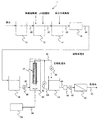
本発明の実施形態に係る水処理装置の一例の概略を図1に示し、その構成について説明する。水処理装置1は、原水槽10と、凝集分離処理手段である無機凝集反応槽12、高分子凝集反応槽14、および凝集固液分離手段としての凝集固液分離装置16と、凝集処理水槽18と、浸漬膜活性汚泥処理手段である生物反応槽20、および浸漬膜を備える浸漬膜ユニット22と、生物処理水槽24と、逆浸透膜(RO膜)を有する逆浸透膜処理手段であるRO膜分離装置26とを備える。
An example of a water treatment apparatus according to an embodiment of the present invention is schematically shown in FIG. The
図1の水処理装置1において、原水槽10の出口は原水配管28により無機凝集反応槽12の入口と、無機凝集反応槽12の出口は無機凝集水配管30により高分子凝集反応槽14の入口と、高分子凝集反応槽14の出口は高分子凝集水配管32により凝集固液分離装置16の入口と、凝集固液分離装置16の出口は凝集処理水配管34により凝集処理水槽18の入口と、それぞれ接続されている。凝集処理水槽18の出口は、ポンプ36を介して凝集処理水配管38により生物反応槽20の下部と接続されている。生物反応槽20には、浸漬膜ユニット22が設置され、浸漬膜ユニット22の浸漬膜は、吸引ポンプ40を介して生物処理水配管42により生物処理水槽24と接続されている。生物処理水槽24の出口は、フィルタ44、ポンプ46を介して生物処理水配管48により、RO膜分離装置26の入口に接続されている。RO膜分離装置26の出口には、処理水配管50が接続されている。また、生物処理水槽24の下部は、必要に応じて、逆洗手段である逆洗ポンプ52を介して逆洗配管54により生物処理水配管42の途中の吸引ポンプ40下流側に接続されていてもよい。生物反応槽20の底部には、曝気手段であるコンプレッサ56が曝気配管58により接続されている。
In the
本実施形態に係る水処理方法及び水処理装置1の動作について説明する。
The operation of the water treatment method and the
<凝集分離処理工程>
図1の水処理装置1において、現像廃液含有原水(以下、単に「原水」と呼ぶ場合がある)は、原水槽10に流入した後、原水配管28を通して無機凝集反応槽12に送液される。無機凝集反応槽12において、無機凝集剤が添加され、レジスト由来の樹脂などの無機凝集反応が行われる(無機凝集反応工程)。無機凝集反応槽12では、図示しないpH調整手段であるポンプなどによりpH調整剤が添加され、凝集分離処理におけるpHが調整されることが好ましい。このあと、無機凝集処理された無機凝集水は、無機凝集水配管30を通して高分子凝集反応槽14に送液される。高分子凝集反応槽14において、高分子凝集剤が添加され、高分子凝集反応が行われる(高分子凝集反応工程)。高分子凝集処理された高分子凝集水は、高分子凝集水配管32を通して凝集固液分離装置16に送液され、凝集固液分離装置16において、凝集固液分離処理が行われて、凝集処理水が得られる(凝集固液分離処理工程)。凝集固液分離処理工程においては、加圧浮上処理手段である加圧浮上装置により固液分離が行われることが好ましい。
<Aggregation separation process>
In the
<浸漬膜活性汚泥処理工程>
凝集処理水は、ポンプ36により凝集処理水配管38を通して、生物反応槽20に送液される。生物反応槽20には、好気性の活性汚泥が存在する。一方、生物反応槽20の底部から、コンプレッサ56からの空気が曝気配管58を通して送気されている。生物反応槽20において、活性汚泥により原水中の有機物の分解処理が行われる(浸漬膜活性汚泥処理工程)。浸漬膜ユニット22の浸漬膜は吸引ポンプ40により吸引され、固液分離が行われる(固液分離工程)。固液分離された生物処理水は、生物処理水配管42を通して、生物処理水槽24に送液される。必要に応じて、所定の間隔で、生物処理水槽24の生物処理水の少なくとも一部は逆洗水として、逆洗ポンプ52により逆洗配管54、生物処理水配管42を通して浸漬膜ユニット22の浸漬膜に送液され、浸漬膜が逆洗されてもよい。
<Immersion membrane activated sludge treatment process>
The agglomerated water is sent to the
<逆浸透膜処理工程>
生物処理水を回収、再利用する場合には、さらにポンプ46によりフィルタ44を経由して生物処理水配管48を通してRO膜分離装置26に送液され、RO膜分離装置26において、RO膜によりRO膜処理が行われる(逆浸透膜処理工程)。RO膜処理された処理水は処理水配管50を通して系外に排出される。
<Reverse osmosis membrane treatment process>
When the biologically treated water is collected and reused, the liquid is further sent to the RO
<適用可能な原水>
本実施形態において、適用可能な現像廃液含有原水のTOC濃度は、水回収向けでは例えば、2000mgC/L以下、BOD濃度は、例えば、500mg/L以下である。また、水回収向け以外では例えば、TOC濃度は1500mgC/L以下、BOD濃度は3000mg/L以下である。
<Applicable raw water>
In this embodiment, the applicable TOC concentration of developing waste liquid-containing raw water is, for example, 2000 mgC / L or less, and the BOD concentration is, for example, 500 mg / L or less for water recovery. For example, other than for water recovery, the TOC concentration is 1500 mgC / L or less and the BOD concentration is 3000 mg / L or less.
適用可能な原水は、例えば、半導体工場、液晶パネル工場、その他の工場から排出されるレジスト樹脂(通常、pH中性条件で析出、アルカリ条件では溶解している)などのSSを含む排水である。これらの排水に含有される成分の主なものとして、2−アミノエタノール、2−プロパノール、TMAH(テトラメチルアンモニウムヒドロキシド)、コリン、DMSO(ジメチルスルホキシド)、N−メチル−2−ピロリドン、酢酸、シュウ酸などの有機酸、界面活性剤などがあるが、含有成分はこれらの物質に限定されるものではない。主に、フォトレジストなどのレジストを用いる工程からのレジスト樹脂を含む現像廃液含有排水に好適である。レジスト樹脂としては、フォトレジストなどのレジストに用いられる樹脂であればよく特に制限はない。フォトレジストの種類としては露光された部分が現像液に可溶になる(エッチングされる)ポジ型フォトレジストや露光された部分が現像液に不溶になるネガ型フォトレジストがある。 Applicable raw water is, for example, wastewater containing SS such as resist resin discharged from semiconductor factories, liquid crystal panel factories, and other factories (usually precipitated under pH neutral conditions and dissolved under alkaline conditions). . The main components contained in these wastewaters include 2-aminoethanol, 2-propanol, TMAH (tetramethylammonium hydroxide), choline, DMSO (dimethylsulfoxide), N-methyl-2-pyrrolidone, acetic acid, There are organic acids such as oxalic acid and surfactants, but the components are not limited to these substances. It is suitable mainly for waste water containing a development waste liquid containing a resist resin from a process using a resist such as a photoresist. The resist resin is not particularly limited as long as it is a resin used for a resist such as a photoresist. As a kind of the photoresist, there are a positive type photoresist in which the exposed portion is soluble (etched) in the developer and a negative photoresist in which the exposed portion is insoluble in the developer.
<凝集分離処理条件>
無機凝集処理においては、通常の凝集処理に使用されるポリ塩化アルミニウム(PAC)などの無機凝集剤を用いて、50〜500mg/L程度の濃度で実施することができる。
<Aggregation separation processing conditions>
The inorganic agglomeration treatment can be performed at a concentration of about 50 to 500 mg / L using an inorganic aggregating agent such as polyaluminum chloride (PAC) used for ordinary agglomeration treatment.
高分子凝集処理においては、通常の凝集処理に使用されるアニオンポリマなどの高分子凝集剤を用いて、1〜10mg/L程度の濃度で実施することができる。 The polymer flocculation treatment can be performed at a concentration of about 1 to 10 mg / L using a polymer flocculating agent such as an anionic polymer used in ordinary flocculation treatment.
凝集処理(無機凝集反応工程、高分子凝集反応工程)におけるpHは、通常は5.5〜8.0の範囲であるが、本方法では、通常よりpHが弱酸性の5.5〜7の範囲であることが好ましく、6〜6.5の範囲であることがより好ましい。pH5.5〜7の範囲で凝集状態が良好となる傾向にある。おそらく、レジストが酸性でより析出しやすくなるためと考えられる。本範囲であれば、凝集分離処理後に活性汚泥処理のためのpH調整を再度行うのを省力することが可能となる。 The pH in the flocculation treatment (inorganic flocculation reaction step, polymer flocculation reaction step) is usually in the range of 5.5 to 8.0, but in this method, the pH is 5.5 to 7 which is slightly less acidic than usual. The range is preferable, and the range of 6 to 6.5 is more preferable. The aggregation state tends to be good in the range of pH 5.5-7. This is probably because the resist is acidic and more likely to precipitate. If it is this range, it will become possible to save labor to perform pH adjustment for activated sludge processing again after coagulation separation processing.
pH調整剤としては、塩酸などの酸、または苛性ソーダなどのアルカリを用いることができる。 As the pH adjusting agent, an acid such as hydrochloric acid or an alkali such as caustic soda can be used.
凝集処理後の凝集固液分離手段としては、沈殿池、加圧浮上処理、膜処理などが使用できるが、経済性、凝集状態などの点から、加圧浮上が好ましい。 As the agglomerated solid-liquid separation means after the agglomeration treatment, a sedimentation basin, a pressurized flotation treatment, a membrane treatment, and the like can be used.
<浸漬膜活性汚泥処理条件>
浸漬膜活性汚泥処理における生物反応槽20の処理条件としては、汚泥濃度が10,000mg/L以下、好ましくは、3,000〜8,000mg/Lの範囲、汚泥粘度が60mPa・s以下、好ましくは、50mPa・s以下、生物反応槽20の負荷が1.5kgBOD/m3/day以下、好ましくは0.4〜1.0kgBOD/m3/dayの範囲で運転することが好ましい。
<Immersion membrane activated sludge treatment conditions>
As the treatment conditions of the
汚泥濃度が10,000mg/Lを超えると汚泥の粘度が急激に上昇し、浸漬膜が目詰まる場合があり、3,000mg/L未満であると汚泥当たりのBOD負荷が高くなり、処理水質が悪化する場合がある。汚泥粘度が60mPa・sを超えると汚泥の粘度が急激に上昇し、浸漬膜が目詰まる場合がある。また、生物反応槽20の負荷が1.5kgBOD/m3/dayを超えると処理水質の悪化と浸漬膜の目詰まりが起こる場合があり、0.4kgBOD/m3/day未満であると浸漬膜の目詰まりが起き、また生物反応槽が大きく不経済となる場合がある。
If the sludge concentration exceeds 10,000 mg / L, the viscosity of the sludge increases rapidly and the immersion membrane may be clogged. If it is less than 3,000 mg / L, the BOD load per sludge increases and the quality of the treated water It may get worse. If the sludge viscosity exceeds 60 mPa · s, the viscosity of the sludge increases rapidly and the immersion film may be clogged. Moreover, when the load of the
生物反応槽20における滞留時間は、1時間〜24時間の範囲であり、2〜5時間の範囲が好ましい。滞留時間が1時間未満であると処理を十分に行うことができない。24時間を超えると処理コストが増大する。また、フロックが分散化してしまう。
The residence time in the
生物反応槽20における汚泥負荷(BOD−SS負荷)については、0.005〜0.15kgBOD/SS/dayの範囲が好ましい。汚泥負荷が0.005kgBOD/SS/day未満であると低負荷により汚泥が分散状態となり浸漬膜が目詰まる場合があり、0.15kgBOD/SS/dayを超えると高負荷により処理水質が悪化し、また菌の代謝産物の増加により浸漬膜が目詰まる場合がある。
About the sludge load (BOD-SS load) in the
生物反応槽20における液のpHは、5.5〜7の範囲、特に5.5〜6.5の範囲となるように調整することが好ましい。pH5.5〜7の範囲であれば、凝集処理水に残留したレジストを析出しやすくして汚泥に取り込ませることができ、かつ生物処理が可能である。pHが5.5未満や7を超えると生物処理性能が悪化する場合がある。前述のように、凝集処理におけるpHを5.5〜7の範囲に調整することにより、生物反応槽20における液のpHが5.5〜7の範囲に保たれるが、必要に応じて、pH調整剤を添加してpH調整を行ってもよい。
It is preferable to adjust the pH of the liquid in the
生物反応槽20におけるDO(溶存酸素)濃度は、0.5mg/L以上、特に1.5〜3.5mg/Lの範囲であることが好ましい。DO濃度が0.5mg/L未満であると生物処理性能が悪化する場合があり、3.5mg/Lを超えるとフロックが分散化してしまい、また処理コストが増大して不経済となる場合がある。
The DO (dissolved oxygen) concentration in the
生物反応槽20における栄養源としては、微生物が有機物を分解し、増殖していくためには、窒素、リンのほか、ナトリウム、カリウム、カルシウム、マグネシウムなどのアルカリ金属類や鉄、マンガン、亜鉛などの金属類といった微量金属類が必要となる。窒素源としては、外部から尿素、アンモニア塩などを添加することができる。リン源としては、外部からリン酸塩、リン酸を添加することができる。また、窒素源・リン源としては、原水中に十分量含まれていれば外部から添加する必要はなく、また、窒素・リンを含む他の排水を有機物含有原水に添加することでも対応することができる。微量金属類は、半導体工場や液晶パネル工場での有機物含有原水では、不足することが多い。このため、水道水、工業用水などの微量金属類を含む水を導入する、微量元素を含む製剤を添加するなどの方法で補給することもできる。
As nutrient sources in the
<浸漬膜>
浸漬膜は生物反応槽20内に浸漬し、浸漬膜の吸引ろ過によって生物処理水を得ることができるが、生物反応槽20の後段に別途、膜分離槽を設けて、そこに浸漬膜を浸漬することもできる。本実施形態では、定期的に逆洗可能な形態、代表的には中空糸膜、管状膜などを用いることが好ましいが、平膜などを用いることもできる。平膜では端部破損のおそれがあるため逆洗が困難である。浸漬膜としては、精密ろ過膜あるいは限外ろ過膜を用いることができる。浸漬膜の材質は、例えばポリフッ化ビニリデン(PVDF)、ポリテトラフルオロエチレン(PTFE)などのフッ素系樹脂、ポリエチレン(PE)、ポリプロピレン(PP)などが適用でき、膜の詰まりにくさなどの点からPVDFが好ましい。膜の孔径は0.4μm以下、特に0.1μm以下が好ましい。膜の透過流速は、0.1〜0.8m/hr程度で運転することができ、より好ましくは0.2〜0.6m/hrの範囲で運転することができる。
<Immersion film>
The immersion membrane can be immersed in the
<RO膜>
RO膜としては、ポリエーテルアミド複合膜、ポリビニルアルコール複合膜、芳香族ポリアミド膜などが使用でき、界面活性剤や微量有機物による汚染を受けにくいとされている膜表面の荷電を中性とした膜(例えば、日東電工製LF−10)や、従来の低圧RO膜に比べて低い操作圧力で運転できる超低圧型の膜(例えば、日東電工製ES−10)などの適用が好ましい。これらのRO膜のモジュール形状は、スパイラル型、中空糸型、管状型など、いずれの形状でも使用できる。
<RO membrane>
As RO membranes, polyether amide composite membranes, polyvinyl alcohol composite membranes, aromatic polyamide membranes, etc. can be used, membranes that are neutrally charged on the surface of membranes that are considered to be less susceptible to contamination by surfactants and trace organics (For example, LF-10 manufactured by Nitto Denko) and ultra-low pressure type membranes (for example, ES-10 manufactured by Nitto Denko) that can be operated at a lower operating pressure than conventional low-pressure RO membranes are preferable. The module shape of these RO membranes can be any shape such as a spiral type, a hollow fiber type, and a tubular type.
また、現像廃液含有原水が、非イオン性界面活性剤、ポリエチレングリコールなどを含む場合、RO膜が目詰まりやすいことから、そのような場合には、RO膜分離装置26の前段側(例えば、フィルタ44の前段)に活性炭処理手段である活性炭処理装置を設置することが好ましい。また、RO膜の前処理として孔径10μm程度のフィルタ44を設置することが好ましい。
Further, when the development waste liquid-containing raw water contains a nonionic surfactant, polyethylene glycol, etc., the RO membrane is likely to be clogged. In such a case, the upstream side of the RO membrane separation device 26 (for example, a filter) It is preferable to install an activated carbon treatment apparatus, which is an activated carbon treatment means, in the preceding stage of 44. Further, it is preferable to install a
カルシウムなどの無機分でスケールを生じる可能性がある場合、RO膜分離装置26に分散剤の添加手段、または軟化装置を設置することが好ましい。さらに、長期的な運転で微生物起因のスライム発生による目詰まりを防止することを目的として、スライムコントロール剤(イソチアゾリン系、有機臭素系など)の添加、硫酸などによる酸ショック付与、アルカリ運転(pH9.5以上)などを行うことができる。
In the case where there is a possibility that scale is generated due to an inorganic component such as calcium, it is preferable to install a dispersing agent adding means or a softening device in the RO
処理水は、工場などの冷却水、または製造用水、純水、超純水などとして再利用することができる。 The treated water can be reused as cooling water for factories or the like, water for production, pure water, ultrapure water, or the like.
水回収率は、高い方が経済的に好ましいが、安定運転を可能とする有機性排水回収系としては、50〜90%、好ましくは65〜75%で運転することが好ましい。 A higher water recovery rate is economically preferable, but it is preferable to operate at 50 to 90%, preferably 65 to 75%, as an organic wastewater recovery system that enables stable operation.
以上のように、本発明者らは、近年需要が増加している液晶パネル工場などの現像廃液含有原水の処理、回収に浸漬膜活性汚泥を適用する場合に、非常に短期で吸引圧力が発生するため、実用化できないという問題を明確にした。これに対して、本実施形態に係る水処理方法および水処理装置により、凝集分離処理後に浸漬膜活性汚泥処理を実施することにより、運転管理、薬品洗浄等によるコストの増加を解決して、運転管理が容易で、現像廃液含有原水の浸漬膜活性汚泥処理の安定運転、および後段のRO処理も含めた安定運転が可能となる。したがって、特にRO膜を組み合わせた排水回収システムにおいて有効な方法となる。今後、現像廃液含有原水の水処理、回収は、国内、海外も含めて、水資源確保、排水放流の観点から非常に望まれており、本実施形態に係る水処理方法および水処理装置は非常に有用と考えられる。 As described above, the present inventors generate suction pressure in a very short time when applying submerged membrane activated sludge for treatment and recovery of raw water containing developer waste liquid such as liquid crystal panel factories, for which demand is increasing in recent years. Therefore, the problem that it cannot be put into practical use was clarified. On the other hand, the water treatment method and the water treatment apparatus according to the present embodiment perform the immersion membrane activated sludge treatment after the coagulation separation treatment, thereby solving the increase in cost due to operation management, chemical cleaning, etc. Management is easy, and stable operation of the immersion membrane activated sludge treatment of the developing waste liquid-containing raw water and stable operation including the subsequent RO treatment are possible. Therefore, it becomes an effective method especially in the wastewater recovery system combined with the RO membrane. In the future, water treatment and recovery of raw water containing developer wastewater will be highly desired from the viewpoint of securing water resources and draining water, including in Japan and overseas, and the water treatment method and water treatment apparatus according to this embodiment will be very It is considered useful.
以下、実施例および比較例を挙げ、本発明をより具体的に詳細に説明するが、本発明は、以下の実施例に限定されるものではない。 Hereinafter, although an example and a comparative example are given and the present invention is explained more concretely in detail, the present invention is not limited to the following examples.
(実施例1、比較例1,2)
現像廃液含有原水向けの浸漬膜適用評価を現場の実排水、模擬排水を用いて実験した。テストには、PVDF製中空糸型浸漬膜を用いて、浸漬膜の吸引圧力、処理水質、後段RO膜の目詰まりについての評価を実施した。用いた実験装置を図2に示す。
(Example 1, Comparative Examples 1 and 2)
An evaluation of immersion membrane application for raw water containing developer wastewater was conducted using actual wastewater and simulated wastewater. For the test, PVDF hollow fiber type immersion membranes were used to evaluate the suction pressure of the immersion membrane, the quality of the treated water, and clogging of the downstream RO membrane. The experimental apparatus used is shown in FIG.
<通水条件>
原水:電子産業工場の模擬排水、および実排水 TOC濃度80mgC/L(原水BOD濃度:200mg/L)
実施例1:実排水を以下の条件で凝集処理後、SSを加圧浮上により分離した水を使用
(凝集条件)原水にPAC100mg/L添加後、pHを6.0±0.2に調整し、アニオンポリマ(オルガノ(株)製、OA−23)1mg/L添加して凝集
比較例1:実排水と同じ基質、組成の模擬排水(レジスト由来のSSは含まず)
比較例2:実排水(原水のSS30mg/L)
通水流量:17L/day
<Water flow conditions>
Raw water: Simulated wastewater from electronic industry factory, and actual wastewater TOC concentration 80mgC / L (Rawwater BOD concentration: 200mg / L)
Example 1: Use the water from which the actual wastewater was agglomerated under the following conditions and then separated SS by pressurized flotation. (Agglomeration conditions) After adding PAC 100 mg / L to the raw water, the pH was adjusted to 6.0 ± 0.2. Anion polymer (manufactured by Organo Co., Ltd., OA-23) 1 mg / L added to agglomerate Comparative Example 1: Simulated wastewater having the same substrate and composition as actual wastewater (not including resist-derived SS)
Comparative Example 2: Actual drainage (SS30mg / L of raw water)
Water flow rate: 17L / day
<実験装置>
生物反応槽(MBR槽)、浸漬膜ユニット、RO膜は、以下のような実験装置を用いて実施した。
[生物反応槽]
生物反応槽容量:1L
膜分離槽容量:2.5L
pH:6前後で制御
水温:20〜22℃
滞留時間:4.9時間
汚泥濃度(MLSS):7,000〜8,000mg/L
BOD−SS負荷:0.10〜0.12kgBOD/kgSS/day
DO:1〜2mgO/L
送気風量:0.5L/min
[浸漬膜ユニット]
PVDF製中空糸型浸漬膜(旭化成製、孔径0.1μm)
浸漬膜のフラックス:0.6m/day
[RO膜]
膜:日東電工製 LF−10 水回収率70%
<Experimental equipment>
The biological reaction tank (MBR tank), the immersion membrane unit, and the RO membrane were implemented using the following experimental apparatus.
[Bioreaction tank]
Biological reaction tank capacity: 1L
Membrane separation tank capacity: 2.5L
pH: Control around 6 Water temperature: 20-22 ° C
Residence time: 4.9 hours Sludge concentration (MLSS): 7,000 to 8,000 mg / L
BOD-SS load: 0.10 to 0.12 kg BOD / kgSS / day
DO: 1-2 mg O / L
Air supply volume: 0.5L / min
[Immersion membrane unit]
PVDF hollow fiber type immersion membrane (Asahi Kasei, pore size 0.1 μm)
Immersion film flux: 0.6 m / day
[RO membrane]
Membrane: Nitto Denko LF-10 70% water recovery
<結果>
図3に各条件で実施した際の浸漬膜の吸引圧力を示す。比較例1と比較例2との結果から、溶存している基質は同等であるにも関わらず、膜の吸引圧力の上昇が顕著に異なることを見出した。実排水を用いた比較例2では、通常実用化されているフラックス0.6m/dayで3日で薬品洗浄を必要とする差圧30kPaに達してしまい、実用化困難であることが判明した。これに対し、実排水中に含有されるSSを凝集処理した水を用いた実施例1では吸引圧力の上昇が抑制され、安定することを確認した。
<Result>
FIG. 3 shows the suction pressure of the submerged membrane when implemented under each condition. From the results of Comparative Example 1 and Comparative Example 2, it was found that although the dissolved substrates were equivalent, the increase in the suction pressure of the membrane was significantly different. In Comparative Example 2 using actual waste water, it was found that it was difficult to put it to practical use because it reached a differential pressure of 30 kPa, which required chemical cleaning in 3 days, with a flux of 0.6 m / day that was normally put into practical use. On the other hand, in Example 1 using the water which carried out the aggregation process of SS contained in a real waste_water | drain, the raise of the suction pressure was suppressed and it confirmed that it stabilized.
図4に、実施例1で用いた実排水と凝集分離後の凝集処理水を波長スキャンした吸光度の結果を示す。レジストに特徴的な波長290nm付近のピーク(特開2001?212596号公報参照)が原水に見られるが、凝集処理後に大きく減じていることがわかる。なお、吸光度の測定は、樹脂を溶解させるために、pH12に調整してから行った。 FIG. 4 shows the results of absorbance obtained by wavelength scanning of the actual waste water used in Example 1 and the agglomerated water after agglomeration separation. A peak near a wavelength of 290 nm (see Japanese Patent Application Laid-Open No. 2001-212596) characteristic of the resist is seen in the raw water, but it can be seen that it is greatly reduced after the aggregation treatment. The absorbance was measured after adjusting the pH to 12 in order to dissolve the resin.
この時の実施例1と比較例2の各条件での処理水質に関してはどの系でも良好な水質であった。 At this time, the quality of the treated water under each condition of Example 1 and Comparative Example 2 was good in any system.
また、実施例1の処理水のRO膜への通水試験も実施し、処理水質は0.9mgC/Lと良好であり、RO膜のフラックスも安定することを確認し、実施例1の方法が特に電子産業工場の排水回収に有効であることを確認した。 In addition, a water flow test of the treated water of Example 1 to the RO membrane was also conducted, and it was confirmed that the quality of the treated water was 0.9 mg C / L and the RO membrane flux was stable. Has been confirmed to be particularly effective in collecting wastewater from electronic industry factories.
このように、電子産業などで排出される排水を安定して水回収することが可能となった。 As described above, it has become possible to stably recover water discharged from the electronics industry.
1 水処理装置、10 原水槽、12 無機凝集反応槽、14 高分子凝集反応槽、16 凝集固液分離装置、18 凝集処理水槽、20 生物反応槽、22 浸漬膜ユニット、24 生物処理水槽、26 RO膜分離装置、28 原水配管、30 無機凝集水配管、32 高分子凝集水配管、34,38 凝集処理水配管、36,46 ポンプ、40 吸引ポンプ、42,48 生物処理水配管、44 フィルタ、50 処理水配管、52 逆洗ポンプ、54 逆洗配管、56 コンプレッサ、58 曝気配管。
DESCRIPTION OF
Claims (8)
前記浸漬膜活性汚泥処理工程の前に、前記現像廃液含有原水のpHを5.5〜7の範囲に調整し、無機凝集剤を添加した後に、高分子凝集剤を添加する凝集分離処理工程を含むことを特徴とする水処理方法。 It is a water treatment method including an immersion sludge activated sludge treatment step in which a development waste liquid-containing raw water containing a resist resin is subjected to activated sludge treatment using an immersion membrane,
Before the immersion membrane activated sludge treatment step, adjusting the pH of the developing waste liquid-containing raw water to a range of 5.5 to 7, adding an inorganic flocculant and then adding a polymer flocculant ; A water treatment method comprising:
前記浸漬膜活性汚泥処理工程における負荷を0.4〜1.5kgBOD/m3/dayの範囲とすることを特徴とする水処理方法。 The water treatment method according to claim 1,
The water treatment method characterized by making the load in the said immersion membrane activated sludge process process into the range of 0.4-1.5kgBOD / m < 3 > / day.
前記浸漬膜活性汚泥処理工程における汚泥濃度を3,000〜10,000mg/Lの範囲とすることを特徴とする水処理方法。 The water treatment method according to claim 1 or 2,
The water treatment method characterized by making the sludge density | concentration in the said immersion membrane activated sludge process process into the range of 3,000-10,000 mg / L.
逆浸透膜を用いて、前記活性汚泥処理を行った生物処理水の分離処理を行う逆浸透膜処理工程をさらに含むことを特徴とする水処理方法。 The water treatment method according to any one of claims 1 to 3,
The water treatment method characterized by further including the reverse osmosis membrane process process which performs the separation process of the biologically treated water which performed the said activated sludge process using a reverse osmosis membrane.
前記浸漬膜活性汚泥処理手段の前段に、前記現像廃液含有原水のpHを5.5〜7の範囲に調整し、無機凝集剤を添加した後に、高分子凝集剤を添加する凝集分離処理手段を備えることを特徴とする水処理装置。 A water treatment apparatus provided with a submerged membrane activated sludge treatment means for performing development sludge treatment using a submerged membrane with a development waste liquid-containing raw water containing a resist resin ,
A flocculation separation treatment means for adjusting the pH of the developing waste liquid-containing raw water to a range of 5.5 to 7 and adding an inorganic flocculant and then adding a polymer flocculant before the immersion membrane activated sludge treatment means. A water treatment apparatus comprising:
前記浸漬膜活性汚泥処理手段における負荷を0.4〜1.5kgBOD/m3/dayの範囲とすることを特徴とする水処理装置。 The water treatment device according to claim 5,
A water treatment apparatus characterized in that the load in the submerged membrane activated sludge treatment means is in the range of 0.4 to 1.5 kg BOD / m 3 / day.
前記浸漬膜活性汚泥処理手段における汚泥濃度を3,000〜10,000mg/Lの範囲とすることを特徴とする水処理装置。 The water treatment device according to claim 5 or 6,
A water treatment apparatus characterized in that the sludge concentration in the submerged membrane activated sludge treatment means is in the range of 3,000 to 10,000 mg / L.
逆浸透膜を用いて、前記活性汚泥処理を行った生物処理水の分離処理を行う逆浸透膜処理手段をさらに備えることを特徴とする水処理装置。 The water treatment apparatus according to any one of claims 5 to 7,
A water treatment apparatus further comprising reverse osmosis membrane treatment means for separating biologically treated water subjected to the activated sludge treatment using a reverse osmosis membrane.
Priority Applications (1)
| Application Number | Priority Date | Filing Date | Title |
|---|---|---|---|
| JP2008054212A JP5106182B2 (en) | 2008-03-05 | 2008-03-05 | Water treatment method and water treatment apparatus |
Applications Claiming Priority (1)
| Application Number | Priority Date | Filing Date | Title |
|---|---|---|---|
| JP2008054212A JP5106182B2 (en) | 2008-03-05 | 2008-03-05 | Water treatment method and water treatment apparatus |
Publications (2)
| Publication Number | Publication Date |
|---|---|
| JP2009208012A JP2009208012A (en) | 2009-09-17 |
| JP5106182B2 true JP5106182B2 (en) | 2012-12-26 |
Family
ID=41181686
Family Applications (1)
| Application Number | Title | Priority Date | Filing Date |
|---|---|---|---|
| JP2008054212A Active JP5106182B2 (en) | 2008-03-05 | 2008-03-05 | Water treatment method and water treatment apparatus |
Country Status (1)
| Country | Link |
|---|---|
| JP (1) | JP5106182B2 (en) |
Families Citing this family (3)
| Publication number | Priority date | Publication date | Assignee | Title |
|---|---|---|---|---|
| JP5828327B2 (en) * | 2013-02-13 | 2015-12-02 | 栗田工業株式会社 | Method for processing development wastewater in color filter manufacturing process |
| JP2015054273A (en) * | 2013-09-11 | 2015-03-23 | 株式会社日立製作所 | Desalination system |
| CN105585115A (en) * | 2016-01-14 | 2016-05-18 | 南京大学 | Method for reducing membrane pollution of high-salt wastewater MBR (membrane bioreactor) treatment system |
Family Cites Families (12)
| Publication number | Priority date | Publication date | Assignee | Title |
|---|---|---|---|---|
| JPH08235B2 (en) * | 1987-03-31 | 1996-01-10 | 三菱化学株式会社 | Development waste treatment method |
| JPH0659478B2 (en) * | 1990-02-08 | 1994-08-10 | 株式会社クボタ | Organic wastewater treatment method |
| JPH07155759A (en) * | 1993-12-08 | 1995-06-20 | Kubota Corp | Waste water treating device |
| JPH07222994A (en) * | 1994-02-16 | 1995-08-22 | Kubota Corp | Organic waste water treatment method |
| JP2000237760A (en) * | 1999-02-23 | 2000-09-05 | Japan Organo Co Ltd | Organic waste water treatment |
| JP4101539B2 (en) * | 2002-03-18 | 2008-06-18 | オルガノ株式会社 | Wastewater treatment equipment |
| JP2004358345A (en) * | 2003-06-04 | 2004-12-24 | Jfe Engineering Kk | Phosphorus-containing organic sewage treatment apparatus |
| JP2006015236A (en) * | 2004-07-01 | 2006-01-19 | Toray Ind Inc | Apparatus and method for preparing regenerated water |
| JP4743388B2 (en) * | 2005-03-18 | 2011-08-10 | 栗田工業株式会社 | Disposal method of waste water containing photoresist |
| JP4696713B2 (en) * | 2005-06-17 | 2011-06-08 | 富士ゼロックス株式会社 | Wastewater treatment method |
| JP2007029825A (en) * | 2005-07-25 | 2007-02-08 | Daiki Ataka Engineering Co Ltd | Apparatus for treating waste water and method for treating waste water using the apparatus |
| JP5017854B2 (en) * | 2005-12-14 | 2012-09-05 | 栗田工業株式会社 | Apparatus and method for treating wastewater containing organic matter |
-
2008
- 2008-03-05 JP JP2008054212A patent/JP5106182B2/en active Active
Also Published As
| Publication number | Publication date |
|---|---|
| JP2009208012A (en) | 2009-09-17 |
Similar Documents
| Publication | Publication Date | Title |
|---|---|---|
| TWI494281B (en) | Apparatus for treating organic waste water | |
| EP2537810B1 (en) | Method for generating fresh water and method for desalinating sea water | |
| JP5315587B2 (en) | Apparatus and method for treating wastewater containing organic matter | |
| JP4862361B2 (en) | Waste water treatment apparatus and waste water treatment method | |
| JP2008173534A (en) | Water treatment method and water treatment apparatus | |
| JP2011088053A (en) | Equipment and method for desalination treatment | |
| JP4997724B2 (en) | Organic wastewater treatment method | |
| KR20070063423A (en) | Apparatus and method for treatment of organic substance-containing wastewater | |
| CN208917033U (en) | Pre-treatment waste water treatment system | |
| JP2011173040A (en) | Waste water treatment method and apparatus | |
| JPWO2014007301A1 (en) | Fresh water generation method and fresh water generation apparatus | |
| JP5106182B2 (en) | Water treatment method and water treatment apparatus | |
| CN110540318A (en) | Sewage recovery treatment system and treatment process | |
| WO2011136043A1 (en) | Wastewater treatment device and wastewater treatment method | |
| JP2009172551A (en) | Manufacturing method of recycled water | |
| Plevri et al. | Promoting on-site urban wastewater reuse through MBR-RO treatment | |
| KR20040002594A (en) | Liquid treatment method and apparatus | |
| JP2009189943A (en) | Water treatment method and apparatus | |
| JP4899565B2 (en) | Water treatment apparatus and water treatment method | |
| JP2006095425A (en) | Method for purifying biological treatment water-containing water of waste water and apparatus for purifying the same | |
| JP2006281174A (en) | Method, apparatus and system for recycling wastewater | |
| JPH11239789A (en) | Advanced method for water treatment | |
| WO2016136957A1 (en) | Method for treating water containing organic material, and device for treating water containing organic material | |
| JP4844445B2 (en) | Aggregation method | |
| JP2016093789A (en) | Water treatment method and water treatment system |
Legal Events
| Date | Code | Title | Description |
|---|---|---|---|
| A621 | Written request for application examination |
Free format text: JAPANESE INTERMEDIATE CODE: A621 Effective date: 20100917 |
|
| A977 | Report on retrieval |
Free format text: JAPANESE INTERMEDIATE CODE: A971007 Effective date: 20110706 |
|
| A131 | Notification of reasons for refusal |
Free format text: JAPANESE INTERMEDIATE CODE: A131 Effective date: 20110802 |
|
| A521 | Request for written amendment filed |
Free format text: JAPANESE INTERMEDIATE CODE: A523 Effective date: 20110929 |
|
| A131 | Notification of reasons for refusal |
Free format text: JAPANESE INTERMEDIATE CODE: A131 Effective date: 20120612 |
|
| A521 | Request for written amendment filed |
Free format text: JAPANESE INTERMEDIATE CODE: A523 Effective date: 20120731 |
|
| TRDD | Decision of grant or rejection written | ||
| A01 | Written decision to grant a patent or to grant a registration (utility model) |
Free format text: JAPANESE INTERMEDIATE CODE: A01 Effective date: 20120925 |
|
| A01 | Written decision to grant a patent or to grant a registration (utility model) |
Free format text: JAPANESE INTERMEDIATE CODE: A01 |
|
| A61 | First payment of annual fees (during grant procedure) |
Free format text: JAPANESE INTERMEDIATE CODE: A61 Effective date: 20121002 |
|
| R150 | Certificate of patent or registration of utility model |
Ref document number: 5106182 Country of ref document: JP Free format text: JAPANESE INTERMEDIATE CODE: R150 Free format text: JAPANESE INTERMEDIATE CODE: R150 |
|
| FPAY | Renewal fee payment (event date is renewal date of database) |
Free format text: PAYMENT UNTIL: 20151012 Year of fee payment: 3 |
|
| R250 | Receipt of annual fees |
Free format text: JAPANESE INTERMEDIATE CODE: R250 |
|
| R250 | Receipt of annual fees |
Free format text: JAPANESE INTERMEDIATE CODE: R250 |
|
| R250 | Receipt of annual fees |
Free format text: JAPANESE INTERMEDIATE CODE: R250 |
|
| R250 | Receipt of annual fees |
Free format text: JAPANESE INTERMEDIATE CODE: R250 |
|
| R250 | Receipt of annual fees |
Free format text: JAPANESE INTERMEDIATE CODE: R250 |
|
| R250 | Receipt of annual fees |
Free format text: JAPANESE INTERMEDIATE CODE: R250 |
|
| R250 | Receipt of annual fees |
Free format text: JAPANESE INTERMEDIATE CODE: R250 |
|
| R250 | Receipt of annual fees |
Free format text: JAPANESE INTERMEDIATE CODE: R250 |
|
| R250 | Receipt of annual fees |
Free format text: JAPANESE INTERMEDIATE CODE: R250 |