JP5104096B2 - 3D image display apparatus and 3D image display method - Google Patents
3D image display apparatus and 3D image display method Download PDFInfo
- Publication number
- JP5104096B2 JP5104096B2 JP2007195012A JP2007195012A JP5104096B2 JP 5104096 B2 JP5104096 B2 JP 5104096B2 JP 2007195012 A JP2007195012 A JP 2007195012A JP 2007195012 A JP2007195012 A JP 2007195012A JP 5104096 B2 JP5104096 B2 JP 5104096B2
- Authority
- JP
- Japan
- Prior art keywords
- eye
- image
- shutter
- image display
- scanning
- Prior art date
- Legal status (The legal status is an assumption and is not a legal conclusion. Google has not performed a legal analysis and makes no representation as to the accuracy of the status listed.)
- Expired - Fee Related
Links
Images


Classifications
-
- H—ELECTRICITY
- H04—ELECTRIC COMMUNICATION TECHNIQUE
- H04N—PICTORIAL COMMUNICATION, e.g. TELEVISION
- H04N2213/00—Details of stereoscopic systems
- H04N2213/008—Aspects relating to glasses for viewing stereoscopic images
Landscapes
- Stereoscopic And Panoramic Photography (AREA)
- Liquid Crystal (AREA)
- Testing, Inspecting, Measuring Of Stereoscopic Televisions And Televisions (AREA)
Description
本発明は、立体映像表示装置及び立体映像表示方法に関し、特に、電子シャッターを用いた立体映像表示装置及び立体映像表示方法に関するものである。 The present invention relates to a stereoscopic video display device and a stereoscopic video display method, and more particularly to a stereoscopic video display device and a stereoscopic video display method using an electronic shutter.
従来から、立体映像を表現する技術については種々の試みがなされており、写真、映画及びテレビジョン等の画像を扱う多くの分野で、立体映像に関する画像表示方法が研究され、実用化されてきている。 Conventionally, various attempts have been made for techniques for expressing stereoscopic images, and image display methods relating to stereoscopic images have been studied and put into practical use in many fields that handle images such as photographs, movies, and televisions. Yes.
この立体映像の画像表示方法としては、メガネ方式と無メガネ方式とに大別されるが、いずれの方式においても、視差のある画像を観察者の左右の眼にそれぞれ分離して入射させ、立体映像として見ることができるものである。 Three-dimensional image display methods are roughly classified into a glasses method and a no-glasses method. In either method, an image with parallax is separately incident on the left and right eyes of an observer, and a stereoscopic image is displayed. It can be seen as a video.
メガネ方式の方法として、特許文献1などに開示されている偏光メガネを用いる方法と、特許文献2などに開示されているシャッターメガネを用いる方法が知られている。
As a glasses method, a method using polarized glasses disclosed in
上記の偏光メガネ方式の立体映像表示装置は、例えば、液晶パネル部と、その前面に取り付けられ、偏光方向の変換用の分割波長板(1/2波長板)が画素列の1水平ライン置きに設けられた分割波長板フィルターとを有する。例えば、液晶パネル部からの画像光は、偶数ラインにおいては偏光方向が変換されずにそのまま出射され、奇数ラインにおいては分割波長板フィルターの作用により偶数ラインからの直線偏光と直交する方向に変換されて出射される。例えば、右眼用の画像光が偶数ラインで、左眼用の画像光が奇数ラインで再生されるものとする。 The polarized glasses-type stereoscopic image display device described above is attached to, for example, a liquid crystal panel unit and the front surface thereof, and a divided wavelength plate (1/2 wavelength plate) for changing the polarization direction is arranged every horizontal line of a pixel row. And a divided wavelength plate filter provided. For example, the image light from the liquid crystal panel is emitted as it is without changing the polarization direction in the even lines, and is converted into a direction orthogonal to the linearly polarized light from the even lines by the action of the divided wavelength plate filter in the odd lines. Are emitted. For example, it is assumed that the image light for the right eye is reproduced with even lines and the image light for the left eye is reproduced with odd lines.
例えば、上記のように出射される画像光は、互いに直交する偏光角を有する偏光板が右眼用と左眼用に配置されてなる、いわゆる偏光メガネを介して観察者により観察される。偏光メガネを用いることで、上記の偶数ラインで再生された右眼用の画像光が観察者の右眼に入射し、奇数ラインで再生された左眼用の画像光が観察者の左眼に入射する。
このようにして、偏光メガネを介して左右の画像を観察することにより立体映像を観察することができる。
For example, the image light emitted as described above is observed by an observer through so-called polarizing glasses in which polarizing plates having polarization angles orthogonal to each other are arranged for the right eye and the left eye. By using polarized glasses, the image light for the right eye reproduced by the even line is incident on the observer's right eye, and the image light for the left eye reproduced by the odd line is applied to the observer's left eye. Incident.
In this way, a stereoscopic image can be observed by observing the left and right images through the polarizing glasses.
また、上記のシャッターメガネ方式の立体映像表示装置は、例えば、画像表示部において、右眼用画像信号と左眼用画像信号が1フレームごとに交互に供給され、表示面において右眼用画像と左眼用画像が1フレームごとに交互に再生される。
上記の画像は、例えば、液晶などからなる交互に開閉するシャッターが右眼用と左眼用に配置されてなる、いわゆるシャッターメガネを介して観察者により観察される。シャッターメガネを用いることで、上記の右眼用画像が観察者の右眼で、左眼用画像が左眼で観察され、立体映像を観察することができる。
液晶からなるシャッターメガネは、例えば、直線偏光フィルターを備えた液晶パネルからなり、液晶パネルの駆動により光を透過あるいは不透過とする。
In the shutter glasses type stereoscopic image display device, for example, in the image display unit, the right-eye image signal and the left-eye image signal are alternately supplied for each frame, and the right-eye image is displayed on the display surface. The left-eye image is reproduced alternately every frame.
The above-described image is observed by an observer through so-called shutter glasses in which shutters that are alternately opened and closed, such as liquid crystal, are arranged for the right eye and the left eye. By using the shutter glasses, the image for the right eye is observed with the right eye of the observer, the image for the left eye is observed with the left eye, and a stereoscopic image can be observed.
The shutter glasses made of liquid crystal are composed of, for example, a liquid crystal panel provided with a linear polarizing filter, and light is transmitted or not transmitted by driving the liquid crystal panel.
図15は、上記のシャッターメガネ方式の立体映像表示装置の駆動タイミングチャートである。
例えば、画像表示部において、120fps(周期8.3ms)のフレームレートで動画が表示される。表示フレームは、第1フレームF1、第2フレームF2、・・の各フレームとブランキング期間Bのタイミングを示す。
FIG. 15 is a drive timing chart of the above-described shutter glasses type stereoscopic image display apparatus.
For example, in the image display unit, a moving image is displayed at a frame rate of 120 fps (period 8.3 ms). The display frame indicates the timing of each of the first frame F1, the second frame F2,.
ここで、例えば奇数フレーム(第1フレームF1、第3フレームF3、・・)が左眼用画像であり、偶数フレーム(第2フレームF2、第4フレームF4、・・)が右眼用画像であるとすると、左眼用シャッターの透過率TLは奇数フレームで100%、偶数フレームで0%となり、一方右眼用シャッターの透過率TRは奇数フレームで0%、偶数フレームで100%となるように、表示フレームのタイミングに合わせて透過率が変化される。例えば液晶シャッターを用いた場合、透過率を0%から100%に(あるいは100%から0%に)変化させるのに1回の2ms程度の時間を要する場合、各フレームの前後に配置されるブランキング期間Bを2ms程度に設定して、ブランキング期間B中に透過率変化が完了するように設計する必要がある。
上記のようにして、奇数フレームにおいては左眼用画像が観察者の左眼で観察され、偶数フレームにおいては右眼用画像が右眼で観察され、立体映像を観察することができる。
Here, for example, odd frames (first frame F1, third frame F3,...) Are images for the left eye, and even frames (second frame F2, fourth frames F4,...) Are images for the right eye. When present, 100% transmission T L is odd frame of the shutter for the left eye, 0% in the even frame, whereas the transmittance of the right-eye shutter T R is 0% in the odd frame, and 100% even frame Thus, the transmittance is changed in accordance with the timing of the display frame. For example, when a liquid crystal shutter is used, it takes about 2 ms to change the transmittance from 0% to 100% (or from 100% to 0%). It is necessary to set the ranking period B to about 2 ms so that the transmittance change is completed during the blanking period B.
As described above, the left-eye image is observed with the left eye of the observer in the odd-numbered frame, and the right-eye image is observed with the right eye in the even-numbered frame, so that a stereoscopic image can be observed.
例えば、画像表示装置全般において、表示される画像の画質を向上することが求められている。このためには、特許文献3に説明されているように、1秒間に画面が更新される回数を示す値である、フレームレートを高くすることが必要である。
例えば、GLV(grating light valve)と称せられる1次元変調光素子を用いて1次元の表示光をスキャンすることにより画面の表示が行われている。GLV素子は応答速度が速いため、高いフレームレートでの映像表示が可能である。
For example, in general image display apparatuses, it is required to improve the image quality of displayed images. For this purpose, as described in
For example, a screen is displayed by scanning one-dimensional display light using a one-dimensional modulation light element called GLV (grating light valve). Since the GLV element has a high response speed, video display at a high frame rate is possible.
ここで、上記のように立体映像の表示を時分割方式で行う場合、表示装置のフレームレートを高くすると、以下のような問題が生じる。 Here, when the stereoscopic video is displayed by the time division method as described above, the following problems occur when the frame rate of the display device is increased.
図16は、上記のシャッターメガネ方式の立体映像表示装置の駆動タイミングチャートであって、図15よりフレームレートが高くされている。
例えば、画像表示部において、240fps(周期4.15ms)のフレームレートで動画が表示される。表示フレームは、第1フレームF1、第2フレームF2、・・の各フレームとブランキング期間Bのタイミングを示す。
FIG. 16 is a drive timing chart of the above-described shutter glasses type stereoscopic image display device, in which the frame rate is higher than that in FIG.
For example, in the image display unit, a moving image is displayed at a frame rate of 240 fps (period 4.15 ms). The display frame indicates the timing of each of the first frame F1, the second frame F2,.
ここで、例えば奇数フレーム(第1フレームF1、第3フレームF3、・・)が左眼用画像であり、偶数フレーム(第2フレームF2、第4フレームF4、・・)が右眼用画像であるとすると、左眼用シャッターの透過率TLは奇数フレームで100%、偶数フレームで0%となり、一方右眼用シャッターの透過率TRは奇数フレームで0%、偶数フレームで100%となるように、表示フレームのタイミングに合わせて透過率が変化される。 Here, for example, odd frames (first frame F1, third frame F3,...) Are images for the left eye, and even frames (second frame F2, fourth frames F4,...) Are images for the right eye. When present, 100% transmission T L is odd frame of the shutter for the left eye, 0% in the even frame, whereas the transmittance of the right-eye shutter T R is 0% in the odd frame, and 100% even frame Thus, the transmittance is changed in accordance with the timing of the display frame.
ここで、図15の場合と同様に、例えば液晶シャッターを用いた場合、透過率を0%から100%に(あるいは100%から0%に)変化させるのに1回の変化で2ms程度必要であることから、ブランキング期間を同様に2ms程度確保すると、1周期4.15msのうちの半分程度がブランキング期間となってしまい、ブランキング期間の光量が無駄になり同じ明るさの表示装置を実現するために装置が大きくなったり、消費電力が大きくなるデメリット、スキャン型の表示装置ではスキャン時間が短くなり、より高速に表示装置を駆動するため装置が複雑になるデメリットがあった。このため、透過率の変化に、2ms程度の時間を要する場合、240fpsの表示は困難であり、120fpsの表示が限界であった。 Here, as in the case of FIG. 15, for example, when a liquid crystal shutter is used, it takes about 2 ms per change to change the transmittance from 0% to 100% (or from 100% to 0%). Therefore, if the blanking period is similarly secured about 2 ms, about half of 4.15 ms in one cycle becomes the blanking period, and the amount of light in the blanking period is wasted, so that a display device having the same brightness can be obtained. There are disadvantages in that the size of the apparatus is increased and power consumption is increased to realize, and in the scan type display device, the scan time is shortened, and the display device is driven at a higher speed, so that the device is complicated. For this reason, when it takes about 2 ms to change the transmittance, it is difficult to display 240 fps, and the display of 120 fps is the limit.
図16においては、1周期の対するブランキング期間Bを図15の場合より短縮して、画像が表示される時間の割合を確保した場合を示している。
しかし、液晶シャッターの透過率変化に要する時間は以前と同じく2ms程度必要であり、従って、図16の場合では、透過率変化が起きている期間が各フレームの始まりと終わりの部分に重なってしまっている。この重なり期間中では、右眼用画像が左眼で、左眼用画像が右眼で、それぞれ低い透過率ながら意図していない方の眼で観察される、いわゆるクロストークが起きてしまう。上記の重なり期間は、クロストーク期間PCTとなる。
However, the time required for the change in transmittance of the liquid crystal shutter is about 2 ms as before. Therefore, in the case of FIG. 16, the period during which the change in transmittance occurs overlaps the beginning and end of each frame. ing. During this overlapping period, so-called crosstalk occurs in which the right-eye image is observed with the left eye and the left-eye image is observed with the unintended eye with low transmittance. The overlap period is a crosstalk period PCT .
解決しようとする課題は、左眼用と右眼用のシャッターを用いた立体映像表示装置とその方法において、フレームレートを高めたときに発生するクロストークを抑制することが困難であるため、1台の映像表示装置を用いる立体映像表示装置の動画質を高めることができないことである。 The problem to be solved is that it is difficult to suppress the crosstalk that occurs when the frame rate is increased in the stereoscopic image display apparatus using the left-eye shutter and the right-eye shutter and the method thereof. It is impossible to improve the moving image quality of a stereoscopic video display device that uses a single video display device.
本発明の立体映像表示装置は、立体映像を視認するための視差に対応した右眼用画像及び左眼用画像を変調光の走査により交互に画像表示面に表示する画像表示部と、前記画像表示面と観察者の間に配置され、複数の領域に分割されて前記領域ごとに個別に開閉可能に構成された右眼用シャッターと左眼用シャッターを有する時分割シャッターと、前記時分割シャッターにおいて、前記右眼用画像または前記左眼用画像の再生時にそれぞれ対応する前記右眼用シャッターまたは前記左眼用シャッターのうちの前記変調光の走査位置に対応する部分のみが開くように、前記画像表示部における表示と前記時分割シャッターにおける開閉を同期させる制御部とを有することを特徴とする。 The stereoscopic image display device of the present invention includes an image display unit that alternately displays a right-eye image and a left-eye image corresponding to parallax for viewing a stereoscopic image on an image display surface by scanning with modulated light, and the image A time-division shutter having a right-eye shutter and a left-eye shutter, which is arranged between a display surface and an observer and divided into a plurality of areas and configured to be individually openable and closable for each of the areas, and the time-division shutter The right eye shutter or the left eye shutter corresponding to the reproduction of the right eye image or the left eye image, respectively, so that only the part corresponding to the scanning position of the modulated light is opened. It has a control part which synchronizes the display in an image display part, and the opening and closing in the said time division shutter, It is characterized by the above-mentioned.
上記の本発明の立体映像表示装置は、立体映像を視認するための視差に対応した右眼用画像及び左眼用画像を変調光の走査により交互に画像表示部の画像表示面に表示され、画像表示面と観察者の間に配置され、複数の領域に分割されて領域ごとに個別に開閉可能に構成された右眼用シャッターと左眼用シャッターを有する時分割シャッターにおいて、右眼用画像または左眼用画像の再生時にそれぞれ対応する右眼用シャッターまたは左眼用シャッターのうちの変調光の走査位置に対応する部分のみが開くように、画像表示部における表示と時分割シャッターにおける開閉が制御されて同期される。 In the stereoscopic video display device of the present invention, the right-eye image and the left-eye image corresponding to the parallax for visually recognizing the stereoscopic video are alternately displayed on the image display surface of the image display unit by scanning the modulated light, Right-eye image in a time-division shutter having a right-eye shutter and a left-eye shutter, which is arranged between an image display surface and an observer and divided into a plurality of regions and configured to be individually openable and closable for each region Alternatively, the display on the image display unit and the opening and closing on the time-division shutter are opened so that only the part corresponding to the scanning position of the modulated light of the right-eye shutter or the left-eye shutter corresponding to the left-eye image reproduction is opened. Controlled and synchronized.
また、本発明の立体映像表示方法は、立体映像を視認するための視差に対応した右眼用画像及び左眼用画像を変調光の走査により交互に画像表示部の画像表示面に表示する工程と、前記画像表示面と観察者の間に配置され、複数の領域に分割されて前記領域ごとに個別に開閉可能に構成された右眼用シャッターと左眼用シャッターを有する時分割シャッターにおいて、前記画像表示部における表示と前記時分割シャッターにおける開閉を同期させるように制御して、前記右眼用画像または前記左眼用画像の再生時にそれぞれ対応する前記右眼用シャッターまたは前記左眼用シャッターのうちの前記変調光の走査位置に対応する部分のみが開くように駆動する工程とを有することを特徴とする。 Further, the stereoscopic video display method of the present invention is a process of alternately displaying a right-eye image and a left-eye image corresponding to parallax for viewing a stereoscopic video on the image display surface of the image display unit by scanning with modulated light. And a time-division shutter having a right-eye shutter and a left-eye shutter that are arranged between the image display surface and the observer and divided into a plurality of areas and configured to be opened and closed individually for each area. The right-eye shutter or the left-eye shutter corresponding to the time of reproduction of the right-eye image or the left-eye image by controlling the display on the image display unit and the opening / closing of the time-division shutter to be synchronized. And a step of driving so that only a portion corresponding to the scanning position of the modulated light is opened.
本発明の立体映像表示方法は、立体映像を視認するための視差に対応した右眼用画像及び左眼用画像を変調光の走査により交互に画像表示部の画像表示面に表示し、また、画像表示面と観察者の間に配置され、複数の領域に分割されて領域ごとに個別に開閉可能に構成された右眼用シャッターと左眼用シャッターを有する時分割シャッターにおいて、画像表示部における表示と時分割シャッターにおける開閉を同期させるように制御して、右眼用画像または左眼用画像の再生時にそれぞれ対応する右眼用シャッターまたは左眼用シャッターのうちの変調光の走査位置に対応する部分のみが開くように駆動する。 In the stereoscopic video display method of the present invention, the right-eye image and the left-eye image corresponding to the parallax for visually recognizing the stereoscopic video are alternately displayed on the image display surface of the image display unit by scanning with modulated light. In a time-division shutter having a right-eye shutter and a left-eye shutter that are arranged between an image display surface and an observer and divided into a plurality of regions and configured to be individually openable and closable for each region. Controlling the display and opening and closing of the time-division shutter to be synchronized, corresponding to the scanning position of the modulated light of the right-eye shutter or left-eye shutter corresponding to the playback of the right-eye image or left-eye image, respectively Drive so that only the part to be opened.
また、本発明の立体映像表示装置は、立体映像を視認するための視差に対応した右眼用画像及び左眼用画像を、それぞれ互いに直交する偏光を有する変調光の走査により、交互に画像表示面に表示する画像表示部と、前記画像表示面と観察者の間に配置され、偏光角度が互いに直交しており、前記右眼用画像の偏光を透過させる右眼用偏光板と前記左眼用画像の偏光を透過させる左眼用偏光板を有する偏光板とを有することを特徴とする。 In addition, the stereoscopic image display apparatus of the present invention alternately displays an image for the right eye and an image for the left eye corresponding to the parallax for visually recognizing the stereoscopic image by scanning with modulated light having mutually orthogonal polarizations. An image display unit for displaying on a screen, a right-eye polarizing plate disposed between the image display surface and an observer, the polarization angles being orthogonal to each other, and transmitting the polarization of the right-eye image, and the left eye And a polarizing plate having a polarizing plate for the left eye that transmits the polarized light of the image for use.
上記の本発明の立体映像表示装置は、立体映像を視認するための視差に対応した右眼用画像及び左眼用画像が、それぞれ互いに直交する偏光を有する変調光の走査により、交互に画像表示部の画像表示面に表示され、画像表示面と観察者の間に、偏光角度が互いに直交しており、右眼用画像の偏光を透過させる右眼用偏光板と左眼用画像の偏光を透過させる左眼用偏光板を有する偏光板が配置される。 In the above-described stereoscopic video display device of the present invention, the image for the right eye and the image for the left eye corresponding to the parallax for visually recognizing the stereoscopic video are alternately displayed by scanning the modulated light having mutually orthogonal polarizations. The polarization angle of the right eye and the polarization of the left eye image are transmitted between the image display surface and the observer, and the polarization angles are orthogonal to each other. A polarizing plate having a polarizing plate for the left eye to be transmitted is arranged.
また、本発明の立体映像表示方法は、立体映像を視認するための視差に対応した右眼用画像及び左眼用画像を、それぞれ互いに直交する偏光を有する変調光の走査により、交互に画像表示部の画像表示面に表示する工程を有し、画像表示面と観察者の間に配置され、偏光角度が互いに直交しており、右眼用画像の偏光を透過させる右眼用偏光板と左眼用画像の偏光を透過させる左眼用偏光板を有する偏光板を用いて、前記右眼用画像を観察者の右眼で、前記左眼用画像を前記観察者の左眼で観察させることを特徴とする。 Also, the stereoscopic image display method of the present invention alternately displays an image for the right eye and an image for the left eye corresponding to the parallax for visually recognizing the stereoscopic image by scanning with modulated light having mutually orthogonal polarizations. A right-eye polarizing plate that is disposed between the image display surface and the observer, has polarization angles orthogonal to each other, and transmits the polarized light of the right-eye image. Using a polarizing plate having a polarizing plate for the left eye that transmits the polarized light of the image for the eye, the image for the right eye is observed with the right eye of the observer, and the image for the left eye is observed with the left eye of the observer It is characterized by.
本発明の立体映像表示方法は、立体映像を視認するための視差に対応した右眼用画像及び左眼用画像を、それぞれ互いに直交する偏光を有する変調光の走査により、交互に画像表示部の画像表示面に表示し、画像表示面と観察者の間に、偏光角度が互いに直交しており、右眼用画像の偏光を透過させる右眼用偏光板と左眼用画像の偏光を透過させる左眼用偏光板を有する偏光板を配置して、右眼用画像を観察者の右眼で、左眼用画像を観察者の左眼で観察させる。 In the stereoscopic image display method of the present invention, the image for the right eye and the image for the left eye corresponding to the parallax for visually recognizing the stereoscopic image are alternately displayed on the image display unit by scanning with modulated light having mutually orthogonal polarizations. Displayed on the image display surface, the polarization angles are orthogonal to each other between the image display surface and the observer, and the right-eye polarizing plate that transmits the polarization of the right-eye image and the polarization of the left-eye image are transmitted. A polarizing plate having a polarizing plate for the left eye is arranged, and the image for the right eye is observed with the right eye of the observer, and the image for the left eye is observed with the left eye of the observer.
本発明の立体映像表示装置によれば、右眼用画像の再生時に右眼用シャッターのうちの1次元変調光の走査位置に対応する部分のみが開くように制御され、フレームレートを高めてもクロストークを抑制することができる。 According to the stereoscopic image display device of the present invention, when the right-eye image is reproduced, only the portion corresponding to the scanning position of the one-dimensional modulated light in the right-eye shutter is controlled to be opened, and the frame rate can be increased. Crosstalk can be suppressed.
本発明の立体映像表示方法によれば、右眼用画像の再生時に右眼用シャッターのうちの1次元変調光の走査位置に対応する部分のみを開くように制御することで、フレームレートを高めてもクロストークを抑制することができる。 According to the three-dimensional image display method of the present invention, the frame rate is increased by controlling only the portion of the right-eye shutter corresponding to the scanning position of the one-dimensional modulated light when the right-eye image is reproduced. However, crosstalk can be suppressed.
本発明の立体映像表示装置によれば、右眼用画像及び左眼用画像を、それぞれ互いに直交する偏光を有する1次元変調光の走査で表示することにより、フレームレートを高めてもクロストークを抑制することができる。 According to the stereoscopic image display apparatus of the present invention, the right-eye image and the left-eye image are displayed by scanning one-dimensional modulated light having mutually orthogonal polarizations, so that crosstalk is generated even when the frame rate is increased. Can be suppressed.
本発明の立体映像表示方法によれば、右眼用画像及び左眼用画像を、それぞれ互いに直交する偏光を有する1次元変調光の走査で表示することにより、フレームレートを高めてもクロストークを抑制することができる。 According to the stereoscopic image display method of the present invention, the right-eye image and the left-eye image are displayed by scanning one-dimensional modulated light having mutually orthogonal polarizations, so that crosstalk can be achieved even when the frame rate is increased. Can be suppressed.
フレームレートを高めてもクロストークを抑制することができる好ましい特性により、立体映像のフレームレートの高め、動画質に優れる立体映像を得ることができる。 Due to the preferable characteristic that crosstalk can be suppressed even when the frame rate is increased, it is possible to increase the frame rate of the stereoscopic video and obtain a stereoscopic video with excellent moving image quality.
以下に、本発明の立体映像表示装置及び立体映像表示方法の実施の形態について、図面を参照して説明する。 Embodiments of a stereoscopic video display device and a stereoscopic video display method of the present invention will be described below with reference to the drawings.
第1実施形態
図1は、本実施形態に係るシャッターメガネ方式の立体映像表示装置の全体構成を示す模式図である。
例えば、画像表示部1と、時分割シャッター2と、制御部を有する。
画像表示部1は、例えば、立体映像を視認するための視差に対応した右眼用画像及び左眼用画像を変調光の走査により交互に画像表示面に表示する。例えば、画像光投影系15とスクリーン16を有し、画像光投影系15から投影された変調光がスクリーン16上で走査されて画像が表示される。変調光は、例えば後述するようにグレーティングライトバルブ素子を用いて得られる1次元変調光である。
時分割シャッター2は、例えばメガネの形態であるシャッターメガネであり、画像表示部1の画像表示面と観察者Aの間に配置され、複数の領域に分割されて領域ごとに個別に開閉可能に構成された右眼用シャッターと左眼用シャッターを有する。例えば、上記の1次元変調光を用いている場合には、1次元変調光のパターンに沿ってスリット状の複数の領域に分割されて、領域ごとに個別に開閉可能となっている。
First Embodiment FIG. 1 is a schematic diagram showing the overall configuration of a shutter glasses type stereoscopic image display apparatus according to this embodiment.
For example, the
For example, the
The time-
制御部は、例えば、画像表示部1と時分割シャッター2に無線方式または有線方式で接続して設けられ、無線方式の場合、例えば、画像表示部1と接続された第1制御部3aと時分割シャッター2の筐体に内蔵されてなる第2制御部3bを有する。
第1制御部3aは、画像表示部1に表示される画像信号に同期する同期信号を、電波送信、赤外線送信、ワイヤレスLANなどの方法で送信し、第2制御部3bは同期信号を受信して、同期信号と同期させて、時分割シャッター2の制御を行う。
第1制御部3a及び第2制御部3bなどからなる制御部は、例えば、画像表示部における表示と時分割シャッターにおける開閉を制御して同期させ、時分割シャッターにおいて、右眼用画像または左眼用画像の再生時にそれぞれ対応する右眼用シャッターまたは左眼用シャッターのうちの変調光の走査位置に対応する部分のみが開くようにする。
詳細に説明すると、右眼用画像の再生時に右眼用シャッターのうちの変調光の走査位置に対応する部分が開いて右眼用シャッターの他の部分及び左眼用シャッターが閉じ、左眼用画像の再生時に左眼用シャッターのうちの1次元変調光の走査位置に対応する部分が開いて左眼用シャッターの他の部分及び右眼用シャッターが閉じるようにする。
The control unit is provided, for example, by being connected to the
The
The control unit including the
More specifically, when the right-eye image is reproduced, the portion corresponding to the scanning position of the modulated light in the right-eye shutter is opened, the other portion of the right-eye shutter and the left-eye shutter are closed, and the left-eye shutter is closed. When the image is reproduced, a portion corresponding to the scanning position of the one-dimensional modulated light in the left eye shutter is opened, and the other portion of the left eye shutter and the right eye shutter are closed.
図2(a)は、本実施形態に係る立体映像表示装置の画像表示部の構成を示す模式図である。
本実施形態に係る立体映像表示装置の画像表示部は、例えば、特許文献4などに記載されているようなGLV(グレーティングライトバルブ)と称せられる1次元変調光素子を用いて1次元の表示光をスキャンすることにより画面の表示が行われる画像表示部である。
本実施形態のGLV素子を用いた画像表示部では、例えば240fps、あるいは480fps以上の高いフレームレートでの映像表示が可能である。
FIG. 2A is a schematic diagram illustrating a configuration of an image display unit of the stereoscopic video display apparatus according to the present embodiment.
The image display unit of the stereoscopic video display apparatus according to the present embodiment uses a one-dimensional modulation light element called a GLV (grating light valve) as described in
In the image display unit using the GLV element of the present embodiment, it is possible to display a video at a high frame rate of, for example, 240 fps or 480 fps or higher.
例えば、光源10、照明レンズ11、GLV素子12、投射レンズ13、走査ミラー14を有する画像光投影系15と、スクリーン16を有する。
光源10からの光は、照明レンズ11を経てGLV素子12に入射する。
For example, an image
Light from the
GLV素子12においては、GLV素子12に入力される画像データに従って、入射した光源10からの光が変調されて、画像データに応じた1次元変調光が得られる。
このGLV型光回折変調素子の動作原理を説明する。
例えば、シリコンなどより成る基板上に、ポリシリコン薄膜などから成る共通電極が形成され、この共通電極と所定の間隔を保って、条帯(ストリップ)状の可動リボンと、不動リボンとが交互に形成されている。可動リボンは、駆動電圧電源に接続され、不動リボンは固定電位とされる。可動リボンと不動リボンの上面は反射部材からなる。可動リボンは駆動電圧に応じて反射膜の反射面と直交する方向に移動可能であり、可動リボンの反射面の高さ(例えば基板に対する距離)を変えることができる。一方、不動リボンは固定されており、反射面の高さは不変である。
In the
The operation principle of this GLV type optical diffraction modulation element will be described.
For example, a common electrode made of a polysilicon thin film or the like is formed on a substrate made of silicon or the like, and a strip-like movable ribbon and a non-moving ribbon are alternately arranged at a predetermined distance from the common electrode. Is formed. The movable ribbon is connected to a driving voltage power source, and the non-moving ribbon is set to a fixed potential. The upper surfaces of the movable ribbon and the immovable ribbon are made of a reflective member. The movable ribbon can move in a direction orthogonal to the reflection surface of the reflection film in accordance with the driving voltage, and the height of the reflection surface of the movable ribbon (for example, the distance to the substrate) can be changed. On the other hand, the stationary ribbon is fixed, and the height of the reflecting surface is unchanged.
上記のように可動リボンの移動量を入射光の波長λに対しλ/4とすると、入射方向と逆向きに反射される0次回折光と、±1次回折光が回折光として反射される。ここで、例えば1本の回折光だけを空間フィルターを通してスクリーン上に結像し、画像表示用に利用することができる。ここで、非動作時には+1次回折光は生じないため、このオフ状態は画面の暗状態に対応し、表示画面が黒になる。また、可動リボンへの駆動電圧を外部からの画像情報に対応して調整して移動量を制御することによって、画素のオン/オフとこの間の階調表示が可能となる。
このように、反射回折光のうち1本の回折光を利用する構成とすることにより、1次元に変調された光を得ることができる。
As described above, when the moving amount of the movable ribbon is λ / 4 with respect to the wavelength λ of the incident light, the 0th-order diffracted light and the ± 1st-order diffracted light reflected in the direction opposite to the incident direction are reflected as diffracted light. Here, for example, only one diffracted light can be imaged on a screen through a spatial filter and used for image display. Here, since the + 1st order diffracted light is not generated during non-operation, this OFF state corresponds to the dark state of the screen, and the display screen becomes black. In addition, by controlling the amount of movement by adjusting the driving voltage to the movable ribbon in accordance with image information from the outside, it is possible to turn on / off the pixels and display the gradation between them.
As described above, by using one diffracted light of the reflected diffracted light, one-dimensionally modulated light can be obtained.
得られた1次元変調光は、投射レンズ13を経て走査ミラー14の走査により、スクリーン16上に走査方向DRに走査される。
The obtained one-dimensional modulated light is scanned in the scanning direction DR on the
図2(b)はスクリーン16上での1次元変調光の走査による画像の表示について説明する模式図である。
例えばy軸方向に長い形状の1次元変調光17は、スクリーン16上で走査方向DR(x軸方向)に走査される。1次元変調光17は、y軸方向には既に画像データに応じて変調された光となっており、これがx軸上の位置に応じて変調しながらx軸方向に走査することで、画像データに応じた画像をスクリーン16上に再現することができる。
上記の1次元変調光17は、例えば、x軸方向には1画素分であるが、2画素分以上であってもよい。
FIG. 2B is a schematic diagram for explaining image display by scanning the one-dimensional modulated light on the
For example, the one-dimensional modulated light 17 having a shape long in the y-axis direction is scanned on the
The one-dimensional modulated
また、図2(a)では表示を省略しているが、例えば青(B)、緑(G)、赤(R)の3色の光源を用いて、各色の光の1次元変調光を形成し、それらを結合して、1つのレンズでスクリーン上に投射することによりカラー画像を表示することも可能である。 Although not shown in FIG. 2A, for example, three-dimensional light sources of blue (B), green (G), and red (R) are used to form one-dimensional modulated light of each color. It is also possible to display a color image by combining them and projecting them on a screen with one lens.
上記の右眼用シャッターと左眼用シャッターは、例えば、それぞれ液晶によって光透過率が変化する液晶シャッターである。
図3(a)は、液晶シャッターの構成を示す模式図であり、図3(b)は断面図である。
上記のように、複数の領域に分割されて領域ごとに個別に開閉可能に構成されているが、本実施形態においては、例えば、右眼用シャッターと左眼用シャッターがそれぞれ複数の領域に分割された電極を有する構成となっている。
例えば、図3(b)に示すように、第1偏光板20と第2偏光板24の間に、全面に形成された共通電極21と、上記のように1次元変調光のパターンに沿った形状で、複数の領域ごとに分割された分割電極23が形成されており、その間の空間に液晶22が封入されて構成されている。
The right-eye shutter and the left-eye shutter are, for example, liquid crystal shutters whose light transmittance is changed by liquid crystal.
FIG. 3A is a schematic diagram showing a configuration of the liquid crystal shutter, and FIG. 3B is a cross-sectional view.
As described above, it is configured to be divided into a plurality of areas and individually openable and closable for each area. However, in this embodiment, for example, the right-eye shutter and the left-eye shutter are each divided into a plurality of areas. It has the structure which has the made electrode.
For example, as shown in FIG. 3B, the
例えば、第2制御部3bに含まれてなる、同期信号受信回路30と電圧走査回路31の動作により、分割電極23で選択された部分のみで液晶の透過率を変化させ、画像表示部の表示と時分割シャッターの開閉を制御して同期させる。
これにより、時分割シャッターにおいて、右眼用画像または左眼用画像の再生時にそれぞれ対応する右眼用シャッターまたは左眼用シャッターのうちの変調光の走査位置に対応する部分のみが開くようにすることができる。
For example, the operation of the synchronization
Thereby, in the time-division shutter, only the portion corresponding to the scanning position of the modulated light in the right-eye shutter or the left-eye shutter corresponding to the reproduction of the right-eye image or the left-eye image is opened. be able to.
図4は、スクリーン16及び時分割シャッター2の構成を示す模式図である。
時分割シャッター2は右眼用シャッター2Rと左眼用シャッター2Lを有する。
上記のような液晶シャッターの構成により、1次元変調光のパターンに沿って分割されたスリット状の複数ごとに個別に開閉可能となっている。
1次元変調光は、図面上左側から右側へ走査方向DRSに走査され、一方、右眼用シャッター2Rと左眼用シャッター2Lの開口位置は図面上左側から右側へ走査方向DRTに走査される。
ここで、1つのフレームにおけるスクリーン16上の走査の開始の位置S0、中間点の位置S1、終点の位置S2に対して、右眼用シャッター2R上での走査の開始の位置R0、中間点の位置R1、終点の位置R2と、左眼用シャッター2L上での走査の開始の位置L0、中間点の位置L1、終点の位置L2が定義される。
FIG. 4 is a schematic diagram showing the configuration of the
The
With the configuration of the liquid crystal shutter as described above, it can be opened and closed individually for each of a plurality of slit shapes divided along the one-dimensional modulated light pattern.
1-dimensional modulated light is scanned from the drawing on the left side in the scanning direction DR S to the right, while the open position of the shutter for the
Here, with respect to the scanning start position S0, intermediate point position S1, and end point position S2 on the
図5は、本実施形態に係るシャッターメガネ方式の立体映像表示装置の走査位置についてのタイミングチャートである。
ここでは、例えば奇数フレーム(第1フレームF1及び第3フレームF3・・)が左眼用画像、偶数フレーム(第2フレームF2及び第4フレームF4・・)が右眼用画像であるとする。
各フレームにおいて、1次元変調光の走査位置PSは、開始の位置S0から、中間点の位置S1、終点の位置S2へと移動する。
このとき、左眼用画像を表示する奇数フレームでは左眼用シャッターにおいてシャッターの開口部の位置PLが、走査の開始の位置L0から、中間点の位置L1、終点の位置L2へと移動する。右眼用画像を表示する偶数フレームでは右眼用シャッターにおいてシャッターの開口部の位置PRが、走査の開始の位置R0から、中間点の位置R1、終点の位置R2へと移動する。
FIG. 5 is a timing chart for the scanning position of the shutter glasses type stereoscopic image display apparatus according to the present embodiment.
Here, for example, it is assumed that odd frames (first frame F1 and third frame F3...) Are left eye images, and even frames (second frame F2 and fourth frames F4...) Are right eye images.
In each frame, one-dimensional scanning position P S of the modulated light is moved from the position S0 of the start position S1 of the intermediate point, to the position S2 of the end point.
In this case, the position P L of the opening of the shutter in the shutter for the left eye in odd-numbered frames for displaying an image for the left eye, moves from position L0 of the start of scanning, the position of the intermediate point L1, to a position L2 of the end point . Position P R of the shutter opening in the right-eye shutter is in an even-numbered frame that displays the right eye image, the position R0 of the start of scanning, the position of the intermediate point R1, moves to the position of the end point R2.
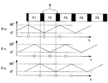
図6は、本実施形態に係るシャッターメガネ方式の立体映像表示装置の表示フレームと時分割シャッターの各位置での透過率についてのタイミングチャートである。
例えば、画像表示部1において、240fps(周期4.15ms)のフレームレートで動画が表示される。表示フレームDは、第1フレームF1、第2フレームF2、・・の各フレームとブランキング期間Bのタイミングを示す。
また、左眼用シャッターの走査の開始の位置L0、中間点の位置L1、終点の位置L2、右眼用シャッターの走査の開始の位置R0、中間点の位置R1、終点の位置R2についての光透過率TL0、TL1、TL2、TR0、TR1、TR2について示す。
例えば、左眼用シャッターの走査の開始の位置L0では、左眼用画像の走査の開始位置で光を透過する必要があるので、第1フレームF1,第3フレームF3などの奇数フレームの始まりの位置で透過率100%となり、その前ではなめらかに透過率が0%から増加し、後では0%へと減少する透過率プロファイルとなる。
左眼用シャッターの走査の中間点の位置L1では、第1フレームF1,第3フレームF3などの奇数フレームの中間点の位置で、終点の位置L2では奇数フレームの終わりの位置で、それぞれ透過率100%となり、その前後でなめらかに変化するプロファイルである。右眼用シャッターについても同様であって、右眼用シャッターの走査の開始の位置R0では、第2フレームF2,第4フレームF4などの偶数フレームの始まりの位置で透過率100%となり、その前ではなめらかに透過率が0%から増加し、後では0%へと減少する透過率プロファイルとなる。また、右眼用シャッターの走査の中間点の位置R1では、第2フレームF2,第4フレームF4などの偶数フレームの中間点の位置で、終点の位置R2では偶数フレームの終わりの位置で、それぞれ透過率100%となり、その前後でなめらかに変化するプロファイルである。
FIG. 6 is a timing chart regarding the transmissivity at each position of the display frame and the time-division shutter of the shutter glasses type stereoscopic image display device according to the present embodiment.
For example, in the
Also, the light for the start position L0, the middle point position L1, the end point position L2, the right eye shutter scan start position R0, the middle point position R1, and the end point position R2 of the left eye shutter. The transmittances T L0 , T L1 , T L2 , T R0 , T R1 , and T R2 are shown.
For example, since it is necessary to transmit light at the start position of the left eye image scan at the start position L0 of the left eye shutter, the start of odd frames such as the first frame F1 and the third frame F3 is started. The transmittance becomes 100% at the position, and before that, the transmittance increases smoothly from 0%, and after that, the transmittance profile decreases to 0%.
At the intermediate point position L1 of the left-eye shutter scanning, the transmittance is at the intermediate point position of the odd frame such as the first frame F1 and the third frame F3, and at the end point position L2 at the end position of the odd frame. The profile is 100% and changes smoothly before and after that. The same applies to the right-eye shutter. At the start position R0 of the right-eye shutter, the transmittance is 100% at the start position of even frames such as the second frame F2 and the fourth frame F4. Then, the transmittance profile increases smoothly from 0% and later decreases to 0%. Further, at the intermediate point position R1 of the right-eye shutter scanning, the intermediate point position of the even frame such as the second frame F2 and the fourth frame F4, and at the end point position R2, the end position of the even frame, respectively. The transmittance is 100%, and the profile changes smoothly before and after that.
図7は、図6に示す時分割シャッターの各位置での透過率のタイミングチャートに対して、画像を形成する1次元変調光の走査位置PSを重ねて示した図である。
各フレームの開始のタイミングでは、一次元変調光の走査位置は図5に示す走査の開始の位置S0となり、これは時分割シャッター上の左眼用シャッターの走査の開始の位置L0と右眼用シャッターの走査の開始の位置R0に対応する。
ここで、第1フレームF1及び第3フレームF3などの奇数フレームでは左眼用画像が再生され、左眼用シャッターの走査の開始の位置L0での透過率が100%となり、一方で右眼用シャッターの走査の開始の位置R0での透過率は0%となって、1次元変調光は左眼のみに入射する。
反対に、第2フレームF2及び第4フレームF4などの偶数フレームでは右眼用画像が再生されており、左眼用シャッターの走査の開始の位置L0での透過率が0%となり、一方で右眼用シャッターの走査の開始の位置R0での透過率は100%となって、1次元変調光は右眼のみに入射する。
各フレームの中間点や終わりなどの他のタイミングにおいても上記と同様であり、第1フレームF1及び第3フレームF3などの奇数フレームでは左眼用画像が再生され、対応する位置の左眼用シャッターの透過率が100%となり、対応する位置の右眼用シャッターの透過率が0%となって、1次元変調光は左眼のみに入射する。また、第2フレームF2及び第4フレームF4などの偶数フレームでは右眼用画像が再生され、対応する位置の左眼用シャッターの透過率が0%となり、対応する位置の右眼用シャッターの透過率が100%となって、1次元変調光は右眼のみに入射する。
Figure 7 is a diagram with respect to the timing chart of transmittance, it showed overlapping the scanning position P S of the one-dimensional modulated light to form an image at each position of the dividing shutter time shown in FIG.
At the start timing of each frame, the scan position of the one-dimensional modulated light is the scan start position S0 shown in FIG. 5, which is the start position L0 of the left-eye shutter on the time-division shutter and the right-eye scan position. This corresponds to the start position R0 of the shutter scanning.
Here, in the odd-numbered frames such as the first frame F1 and the third frame F3, the left-eye image is reproduced, and the transmittance at the start position L0 of the left-eye shutter is 100%, while the right-eye image is used. The transmittance at the shutter scanning start position R0 is 0%, and the one-dimensional modulated light is incident only on the left eye.
On the other hand, the right-eye image is reproduced in the even frames such as the second frame F2 and the fourth frame F4, and the transmittance at the start position L0 of the left-eye shutter is 0%, while The transmittance at the start position R0 of the ophthalmic shutter is 100%, and the one-dimensional modulated light is incident only on the right eye.
The same applies to other timings such as the midpoint and end of each frame, and the left-eye image is reproduced in odd frames such as the first frame F1 and the third frame F3, and the left-eye shutter at the corresponding position. The transmittance of the right eye shutter at the corresponding position is 0%, and the one-dimensional modulated light is incident only on the left eye. In the even frames such as the second frame F2 and the fourth frame F4, the right-eye image is reproduced, the transmittance of the left-eye shutter at the corresponding position is 0%, and the right-eye shutter at the corresponding position is transmitted. The rate is 100%, and the one-dimensional modulated light is incident only on the right eye.
上記のように画像表示面に右眼用画像及び左眼用画像を交互に表示し、時分割シャッターの開口部の位置を同期して制御することで、左眼用画像のフレームでは左眼用シャッターが開いて観察者の左眼で観察され、右眼用画像のフレームでは右眼用シャッターが開いて右眼で観察され、立体映像を観察することができる。 As described above, the image for the right eye and the image for the left eye are alternately displayed on the image display surface, and the position of the opening of the time-division shutter is controlled in synchronization so that the frame for the left eye is used for the left eye. The shutter is opened and observed with the left eye of the observer. In the frame of the right eye image, the right eye shutter is opened and observed with the right eye, and a stereoscopic image can be observed.
ここで、第1フレームF1の終点のタイミングについて注目すると、右眼用シャッターで次の第2フレームF2で走査の開始の位置R0で100%の透過率となるために、第1フレームF1の終点のタイミングで既に透過率が0%から上昇している。
しかし、1次元変調光の走査の位置は、フレームの終点である右端であり、一方で、上記の右眼用シャッターの走査の開始の位置は左端であり、この開口位置からは第1フレームの終点での光は観察できない。従って、フレームレートを高めてもクロストークを生じさせない。
Here, paying attention to the end point timing of the first frame F1, since the right eye shutter has a transmittance of 100% at the scanning start position R0 in the next second frame F2, the end point of the first frame F1. The transmittance has already increased from 0% at this timing.
However, the scanning position of the one-dimensional modulated light is the right end, which is the end point of the frame, while the scanning start position of the right-eye shutter is the left end. The light at the end point cannot be observed. Therefore, crosstalk does not occur even if the frame rate is increased.
同様の理由で、第2フレームの開始のタイミングでは、左眼用シャッターの右端で透過率が0%まで下がっていなが、このときの1次元変調光の走査の位置は、フレームの開始である左端であり、クロストークは発生しない。 For the same reason, at the start timing of the second frame, the transmittance does not decrease to 0% at the right end of the left-eye shutter, but the scanning position of the one-dimensional modulated light at this time is the start of the frame. At the left end, no crosstalk occurs.
本実施形態の立体映像表示装置によれば、右眼用画像の再生時に右眼用シャッターのうちの1次元変調光の走査位置に対応する部分のみが開くように制御され、フレームレートを高めてもクロストークを抑制することができる。
また、本実施形態においては、画像投影系などを2台用いず、1台のみで立体映像を表示することができる。
According to the stereoscopic image display apparatus of the present embodiment, when the right-eye image is reproduced, only the part corresponding to the scanning position of the one-dimensional modulated light in the right-eye shutter is controlled to increase the frame rate. Can also suppress crosstalk.
Further, in the present embodiment, it is possible to display a stereoscopic video with only one image projection system without using two image projection systems.
本実施形態に係る立体映像表示方法は、本実施形態に係る立体映像表示装置を用いて、以下のように行うことができる。
例えば、立体映像を視認するための視差に対応した右眼用画像及び左眼用画像を変調光の走査により交互に画像表示部の画像表示面に表示し、また、画像表示面と観察者の間に配置され、複数の領域に分割されて領域ごとに個別に開閉可能に構成された右眼用シャッターと左眼用シャッターを有する時分割シャッターにおいて、画像表示部における表示と時分割シャッターにおける開閉を同期させるように制御して、右眼用画像または左眼用画像の再生時にそれぞれ対応する右眼用シャッターまたは左眼用シャッターのうちの変調光の走査位置に対応する部分のみが開くように駆動する。
The stereoscopic video display method according to the present embodiment can be performed as follows using the stereoscopic video display device according to the present embodiment.
For example, a right-eye image and a left-eye image corresponding to parallax for viewing a stereoscopic image are alternately displayed on the image display surface of the image display unit by scanning with modulated light, and the image display surface and the viewer's In a time-division shutter having a right-eye shutter and a left-eye shutter that are arranged in between and divided into a plurality of areas and can be opened and closed individually for each area, display in the image display unit and opening and closing in the time-division shutter So that only the portion corresponding to the scanning position of the modulated light of the right-eye shutter or the left-eye shutter corresponding to the right-eye image or the left-eye shutter is opened. To drive.
例えば、時分割シャッターとして、右眼用シャッターと左眼用シャッターがそれぞれ液晶によって光透過率が変化する液晶シャッターであり、複数の領域に分割された電極を有する時分割シャッターを用いることができる。
また、例えば、画像表示部として、グレーティングライトバルブ素子を用いた画像表示部を用いることができる。
For example, as a time-division shutter, a right-eye shutter and a left-eye shutter are liquid crystal shutters whose light transmittance changes with liquid crystal, and a time-division shutter having electrodes divided into a plurality of regions can be used.
Further, for example, an image display unit using a grating light valve element can be used as the image display unit.
本実施形態の立体映像表示方法によれば、右眼用画像の再生時に右眼用シャッターのうちの1次元変調光の走査位置に対応する部分のみが開くことで、フレームレートを高めてもクロストークを抑制することができる。 According to the stereoscopic image display method of the present embodiment, only the portion corresponding to the scanning position of the one-dimensional modulated light in the right-eye shutter is opened at the time of reproducing the right-eye image, so that even if the frame rate is increased, cross Talk can be suppressed.
さらなる高いフレームレートでの映像表示が可能にするために、スクリーン上の領域を複数に分割し、それぞれの領域に対して画像光投影系を設けることで、スクリーン上の各領域において1次元変調光を走査することで、スクリーン全体で1つの画像を形成することも可能である。
図8はスクリーンを2つの領域に分割した場合の1次元変調光の走査による画像の表示について説明する模式図である。
例えば、x軸方向に並ぶ2つの領域に分割し、それぞれの領域に対応して、光源から走査ミラーまでの画像光投影系を2つ設ける。
In order to enable video display at a higher frame rate, the area on the screen is divided into a plurality of areas, and an image light projection system is provided for each area. It is also possible to form one image on the entire screen by scanning.
FIG. 8 is a schematic diagram for explaining display of an image by scanning one-dimensional modulated light when the screen is divided into two regions.
For example, it is divided into two regions arranged in the x-axis direction, and two image light projection systems from the light source to the scanning mirror are provided corresponding to each region.
スクリーン16上の2つの領域(16a,16b)において、それぞれ1次元変調光(17a,17b)が投影され、それぞれが走査方向DR(x軸方向)に走査され、領域16aにはこの領域に対応する画像が表示され、また、領域16bにはこの領域に対応する画像が表示され、領域16aと領域16bを合わせることにより、全体で1つの画像を表示できる。
その他、特許文献3に記載のような高いフレームレートを実現する構成及び方法を本実施形態に採用することが可能である。
In the two areas (16a, 16b) on the
In addition, a configuration and method for realizing a high frame rate as described in
本実施形態においては、上記のように複数個の走査光に対応して、時分割シャッターの位置を選択して開口するように制御することで、上記と同様の効果を享受することができる。 In the present embodiment, the same effect as described above can be obtained by controlling the position of the time-division shutter so as to open corresponding to a plurality of scanning lights as described above.
第2実施形態
図9は、本実施形態に係る偏光メガネ方式の立体映像表示装置の全体構成を示す模式図である。
例えば、画像表示部1と、偏光板4と、制御部3を有する。
画像表示部1は、例えば、立体映像を視認するための視差に対応した右眼用画像及び左眼用画像を、それぞれ互いに直交する偏光を有する変調光の走査により、交互に画像表示部の画像表示面に表示する。例えば、偏光角変調する画像光投影系15pとスクリーン16を有し、画像光投影系15pから投影された変調光がスクリーン16上で走査されて画像が表示される。変調光は、例えば後述するようにグレーティングライトバルブ素子を用いて得られる1次元変調光である。
偏光板4は、例えばメガネの形態である偏光メガネであり、画像表示部1の画像表示面と観察者Aの間に配置され、偏光角度が互いに直交しており、右眼用画像の偏光を透過させる右眼用偏光板4Rと左眼用画像の偏光を透過させる左眼用偏光板4Lを有する。
Second Embodiment FIG. 9 is a schematic diagram showing the overall configuration of a polarized glasses type stereoscopic image display apparatus according to this embodiment.
For example, the
For example, the
The
制御部3は、例えば、画像表示部1に無線方式または有線方式で接続して設けられ、偏光角変調板において、変調光の走査位置に対応する部分が右眼用画像の再生時に変調光を第1の偏光角に変調し、左眼用画像の再生時に変調光を第1の偏光角と直交する第2の偏光角に変調するように、画像表示部と偏光角変調板を同期させる。
For example, the
図10は、本実施形態に係る偏光メガネ方式の画像表示部の構成を示す模式図である。
第1実施形態と同様に、光源、照明レンズ、GLV素子、投射レンズ、走査ミラーなどから画像光投影系15が構成され、さらにレンズを介して偏光角変調板18が組み込まれて偏光角変調する画像光投影系15pが構成され、第1実施形態と同様にして、画像光投影系15pから投射された偏光した1次元変調光などの変調光が、レンズを介してスクリーン16上で走査されて画像が表示される。スクリーン16は、投射される光の偏光を保持する特性を有する。
FIG. 10 is a schematic diagram illustrating a configuration of a polarized glasses type image display unit according to the present embodiment.
As in the first embodiment, the image
本実施形態のGLV素子を用いた画像表示部では、例えば240fps、あるいは480fps以上の高いフレームレートでの映像表示が可能である。
また、第1実施形態と同様に、例えば青(B)、緑(G)、赤(R)の3色の光源を用いて、各色の光の1次元変調光を形成し、それを1つのレンズに投射して結合し、それを走査ミラーでスクリーン上に走査することで、カラー画像を表示することも可能である。
In the image display unit using the GLV element of the present embodiment, it is possible to display a video at a high frame rate of, for example, 240 fps or 480 fps or higher.
Similarly to the first embodiment, for example, by using three color light sources of blue (B), green (G), and red (R), one-dimensional modulated light of each color light is formed, It is also possible to display a color image by projecting and coupling to a lens and scanning it on a screen with a scanning mirror.
上記において、偏光角変調する画像光投影系15pを構成する偏光角変調板18は、例えば液晶素子により構成され、複数の領域に分割されて領域ごとに個別に、透過する光の偏光を変調可能に構成されている。上記の1次元変調光を用いている場合には、1次元変調光のパターンに沿ってスリット状の複数の領域に分割されて、領域ごとに個別に、透過する光の偏光を変調することが可能となっている。
In the above, the polarization
図11(a)は液晶素子による偏光角変調板の構成を示す模式図であり、図11(b)は断面図である。
偏光角変調板18は、例えば、1次元変調光などの変調光のパターンに沿った形状の領域で偏光角を変調可能なように、複数個に分割された電極183を有しており、この分割された電極183と、全面に形成された共通電極181との間の空間に液晶182が封入されて構成されている。
これにより、複数の領域に分割されて領域ごとに個別に透過する光の偏光を変調可能に構成されている。
FIG. 11A is a schematic diagram showing a configuration of a polarization angle modulation plate using a liquid crystal element, and FIG. 11B is a cross-sectional view.
The polarization
Thereby, it is comprised so that the polarization | polarized-light of the light divided | segmented into a several area | region and permeate | transmitted separately for every area | region can be modulated.
制御部3に含まれる、同期信号受信回路32と電圧走査回路33の動作により、分割電極183で選択された部分の偏光角を変調させることができ、画像表示部と偏光角変調板を制御して同期させて、変調光の走査位置に対応する部分が右眼用画像の再生時に変調光を第1の偏光角に変調し、左眼用画像の再生時に変調光を第1の偏光角と直交する第2の偏光角に変調する。
The operation of the synchronization
図12は偏光角変調板の模式平面図である。
偏光角変調板18において、1次元変調光は、投射レンズ13を経て走査ミラー14の走査により、偏光角変調板18上で図面上左側から右側へ走査方向DRXに走査される。
ここで、1つのフレームにおいて偏光角変調板18上の走査の開始の位置X0、中間点の位置X1、終点の位置X2とする。
FIG. 12 is a schematic plan view of a polarization angle modulation plate.
In the polarization
Here, in one frame, a scanning start position X0, an intermediate point position X1, and an end point position X2 on the polarization
図13は、本実施形態に係る偏光メガネ方式の立体映像表示装置の走査位置についてのタイミングチャートである。
ここでは、例えば奇数フレーム(第1フレームF1及び第3フレームF3・・)が左眼用画像、偶数フレーム(第2フレームF2及び第4フレームF4・・)が右眼用画像であるとする。
各フレームにおいて、1次元変調光の走査位置PSは、開始の位置S0から、中間点の位置S1、終点の位置S2へと移動する。
このとき、左眼用画像を表示する奇数フレームでは、偏光角変調板18により偏光角が90度となるように制御され、一方、右眼用画像を表示する偶数フレームでは、偏光角変調板18により偏光角が0度となるように、1次元変調光の走査位置に対応する部分が電圧に応じて偏光角を変調しながら駆動する。即ち、1次元変調光の走査位置PSに同期して、偏光角変調板の変調部の位置PXが、走査の開始の位置X0から、中間点の位置X1、終点の位置X2へと移動する。
FIG. 13 is a timing chart for the scanning position of the polarizing glasses type stereoscopic image display apparatus according to the present embodiment.
Here, for example, it is assumed that odd frames (first frame F1 and third frame F3...) Are left eye images, and even frames (second frame F2 and fourth frames F4...) Are right eye images.
In each frame, one-dimensional scanning position P S of the modulated light is moved from the position S0 of the start position S1 of the intermediate point, to the position S2 of the end point.
At this time, in the odd-numbered frame displaying the left-eye image, the polarization
図14は、本実施形態に係る偏光メガネ方式の立体映像表示装置の表示フレームと偏光角変調板のX0、X1、X2の各位置での偏光角についてのタイミングチャートである。
例えば、画像表示部1において、240fps(周期4.15ms)のフレームレートで動画が表示される。表示フレームDは、第1フレームF1、第2フレームF2、・・の各フレームとブランキング期間Bのタイミングを示す。
また、偏光角変調板の走査の開始の位置X0、中間点の位置X1、終点の位置X2についての偏光角θX0、θX1、θX2について示す。
例えば、偏光角変調板の走査の開始の位置X0では、左眼用画像の走査の開始位置で偏光を90度にする必要があるので、奇数フレームの始まりの位置で偏光角90度となり、さらに右眼用画像の走査の開始位置で偏光を0度にする必要があるので、偶数フレームの始まりの位置で偏光角0度となり、上記以外の位置では上記の90度と0度をなめらかにつなぐように変化する偏光角プロファイルとなる。
偏光角変調板の走査の中間点の位置X1、終点の位置X2についても同様である。
FIG. 14 is a timing chart of the polarization angle at the X0, X1, and X2 positions of the display frame of the polarized glasses type stereoscopic image display device according to the present embodiment and the polarization angle modulation plate.
For example, in the
Further, the polarization angles θ X0 , θ X1 , and θ X2 for the scanning start position X0, the intermediate point position X1, and the end point position X2 of the polarization angle modulation plate are shown.
For example, at the scanning start position X0 of the polarization angle modulation plate, it is necessary to set the polarization to 90 degrees at the scanning start position of the image for the left eye, so that the polarization angle becomes 90 degrees at the starting position of the odd frame. Since it is necessary to set the polarization to 0 degree at the start position of scanning of the image for the right eye, the polarization angle becomes 0 degree at the start position of the even frame, and the above 90 degrees and 0 degrees are smoothly connected at other positions. Thus, the polarization angle profile changes.
The same applies to the position X1 of the intermediate point of scanning of the polarization angle modulation plate and the position X2 of the end point.
上記のように画像表示面に右眼用画像及び左眼用画像を交互に表示すると、左眼用画像が90度の偏光角、右眼用画像は0度の偏光角を有するので、偏向板を用いて観察することで、左眼用画像のフレームでは右眼用偏光板を透過せず、左眼用偏光板を透過して観察者の左眼で観察され、一方、右眼用画像のフレームでは左眼用偏光板を透過せず、右眼用偏光板を透過して右眼で観察され、立体映像を観察することができる。 When the right-eye image and the left-eye image are alternately displayed on the image display surface as described above, the left-eye image has a polarization angle of 90 degrees and the right-eye image has a polarization angle of 0 degrees. In the left-eye image frame, the right-eye polarizing plate does not pass through the left-eye polarizing plate, and the left-eye polarizing plate passes through the left-eye polarizing plate. The frame does not pass through the polarizing plate for the left eye, passes through the polarizing plate for the right eye, and is observed with the right eye, so that a stereoscopic image can be observed.
ここで、第1フレームF1などの奇数フレームにおいては、走査のどのタイミングにおいても90度の偏光角を有する1次元変調光が投射され、第2フレームなどの偶数フレームでは0度の変調角を有する1次元変調光が投射される。
上記のように、左眼用画像である奇数フレームと右眼用画像である偶数フレームの画像光はそれぞれ互いに直交する偏光となっており、これらに適合するように互いに直交する偏光角を有する左眼用偏光板と右眼用偏光板を用いるので、左眼用画像が右眼用偏光板を、右眼用画像が左眼用偏光板通過することがなく、フレームレートを高めてもクロストークを生じさせない。
Here, in odd frames such as the first frame F1, one-dimensional modulated light having a polarization angle of 90 degrees is projected at any scanning timing, and in even frames such as the second frame, it has a modulation angle of 0 degrees. One-dimensional modulated light is projected.
As described above, the image light of the even frame is an odd frame and the right-eye image is the left-eye image has a respective polarization orthogonal to each other, the left having a polarization angle orthogonal to each other to conform to these Since the polarizing plate for the eye and the polarizing plate for the right eye are used, the image for the left eye does not pass through the polarizing plate for the right eye, and the image for the right eye does not pass through the polarizing plate for the left eye. Does not cause.
本実施形態の立体映像表示装置によれば、右眼用画像及び左眼用画像を、それぞれ互いに直交する偏光を有する変調光の走査で表示することにより、フレームレートを高めてもクロストークを抑制することができる。
また、本実施形態においては、画像投影系などを2台用いず、1台のみで立体映像を表示することができる。
According to the stereoscopic image display apparatus of the present embodiment, right-eye images and left-eye images are displayed by scanning modulated light beams having polarized light that are orthogonal to each other, thereby suppressing crosstalk even when the frame rate is increased. can do.
Further, in the present embodiment, it is possible to display a stereoscopic video with only one image projection system without using two image projection systems.
本実施形態に係る立体映像表示方法は、本実施形態に係る立体映像表示装置を用いて、以下のように行うことができる。
例えば、立体映像を視認するための視差に対応した右眼用画像及び左眼用画像を、それぞれ互いに直交する偏光を有する変調光の走査により、交互に画像表示部の画像表示面に表示し、画像表示面と観察者の間に、偏光角度が互いに直交しており、右眼用画像の偏光を透過させる右眼用偏光板と左眼用画像の偏光を透過させる左眼用偏光板を有する偏光板を配置して、右眼用画像を観察者の右眼で、左眼用画像を観察者の左眼で観察させる。
The stereoscopic video display method according to the present embodiment can be performed as follows using the stereoscopic video display device according to the present embodiment.
For example, a right-eye image and a left-eye image corresponding to parallax for visually recognizing a stereoscopic image are alternately displayed on the image display surface of the image display unit by scanning with modulated light having mutually orthogonal polarizations, Between the image display surface and the observer, polarization angles are orthogonal to each other, and a right-eye polarizing plate that transmits the polarized light of the right-eye image and a left-eye polarizing plate that transmits the polarized light of the left-eye image are provided. A polarizing plate is arranged to allow the right eye image to be observed by the observer's right eye and the left eye image to be observed by the observer's left eye.
例えば、画像表示部において、複数の領域に分割された電極を有する液晶素子であって、透過する光の偏光を液晶によって領域ごとに個別に変調可能に構成された偏光角変調板を用いて、偏光角が変調される
また、例えば、偏光角変調板において、画像表示部と偏光角変調板を同期させるように制御して、変調光の走査位置に対応する部分が右眼用画像の再生時に変調光を第1の偏光角に変調し、左眼用画像の再生時に変調光を前記第1の偏光角と直交する第2の偏光角に変調するように、偏光角変調板を駆動する。
また、例えば、画像表示部として、グレーティングライトバルブ素子を用いた画像表示部を用いる。
For example, in the image display unit, a liquid crystal element having an electrode divided into a plurality of regions, and using a polarization angle modulation plate configured to individually modulate the polarization of transmitted light by the liquid crystal for each region, Also, for example, in the polarization angle modulation plate, the image display unit and the polarization angle modulation plate are controlled to be synchronized so that the portion corresponding to the scanning position of the modulated light is at the time of reproducing the right-eye image. The modulation light is modulated to the first polarization angle, and the polarization angle modulation plate is driven so as to modulate the modulation light to the second polarization angle orthogonal to the first polarization angle when reproducing the left-eye image.
Further, for example, an image display unit using a grating light valve element is used as the image display unit.
本実施形態の立体映像表示方法によれば、右眼用画像及び左眼用画像を、それぞれ互いに直交する偏光を有する変調光の走査で表示することにより、フレームレートを高めてもクロストークを抑制することができる。 According to the stereoscopic image display method of the present embodiment, the right-eye image and the left-eye image are displayed by scanning modulated light beams having polarized light that are orthogonal to each other, thereby suppressing crosstalk even when the frame rate is increased. can do.
さらなる高いフレームレートでの映像表示が可能にするために、スクリーン上の領域を複数に分割し、それぞれの領域に対して画像光投影系を設けることで、スクリーン上の各領域において1次元変調光を走査することで、スクリーン全体で1つの画像を形成することも可能である。
第1実施形態と同様に、図8に示すように、スクリーンを2つの領域に分割した場合の1次元変調光の走査による画像の表示について場合には、例えば、x軸方向に並ぶ2つの領域に分割し、それぞれの領域に対応して、光源から走査ミラーまでの画像光投影系を2つ設ける。
In order to enable video display at a higher frame rate, the area on the screen is divided into a plurality of areas, and an image light projection system is provided for each area. It is also possible to form one image on the entire screen by scanning.
As in the first embodiment, as shown in FIG. 8, in the case of displaying an image by scanning one-dimensional modulated light when the screen is divided into two regions, for example, two regions arranged in the x-axis direction. Two image light projection systems from the light source to the scanning mirror are provided corresponding to each region.
スクリーン16上の2つの領域(16a,16b)において、それぞれ1次元変調光(17a,17b)が投影され、それぞれが走査方向DR(x軸方向)に走査され、領域16aにはこの領域に対応する画像が表示され、また、領域16bにはこの領域に対応する画像が表示され、領域16aと領域16bを合わせることにより、全体で1つの画像を表示できる。
その他、特許文献3に記載のような高いフレームレートを実現する構成及び方法を本実施形態に採用することが可能である。
In the two areas (16a, 16b) on the
In addition, a configuration and method for realizing a high frame rate as described in
本実施形態においては、上記のように複数個の走査光に対応して、偏光角変調板の駆動部分の位置を選択するように制御することで、上記と同様の効果を享受することができる。 In the present embodiment, the same effect as described above can be obtained by controlling the position of the drive portion of the polarization angle modulation plate corresponding to a plurality of scanning lights as described above. .
本発明は上記の説明に限定されない。
例えば、走査の方向は特に限定されず、左右方向または上下方向どちらでもよい。
第1実施形態において、画像表示部は変調光の走査によって右眼用画像及び左眼用画像を表示すること可能であればよく、上記のような1次元の変調光を走査して画像を形成するGLV素子を用いた画像表示部はもちろん、液晶表示部、FED(Field Emission Display)などの線順次方式の表示部や、CRT(陰極線管)のような点走査方式の表示装置を用いることができる。上記の点走査方式の場合、表示装置部において一の方向に走査して得られる1次元の表示光を上記の1次元変調光と同様に扱うことにより、本発明の立体映像表示装置として適用することができる。また、時分割シャッターの領域の分割パターンをマトリクス状などの細かい領域に分割するようにしてもよい。
また、第2実施形態の画像表示装置としては、表示画面からの表示光が偏光を有していることが必要であり、実施形態に示したプロジェクター型の表示装置の他、液晶表示装置などを用いることができる。
また、第2実施形態の画像表示装置としては、表示画面からの表示光が第1の偏光角と第1の偏光角に直交する第2の偏光角とを有していることが必要であり、表示光は直線偏光でなく円偏光であってもよい。
また、時分割シャッターをメガネの様態とせずに、壁や装置筐体に設けた右眼用および左眼用の穴に設けた時分割シャッターとすることもできる。
その他、本発明の要旨を逸脱しない範囲で、種々の変更が可能である。
The present invention is not limited to the above description.
For example, the scanning direction is not particularly limited, and may be either the horizontal direction or the vertical direction.
In the first embodiment, the image display unit only needs to be able to display an image for the right eye and an image for the left eye by scanning the modulated light, and scans the one-dimensional modulated light as described above to form an image. In addition to an image display unit using a GLV element, a liquid crystal display unit, a line sequential display unit such as an FED (Field Emission Display), or a point scanning display device such as a CRT (cathode ray tube) may be used. it can. In the case of the above-described point scanning method, the one-dimensional display light obtained by scanning in one direction in the display device unit is handled in the same manner as the above-described one-dimensional modulated light, thereby being applied as the stereoscopic image display device of the present invention. be able to. Further, the division pattern of the time division shutter area may be divided into fine areas such as a matrix.
In addition, as the image display device of the second embodiment, it is necessary that the display light from the display screen has polarization. In addition to the projector-type display device shown in the embodiment, a liquid crystal display device or the like can be used. Can be used.
In the image display device according to the second embodiment, it is necessary that the display light from the display screen has the first polarization angle and the second polarization angle orthogonal to the first polarization angle. The display light may be circularly polarized light instead of linearly polarized light.
Further, the time-division shutter may be a time-division shutter provided in a hole for a right eye and a left eye provided in a wall or an apparatus housing without using a state of glasses.
In addition, various modifications can be made without departing from the scope of the present invention.
本発明の立体映像表示装置及び立体映像表示方法は、映像を立体に表示することができる表示装置及び方法に適用できる。 The 3D image display apparatus and 3D image display method of the present invention can be applied to a display apparatus and method capable of displaying an image in 3D.
1…画像表示部、2…時分割シャッター、2R…右眼用シャッター、2L…左眼用シャッター、3…制御部、3a…第1制御部、3b…第2制御部、4…偏光板、4L…左眼用偏光板、4R…右眼用偏光板、10…光源、11…照明レンズ、12…GLV素子、13…投射レンズ、14…走査ミラー、15…画像光投影系、15p…偏光角変調する画像光投影系、16,16a,16b…スクリーン、17,17a,17b…1次元変調光、18…偏光角変調板、20…第1偏光板、21…共通電極、22…液晶、23…分割電極、24…第2偏光板、30…同期信号受信回路、31…電圧走査回路、181…共通電極、182…液晶、183…分割された電極、D…表示フレーム、B…ブランキング期間、F1〜F8…フレーム、A…観察者、PS…走査位置
DESCRIPTION OF
Claims (8)
前記画像表示面と観察者の間に配置され、複数の領域に分割されて前記領域ごとに個別に開閉可能に構成された右眼用シャッターと左眼用シャッターを有する時分割シャッターと、
前記時分割シャッターにおいて、前記右眼用画像または前記左眼用画像の再生時にそれぞれ対応する前記右眼用シャッターまたは前記左眼用シャッターのうちの前記変調光の走査位置に対応する部分のみが開くように、前記画像表示部における前記変調光の走査位置と前記時分割シャッターにおける開閉を同期させる制御部と
を有する立体映像表示装置。 An image display unit that alternately displays a right-eye image and a left-eye image corresponding to parallax for visually recognizing a stereoscopic image on an image display surface by scanning with modulated light;
A time-division shutter having a right-eye shutter and a left-eye shutter, which is arranged between the image display surface and the observer, divided into a plurality of regions and configured to be individually openable and closable for each region;
In the time-division shutter, only a portion corresponding to the scanning position of the modulated light in the right-eye shutter or the left-eye shutter corresponding to the right-eye image or the left-eye image is opened. as such, that having a control unit for synchronizing the opening and closing of said time division shutter and the scanning position of the modulated light in the image display unit steric video display device.
請求項1に記載の立体映像表示装置。 The stereoscopic image display apparatus according to claim 1, wherein the right-eye shutter and the left-eye shutter are liquid crystal shutters whose light transmittance is changed by liquid crystal, respectively, and the electrodes are divided into the plurality of regions.
請求項1または2に記載の立体映像表示装置。 The stereoscopic image display device according to claim 1 or 2, the image display section is an image display unit using a grating light valve device.
前記画像表示面と観察者の間に配置され、複数の領域に分割されて前記領域ごとに個別に開閉可能に構成された右眼用シャッターと左眼用シャッターを有する時分割シャッターにおいて、前記画像表示部における前記変調光の走査位置と前記時分割シャッターにおける開閉を同期させるように制御して、前記右眼用画像または前記左眼用画像の再生時にそれぞれ対応する前記右眼用シャッターまたは前記左眼用シャッターのうちの前記変調光の走査位置に対応する部分のみが開くように駆動する工程と
を有する立体映像表示方法。 Displaying a right-eye image and a left-eye image corresponding to parallax for viewing a stereoscopic image alternately on the image display surface of the image display unit by scanning with modulated light; and
In the time-division shutter having a right-eye shutter and a left-eye shutter, which are arranged between the image display surface and an observer and divided into a plurality of regions and configured to be individually openable and closable for each region, the image The right-eye shutter or the left-eye corresponding to the reproduction of the right-eye image or the left-eye image is controlled by synchronizing the scanning position of the modulated light on the display unit with the opening and closing of the time-division shutter. steric image display method that have a a step of driving so that the only portions corresponding to the scanning position of the modulated light open of eye shutter.
請求項4に記載の立体映像表示方法。 The right-eye shutter and the left-eye shutter are liquid crystal shutters whose light transmittance is changed by liquid crystal as the time-division shutter, and time-division shutters having electrodes divided into the plurality of regions are used. 4. The stereoscopic image display method according to 4.
請求項4または5に記載の立体映像表示方法。 The stereoscopic image display method according to claim 4 , wherein an image display unit using a grating light valve element is used as the image display unit.
複数の領域に分割されて前記領域ごとに個別に開閉可能に構成された右眼用シャッターと左眼用シャッターを有する時分割シャッターとを有し、
前記変調光の各走査位置に応じて、前記時分割シャッターの開口位置を走査させる
立体映像表示装置。 An image display unit that alternately displays an image for the right eye and an image for the left eye on the image display surface by scanning with modulated light;
A right-eye shutter that is divided into a plurality of areas and configured to be individually openable and closable for each of the areas, and a time-division shutter having a left-eye shutter;
A stereoscopic image display device that scans the opening position of the time-division shutter according to each scanning position of the modulated light.
複数の領域に分割されて前記領域ごとに個別に開閉可能に構成された右眼用シャッターと左眼用シャッターを有する時分割シャッターとを有し、
画像表示部の各走査位置に応じて、前記時分割シャッターの開口位置を走査させる
立体映像表示装置。 An image display unit that alternately displays an image for the right eye and an image for the left eye on the image display surface by scanning in a line sequential manner;
A right-eye shutter that is divided into a plurality of areas and configured to be individually openable and closable for each of the areas, and a time-division shutter having a left-eye shutter;
A stereoscopic image display device that scans the opening position of the time-division shutter according to each scanning position of the image display unit.
Priority Applications (1)
| Application Number | Priority Date | Filing Date | Title |
|---|---|---|---|
| JP2007195012A JP5104096B2 (en) | 2007-07-26 | 2007-07-26 | 3D image display apparatus and 3D image display method |
Applications Claiming Priority (1)
| Application Number | Priority Date | Filing Date | Title |
|---|---|---|---|
| JP2007195012A JP5104096B2 (en) | 2007-07-26 | 2007-07-26 | 3D image display apparatus and 3D image display method |
Publications (3)
| Publication Number | Publication Date |
|---|---|
| JP2009031524A JP2009031524A (en) | 2009-02-12 |
| JP2009031524A5 JP2009031524A5 (en) | 2010-07-29 |
| JP5104096B2 true JP5104096B2 (en) | 2012-12-19 |
Family
ID=40402094
Family Applications (1)
| Application Number | Title | Priority Date | Filing Date |
|---|---|---|---|
| JP2007195012A Expired - Fee Related JP5104096B2 (en) | 2007-07-26 | 2007-07-26 | 3D image display apparatus and 3D image display method |
Country Status (1)
| Country | Link |
|---|---|
| JP (1) | JP5104096B2 (en) |
Families Citing this family (7)
| Publication number | Priority date | Publication date | Assignee | Title |
|---|---|---|---|---|
| JPWO2010119490A1 (en) * | 2009-04-14 | 2012-10-18 | パナソニック株式会社 | 3D image display device |
| US9436016B2 (en) | 2009-06-19 | 2016-09-06 | Nec Corporation | Liquid crystal shutter eyeglass |
| US8643707B2 (en) | 2009-09-07 | 2014-02-04 | Panasonic Corporation | Image signal processing apparatus, image signal processing method, recording medium, and integrated circuit |
| CN101776802B (en) * | 2010-01-12 | 2011-07-27 | 友达光电股份有限公司 | Stereoscopic display, display method of stereoscopic display and method for displaying stereoscopic image |
| KR20110129329A (en) * | 2010-05-25 | 2011-12-01 | 삼성전자주식회사 | Stereoscopic display apparatus and method of driving the same |
| WO2011152451A1 (en) * | 2010-06-01 | 2011-12-08 | シャープ株式会社 | Display device executing time-shared driving, shutter device, and display system |
| JP2012109763A (en) * | 2010-11-17 | 2012-06-07 | Seiko Epson Corp | Shutter spectacles and image display system |
Family Cites Families (7)
| Publication number | Priority date | Publication date | Assignee | Title |
|---|---|---|---|---|
| JPS6346410A (en) * | 1986-08-13 | 1988-02-27 | Sharp Corp | Pseudo stereoscopic display system |
| JPH11194299A (en) * | 1997-12-27 | 1999-07-21 | Mr System Kenkyusho:Kk | Display device |
| JP2001045524A (en) * | 1999-01-26 | 2001-02-16 | Denso Corp | Stereoscopic display device |
| JP2000347132A (en) * | 1999-06-09 | 2000-12-15 | Mr System Kenkyusho:Kk | Picture display device and method |
| JP2001264691A (en) * | 2000-03-14 | 2001-09-26 | Mixed Reality Systems Laboratory Inc | Stereoscopic image display device and method |
| JP2005115177A (en) * | 2003-10-09 | 2005-04-28 | Sony Corp | Three-dimensional image display device and method of displaying three-dimensional image |
| JP4331134B2 (en) * | 2005-03-25 | 2009-09-16 | 株式会社東芝 | Stereoscopic image display device |
-
2007
- 2007-07-26 JP JP2007195012A patent/JP5104096B2/en not_active Expired - Fee Related
Also Published As
| Publication number | Publication date |
|---|---|
| JP2009031524A (en) | 2009-02-12 |
Similar Documents
| Publication | Publication Date | Title |
|---|---|---|
| JP4985184B2 (en) | 3D image display apparatus and 3D image display method | |
| US8233035B2 (en) | Dual-view stereoscopic display using linear modulator arrays | |
| US8937766B2 (en) | Stereoscopic display using multi-linear electromechanical modulator | |
| US7123213B2 (en) | Three dimensional display unit and display method | |
| EP2443837B1 (en) | Dynamic illumination control for laser projection display | |
| JP5104096B2 (en) | 3D image display apparatus and 3D image display method | |
| US20100202047A1 (en) | Stereo display system with scanning of light valves | |
| JP2007004179A (en) | 3d image display apparatus serving 2d | |
| JP4676874B2 (en) | Projection-type 3D image display device using one projector | |
| JP2009151151A (en) | Stereoscopic video display apparatus | |
| JP5532588B2 (en) | Image display device and image display method | |
| JP2010164852A (en) | Stereoscopic image display device and stereoscopic image display method | |
| JP2008209476A (en) | Stereoscopic image display device | |
| JP3605572B2 (en) | Three-dimensional image display device, point light emitting member and point light transmitting member | |
| JP2008058583A (en) | Three-dimensional image display device and three-dimensional image display method | |
| JP3753763B2 (en) | Apparatus and method for recognizing 3D image | |
| JP2006058588A (en) | Optical device, optical apparatus, display apparatus and stereoscopic image display apparatus | |
| JP2010278955A (en) | Image processing apparatus, electro-optical device, display method and electronic equipment | |
| JP2966782B2 (en) | 3D image display device | |
| JP2953433B2 (en) | 3D display device | |
| KR101022474B1 (en) | Stereoscopic image display apparatus | |
| JPH04250439A (en) | Screen for stereoscopic display, stereoscopic display device and its driving method | |
| JP3634486B2 (en) | 3D image display method | |
| JP3108351B2 (en) | Projection type stereoscopic image display device | |
| JPS61144690A (en) | 3-d dispaly unit |
Legal Events
| Date | Code | Title | Description |
|---|---|---|---|
| A521 | Written amendment |
Free format text: JAPANESE INTERMEDIATE CODE: A523 Effective date: 20100609 |
|
| A621 | Written request for application examination |
Free format text: JAPANESE INTERMEDIATE CODE: A621 Effective date: 20100609 |
|
| A977 | Report on retrieval |
Free format text: JAPANESE INTERMEDIATE CODE: A971007 Effective date: 20111208 |
|
| A131 | Notification of reasons for refusal |
Free format text: JAPANESE INTERMEDIATE CODE: A131 Effective date: 20111220 |
|
| A521 | Written amendment |
Free format text: JAPANESE INTERMEDIATE CODE: A523 Effective date: 20120209 |
|
| TRDD | Decision of grant or rejection written | ||
| A01 | Written decision to grant a patent or to grant a registration (utility model) |
Free format text: JAPANESE INTERMEDIATE CODE: A01 Effective date: 20120904 |
|
| A01 | Written decision to grant a patent or to grant a registration (utility model) |
Free format text: JAPANESE INTERMEDIATE CODE: A01 |
|
| A61 | First payment of annual fees (during grant procedure) |
Free format text: JAPANESE INTERMEDIATE CODE: A61 Effective date: 20120917 |
|
| FPAY | Renewal fee payment (event date is renewal date of database) |
Free format text: PAYMENT UNTIL: 20151012 Year of fee payment: 3 |
|
| LAPS | Cancellation because of no payment of annual fees |