JP5102886B2 - Image display system, image display method, and program - Google Patents
Image display system, image display method, and program Download PDFInfo
- Publication number
- JP5102886B2 JP5102886B2 JP2011055410A JP2011055410A JP5102886B2 JP 5102886 B2 JP5102886 B2 JP 5102886B2 JP 2011055410 A JP2011055410 A JP 2011055410A JP 2011055410 A JP2011055410 A JP 2011055410A JP 5102886 B2 JP5102886 B2 JP 5102886B2
- Authority
- JP
- Japan
- Prior art keywords
- image
- image display
- ship
- display device
- position information
- Prior art date
- Legal status (The legal status is an assumption and is not a legal conclusion. Google has not performed a legal analysis and makes no representation as to the accuracy of the status listed.)
- Active
Links
Images


Classifications
-
- B—PERFORMING OPERATIONS; TRANSPORTING
- B63—SHIPS OR OTHER WATERBORNE VESSELS; RELATED EQUIPMENT
- B63B—SHIPS OR OTHER WATERBORNE VESSELS; EQUIPMENT FOR SHIPPING
- B63B43/00—Improving safety of vessels, e.g. damage control, not otherwise provided for
- B63B43/18—Improving safety of vessels, e.g. damage control, not otherwise provided for preventing collision or grounding; reducing collision damage
-
- B—PERFORMING OPERATIONS; TRANSPORTING
- B63—SHIPS OR OTHER WATERBORNE VESSELS; RELATED EQUIPMENT
- B63B—SHIPS OR OTHER WATERBORNE VESSELS; EQUIPMENT FOR SHIPPING
- B63B49/00—Arrangements of nautical instruments or navigational aids
-
- B—PERFORMING OPERATIONS; TRANSPORTING
- B63—SHIPS OR OTHER WATERBORNE VESSELS; RELATED EQUIPMENT
- B63B—SHIPS OR OTHER WATERBORNE VESSELS; EQUIPMENT FOR SHIPPING
- B63B79/00—Monitoring properties or operating parameters of vessels in operation
- B63B79/10—Monitoring properties or operating parameters of vessels in operation using sensors, e.g. pressure sensors, strain gauges or accelerometers
Description
本発明は、画像表示システム及び画像表示方法及びプログラムに関する。 The present invention relates to an image display system, an image display method, and a program.
目的地までの道案内や作業時における作業手順の提示等、様々な分野でナビゲーション技術が利用されている。ナビゲーション技術とは、ある行為を遂行し易くするよう支援を行う技術であるため、出来るだけ直感的に理解できるような仕組みが以前から求められている。そのような仕組みの一つとして、文字や画像等コンピュータで管理されているデータを、現実の環境へ重畳表示させ、現実の環境に補足的な情報を与える拡張現実と呼ばれる技術を利用したナビゲーション技術が存在する。例えば、船舶の分野においても、様々なナビゲーション技術が開発されてきた。 Navigation technology is used in various fields such as route guidance to a destination and presentation of work procedures during work. Since navigation technology is a technology that assists in facilitating certain actions, a mechanism that can be understood as intuitively as possible has been demanded. As one of such mechanisms, navigation technology using a technology called augmented reality that superimposes data managed by computers such as text and images on the real environment and gives supplementary information to the real environment. Exists. For example, various navigation techniques have been developed in the field of ships.
船舶の運航には、古くは海図を使った航行、現在はレーダー装置やGPS等を利用した航行が行われている。ところで沿岸部を運航する船舶の場合、暗礁への座礁等、海面下の障害物に対するトラブルを避けるために上記機器を駆使することになる。また、沿岸部に限らず、濃霧等により他の船舶との接触を避けるためにも海上では目視だけでなく、機器からの情報を活用している。
これら機器を活用して座礁や他船との接触を避けることを高めることは可能であるが、より直感的に危険を察知・回避できる仕組みが望まれている。例えば非特許文献1には、船舶自動識別システム(AIS)と電子海図とを組み合わせて3次元表示する仕組みが開示されている。しかしながら、結局のところ船員は非特許文献1の図7のようなグラフ表示を理解して衝突等の判断をすることが求められる。
In the past, navigating using nautical charts has been used for ship operations, and currently navigating using radar devices and GPS. By the way, in the case of a ship that operates in the coastal area, the above equipment is used to avoid troubles due to obstacles under the sea surface, such as landing on a reef. Moreover, not only in coastal areas, but also in the ocean, information from equipment is used to avoid contact with other ships due to dense fog or the like.
Although it is possible to increase the avoidance of contact with grounding and other ships using these devices, a mechanism that can detect and avoid danger more intuitively is desired. For example, Non-Patent
しかしながら、船舶の運航のように、常に状況が変化しうる環境において、直感的に理解できるようにするには、情報の得られるタイミングや情報の種類等に関して限りなく現実に近く、即時に知覚できるような状態で提示することが求められていた。本発明は、船舶が航行する際に有益な情報を、船員等が直感的に状況を把握可能に提供することを目的とする。 However, in order to be able to understand intuitively in an environment where the situation is constantly changing, such as ship operations, the timing of obtaining information and the type of information are almost realistic and can be perceived immediately. It was requested to present in such a state. An object of this invention is to provide useful information when a ship navigates so that a crew member etc. can grasp | ascertain a situation intuitively.
そこで、本発明は、船舶の位置情報を取得する位置情報取得装置と、海底形状を含む電子海図と潮位表とを記憶する情報記憶装置と、画像表示装置と、前記画像表示装置に画像を提供する画像提供装置と、を含む画像表示システムであって、前記画像提供装置は、前記位置情報取得装置で取得された前記船舶の位置情報と、前記潮位表と、電子海図の示す水深に関する情報と、に基づいて、前記船舶の位置の海面下の深度を求め、前記位置情報と、前記海面下の深度と、前記電子海図の示す海底地形画像データと、に基づいて、前記船舶の位置の前記深度の海面下の海底形状の仮想空間画像を作成し、前記画像表示装置に提供し、前記画像表示装置は、前記画像提供装置より提供された海底形状の仮想空間画像を前記画像表示装置からの風景に重畳して表示する。 Therefore, the present invention provides a position information acquisition device that acquires ship position information, an information storage device that stores an electronic chart including a seabed shape and a tide table, an image display device, and an image provided to the image display device An image display system comprising: an image display system including the position information of the ship acquired by the position information acquisition apparatus, the tide table, and information relating to a water depth indicated by an electronic chart. The depth of the ship below the sea level is obtained based on the position information, the depth below the sea surface, and the seafloor topographic image data indicated by the electronic chart, A virtual space image of a seabed shape under the sea surface at a depth is created and provided to the image display device, and the image display device outputs a seafloor shape virtual space image provided by the image providing device from the image display device. Landscape Superimposed and displayed.
本発明によれば、船舶が航行する際に有益な情報を、船員等が直感的に状況を把握可能に提供することができる。 ADVANTAGE OF THE INVENTION According to this invention, when a ship sails, a crew member etc. can provide a situation in which a crew member etc. can grasp | ascertain intuitively.
以下、本発明の実施形態について図面に基づいて説明する。 Hereinafter, embodiments of the present invention will be described with reference to the drawings.
<実施形態1>
以下、実施形態1を説明する。
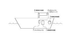
図1は、実施形態1の画像表示システムのシステム構成の一例を示す図である。図1に示されるように、実施形態1の画像表示システムは、船舶の位置情報を取得するGPSコンパス(又はGPSレシーバ)2と、海底形状を含む電子海図と潮位表とを記憶する情報記憶装置5と、画像表示装置4と、画像表示装置4に画像を提供する画像提供装置1と、船舶の方位を取得するジャイロコンパス7と、船舶の航行を制御する航行制御装置6と、がネットワークを介して接続されている。
位置情報取得装置の一例であるGPSコンパス(又はGPSレシーバ)2は、船舶の位置情報(経度、緯度)を取得する。なお、位置情報取得装置の一例としては、GPSコンパスであってもよいし、GPSレシーバであってもよいが、以下では説明の簡略化のため、GPSコンパスを例に説明を行う。
向き取得装置の一例であるジャイロコンパス7は、船舶の向きを取得する。
画像提供装置1は、GPSコンパス2で取得された船舶の位置情報と、情報記憶装置5に記憶されている潮位表と電子海図と、に基づいて、前記船舶の位置の海面下の深度を求める。なお、潮位表とは、ある位置情報における時刻と基本水準面等を基準に計測した海面の高低とを対応付けて表したデータであり、海上保安庁等より発行されている。また、電子海図とは、例えば、海上保安庁等より発行されている電子化された海の地図データのことであり、航海用海図や特殊図、海の基本図、沿岸海域地形図、沿岸海域土地条件図、海洋地質図等、目的によって種々に分類されている。電子海図には、例えば、基本水準面等を基準に計測した水深に関する情報や、水路の状況、海流や潮流、標識、海岸の状態等が記載されており、例えば、海の基本図には、海底の地形を等深線で表した海底地形図や前記海底地形の3次元俯瞰地図等が含まれている。画像提供装置1は、前記位置情報と、前記潮位表と、電子海図の示す水深に関する情報とに基づいて、前記深度を計算で求めてもよいし、前記位置情報と、前記潮位表と、電子海図の示す水深に関する情報とが管理されているテーブル等より前記深度を求めてもよい。また、画像提供装置1は、前記位置情報と、求めた海面下の深度と、情報記憶装置5に記憶されている電子海図と、に基づいて、前記船舶の位置の前記深度の海面下の海底形状の仮想空間画像を作成し、画像表示装置4に提供する。例えば、情報記憶装置5に、海底地形が示された3次元俯瞰地図を記憶しておき、前記位置情報と求めた海面下の深度とに基づいて、該当位置及び深度における海底地形の3次元画像を、3次元俯瞰地図等の海図より抽出したり計算したりして、前記船舶の位置の前記深度の海面下の海底形状の仮想空間画像を作成する。なお、画像提供装置1は、前記画像を、後述する船舶のフロントガラス等からの視点の画像に座標変換し、画像表示装置4に提供する。画像提供装置1は、コンピュータの一例でもある。
画像表示装置4は、後述するように、透過型の液晶フィルム等の表示装置が船舶のフロントガラス等に貼り付けられており、画像提供装置1から提供された海底形状の仮想空間画像を前記フロントガラス等からの風景の海面下に重畳して表示する。
なお、情報記憶装置5には、上述した情報以外に、上述の先行技術文献等で開示されているように所定の装置等から取得された、又は所定の情報に基づき算出された自船情報が記憶されているものとする。自船情報の一例としては、位置情報や、針路や速力等を含む運動情報、喫水情報、積荷情報、乗客数、時刻情報等が記憶されているものとする。
<
The first embodiment will be described below.
FIG. 1 is a diagram illustrating an example of a system configuration of the image display system according to the first embodiment. As shown in FIG. 1, the image display system according to the first embodiment includes a GPS compass (or GPS receiver) 2 that acquires ship position information, an electronic chart including a seabed shape, and an tide table. 5, an
A GPS compass (or GPS receiver) 2 that is an example of a position information acquisition device acquires position information (longitude and latitude) of a ship. Note that, as an example of the position information acquisition device, a GPS compass or a GPS receiver may be used. However, for the sake of simplification of description, a GPS compass will be described below as an example.
The gyro compass 7 that is an example of the orientation acquisition device acquires the orientation of the ship.
The
As will be described later, the
In addition to the information described above, the information storage device 5 has own ship information acquired from a predetermined device or the like as disclosed in the above-mentioned prior art documents or calculated based on the predetermined information. It shall be remembered. As an example of own ship information, position information, exercise information including course and speed, draft information, cargo information, number of passengers, time information, and the like are stored.
図2は、画像提供装置1のハードウェア構成の一例を示す図である。
図2に示されるように、画像提供装置1は、ハードウェア構成として、制御装置11と、記憶装置12と、通信装置13と、がバス14を介して接続された構成を有する。制御装置11は、CPU等であって、記憶装置12等に記憶されているプログラムに基づき処理を実行することによって画像提供装置1の機能を実現する。記憶装置12は、RAM、ROM、HDD等の記憶装置であって、プログラムを記憶したり、制御装置11がプログラムに基づき処理を実行する際に利用するデータ等を記憶したりする。通信装置13は、画像提供装置1と画像表示システム内の他の装置との通信の制御を司る装置である。
FIG. 2 is a diagram illustrating an example of a hardware configuration of the
As illustrated in FIG. 2, the
図3は、画像表示装置4のハードウェア構成の一例を示す図である。
図3に示されるように、画像表示装置4は、ハードウェア構成として、制御装置21と、記憶装置22と、通信装置23と、表示装置24と、がバス25を介して接続された構成を有する。制御装置21は、CPU等であって、記憶装置22等に記憶されているプログラムに基づき処理を実行することによって画像表示装置4の機能を実現する。記憶装置22は、RAM、ROM、HDD等の記憶装置であって、プログラムを記憶したり、制御装置21がプログラムに基づき処理を実行する際に利用するデータ等を記憶したりする。通信装置23は、画像表示装置4と画像表示システム内の他の装置との通信の制御を司る装置である。表示装置24は、船舶のフロントガラス等に貼り付けられた透過型の液晶フィルム等であって、制御装置21の制御の基、画像提供装置1より提供された画像等を表示する。
FIG. 3 is a diagram illustrating an example of a hardware configuration of the
As shown in FIG. 3, the
図4は、画像提供装置1のソフトウェア構成の一例を示す図である。
図4に示されるように、画像提供装置1は、ソフトウェア構成(機能構成)として、画像提供制御部31を含む。画像提供制御部31は、GPSコンパス2で取得された船舶の位置情報と、情報記憶装置5に記憶されている潮位表と、電子海図と、に基づいて、前記船舶の位置の海面下の深度を求める。一般的には、例えば、電子海図にある基本水準面等を基準に計測した水深に関する情報に対して、潮位表で管理された当該時刻及び位置における潮位に関する情報を補正し、前記船舶の位置の海面下の深度を求める。そして、画像提供制御部31は、前記位置情報と、求めた海面下の深度と、情報記憶装置5に記憶されている電子海図と、に基づいて、前記位置情報及び深度における海底地形画像データを電子海図の海底地形図より抽出することで、前記船舶の位置の前記深度の海面下の海底形状の仮想空間画像を作成し、画像表示装置4に提供する。なお、画像提供制御部31は、前記画像を、後述する船舶のフロントガラス等からの視点の画像に座標変換し、画像表示装置4に提供する。
画像提供制御部31は、GPSコンパス2で取得された船舶の基準点となる位置情報から相対的な位置関係で特定される画像表示装置4(より具体的には画像表示装置4の表示装置24)の位置と、ジャイロコンパス7で取得された船舶の向きと、表示装置24の大きさ等と、に基づき、表示装置24からの視野を特定する。そして、画像提供制御部31は、特定した視野と、前記海面下の深度と、前記電子海図と、に基づいて、特定した視野での位置情報及び深度における海底地形画像データを海底地形図が示された3次元俯瞰地図等電子海図より抽出することで、前記視野内の前記深度の海面下の海底形状の仮想空間画像を作成するようにしてもよい。なお、画像提供制御部31は、視野内の前記深度の海面下の海底形状の仮想空間画像を作成するようにしてもよいし、前記船舶の位置の前記深度の海面下の海底形状の仮想空間画像を作成し、前記座標変換を行った後に、座標変換を行った画像から前記視野内の画像を抽出するようにしてもよい。
また、画像提供制御部31は、船舶の積荷及び/又は乗客数に応じて前記船舶の喫水を求める。例えば、情報記憶装置5に記憶されている喫水情報に積荷の重量等を補正して前記船舶の喫水を求める。そして、画像提供制御部31は、前記喫水と、前記位置情報と、前記海面下の深度と、前記電子海図と、に基づいて、前記海面下の深度と前記喫水との差分、即ち船体最下部から前記海底形状までの距離を算出し、前記船舶の位置の前記深度の海面下の海底形状で、かつ、船体最下部から前記海底形状までの距離が所定の距離内の海底形状を強調表示した海底下の海底形状の仮想空間画像を作成し、前記画像表示装置に提供するようにしてもよい。このような構成とすることで、衝突の危険がある海底形状を船員等に分かりやすく知らせることができる。
FIG. 4 is a diagram illustrating an example of a software configuration of the
As illustrated in FIG. 4, the
The image
Moreover, the image
図5は、画像表示装置4のソフトウェア構成の一例を示す図である。
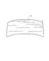
図5に示されるように、画像表示装置4は、ソフトウェア構成(機能構成)として、画像表示制御部41を含む。画像表示制御部41は、画像提供装置1より提供された前記海底形状の仮想空間画像を表示装置24からの風景の海面下に重畳して表示する。図6は、海底形状の仮想空間画像を表示装置24からの風景の海面下に重畳して表示した一例を示す図である。例えば、図6では、海底の岩として51と、52と、が船首のフロントガラスに前記フロントガラスからの風景に重畳して表示されている。上述したような強調表示を行う構成とした場合、船体最下部から所定距離内に海底の岩51が存在した場合、海底の岩51は、海底の岩52に比べて強調表示される。なお、強調表示の一例としては、岩52の近くに「衝突の危険!」等と文字列を表示させてもよいし、岩52を赤く縁取る等してもよい。
FIG. 5 is a diagram illustrating an example of a software configuration of the
As illustrated in FIG. 5, the
以上、本実施形態によれば、船舶が航行する際に有益な情報を、船員等が直感的に状況を把握可能に提供することができる。 As described above, according to the present embodiment, it is possible to provide useful information when a ship sails so that a sailor or the like can intuitively grasp the situation.
<実施形態2>
以下、実施形態2を説明する。実施形態2では、実施形態1とは異なる点を主に説明する。
図7は、実施形態2の画像表示システムのシステム構成の一例を示す図である。図7に示されるように、実施形態2の画像表示システムは、実施形態1の画像表示システムに比べて、レーダー装置の一例であるレーダー8が新たに画像表示システムに含まれている。
実施形態2の画像提供装置1は、レーダー8のレーダーのエコーに基づく海面下の画像と、前記電子海図と、を比較し、前記電子海図に載っていない障害物を前記海面下に検知した場合、前記障害物を含む前記海底形状の仮想空間画像を作成し、画像表示装置4に提供する。
実施形態2の構成によれば、電子海図に載っていない沈没船やケーソン等の障害物を検知し、前記障害物を表示装置24からの風景の海面下に重畳して表示することができる。
なお、図7のレーダー8は、魚群探知機であってもよい。この様な構成によれば、くじら等、船舶の航行の障害となるような海洋生物を含む海底形状の仮想空間画像を作成し、表示装置24からの風景の海面下に重畳して表示することができる。
<Embodiment 2>
Hereinafter, Embodiment 2 will be described. In the second embodiment, differences from the first embodiment will be mainly described.
FIG. 7 is a diagram illustrating an example of a system configuration of the image display system according to the second embodiment. As shown in FIG. 7, the image display system according to the second embodiment includes a
When the
According to the configuration of the second embodiment, an obstacle such as a sunken ship or a caisson that is not on the electronic chart can be detected, and the obstacle can be displayed superimposed on the sea surface of the landscape from the
Note that the
<実施形態3>
以下、実施形態3を説明する。実施形態3では、上述した実施形態とは異なる点を主に説明する。
図8は、実施形態3の画像表示システムのシステム構成の一例を示す図である。図8に示されるように、実施形態3の画像表示システムは、実施形態1の画像表示システムに比べて、検知装置の一例として船舶の姿勢を検知するジャイロセンサー9が新たに画像表示システムに含まれている。
実施形態3の画像提供装置1は、ジャイロセンサー9で検知された船舶の姿勢に基づいて、作成した海底形状の仮想空間画像の海面と前記画像表示装置からの風景の海面とが水平になるよう座標変換を行い、画像表示装置4に提供する。
実施形態3の構成によれば、船舶が揺れた状態でも、フロントガラスには実際の海面と前記海底形状の仮想空間画像の海面とが一致して表示される。
<Embodiment 3>
Hereinafter, Embodiment 3 will be described. In the third embodiment, differences from the above-described embodiment will be mainly described.
FIG. 8 is a diagram illustrating an example of a system configuration of the image display system according to the third embodiment. As shown in FIG. 8, the image display system of the third embodiment includes a gyro sensor 9 that detects the attitude of the ship as an example of a detection device, as compared with the image display system of the first embodiment. It is.
The
According to the configuration of the third embodiment, even when the ship is shaken, the actual sea surface and the sea surface of the virtual space image of the seabed shape are displayed on the windshield in a consistent manner.
<実施形態4>
以下、実施形態4を説明する。実施形態4では、上述した実施形態とは異なる点を主に説明する。
図9は、実施形態4の画像表示システムのシステム構成の一例を示す図である。図9に示されるように、実施形態4の画像表示システムは、実施形態1の画像表示システムに比べて、情報を受信する受信装置10が新たに画像表示システムに含まれている。
受信装置10は、船舶が存在する海域の他の船舶に関する情報を例えば海上交通センター等から受信する。
実施形態4の画像提供装置1は、受信装置10で受信された前記他の船舶に関する情報を含む仮想空間画像を作成し、画像表示装置4に提供する。
画像表示装置4は、画像提供装置1より提供された、前記海底形状の仮想空間画像と、前記他の船舶に関する情報を含む仮想空間画像と、を表示装置24からの風景に重畳して表示する。
実施形態4の構成によれば、船員等は、濃霧時等でも他船の大きさや動き等他の船舶に関する情報を直感的に認識することができる。
<
FIG. 9 is a diagram illustrating an example of a system configuration of the image display system according to the fourth embodiment. As illustrated in FIG. 9, the image display system according to the fourth embodiment includes a receiving device 10 that receives information, as compared with the image display system according to the first embodiment.
The receiving device 10 receives information about other ships in the sea area where the ship is present from, for example, a maritime traffic center.
The
The
According to the configuration of the fourth embodiment, sailors and the like can intuitively recognize information related to other ships such as the size and movement of other ships even during heavy fog.
<実施形態5>
以下、実施形態5を説明する。実施形態5では、上述した実施形態とは異なる点を主に説明する。
図10は、実施形態5の画像表示システムのシステム構成の一例を示す図である。図10に示されるように、実施形態5の画像表示システムは、実施形態1の画像表示システムに比べて、レーダー8と、情報を受信する受信装置10と、が新たに画像表示システムに含まれている。
実施形態5の受信装置10は、他の船舶が取得した前記他の船舶のレーダーのエコーと、その船舶がエコーを検知した位置情報とを前記他の船舶より受信する。
そして、実施形態5の画像提供装置1は、レーダー8のエコーに基づく画像と受信装置10で受信された前記他の船舶のレーダーのエコーに基づく画像とを比較することで、レーダー8のエコーで検知した障害物とレーダー8のエコーでは検知できなかった障害物とを含む仮想空間画像を作成し、作成した仮想空間画像を画像表示装置4に提供する。この際、他の船舶のレーダーのエコー画像は、当該船舶がエコーを検知した位置に基づいて生成されている為、受信した位置情報を用いて自船のレーダー8で検知した画像と位置合わせした上で比較する。
画像表示装置4は、画像提供装置1より提供された、前記海底形状の仮想空間画像と、レーダー8のエコーで検知した障害物とレーダー8のエコーでは検知できなかった障害物とを含む仮想空間画像と、を表示装置24からの風景に重畳して表示する。
実施形態5の構成によれば、他船で捉えたレーダーのエコーを受信し、自船のレーダーのエコーと、を重ね合わせて差異をとることで、自船で捉えられなかった障害物(船舶、岩礁、鯨等の海洋生物等)を識別して、前記障害物を含む仮想空間画像を作成し、表示させることができる。
<Embodiment 5>
Embodiment 5 will be described below. In the fifth embodiment, differences from the above-described embodiment will be mainly described.
FIG. 10 is a diagram illustrating an example of a system configuration of the image display system according to the fifth embodiment. As shown in FIG. 10, the image display system according to the fifth embodiment includes a
The receiving device 10 according to the fifth embodiment receives the radar echo of the other ship acquired by the other ship and the position information at which the ship has detected the echo from the other ship.
Then, the
The
According to the configuration of the fifth embodiment, obstacles that could not be captured by the ship (ships) can be obtained by receiving the echoes of the radar captured by the other ship and superimposing the radar echoes of the ship. And a virtual space image including the obstacle can be created and displayed.
上述した各実施形態によれば、船舶が航行する際に有益な情報を、船員等が直感的に状況を把握可能に提供することができる。 According to each embodiment mentioned above, useful information can be provided when a ship sails so that a crew member etc. can grasp a situation intuitively.
以上、本発明の好ましい実施形態について詳述したが、本発明は係る特定の実施形態に限定されるものではなく、特許請求の範囲に記載された本発明の要旨の範囲内において、種々の変形・変更が可能である。
例えば、上述した実施形態では、透過型液晶フィルムを貼り付けた窓等、所謂、人体非装着の透過型ディスプレイを例に説明を行ったが、Head Mounted Display等、人体装着の透過型ディスプレイであってもよい。また、画像表示装置4は、船員等が保持する携帯型の透過型、又は非透過型のディスプレイであってもよい。なお、非透過型のディスプレイの場合、非透過型のディスプレイは、撮像装置で撮像された画像と、仮想空間画像と、を重畳して表示することになる。
また、上述した実施形態では、画像表示装置4を例に説明を行ったが、例えば、低反射フィルムを貼り付けた窓等へ仮想空間画像を投影するプロジェクタであってもよい。
なお、上述した実施形態を任意に組み合わせて実施してもよい。
The preferred embodiments of the present invention have been described in detail above, but the present invention is not limited to such specific embodiments, and various modifications can be made within the scope of the gist of the present invention described in the claims.・ Change is possible.
For example, in the above-described embodiment, a so-called non-human transmissive display such as a window having a transmissive liquid crystal film attached thereto has been described as an example. However, a transmissive display mounted on a human body such as Head Mounted Display is used. May be. The
In the above-described embodiment, the
In addition, you may implement combining embodiment mentioned above arbitrarily.
1 画像提供装置
4 画像表示装置
1 Image providing
Claims (8)
前記画像提供装置は、前記位置情報取得装置で取得された前記船舶の位置情報と、前記潮位表と、電子海図の示す水深に関する情報と、に基づいて、前記船舶の位置の海面下の深度を求め、更に、前記位置情報取得装置で取得された前記船舶の位置情報に基づいて特定される前記画像表示装置の位置情報と、前記向き取得装置で取得された向きと、前記画像表示装置の大きさと、に基づいて、前記画像表示装置からの視野を特定し、特定した視野と、前記海面下の深度と、前記電子海図の示す海底地形画像データと、に基づいて、前記視野内の前記深度の海面下の海底形状の仮想空間画像を作成し、前記画像表示装置に提供し、
前記画像表示装置は、前記画像提供装置より提供された海底形状の仮想空間画像を前記画像表示装置からの風景に重畳して表示する画像表示システム。 A position information acquisition device for acquiring position information of a ship, an information storage device for storing an electronic chart including a seabed shape and a tide table, an image display device, and an image providing device for providing an image to the image display device; An orientation acquisition device that acquires the orientation of the ship, and an image display system comprising:
The image providing device calculates the depth of the ship below the sea level based on the position information of the ship acquired by the position information acquisition apparatus, the tide table, and information on the water depth indicated by the electronic chart. Further, the position information of the image display device specified based on the position information of the ship acquired by the position information acquisition device, the direction acquired by the direction acquisition device, and the size of the image display device And, based on the identified visual field, the depth below the sea level, and the seafloor topographic image data indicated by the electronic chart, the depth within the visual field. Create a virtual space image of the shape of the seabed under the sea surface and provide it to the image display device,
The image display device is an image display system that displays a sea-bottom-shaped virtual space image provided by the image providing device superimposed on a landscape from the image display device.
前記画像提供装置は、前記レーダー装置のエコーに基づく海面下の画像と、前記電子海図の示す海底地形画像データと、を比較し、前記電子海図に載っていない障害物を前記海面下に検知した場合、前記障害物を含む前記海面下の海底形状の仮想空間画像を作成し、前記画像表示装置に提供する請求項1又は2記載の画像表示システム。 A radar device;
The image providing device compares an undersea image based on an echo of the radar device with seafloor topographic image data indicated by the electronic chart, and detects an obstacle not on the electronic chart under the sea surface. 3. The image display system according to claim 1, wherein a virtual space image of the undersea surface including the obstacle is created and provided to the image display device.
前記画像提供装置は、前記検知装置で検知された前記船舶の姿勢に基づいて、前記作成
した海底形状の仮想空間画像の海面を前記画像表示装置からの風景の海面と水平になるよう座標変換を行い、前記画像表示装置に提供する請求項1乃至3何れか1項記載の画像表示システム。 Further comprising a detection device for detecting the attitude of the ship;
The image providing device performs coordinate conversion based on the attitude of the ship detected by the detection device so that the sea surface of the created seabed-shaped virtual space image is horizontal with the sea surface of the landscape from the image display device. The image display system according to claim 1, wherein the image display system is provided and provided to the image display device.
前記受信装置は、前記船舶が存在する海域の他の船舶の情報を海上交通センターから受信し、
前記画像提供装置は、前記受信装置で受信された前記他の船舶の情報を含む仮想空間画像を作成し、前記画像表示装置に提供し、
前記画像表示装置は、前記画像提供装置より提供された、前記海底形状の仮想空間画像と、前記他の船舶の情報を含む仮想空間画像と、を前記画像表示装置からの風景に重畳して表示する請求項1乃至4何れか1項記載の画像表示システム。 A receiving device for receiving information;
The receiving device receives information of other ships in the sea area where the ship exists from a maritime traffic center,
The image providing device creates a virtual space image including information on the other ship received by the receiving device, and provides the virtual image to the image display device.
The image display device superimposes and displays the sea-bottom-shaped virtual space image provided by the image providing device and the virtual space image including information on the other ship on the landscape from the image display device. The image display system according to any one of claims 1 to 4.
情報を受信する受信装置と、
を更に有し、
前記受信装置は、他の船舶が取得した前記他の船舶のレーダー装置のエコーを前記他の船舶より受信し、
前記画像提供装置は、前記レーダー装置のエコーに基づく画像と前記受信装置で受信された前記他の船舶のレーダー装置のエコーに基づく画像とを比較することで、前記レーダー装置のエコーで検知した障害物と前記レーダー装置のエコーでは検知できなかった障害物とを含む仮想空間画像を作成し、作成した仮想空間画像を前記画像表示装置に提供し、
前記画像表示装置は、前記画像提供装置より提供された、前記海底形状の仮想空間画像と、前記レーダー装置のエコーで検知した障害物と前記レーダー装置のエコーでは検知できなかった障害物とを含む仮想空間画像と、を前記画像表示装置からの風景に重畳して表示する請求項1乃至5何れか1項記載の画像表示システム。 A radar device;
A receiving device for receiving information ;
Further comprising a,
The receiving device receives the echo of the radar device of the other vessel acquired by the other vessel from the other vessel,
The image providing device compares the image based on the echo of the radar device with the image based on the echo of the radar device of the other ship received by the receiving device, thereby detecting the failure detected by the echo of the radar device. Creating a virtual space image including an object and an obstacle that could not be detected by the echo of the radar device, providing the created virtual space image to the image display device;
The image display device includes a virtual space image of the seabed shape provided by the image providing device, an obstacle detected by an echo of the radar device, and an obstacle that cannot be detected by an echo of the radar device. The image display system according to claim 1, wherein a virtual space image is displayed superimposed on a landscape from the image display device.
前記画像提供装置が、前記位置情報取得装置で取得された前記船舶の位置情報と、前記潮位表と、電子海図の示す水深に関する情報と、に基づいて、前記船舶の位置の海面下の深度を求め、更に、前記位置情報取得装置で取得された前記船舶の位置情報に基づいて特定される前記画像表示装置の位置情報と、前記向き取得装置で取得された向きと、前記画像表示装置の大きさと、に基づいて、前記画像表示装置からの視野を特定し、特定した視野と、前記海面下の深度と、前記電子海図の示す海底地形画像データと、に基づいて、前記視野内の前記深度の海面下の海底形状の仮想空間画像を作成し、前記画像表示装置に提供するステップと、
前記画像表示装置が、前記画像提供装置より提供された海底形状の仮想空間画像を前記画像表示装置からの風景に重畳して表示するステップと、
を含む画像表示方法。 A position information acquisition device for acquiring position information of a ship, an information storage device for storing an electronic chart including a seabed shape and a tide table, an image display device, and an image providing device for providing an image to the image display device; An image acquisition method in an image display system including an orientation acquisition device that acquires the orientation of the ship,
Based on the position information of the ship acquired by the position information acquisition apparatus, the tide level table, and information on the water depth indicated by the electronic chart, the image providing apparatus calculates the depth below the sea level of the position of the ship. Further, the position information of the image display device specified based on the position information of the ship acquired by the position information acquisition device, the direction acquired by the direction acquisition device, and the size of the image display device And, based on the identified visual field, the depth below the sea level, and the seafloor topographic image data indicated by the electronic chart, the depth within the visual field. Creating a virtual space image of the shape of the seabed under the sea surface and providing it to the image display device;
The image display device superimposing and displaying a sea-bottom-shaped virtual space image provided by the image providing device on a landscape from the image display device;
An image display method including:
前記位置情報取得装置で取得された船舶の位置情報と、前記潮位表と、電子海図の示す水深に関する情報とに基づいて、前記船舶の位置の海面下の深度を求める計測ステップと、
前記位置情報取得装置で取得された前記船舶の位置情報に基づいて特定される前記画像表示装置の位置情報と、前記向き取得装置で取得された向きと、前記画像表示装置の大きさと、に基づいて、前記画像表示装置からの視野を特定する特定ステップと、
前記特定ステップで特定された視野と、前記計測ステップで求められた海面下の深度と、前記電子海図の示す海底地形画像データと、に基づいて、前記視野内の前記深度の海面下の海底形状の仮想空間画像を作成し、前記仮想空間画像を画像表示装置からの風景に重畳して表示する画像表示装置に提供するステップと、
を実行させるためのプログラム。 A position information acquisition device that acquires position information of a ship, an information storage device that stores an electronic chart including a seafloor shape and a tide table, an image display device, a computer that provides an image to the image display device, and the ship An orientation acquisition device for acquiring the orientation of the image display system including the computer,
The position information of the ship acquired by the position information acquisition device, and the tide level table, and measurement steps on the basis of the information about the depth indicated by the electronic chart to determine the depth of the underwater position of the marine vessel,
Based the position information of the image display apparatus specified based on the position information of the marine vessel that is acquired by the position information acquisition device, and to the orientation obtained by the orientation obtaining unit, to a size of the image display device And a specific step of specifying a visual field from the image display device,
And the field specified in the specifying step, the a depth below sea level obtained in the measurement step, and bathymetric image data indicated by the electronic chart, based on the seabed shape of underwater of the depth within the field of view Providing a virtual space image to an image display device that displays the virtual space image superimposed on a landscape from the image display device;
A program for running
Priority Applications (19)
| Application Number | Priority Date | Filing Date | Title |
|---|---|---|---|
| JP2011055410A JP5102886B2 (en) | 2010-03-30 | 2011-03-14 | Image display system, image display method, and program |
| MYPI2014000892A MY174603A (en) | 2010-03-30 | 2011-03-30 | Information processing apparatus, system, vacant space guidance method and program |
| US13/635,370 US8896685B2 (en) | 2010-03-14 | 2011-03-30 | Method and system for determining information relating to vacant spaces of a parking lot |
| EP20140161561 EP2752805A1 (en) | 2010-03-30 | 2011-03-30 | Information processing apparatus, information processing method and program |
| SG10201400949SA SG10201400949SA (en) | 2010-03-30 | 2011-03-30 | Information Processing System, Information Processing Method And Program, Information Processing Apparatus, Vacant Space Guidance System, Vacant Space Guidance Method And Program, Image Display System, And Image Display Method And Program |
| MYPI2014000893A MY174604A (en) | 2010-03-30 | 2011-03-30 | Information processing apparatus, system, vacant space guidance method and program |
| MYPI2012004283A MY156130A (en) | 2010-03-30 | 2011-03-30 | Information processing apparatus, system, vacant space guidance method and program |
| MYPI2014000891A MY173040A (en) | 2010-03-30 | 2011-03-30 | Information processing apparatus, system, vacant space guidance method and program |
| SG10201400952WA SG10201400952WA (en) | 2010-03-30 | 2011-03-30 | Information Processing System, Information Processing Method And Program, Information Processing Apparatus, Vacant Space Guidance System, Vacant Space Guidance Method And Program, Image Display System, Image Display Method And Program |
| EP20140161557 EP2757517A1 (en) | 2010-03-30 | 2011-03-30 | Information processing apparatus, information processing method and program |
| EP20110762878 EP2544138A4 (en) | 2010-03-30 | 2011-03-30 | Information processing device, information processing method and program, information processing device, vacant space guidance system, vacant space guidance method and program, image displaying system, and image displaying method and program |
| PCT/JP2011/057972 WO2011122654A1 (en) | 2010-03-30 | 2011-03-30 | Information processing device, information processing method and program, information processing device, vacant space guidance system, vacant space guidance method and program, image displaying system, and image displaying method and program |
| EP14161554.2A EP2752362B1 (en) | 2010-03-30 | 2011-03-30 | Image display system, image display method and program |
| SG10201400956YA SG10201400956YA (en) | 2010-03-30 | 2011-03-30 | Information processing system, information processing method and program, information processing apparatus, vacant space guidance system, vacant space guidance method and program, image display system, image display method and program |
| SG2012071809A SG184301A1 (en) | 2010-03-30 | 2011-03-30 | Information processing apparatus, information processing method and program, information processing apparatus, vacant space guidance system, vacant space guidance method and program, image display system, image display method and program |
| US14/228,176 US20140214606A1 (en) | 2010-03-30 | 2014-03-27 | Information processing apparatus, information processing method and program, information processing apparatus, vacant space guidance system, vacant space guidance method and program, image display system, image display method and program |
| US14/228,168 US9395195B2 (en) | 2010-03-30 | 2014-03-27 | System, method and program for managing and displaying product information |
| US14/228,159 US9689688B2 (en) | 2010-03-30 | 2014-03-27 | Image display system, image display method and program |
| US14/521,259 US20150112586A1 (en) | 2010-03-30 | 2014-10-22 | Method and system for determining information relating to vacant spaces of a parking lot |
Applications Claiming Priority (3)
| Application Number | Priority Date | Filing Date | Title |
|---|---|---|---|
| JP2010078973 | 2010-03-30 | ||
| JP2010078973 | 2010-03-30 | ||
| JP2011055410A JP5102886B2 (en) | 2010-03-30 | 2011-03-14 | Image display system, image display method, and program |
Publications (3)
| Publication Number | Publication Date |
|---|---|
| JP2011225208A JP2011225208A (en) | 2011-11-10 |
| JP2011225208A5 JP2011225208A5 (en) | 2012-03-22 |
| JP5102886B2 true JP5102886B2 (en) | 2012-12-19 |
Family
ID=45041123
Family Applications (1)
| Application Number | Title | Priority Date | Filing Date |
|---|---|---|---|
| JP2011055410A Active JP5102886B2 (en) | 2010-03-14 | 2011-03-14 | Image display system, image display method, and program |
Country Status (1)
| Country | Link |
|---|---|
| JP (1) | JP5102886B2 (en) |
Families Citing this family (8)
| Publication number | Priority date | Publication date | Assignee | Title |
|---|---|---|---|---|
| CN102873351B (en) * | 2011-07-13 | 2015-04-22 | 上海胜僖汽车配件有限公司 | Lathe tool |
| EP2666709A1 (en) * | 2012-05-25 | 2013-11-27 | ABB Research Ltd. | A ship having a window as computer user interface |
| KR102376272B1 (en) * | 2015-11-30 | 2022-03-18 | 대우조선해양 주식회사 | Integrated apparatus for bidirectional navigation of vessel |
| JP6673699B2 (en) * | 2016-01-13 | 2020-03-25 | 株式会社パスコ | Terrain display system |
| JP6901306B2 (en) * | 2017-03-31 | 2021-07-14 | 三菱重工業株式会社 | Information projection system and information projection method |
| EP3627479A1 (en) * | 2018-09-19 | 2020-03-25 | Offshore Certification Ltd. | A system for simulating a maritime environment |
| JP6595690B1 (en) * | 2018-11-20 | 2019-10-23 | 五洋建設株式会社 | Method for installation of self-raising work platform and system for installation of self-raising work platform |
| WO2021049221A1 (en) | 2019-09-09 | 2021-03-18 | 古野電気株式会社 | Ship information display system, ship information display method, image generation device, and program |
Family Cites Families (2)
| Publication number | Priority date | Publication date | Assignee | Title |
|---|---|---|---|---|
| JP2543711Y2 (en) * | 1989-11-30 | 1997-08-13 | 株式会社島津製作所 | Head-up display |
| JP2004212192A (en) * | 2002-12-27 | 2004-07-29 | Senaa Kk | Maneuvering support system, maneuvering support program, and three-dimensional image generation method for maneuvering support |
-
2011
- 2011-03-14 JP JP2011055410A patent/JP5102886B2/en active Active
Also Published As
| Publication number | Publication date |
|---|---|
| JP2011225208A (en) | 2011-11-10 |
Similar Documents
| Publication | Publication Date | Title |
|---|---|---|
| US10942028B2 (en) | Video sensor fusion and model based virtual and augmented reality systems and methods | |
| US11328155B2 (en) | Augmented reality labels systems and methods | |
| JP5102886B2 (en) | Image display system, image display method, and program | |
| JP6293960B1 (en) | Collision avoidance support system | |
| US20210206459A1 (en) | Video sensor fusion and model based virtual and augmented reality systems and methods | |
| GB2601644A (en) | Video and image chart fusion systems and methods | |
| KR101549513B1 (en) | System and Method for Preventing Collision of Vessel and Recording using Augmented Reality | |
| US11892298B2 (en) | Navigational danger identification and feedback systems and methods | |
| KR20110116842A (en) | Electronic navigational chart display method of vessels navigation system using augmented reality | |
| JPH06301897A (en) | Navigation supporting device for vessel | |
| KR20210046500A (en) | Apparatus and Method for Automatic Sailing of Ship and Recording Medium | |
| JP2022173157A (en) | Tidal current information display device | |
| JP2022173147A (en) | Tide information display device | |
| CN111357281B (en) | Video generating device and video generating method | |
| WO2018102772A1 (en) | System and method for augmented reality comprising labels | |
| JP2020095333A (en) | Method for determining obstacle zone by target, system for mobile body, and method for displaying obstacle zone by target | |
| JP2004212192A (en) | Maneuvering support system, maneuvering support program, and three-dimensional image generation method for maneuvering support | |
| US11808579B2 (en) | Augmented reality based tidal current display apparatus and method | |
| JP2021146778A (en) | Sailing route generation device | |
| EP3663188A1 (en) | Head mounted display system | |
| Templin et al. | Using Augmented and Virtual Reality (AR/VR) to Support Safe Navigation on Inland and Coastal Water Zones. Remote Sens. 2022, 14, 1520 | |
| Makino et al. | Information System for Achieving Navigational Safety by Obtaining Visual Information Using a 360 Camera | |
| SE524877C2 (en) | Navigation system for boats, displays suggested route taking into account water level, depth of boat in water and swell height |
Legal Events
| Date | Code | Title | Description |
|---|---|---|---|
| A521 | Request for written amendment filed |
Free format text: JAPANESE INTERMEDIATE CODE: A523 Effective date: 20120206 |
|
| A621 | Written request for application examination |
Free format text: JAPANESE INTERMEDIATE CODE: A621 Effective date: 20120206 |
|
| A871 | Explanation of circumstances concerning accelerated examination |
Free format text: JAPANESE INTERMEDIATE CODE: A871 Effective date: 20120206 |
|
| A975 | Report on accelerated examination |
Free format text: JAPANESE INTERMEDIATE CODE: A971005 Effective date: 20120224 |
|
| A131 | Notification of reasons for refusal |
Free format text: JAPANESE INTERMEDIATE CODE: A131 Effective date: 20120612 |
|
| A521 | Request for written amendment filed |
Free format text: JAPANESE INTERMEDIATE CODE: A523 Effective date: 20120808 |
|
| TRDD | Decision of grant or rejection written | ||
| A01 | Written decision to grant a patent or to grant a registration (utility model) |
Free format text: JAPANESE INTERMEDIATE CODE: A01 Effective date: 20120918 |
|
| A01 | Written decision to grant a patent or to grant a registration (utility model) |
Free format text: JAPANESE INTERMEDIATE CODE: A01 |
|
| A61 | First payment of annual fees (during grant procedure) |
Free format text: JAPANESE INTERMEDIATE CODE: A61 Effective date: 20120928 |
|
| FPAY | Renewal fee payment (event date is renewal date of database) |
Free format text: PAYMENT UNTIL: 20151005 Year of fee payment: 3 |
|
| R150 | Certificate of patent or registration of utility model |
Ref document number: 5102886 Country of ref document: JP Free format text: JAPANESE INTERMEDIATE CODE: R150 Free format text: JAPANESE INTERMEDIATE CODE: R150 |
|
| FPAY | Renewal fee payment (event date is renewal date of database) |
Free format text: PAYMENT UNTIL: 20151005 Year of fee payment: 3 |
|
| R250 | Receipt of annual fees |
Free format text: JAPANESE INTERMEDIATE CODE: R250 |
|
| R250 | Receipt of annual fees |
Free format text: JAPANESE INTERMEDIATE CODE: R250 |
|
| R250 | Receipt of annual fees |
Free format text: JAPANESE INTERMEDIATE CODE: R250 |
|
| R250 | Receipt of annual fees |
Free format text: JAPANESE INTERMEDIATE CODE: R250 |
|
| R250 | Receipt of annual fees |
Free format text: JAPANESE INTERMEDIATE CODE: R250 |
|
| R250 | Receipt of annual fees |
Free format text: JAPANESE INTERMEDIATE CODE: R250 |
|
| R250 | Receipt of annual fees |
Free format text: JAPANESE INTERMEDIATE CODE: R250 |
|
| R250 | Receipt of annual fees |
Free format text: JAPANESE INTERMEDIATE CODE: R250 |
|
| R250 | Receipt of annual fees |
Free format text: JAPANESE INTERMEDIATE CODE: R250 |