JP5102285B2 - Dosage counter - Google Patents
Dosage counter Download PDFInfo
- Publication number
- JP5102285B2 JP5102285B2 JP2009506785A JP2009506785A JP5102285B2 JP 5102285 B2 JP5102285 B2 JP 5102285B2 JP 2009506785 A JP2009506785 A JP 2009506785A JP 2009506785 A JP2009506785 A JP 2009506785A JP 5102285 B2 JP5102285 B2 JP 5102285B2
- Authority
- JP
- Japan
- Prior art keywords
- cone
- rotation
- ring
- unit
- tens
- Prior art date
- Legal status (The legal status is an assumption and is not a legal conclusion. Google has not performed a legal analysis and makes no representation as to the accuracy of the status listed.)
- Active
Links
Images


Classifications
-
- A—HUMAN NECESSITIES
- A61—MEDICAL OR VETERINARY SCIENCE; HYGIENE
- A61M—DEVICES FOR INTRODUCING MEDIA INTO, OR ONTO, THE BODY; DEVICES FOR TRANSDUCING BODY MEDIA OR FOR TAKING MEDIA FROM THE BODY; DEVICES FOR PRODUCING OR ENDING SLEEP OR STUPOR
- A61M15/00—Inhalators
- A61M15/0065—Inhalators with dosage or measuring devices
-
- A—HUMAN NECESSITIES
- A61—MEDICAL OR VETERINARY SCIENCE; HYGIENE
- A61M—DEVICES FOR INTRODUCING MEDIA INTO, OR ONTO, THE BODY; DEVICES FOR TRANSDUCING BODY MEDIA OR FOR TAKING MEDIA FROM THE BODY; DEVICES FOR PRODUCING OR ENDING SLEEP OR STUPOR
- A61M15/00—Inhalators
- A61M15/009—Inhalators using medicine packages with incorporated spraying means, e.g. aerosol cans
-
- A—HUMAN NECESSITIES
- A61—MEDICAL OR VETERINARY SCIENCE; HYGIENE
- A61M—DEVICES FOR INTRODUCING MEDIA INTO, OR ONTO, THE BODY; DEVICES FOR TRANSDUCING BODY MEDIA OR FOR TAKING MEDIA FROM THE BODY; DEVICES FOR PRODUCING OR ENDING SLEEP OR STUPOR
- A61M15/00—Inhalators
- A61M15/0065—Inhalators with dosage or measuring devices
- A61M15/0068—Indicating or counting the number of dispensed doses or of remaining doses
- A61M15/007—Mechanical counters
- A61M15/0071—Mechanical counters having a display or indicator
- A61M15/0073—Mechanical counters having a display or indicator on a ring
-
- A—HUMAN NECESSITIES
- A61—MEDICAL OR VETERINARY SCIENCE; HYGIENE
- A61M—DEVICES FOR INTRODUCING MEDIA INTO, OR ONTO, THE BODY; DEVICES FOR TRANSDUCING BODY MEDIA OR FOR TAKING MEDIA FROM THE BODY; DEVICES FOR PRODUCING OR ENDING SLEEP OR STUPOR
- A61M15/00—Inhalators
- A61M15/0065—Inhalators with dosage or measuring devices
- A61M15/0068—Indicating or counting the number of dispensed doses or of remaining doses
- A61M15/007—Mechanical counters
- A61M15/0071—Mechanical counters having a display or indicator
- A61M15/0075—Mechanical counters having a display or indicator on a disc
-
- B—PERFORMING OPERATIONS; TRANSPORTING
- B65—CONVEYING; PACKING; STORING; HANDLING THIN OR FILAMENTARY MATERIAL
- B65D—CONTAINERS FOR STORAGE OR TRANSPORT OF ARTICLES OR MATERIALS, e.g. BAGS, BARRELS, BOTTLES, BOXES, CANS, CARTONS, CRATES, DRUMS, JARS, TANKS, HOPPERS, FORWARDING CONTAINERS; ACCESSORIES, CLOSURES, OR FITTINGS THEREFOR; PACKAGING ELEMENTS; PACKAGES
- B65D83/00—Containers or packages with special means for dispensing contents
- B65D83/14—Containers or packages with special means for dispensing contents for delivery of liquid or semi-liquid contents by internal gaseous pressure, i.e. aerosol containers comprising propellant for a product delivered by a propellant
- B65D83/44—Valves specially adapted therefor; Regulating devices
- B65D83/46—Tilt valves
-
- B—PERFORMING OPERATIONS; TRANSPORTING
- B65—CONVEYING; PACKING; STORING; HANDLING THIN OR FILAMENTARY MATERIAL
- B65D—CONTAINERS FOR STORAGE OR TRANSPORT OF ARTICLES OR MATERIALS, e.g. BAGS, BARRELS, BOTTLES, BOXES, CANS, CARTONS, CRATES, DRUMS, JARS, TANKS, HOPPERS, FORWARDING CONTAINERS; ACCESSORIES, CLOSURES, OR FITTINGS THEREFOR; PACKAGING ELEMENTS; PACKAGES
- B65D83/00—Containers or packages with special means for dispensing contents
- B65D83/14—Containers or packages with special means for dispensing contents for delivery of liquid or semi-liquid contents by internal gaseous pressure, i.e. aerosol containers comprising propellant for a product delivered by a propellant
- B65D83/44—Valves specially adapted therefor; Regulating devices
- B65D83/52—Valves specially adapted therefor; Regulating devices for metering
- B65D83/54—Metering valves ; Metering valve assemblies
-
- B—PERFORMING OPERATIONS; TRANSPORTING
- B65—CONVEYING; PACKING; STORING; HANDLING THIN OR FILAMENTARY MATERIAL
- B65D—CONTAINERS FOR STORAGE OR TRANSPORT OF ARTICLES OR MATERIALS, e.g. BAGS, BARRELS, BOTTLES, BOXES, CANS, CARTONS, CRATES, DRUMS, JARS, TANKS, HOPPERS, FORWARDING CONTAINERS; ACCESSORIES, CLOSURES, OR FITTINGS THEREFOR; PACKAGING ELEMENTS; PACKAGES
- B65D83/00—Containers or packages with special means for dispensing contents
- B65D83/14—Containers or packages with special means for dispensing contents for delivery of liquid or semi-liquid contents by internal gaseous pressure, i.e. aerosol containers comprising propellant for a product delivered by a propellant
- B65D83/75—Aerosol containers not provided for in groups B65D83/16 - B65D83/74
-
- G—PHYSICS
- G06—COMPUTING; CALCULATING OR COUNTING
- G06M—COUNTING MECHANISMS; COUNTING OF OBJECTS NOT OTHERWISE PROVIDED FOR
- G06M1/00—Design features of general application
- G06M1/14—Design features of general application for transferring a condition from one stage to a higher stage
- G06M1/16—Design features of general application for transferring a condition from one stage to a higher stage self-operating, e.g. by Geneva mechanism
-
- G—PHYSICS
- G06—COMPUTING; CALCULATING OR COUNTING
- G06M—COUNTING MECHANISMS; COUNTING OF OBJECTS NOT OTHERWISE PROVIDED FOR
- G06M1/00—Design features of general application
- G06M1/22—Design features of general application for visual indication of the result of count on counting mechanisms, e.g. by window with magnifying lens
- G06M1/24—Drums; Dials; Pointers
Landscapes
- Engineering & Computer Science (AREA)
- Health & Medical Sciences (AREA)
- Life Sciences & Earth Sciences (AREA)
- Dispersion Chemistry (AREA)
- Chemical & Material Sciences (AREA)
- General Health & Medical Sciences (AREA)
- Bioinformatics & Cheminformatics (AREA)
- Hematology (AREA)
- Biomedical Technology (AREA)
- Animal Behavior & Ethology (AREA)
- Anesthesiology (AREA)
- Public Health (AREA)
- Veterinary Medicine (AREA)
- Heart & Thoracic Surgery (AREA)
- Pulmonology (AREA)
- Mechanical Engineering (AREA)
- Biophysics (AREA)
- Theoretical Computer Science (AREA)
- General Physics & Mathematics (AREA)
- Physics & Mathematics (AREA)
- Medical Preparation Storing Or Oral Administration Devices (AREA)
- Infusion, Injection, And Reservoir Apparatuses (AREA)
- Containers And Packaging Bodies Having A Special Means To Remove Contents (AREA)
Abstract
Description
本発明は、薬剤の計量投与に適した装置に関連して用いるための投与量カウンターに関する。 The present invention relates to a dose counter for use in connection with a device suitable for metering a drug.
定量薬剤投与ディスペンサには様々な形があるが、薬剤の所定投与量(即ち、量)が投与量投与操作中に投与される共通点がある。定量薬剤投与ディスペンサの一般的な形の1つとしては吸入器が即知である。吸入器は、喘息の治療およびその他の呼吸器系の病気のために一般に使用されている。 There are various forms of metered dose dispensers, but there is a common point that a predetermined dose (ie, amount) of medication is administered during a dose administration operation. One common form of metered dose dispenser is the inhaler. Inhalers are commonly used for the treatment of asthma and other respiratory diseases.
吸入器は、一般的に、エアゾール容器および容器収納のためのアクチュエータハウジングを有するエアゾール投与アセンブリの形をとる。加圧吸入器の場合、容器は、エアゾールキャニスタを画定するために容器に充填された好適な噴射剤で配合された薬剤を含む。この容器は、一般的に、バルブのようなフェルール、具体的には、閉鎖位置と放出位置との間を移動可能な弁棒を備えた計量バルブを用いて嵌め合わされた薬剤ディスペンサを装備している。薬剤の入った、および容器上にディスペンサを有する当該の容器(即ち、エアゾールキャニスタ)は、従って、薬瓶を画定する。薬瓶は、詰め替え不可能で、その中の薬剤の投与後直ちに処分される。薬瓶は、一般的に、患者ポート(例えば、マウスピースまたは鼻への利用に適した開口部)を有するアクチュエータハウジング(再利用し得る)と併せて利用される。アクチュエータハウジングは、一般的に、薬瓶容器上のバルブの弁棒の収納に適したソケットを有し、ならびにソケットおよび患者ポートに連通する開口部を有する支持ブロックを備える。キャニスタおよび支持ブロックは、アセンブリの動作または投与中に弁棒を放出位置まで移動することを可能にするために、軸線に沿って互いに対して移動可能である。従って、薬瓶から薬剤の投与量を投与する。アクチュエータハウジングは、一般的に、支持ブロックの反対側に伸び、薬瓶容器の少なくとも一部分を収納するチャンバを備える細長い部分をさらに含有する。所望の薬剤投与性能を達成するために(即ち、利用者によってエアゾール投与アセンブリが作動される度に単回の計量量の投与または適切な粒度分布の吹き付け薬剤の投与量の投与)使用されるアクチュエータハウジングおよび薬瓶の多くの関連した設計の特徴がある。 Inhalers generally take the form of an aerosol dispensing assembly having an aerosol container and an actuator housing for container storage. In the case of a pressurized inhaler, the container contains a drug formulated with a suitable propellant filled into the container to define an aerosol canister. This container is typically equipped with a drug dispenser fitted with a ferrule such as a valve, specifically a metering valve with a valve stem movable between a closed position and a discharge position. Yes. The container (ie, aerosol canister) containing the drug and having the dispenser on the container thus defines a vial. The drug bottle is not refillable and is disposed of immediately after administration of the drug therein. The vial is typically utilized in conjunction with an actuator housing (which can be reused) having a patient port (eg, an opening suitable for mouthpiece or nose use). The actuator housing generally comprises a support block having a socket suitable for accommodating a valve stem of a valve on a vial container and having an opening in communication with the socket and patient port. The canister and support block are movable relative to each other along the axis to allow the valve stem to be moved to the release position during operation or administration of the assembly. Therefore, the dose of the drug is administered from the drug bottle. The actuator housing generally further includes an elongated portion that extends opposite the support block and includes a chamber that houses at least a portion of the vial container. Actuator used to achieve the desired drug delivery performance (ie, single dose administration or appropriate size distribution spray drug administration each time the aerosol administration assembly is activated by the user) There are many related design features of the housing and medicine bottle.
薬剤の投与量投与には、吸入器利用者は通常、吸入器を軸線方向に強く押すかまたは押し下げて、支持ブロックへ向かってキャニスタのアクチュエータハウジング内への相対運動をもたらす。吸入器利用者が、吸入器中にどれだけの投与量が残っているかを知ることは有益である(即ち、どれくらいの投与量ごとの薬剤がエアゾール投与アセンブリの容器中にあるのか)。この目的を達成するために、信頼性のある投与量カウンター装置および手法は、エアゾール投与アセンブリより何回の投与量が投与されたのかを記録し、投与するための投与量が何回残っているのかを利用者に知らせるために所望される。 For drug dose administration, the inhaler user typically pushes or pushes the inhaler strongly axially, causing relative movement into the actuator housing of the canister toward the support block. It is beneficial for the inhaler user to know how much dose remains in the inhaler (ie, how much drug is in each dose in the container of the aerosol dosing assembly). To achieve this goal, a reliable dose counter device and technique records how many doses have been administered from the aerosol dosing assembly and how many doses remain to be administered It is desirable to inform the user of whether or not.
国際公開第2005/060535号および国際公開第2004/041334(A2)号にあるように、吸入器と共に使用される投与量カウンターの多くの提案がある(吸入器が、例えば、ドライパウダー吸入器、携帯用ネブライザ、加圧定量投与吸入器、またはその他の種類にかかわらず)。しかし、進歩にもかかわらず、経済的で、信頼性のある投与量カウンターの重要な必要性がある。 As in WO 2005/060535 and WO 2004/041334 (A2), there are many proposals for a dose counter to be used with an inhaler (for example, an inhaler is a dry powder inhaler, Portable nebulizer, pressurized metered dose inhaler, or any other type). However, despite progress, there is an important need for an economical and reliable dose counter.
いくつかの投与量カウンターの構造は、薬剤の投与量が既に投与された場合に限り、確実に単回投与量を測定し得ないことが分かった。バルブを開くために弁棒が十分に押圧されていない場合、測定は始動されるべきではなく、および投与量動作中に1投与量以上測定されるべきではない(例えば、バルブの閉まる動作が中断された場合)。さらに、吸入器が意図されたように機能するには、および、ポケット、ハンドバッグ、通学カバン等に入れて持ち歩く厳しい条件にさらされた場合でも測定が変化しないようにするには、いくつかの投与量カウンターは、製品寿命中、十分に頑丈で安定していない可能性がある。さらに、設計によっては、製造ばらつきを伴ってそれらが使用される製品における通常の製造ばらつきに対して補償する困難さを抱える可能性がある(例えば、許容誤差を有する吸入器は、弁棒の長さのわずかな違いおよび/またはバルブが始動する前の弁棒の移動長さのわずかな違いをもたらす可能性がある)。投与量カウンターがエアゾール吸入器の容器用のハウジングに結合されるとき、複雑さを最小限にしかつ取り付けを容易にする、および可能な限り小型な装置、しかし容易に信頼性および読み取り可能な薬剤投与量カウントを利用者に提供することが望ましい。 It has been found that the structure of some dose counters cannot reliably measure a single dose only if the drug dose has already been administered. If the valve stem is not fully depressed to open the valve, the measurement should not be triggered and more than one dose should not be measured during the dose operation (eg, the valve closing operation is interrupted) If) In addition, several doses are required to ensure that the inhaler functions as intended and that the measurement does not change when exposed to the harsh conditions of being carried in pockets, handbags, school bags, etc. The volume counter may be sufficiently sturdy and unstable during the life of the product. In addition, some designs may have difficulty with manufacturing variations to compensate for normal manufacturing variations in the products in which they are used (for example, inhalers with tolerances have a length of valve stem). A slight difference in length and / or a slight difference in the travel length of the valve stem before the valve is started). When the dose counter is coupled to the housing for the aerosol inhaler container, it minimizes complexity and facilitates installation, and is as small as possible, but easily reliable and readable drug administration It is desirable to provide the user with a quantity count.
一様態において、本発明は、薬剤の計量投与に適した装置に関連して用いるための投与量カウンターを提供する。カウント表示器は、第1カウント表示器および第2カウント表示器を備える。第1カウント表示器は、第1表示体支持面を有し、第1軸線回りに回転可能である。第2カウント表示器は、第2表示体支持面を有し、第2軸線回りに回転可能である。第2軸線は、第1軸線に対して鈍角を成して配置され、第1および第2表示体支持面は、薬剤投与量測定の少なくとも一部分をまとめて示すために、共通視認領域において整列する。 In one aspect, the present invention provides a dose counter for use in connection with a device suitable for metering a drug. The count indicator includes a first count indicator and a second count indicator. The first count indicator has a first display body support surface and is rotatable around the first axis. The second count indicator has a second display body support surface and is rotatable around the second axis. The second axis is disposed at an obtuse angle with respect to the first axis, and the first and second display support surfaces are aligned in a common viewing area to collectively show at least a portion of the drug dosage measurement. .
一様態において、本発明は、薬剤の計量投与に適した装置に関連して用いるための投与量カウンターに関する。カウント表示器は、第1カウント表示器および第2カウント表示器を備える。第1カウント表示器は、第1表示体支持面を有し、第1軸線回りに回転可能である。第2カウント表示器は、第2表示体支持面を有し、第2軸線回りに回転可能である。前記第1および第2軸線は、互いに対して同軸、平行または垂直配列で配置されない。第1および第2表示体支持面は、薬剤投与量測定の少なくとも一部分をまとめて示すために共通視認領域において整列する。 In one aspect, the invention relates to a dose counter for use in connection with a device suitable for metering a drug. The count indicator includes a first count indicator and a second count indicator. The first count indicator has a first display body support surface and is rotatable around the first axis. The second count indicator has a second display body support surface and is rotatable around the second axis. The first and second axes are not arranged in a coaxial, parallel or vertical arrangement with respect to each other. The first and second display support surfaces are aligned in a common viewing area to collectively show at least a portion of the drug dose measurement.
驚くことに、第1および第2カウント表示器の軸線が、互いに対して同軸、平行または垂直配列で配置されておらず、第1カウント表示器が、第2カウント表示器の軸線に対して、軸線上において鈍角(詳細には、90度より大きく180度未満の角度)を成して配置されている第1および第2軸線回りに回転可能な第1および第2カウント表示器の各々を使用することにより、ハウジングの修正を加えずに、または最小の修正(形および/またはサイズ)でハウジング内の利用可能空間に適合する小型測定器を提供することが可能であることが分かった。さらに、同時に、測定器はその小型サイズにより、製品の性能(例えば、吸入器の気流)への影響力がより少ない。さらに、驚くことに、測定器自体が極めて小型であっても、個別の数字での表示または並列した表示を通して、利用者による測定器の読み取りに有利な容易さを提供することが分かった。 Surprisingly, the axes of the first and second count indicators are not arranged in a coaxial, parallel or vertical arrangement with respect to each other, the first count indicator being relative to the axis of the second count indicator, Use each of first and second count indicators that are rotatable about first and second axes that are arranged at an obtuse angle on the axis (specifically, an angle greater than 90 degrees and less than 180 degrees) By doing so, it has been found that it is possible to provide a small measuring instrument that fits the available space in the housing without any modification of the housing or with minimal modifications (shape and / or size). Furthermore, at the same time, the instrument is less influential on product performance (eg, inhaler airflow) due to its small size. Furthermore, it has surprisingly been found that even if the measuring instrument itself is very small, it provides an advantageous ease for the user to read the measuring instrument through individual numerical displays or in parallel displays.
これは、カウント表示器が交差するため、1つのカウント表示器から別のカウント表示器に動作を伝えるための転換ギヤの必要なしに実現した。このような交差は、構造間で周期的に相互作用する構造の設計を可能にした。従って、本明細書で説明される測定器は望ましくは転換ギヤを含まず、これによってここでもまた小型測定器の提供を可能にする。 This was accomplished without the need for a conversion gear to transfer operation from one count indicator to another because the count indicators crossed. Such intersections allowed the design of structures that interact periodically between structures. Thus, the measuring instrument described herein preferably does not include a conversion gear, which again allows the provision of a small measuring instrument.
別の様態において、本発明は、薬剤の計量投与に適した装置に関連して用いるための投与量カウンターである。投与量カウンターは、第1カウント表示器および第2カウント表示器を備える。第1カウント表示器は、軸線回りに回転可能で、軸線に関して円錐面である第1表示体支持面を有する。カウント表示器のうちの一方の動作は、他方のカウント表示器の動作に応じて起動される。第1および第2表示体支持面は、薬剤投与量測定の少なくとも一部分をまとめて示すために、共通視認領域において整列する。 In another aspect, the present invention is a dose counter for use in connection with a device suitable for metering a drug. The dose counter includes a first count indicator and a second count indicator. The first count indicator has a first display support surface that is rotatable about an axis and is conical with respect to the axis. One operation of the count display is activated in response to the operation of the other count display. The first and second display support surfaces are aligned in a common viewing area to collectively show at least a portion of the drug dose measurement.
円錐形の第1カウント表示器の使用は、測定器を収容するために内側面および/または外側面および/またはアクチュエータの体積をほとんど変更せずにもしくは全く変更せずに、安定した方法で、各々の測定器の湾曲側面、詳細には、一般的な吸入器アクチュエータの「エルボーベンド」内への取り付けを容易にする。 The use of a conical first count indicator in a stable manner with little or no change to the inner and / or outer surface and / or actuator volume to accommodate the measuring instrument, Facilitates the mounting of each meter on the curved side, in particular the “elbow bend” of a typical inhaler actuator.
従属請求の範囲は、本発明の更なる実施形態を定義する。 The dependent claims define further embodiments of the invention.
本発明は、様々な組み合わせ、器具または方法形態において、以下の項目リストによってさらに特徴づけることができる。 The invention can be further characterized by the following list of items in various combinations, devices or method forms.
1.薬剤の計量投与に適した装置に関連して用いるための投与量カウンターであって、
第1表示体支持面を有し、第1軸線回りに回転可能な第1カウント表示器と、
第2表示体支持面を有し、第2軸線回りに回転可能な第2カウント表示器とを備え、
前記第2軸線は、第1軸線に対して鈍角を成して配置され、
前記第1および第2表示体支持面は、薬剤投与量カウントの少なくとも一部分をまとめて示すために、共通視認領域において整列する、投与量カウンター。
1. A dose counter for use in connection with a device suitable for metering a medicament,
A first count indicator having a first display body support surface and rotatable about a first axis;
A second display unit having a second display body support surface and rotatable about a second axis;
The second axis is disposed at an obtuse angle with respect to the first axis;
A dose counter wherein the first and second display support surfaces are aligned in a common viewing area to collectively indicate at least a portion of a drug dose count.
2.前記第1表示体支持面が、前記第1軸線に関して円錐面である、項目1に記載の投与量カウンター。
2. The dose counter according to
3.前記第1および第2表示体支持面が、前記共通視認領域において互いに接する、項目1または2に記載の投与量カウンター。
3. 3. The dose counter according to
4.前記第1および第2軸線が、互いに対して110度〜160度の角度を成して配置された、項目1〜3のいずれか1項に記載の投与量カウンター。
4).
5.前記第1および第2軸線が、互いに対して125度〜145度の角度を成して配置された、項目4に記載の投与量カウンター。
5).
6.前記共通視認領域が、前記第2軸線の周りに配置された円筒の周辺面に概ね接する、項目1〜5のいずれか1項に記載の投与量カウンター。
6).
7. 前記第2カウント表示器上の回転開始要素と、
前記第1カウント表示器上の回転追従要素とをさらに含み、
前記第2カウント表示器の回転範囲に応じて前記第1カウント表示器を回転させるために、前記第2カウント表示器の回転によって、前記第2カウント表示器上の回転開始要素が前記第1カウント表示器上の回転追従要素に係合する、項目1〜6のいずれか1項に記載の投与量カウンター。
7). A rotation starting element on the second count indicator;
A rotation tracking element on the first count indicator;
In order to rotate the first count indicator according to the rotation range of the second count indicator, rotation of the second count indicator causes a rotation start element on the second count indicator to be the first count. 7. A dose counter according to any one of
8. 前記第2カウント表示器上の回転制限要素と、
前記第1カウント表示器上の回転追従要素とをさらに含み、
前記回転制限要素および前記回転追従要素は、前記第1カウント表示器の回転を防ぐために、前記第2カウント表示器の回転中に時々係合する、項目1〜7のいずれか1項に記載の投与量カウンター。
8). A rotation limiting element on the second count indicator;
A rotation tracking element on the first count indicator;
9.前記第2表示体支持面が、前記第2軸線に関して円筒面である、項目1〜8のいずれか1項に記載の投与量カウンター。
9.
10.前記共通視認領域が、前記第2カウント表示器の前記第2表示体支持面に概ね平行である、項目1〜9のいずれか1項に記載の投与量カウンター。
10.
11. 前記第1カウント表示器上の回転開始要素と、
前記第2カウント表示器上の回転追従要素とをさらに含み、
前記第1カウント表示器の回転範囲に応じて前記第2カウント表示器を回転させるために、前記第1カウント表示器の回転によって、前記第1カウント表示器上の回転開始要素が前記第2カウント表示器上の回転追従要素に係合する、項目1〜10のいずれか1項に記載の投与量カウンター。
11. A rotation starting element on the first count indicator;
A rotation tracking element on the second count indicator;
In order to rotate the second count indicator according to the rotation range of the first count indicator, the rotation of the first count indicator causes the rotation start element on the first count indicator to be the second count. 11. A dose counter according to any one of
12. 前記第1カウント表示器上の回転制限要素と、
前記第2カウント表示器上の回転追従要素とをさらに含み、
前記回転制限要素および前記回転追従要素は、前記第2カウント表示器の回転を防ぐために、前記第1カウント表示器の回転中に時々係合する、項目1〜11のいずれか1項に記載の投与量カウンター。
12 A rotation limiting element on the first count indicator;
A rotation tracking element on the second count indicator;
13.前記第2表示体支持面が、前記第2軸線に垂直に延びる面である、項目1〜12のいずれか1項に記載の投与量カウンター。
13.
14. 第3表示体支持面を有し、第3軸線回りに回転可能な第3カウント表示器を備え、
前記第3軸線は、前記第1軸線に対して鈍角を成して配置され、
前記第1および第3表示体支持面が、前記共通視認領域において薬剤投与量カウントをまとめて示すために、前記第2表示体支持面と組み合わされて整列する、項目1〜13のいずれか1項に記載の投与量カウンター。
14 A third display having a third display support surface and rotatable about a third axis;
The third axis is disposed at an obtuse angle with respect to the first axis;
Any one of items 1-13, wherein the first and third display support surfaces are aligned in combination with the second display support surface to collectively indicate a drug dose count in the common viewing area. A dose counter according to item.
15.前記第1および第3表示体支持面が、前記共通視認領域において互いに接して整列する、項目14に記載の投与量カウンター。
15.
16.前記第2および第3軸線が、互いに対して90度の角度を成して配置された、項目14に記載の投与量カウンター。
16. 15. A dose counter according to
17.前記第1、第2および第3軸線が同一平面上にある、項目14または15に記載の投与量カウンター。
17. 16. A dose counter according to
18.薬剤が充填された容器を有する定量投与吸入器と組み合わされる、項目1〜17のいずれか1項に記載の投与量カウンター。
18. 18. A dose counter according to any one of
19.前記第1軸線および第2軸線が同一平面上にある、項目1〜18のいずれか1項に記載の投与量カウンター。
19. Item 19. The dose counter according to any one of
20.薬剤の計量投与に適した装置に関連して用いるための投与量カウンターであって、
軸線回りに回転可能であり、前記軸線に関して円錐表面である第1表示体支持面を有する第1カウント表示器と、
第2表示体支持面を有する第2カウント表示器と、
を備え、前記第1および第2カウント表示器の一方の動作は、他方のカウント表示器の動作に応じて起動され、
前記第1および第2表示体支持面は、薬剤投与量カウントの少なくとも一部分をまとめて示すために、共通視認領域において整列する、投与量カウンター。
20. A dose counter for use in connection with a device suitable for metering a medicament,
A first count indicator having a first indicator support surface rotatable about an axis and having a conical surface with respect to said axis;
A second count indicator having a second display support surface;
One operation of the first and second count indicators is activated in response to the operation of the other count indicator,
A dose counter wherein the first and second display support surfaces are aligned in a common viewing area to collectively indicate at least a portion of a drug dose count.
21.前記第1および第2表示体支持面が、前記共通視認領域において互いに接する、項目20に記載の投与量カウンター。
21. Item 21. The dose counter according to
22.薬剤の計量投与に適した装置に関連して用いるための投与量カウンターであって、
第1表示体支持面を有し、第1軸線回りに回転可能な第1カウント表示器と、
第2表示体支持面を有し、第2軸線回り回転可能な第2カウント表示器とを備え、
前記第1および第2軸線は、互いに対して同軸、平行または垂直配列で配置されず、
前記第1および第2表示体支持面は、薬剤投与量カウントの少なくとも一部分をまとめて示すために、共通視認領域において整列する、投与量カウンター。
22. A dose counter for use in connection with a device suitable for metering a medicament,
A first count indicator having a first display body support surface and rotatable about a first axis;
A second count indicator having a second display support surface and capable of rotating around a second axis;
The first and second axes are not arranged in a coaxial, parallel or vertical arrangement with respect to each other;
A dose counter wherein the first and second display support surfaces are aligned in a common viewing area to collectively indicate at least a portion of a drug dose count.
23.前記第1および第2表示体支持面が、前記共通視認領域において互いに接する、項目22に記載の投与量カウンター。
23. Item 23. The dose counter according to
24.前記第1軸線および第2軸線が同一平面上にある、項目22または23に記載の投与量カウンター。
24. 24. A dose counter according to
この課題を解決するための手段は、本発明の各開示された実施形態または全ての実施を記載することを意図するものではない。その他多くの新規の利点、特徴および関係は、本明細書が進行するにつれて明らかになるであろう。以下の図および明細書は、実施形態をより詳細に例示する。 The measures to solve this problem are not intended to describe each disclosed embodiment or every implementation of the present invention. Many other novel advantages, features and relationships will become apparent as the specification proceeds. The following figures and specification illustrate embodiments in more detail.
上述のように、本発明は、薬剤の計量投与に適した装置に関連して用いるための投与量カウンターに関する。本明細書中の説明および図面において、方向基準は、本来は、先端、底、下位、上位、垂直、水平、上方、下方等に制限されるよう意図されるものではなく、閲覧者のために目視基準を提供するためである。投与量カウンターは、例えば図1〜3に示す直立方向、またはその他の方向(例えば、逆さま)に動作するかは問わず機能するものと理解される。 As mentioned above, the present invention relates to a dose counter for use in connection with a device suitable for metering medication. In the description and drawings in this specification, the direction reference is not originally intended to be limited to the tip, bottom, lower, upper, vertical, horizontal, upper, lower, etc. This is to provide a visual reference. It is understood that the dose counter functions regardless of whether it operates in the upright direction shown in FIGS. 1-3, for example, or in other directions (eg, upside down).
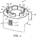
図1〜11に示される実施形態において、本発明の投与量カウンター2は、ふた3、インデクサー4、ユニットティースリング(units teeth ring)5、圧縮バネ6、ユニット回転リング7、10の位の円錐8およびハウジング9を備える。それらの構成部品は、図2、3および7に示されるように組み立てられた。
In the embodiment shown in FIGS. 1 to 11, the
図1は、本発明の投与量カウンター2の分解図を示す。投与量カウンター2は、1の位で単回投与量をカウントするユニットカウンターサブアセンブリを備える。図1に示される実施形態において、ユニットカウンターアセンブリは、10の位の円錐8を除いて、図示される全ての構成部品を備える。本発明の投与量カウンター2の代替実施形態は、本明細書で説明するように、薬剤投与量カウントプロセス中に、10の位の変化をカウントする追加の測定器構成部品を備える(およびいくつかの場合、100の位での変化)。
FIG. 1 shows an exploded view of the
ふた3は、最上部に幅広縁を備える開いた円筒部11を有する。開いた円筒部11は、軸線13と同軸上に配列される軸線を有する。複数(例えば、5つ)の等間隔を置いたスロット14は、縁12を通って延び、およびスロット14の各々は、軸線13に対して同軸上に、環状方法で配置されている湾曲部を有する。各スロット14は、スロット14の湾曲部から放射状に外側へ延びる中央スロット突起部15を有する。図4に示すように、複数(例えば、5つ)のラチェット部材または歯16は、縁12の底面から下方向に突起し、軸線13に対して縁12の周りで周囲方向に等間隔をおいて配置されている。一実施携帯において、本明細書で説明するように、ふた3は外輪18上の台形断面の複数(例えば、5つ)のつまみ17を有し、つまみ17はハウジング9の先端縁上の補助スロットに系合するように形成される。
The
インデクサー4は、軸線13と同軸にあるスプラインリング20に似た形状である。リングは、リングから上向きに突出している複数(例えば、5つ)のスプライン22を有する。スプライン22は、スロット14の湾曲部のように湾曲している。リング20の底部側上には、対の鋸歯状突起部24が各スプライン22の反対側に備えられる。各突起部26の先端部の横断面(軸線13に対して)および各スプライン22は、湾曲スロット14各々および各スロットの中央部15の形状にぴたりと合致するように、突起部26は各スプライン22の先端部に隣接して放射状に外側へ延びる。従って、スプライン22は、スロット14を経て、ふた12へと軸線方向に摺動可能にはめ込むことができる。
The
ユニットティースリング5もさらに、軸線13の同軸にあり、直立歯の2つのリングを備える。歯30の外側リングは、ふた3の縁12の底面上のラチェット部材16と係合するように配置されている。歯32の内側リングは、インデクサー4上の鋸歯状突起部24と係合するように配列されている。ユニットティースリング5は、外側周辺面34内に配置されている軸線方向に配列された複数(例えば、4つ)の溝36を有する外側周辺面36を有する。ユニットティースリング5の軸線13回りにユニットティースリング5を回転させる(例えば、指数付けされた量の各薬剤投与量が投与されるため、リング5が回転する)ためのふた3、インデクサー4およびユニットティースリング5の相互作用は、機能的に、国際公開第2005/060535(A2)号に記載のものと同様である。国際公開第2005/060535(A2)号において、カウント表示は、直立歯の2つのリングを有するカウンターリング外側周辺面を備える。しかし、本件では、ユニットティースリング5自体は表示を有さない。国際公開第2005/060535(A2)号は、参照として本明細書に援用される。
The
ユニット回転リング7は、概して軸線13と同軸の中空円筒38の形である。軸線方向に配列された複数(例えば、4つ)のリブ40は、円筒38の内側面42から放射状に内側へ延びるが、円筒38の底部で形成される斜面リング44において停止する。円筒46の外面46上において、ユニット回転リング7は、円筒38の底面に隣接する辺りに延びる周辺縁48を有する。周辺縁48は、図1に示すように、第1組の欠落した弓形部分またはスロット48a、48b、48c、48dおよび48eを有する(第2組の5つの欠落した弓形部分またはスロット(図示せず)は、第1組とは反対側でユニット回転リング7の周辺に180度で配置されている)。
The
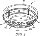
ユニット回転リング7は、その外側周辺面46に、投与される薬剤の1の位での投与量カウントを示す表示を有する。図1に示すように、表示は、円筒38の外面46の周囲に、均等に間隔をあけて配列されている数字9〜0を2回用いてもよい。軸線13に平行な線で下線を引くことができるように数字が配向されており、数字は、ユニット回転リング7の底面から見たとき、時計回りの方向に降順で2回連続配列されている(例えば、9 8 7 6 5 4 3 2 1 0 9 8 7 6 5 4 3 2 1 0の順番)。図5および7に示すように、ユニット回転リング7は、数字0および隣接する数字9の間の各スペースの下および間に間隔をおく楕円形つまみ50を有する。数字9および0はユニット回転リング7の周囲に2回配列されているため、(ユニット回転リング7の反対側に)リング上に2つの楕円状つまみ50がある。
The
ユニット回転リング7上のリブ40は、ユニットティースリング5上の溝36と整列するように配置されている。ユニットティースリング5の外側周辺面34は、円筒38の内側面42より直径がわずかに小さいため、ユニット回転リング7に対してユニットティースリング5の軸線方向運動を可能にする。しかし、そのような軸線方向の運動を可能にするのと同様に、リブ40および各溝36の相互作用は、ユニットティースリング5およびユニット回転リング7を、回転目的のために軸線13に対して連結する。図1に示すように、溝36が配置される外側リング30上で、4つの歯が欠落するが、これは、投与される薬剤の各投与量をカウントする機能には悪影響を及ぼさない。
The
圧縮バネ6は、一実施形態において、環状リーフバネ52の形である。リーフバネ52は、バネ金属の薄板で形成されてよいが、その代りに重合体素材で形成されてもよい。リーフバネ52は、リーフバネ52の外縁56から、放射状に内側へ延びる複数(例えば、4つ)のカットアウト54を有する。カットアウト54の各々がカットアウト内のユニット回転リング7のリブ40の1つを軸線方向に収納するために形成および配列されることにより、ユニット回転リング7に対して圧縮バネ6の軸線方向運動を可能にする。リーフバネ52は、複数(例えば、4つ)の軸線方向に延びるバネ要素またはその上のリーフ60を備える環状リング58を有する。バネ要素60は、ユニット回転リング7の円筒38内の斜面リング44の先端部とかみ合わせるために、リング58から下向きにバイアスされる。一実施形態において、各リーフ60の外端は曲げられ、または斜面リング44に対して外端の滑らかな滑りを容易にするために形成される。リーフバネ52のリング58の上面は、ユニットティースリング5の底面と係合する。従って、リーフバネ52は、ユニットティースリング5が軸線方向にユニット回転リング7の斜面リング44から離れるように、ならびにインデクサー4上の鋸歯状突起部24およびふた3の縁12の底面上のラチェット部材16に向かうように促進する。あるいは、リーフバネの反対側が、斜面リング44の先端部をかみ合わせるのと同様に、バネ要素60がユニットティースリング5の底面とかみ合わせるために、リング58から上向きにバイアスされるように、リーフバネ52は、反対側を上にして取り付けられてもよい。別のアセンブリは、本発明他の実施形態にさらに応用してもよい。
The
図示されるリブ40および溝36と同様に、ユニットティースリング5およびユニット回転リング7間の任意の好適に適合させた機構は、回転のためにそれらの2つの構成部品を連結するには十分であり、さらに相対的軸線方向運動を可能にする。一実施形態において(図示せず)、ユニットティースリング5またはユニット回転リング7に対して圧縮バネ6の回転が可能となる。しかし、ユニットティースリング5またはユニット回転リング7に対する圧縮バネ6の回転はさらに制限されることが可能な限り所望され、リブ40およびカットアウト54が上記の目的のために図示されるのと同様に、任意の好適に適合させた機構が目的を達成するのに十分である。
As with the illustrated
ハウジング9は、円筒体62から外側へ突出した2つの前翼64および円筒体から下方に延びる2本の前脚66を備える円筒体62を概して有する(1本のみを図1に示す)。円筒体62および翼64および脚66は、エアゾール容器70用のアクチュエータハウジング68の内部表面と結合するように形成されている(図3参照)。視認ウィンドウ72は、円筒体62を備える。円筒体62の内側周辺面74上において、突起部76は、図3に示すように、ユニット回転リング7と一直線に配置される。円筒体62は、ハウジング9とふた3のスナップ式接続を提供するために、複数(例えば、5つ)のふた3上の突起部17の収納用に形成されたスロット78を備える先端縁を有し、または構成部品は圧入されてよく、超音波または別の方法(例えば、レーザ)で溶接されてもよい。
The
ハウジング9は、図3および6で明らかなように、10の位の円錐8を凹所内に収容するために設計された下位後部内側円錐状凹所80を有する。従って、10の位の円錐8は、安定した方法で、凹所80の後部隅部82から前方および上方に斜めに向けられた軸線回りに回転することが可能である。一代替実施形態において(図示せず)、10の単位の円錐8は、ハウジング9から部分的に突出し、エアゾール容器を収納するアクチュエータハウジングの内部から前方および上方に斜めに向けられた軸線回りの回転を支持する一部である。
The
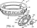
10の位の円錐8は、尖った端86から見たとき、10の位の円錐8の外側錐面84の回りに降順時計回りに配列されている12〜0の番号を有する。番号の方向は、錐面84の先端から斜めの線で下線を引くことができる(例えば、12 11 10 9 8 7 6 5 4 3 2 1 0の順)。10の位の円錐8の内側面87は、図7に示すように、錐面84から反対方向を指す隆起錐台88を有する。さらに、10の位の円錐8の内側面87上において、等間隔をおいたペグ90の環状連続は、錐台88(図8に示すように、10の位の円錐8の軸線92に平行)と同じ方向に平行に延びる。図7にさらに示すように、ふた3の円筒部11は、ホコリ、繊維、綿毛またはその他の破片の侵入を防ぐために、ハウジング9の円錐状凹所80の先端を覆うように延びる下位弓状棚11aを有する。
The
投与量カウンター2は、ハウジング9の凹所80の後部隅部82内に位置する10の位の円錐8の錐面84の尖った端86を備えるハウジング9に10の位の円錐8を挿入することによって組み立てられてもよい。リング7および円錐8の正しい方向により、周辺縁48を交差する3つのペグ90を備えるユニット回転リング7がハウジング9の突起部76上に配置されるように、ユニット回転リング7の周辺縁48は、10の位の円錐8上の3つのペグ90の位置に対応する3つのスロット48c、48dおよび48eを縁内に有する。バネ6、ユニットティースリング5およびインデクサー4は、順にユニット回転リング7を覆って組み立てられ、ふた3はインデクサー4のスプライン22を適合し、それからハウジング9と係合される。従って、図2に示すように、この全てのアセンブリが投与量カウンター2を特徴づける。組み立てられた時点で、投与量カウンター2の内側動作構成部品は、ハウジング9およびふた3によって非常によく取り囲まれているため、それらの動作構成部品を保護するためにホコリ、繊維、綿毛またはその他の破片の侵入を防ぐ。投与量カウンター2の動作構成部品の筺体(ハウジング9と係合されたふた3を備える)は、ある程度の耐タンパー性、耐久性、耐衝撃性のあるアセンブリを提供する。
The
図3は、図1および2の投与量カウンター2を組み入れる「押して吸う」エアゾール吸入器の一部の縦断面図を示す。投与量カウンターの目的は、薬剤の残量投与回数または(一代替実施形態において、図示せず)投与済みの回数を示す表示部を提供することである。利用者による確認のための表示は、投与された投与量の順次的な数え上げまたは逆数え、もしくは「満タン」または「空」などのより一般的な表記の提供をする好適なアルファベット、数字、英数字またはカラーシンボル、またはそれらの任意の組み合わせであってもよい。表示は、アクチュエータハウジング68の側壁96のウィンドウ94を通して確認できる。あるいは、側壁96は、視認領域もしくは、表示ならびにカウントを見るレンズを提供するために透明であってよく、または少なくとも透明な素材でできた部分を有してもよい。「押して吸う」吸入器は、エアゾール容器70を収容するために円筒体98を有するアクチュエータハウジング68を備える。アクチュエータハウジング68は、マウスピース100を有する。ノズルブロック102は、アクチュエータハウジング68内に位置し、エアゾール容器70のバルブステム104および投与量開口部106を収容するために口径を有する。エアゾール容器70の計量バルブ108は、バルブ口金110、バルブステム104、計量チャンバ112および伸縮バネ114を有する。図3に示すように、エアゾール容器70は、軸線13と同軸上にさらに配列される。
FIG. 3 shows a longitudinal cross-sectional view of a portion of a “push-and-suck” aerosol inhaler that incorporates the
ハウジング9は、アクチュエータハウジング68内の薬剤投与量および気流路の障害および障害物を最小限に抑えるように設計されている。一実施形態において、投与量カウンター2は、アクチュエータハウジング68および投与量カウンター2の間において、好適な戻り止めまたはその他の係合構造(図示せず)によりアクチュエータハウジング68内に留められる、または保持される。さらに、投与量カウンター2は、様々な計量バルブ構造との使用に適するように、および市販のアクチュエータハウジング側面に密に適合するように設計されており、そのため、ハウジング内に本発明の投与量カウンター2を収容するためにそれらのアクチュエータハウジングの外部構成を変更する必要がない。図は、加圧エアゾール容器(加圧定量投与吸入器すなわちPMDI)による薬剤投与に使用される種類の吸入器用アクチュエータハウジングとの組み合わせで、本発明の投与量カウンター2を示す。しかし、他の構造の吸入器は、例えば、ドライパウダー吸入器、携帯用ネブライザ、および相互作用を利用するその他の定量投与ディスペンサを含む本発明品とともに使用してもよい。
The
吸入器は、アクチュエータハウジング68に対してエアゾール容器70を下に押すことによって、薬剤の投与量が投与されるように作動される。吸入器が作動されたとき、エアゾール容器70の下方運動は、バルブ口金110をインデクサー4のスプライン22の上面22aと係合させる。ふた3はバルブ口金110に対して十分に低く位置されているため、それらの構成部品は互いに係合されず、従って、薬剤投与量の投与が保証されるように適切な計量バルブの移動を可能にするために十分な間隔を確保する。バルブ口金100との係合は、インデクサー4をふた3に対して下方へ動かして、インデクサー4の鋸歯状突起部24をユニットティースリング5の歯32の内側リングの歯と係合させる。ふた3上のラチェット部材16を取り除くために、歯30の外側リングが十分に低く動いた時点で、リング5は回転する(国際公開第2005/060535(A2)号に記載)。そのような回転運動は、ユニット回転リング7の回転運動の係合をもたらす。ユニット回転リング7およびユニットティースリング5の間の圧縮バネ6は、エアゾール容器70の下方への作動力が排除されるまで、鋸歯状突起部24および歯32の内側リングとの係合を維持し、伸縮バネ114は、インデクサー4からバルブ口金110を分離する。これは圧縮バネ6がインデクサー4を上方に戻すことを可能にし、ユニットティースリング5上の歯30の外側リングのふた3上のラチェット部材16との相互作用は、ユニット回転リング7の回転運動とさらに係合したユニットティースリング5のさらなる回転運動をもたらすことにより、1の位のカウントの変化を完了、作動への対応および薬剤の単回投与量への対応をする。投与量カウンター2は、エアゾール容器70の計量バルブ108の投与量時点(または直前)で計数するように設計されており、それに続く任意の過度の軸運動を「失う」(例えば、投与量カウンター2の軸線方向へ動作する構成部品の失われた「運動」)。従って、吸入器の各作動のために、ユニット回転リング7は、1測定増加分を回転で動かすように指数付けされ、これがウィンドウ72および94を通して目で確認できる1の位のカウントを変える。
The inhaler is actuated so that a dose of drug is dispensed by pushing the
ウィンドウ72および94を経て表示される10の位を変えるために、ウィンドウ72を過ぎた錐面84の番号軸線受部を動かすよう、ユニット回転リング7の回転の機能として10の位の円錐8が回転する。図8に示すように、ユニット回転リング7および10の位の円錐8の軸線13および92は、互いに対して鈍角αを成して配置される(例えば、互いに対して90度より大きく180度未満の角度を成して配置される)。一実施形態において、角度αは110度〜160度の範囲にある。一代替実施形態において、角度αは125度〜145度の範囲にある。さらに別の実施形態において、角度αは135度である。一実施形態において、軸線13および92は、互いに対して同一平面上にあるが、同軸、平行または垂直ではない。
As a function of the rotation of the
図3および7に示すように、10の位の円錐8およびユニット回転リング7の部分は、ハウジング9の視認ウィンドウ72に隣接して集中する。視認ウィンドウ72において、1の位の表示を有するユニット回転リング7の外面46の周辺部分および10の位の表示を有する錐面84の弓形部分は、薬剤量カウントの少なくとも一部分をまとめて示すために配列される(例えば、図2において、カウント「120」が示され、図9において、カウント「129」が示される)。ユニット回転リング7および10の位の円錐8の表示体支持面の並置において、それらの表面は、2つの個々の表示体支持面において表示を見るために共通視認領域を提供する視認ウィンドウ72において互いに接している。上記のように、投与量カウンター2がアクチュエータハウジング68内に配置されたとき(図3参照)、視認ウィンドウ72は、アクチュエータハウジング68の側壁96において視認ウィンドウ94と配列されるため、利用者による観測のための共通視認領域を提示する。一実施形態において、共通視認領域は、軸線13の周りに配置された円筒の周辺面に概ね接している(図8参照)。
As shown in FIGS. 3 and 7, the
ユニット回転リング7の毎10運動は、楕円状つまみ50(ユニット回転リング7上)の1つおよびペグ90(10の位の円錐8上)の1つの相互作用により10の位の円錐8の運動をもたらす。つまみ50およびペグ90の関係は、図10A〜10Dおよび図11A〜11Dに模式的に示される。このユニット回転リング7と10の位の円錐8との直接相互作用は、任意の転換ギヤの必要性ならびに1の位の表示を有する構成部品(例えば、ユニット回転リング7)と10の位の表示を有する構成部品(例えば、10の位の円錐8)とのその他の運動転換構成部品の必要性を排除する。この配置は、より少ない部品しか要さず、機能上より経済的、および小型である。さらに、投与量カウンターにおけるより少ない構成部品の使用は、特定の許容範囲内で製造されなければならない構成部品の数を減少し、従って、許容値堆積による構成部品の不適合または作動不能の可能性を減少する。
Every ten movements of the
10の位の円錐8がウィンドウ72において表示を変化させるための順序通りの相互作用は、ユニット回転リング7上のつまみ50の1つと10の位の円錐8上のペグ90の1つとの係合を伴う。図10Aに示すように、ユニット回転リング7が時計回りに回転すると、その上のつまみ50の1つは、結果的に10の位の円錐8上のペグ90aとの係合に移る。図11Aは、10の位の円錐8に関連してユニット回転リング7の回転によりもたらされる最初の係合時のつまみ50およびペグ90aの関係を示す。図10Bに示すように、ユニット回転リング7が時計回りの回転を続けると、図10Bに見られるように、つまみ50はペグ90aを左に押し、それにより、図11Bにさらに示すように、反時計回り方法で10の位の円錐8を軸線回りに回転させる。図10Cに示すように、ユニット回転リング7の継続する時計回りの回転は、つまみ50がペグ90aを左にさらに押す要因となり(図10Cおよび11Cに示す)、それにより、10の位の円錐8を反時計回り方法で軸線回りにさらに回転させる。結果的に、図10Dおよび11Dに示すように、つまみ50はペグ90aを押すことにより、10の位の円錐8の回転は、前進するつまみ50の経路からペグ90aを移動させる(例えば、図11Dに示すつまみ50の下方)。この動作が起こる時点で、さらに10の位の円錐8の反時計回りの回転運動は停止し、新しい10の位の番号が視認ウィンドウ72を通して見られるように配列される。投与量残量の数のカウントダウンを示すために10の位の番号が回転する一実施形態において、表示された新しい10の位の番号は、表示されていた前回の番号よりも小さい。
The in-order interaction for the
ユニット回転リング7の回転に対して10の位の円錐8の回転は、つまみ50の1つがペグ90の1つと係合する度に生じる。一実施形態において、ユニット回転リング7上に2つのつまみがあり、ユニット回転リング7の完全な各回転(20の1の位の番号を示す)のために10の位の円錐8は2つの10の位の番号を通過して回転する。一代替実施形態において、ユニット回転リング7の回転の機能としての10の単位の円錐8の回転は、ユニット回転リング7上により多くのまたは少ないつまみ50を備えることにより、より多い頻繁または少ない頻度にすることができる。図示する実施形態において、10の位の円錐8の錐面84は弓形部分を有する13の10の位の番号を有し、内側面87上の10の位の円錐8は対応する13のペグ90を有する。より多くのまたは少ない番号部分が10の位の円錐8上に備えられることが所望される場合、ペグ90の数も、それ故、同様の方法で適宜に調整されるべきである。
The rotation of the
図10および11において、10の位の円錐8のペグは、90a、90b、90c等とする。上記のように、ユニット回転リング7の外面46は、図10および11の連続図に示すように、その上にペグ90の運動を可能にするために各つまみ50に隣接して配列されたロット48aおよび48bを有する周辺縁48を有する。従って、ペグ90aはつまみ50によって動かされるため、ペグ90cは周辺リング48内のスロット48bを通過して動く(図11Aに示すスロット48bの下方から図11Dに示すスロット48bの上方に向けて)。同様に、10の位の円錐8が回転すると、ペグ90mはスロット48aを通過して動く(図11Aに示す周辺縁48から図11Dに示す周辺縁48に向けて)。
10 and 11, the pegs of the
つまみ50の1つがペグ90の1つと係合するとき以外は、周辺縁48は10の位の円錐8の回転を防ぐために作動する。例えば、図11Aに示すように、10の位の円錐8は、ペグ90mおよび90l間で延びる周辺縁48により軸線回りに運動を制限される。図10Bおよび10Cに示すように、ユニット回転リング7および10の位の円錐8が配列されるとき、10の位の円錐8の運動が可能になると同時に、図11Dに示す構造において10の位の円錐8は、ここでもまた直ちに運動を止められる。図11Dに示す位置において、周辺縁48はペグ90aおよび90d間で延び、ユニット回転リング7の回転に伴い周辺縁48は隣接するペグ90aおよび90m間および隣接するペグ90cおよび90d間で延びる。従って、1の位の数字の表示のために、ユニット回転リング7が軸線13の回りで回転しているにも拘わらず、10の位の円錐8がユニット回転リング7上のつまみ50の1つとの相互作用によって動かされた時点で、円錐は10の位の円錐8上のペグ90bとの係合により別のつまみ50が現れるまで回転できない。一実施形態において、共同機構は、ハウジング9および10の位の円錐8間に備えられ、10の位の円錐8が視認ウィンドウ72に10の位の「0」の数字を示す位置まで回転したとき、10の位の円錐8のさらなる回転を防ぐ。ユニット回転リング7は、1の位の残りの9つのカウントを逆に数えるように回転し続けることが可能で、その後10の位の円錐8によってさらなる回転を止められる。この時点で投与量カウンター2の視認ウィンドウは、ゼロカウントを表示する。さらなる薬剤がエアゾール容器にある限り、利用者によってエアゾール投与アセンブリを使用して投与され得るが、投与量カウンター2はそれ以上の投与量カウントを記録しない。別の手段として、エアゾール投与アセンブリは、例えば、インデクサー4の自由運動を制限することにより、ゼロカウントに達した時点で投与量投与を停止する設計にすることが可能である。
Except when one of the
本質において、図1〜11の実施形態に示す本発明の投与量カウンターは、以下の方法で機能する。利用者が、エアゾール容器70をアクチュエータハウジング68へと下方に押すことにより吸入器を作動させるとき、バルブ口金110は下方に押すためにインデクサー4と係合する。インデクサー4は係合し、次にユニットティースリングを回転させる。ユニット回転リング7がユニットティースリング5に回転連結するため、ユニットティースリング5も同様に回転する。エアゾール容器70がその中の薬剤の単回投与量を完了するために上下往復動をするため、インデクサー4およびユニットティースリング5は、ユニット回転リング7に対してさらに上下往復動をする。ユニットティースリング5の1度の完全な上下往復動は、ユニット回転リング7の1の位の単回カウント変化の位置である軸線13上でユニット回転リング7を回転させる。ユニット回転リング7の回転は、ユニット回転リング7上のつまみ50と10の位の円錐8上のペグ90の1つとの係合により10の位の円錐8の回転につながる。しかし、10の位の円錐8は、カウントの10の単位の変化を示すために、ユニット回転リング7に対して周期的にのみ回転する(例えば、10の位の円錐8はユニット回転リング7の動き10回に対して1回の割合でのみ動く)。ユニット回転リング7が1の位のカウントを10回数える度に、10の位の円錐8は、それについて表示される10の位のカウントを変えるために、1つ位置をずらして指数付けされる。
In essence, the dose counter of the present invention shown in the embodiment of FIGS. 1-11 functions in the following manner. When the user activates the inhaler by pushing the
図示の実施形態において、最大限の投与量カウントである「129」の薬剤投与量が示される。これは、120回の利用者可能投与カウント残量で、いくつかのエアゾール投与アセンブリの実験(例えば、9回の初期カウント可能)を可能にする。上記するように、ユニット回転リング、および/または10の位の円錐上の表示の頻度または間隔を変更することは(それらの構成部品間の相互配列において対応する変更を伴う)、図示する可能カウント表示の修正を可能にする。 In the illustrated embodiment, a maximum dosage count of “129” is shown. This allows experimentation of several aerosol dosing assemblies (eg, 9 initial counts possible) with 120 user available dosing count balances. As indicated above, changing the frequency or spacing of the display on the unit rotation ring and / or the tens cone (with a corresponding change in the mutual alignment between those components) is possible illustrated Allows modification of the display.
投与量カウント表示の変更の理由の1つは、吸入器の2つの作動を要する製品用の単回に処方された投与量である。システムにおいて、240の作動をカウントする可能性は、以下の修正により実現できる。ユニット回転リングは、楕円状つまみ50を1つ(2つではない)のみ、および同様に周辺縁48内にスロット48aおよび48bを1組(2組ではない)のみを有する。ユニット回転リング7の表示は、その周囲において以下の順に配置される。上述の表示パターン9 8 7 6 5 4 3 3 2 1 0の代わりにむしろ、9*8*7*6*5*4*3*2*1*0*(またはアスタリスクの代わりに「1/2」)。次に、10の位の円錐8は、そこで10の作動毎後よりむしろ、ユニット回転リング7の20作動毎後(10回の投与量)に動く。これは、本発明の投与量カウンターが120回に制限されるよりむしろ、240回の作動事象を実現することを可能にする。
One reason for changing the dose count display is a single prescribed dose for products that require two actuations of the inhaler. The possibility of counting 240 operations in the system can be realized with the following modifications. The unit rotation ring has only one (not two)
図1〜11に示す本発明の投与量カウンターの実施形態は、1の位および10の位の表示の変化を可能にする一方、100の位の表示の変化は可能ではない。図12〜20は、0〜299までの可能投与量カウントを利用者に提供する本発明の投与量カウンターを示す。投与量カウンター202は、図1〜11の投与量カウンター2と同様だが、修正された10の位の円錐208、ハウジング209および100の位の円盤225を含む。投与量カウンター202の他の構成部品は、本質的に、投与量カウンター2のために説明したものと同様である。例えば、ふた3、インデクサー4、ユニットティースリング5、圧縮バネ6およびユニット回転リング7は、本質的に同様であり、上述したものと同様に機能する。ユニットティースリング5を軸線13回りに回転させる(例えば、リング5が回転すると、指数付けされた量の各薬剤投与量が投与される)ためのふた3、インデクサー4およびユニットティースリング5の相互作用は、機能的に、国際公開第2005/060535(A2)号に記載のものと同様である。ユニット回転リング7と10の位の円錐208との相互作用は、ユニット回転リング7の回転の機能として10の位の円錐208をその軸線回りに回転させるということと、また同様である。
While the embodiment of the dose counter of the present invention shown in FIGS. 1-11 allows a change of the 1's and 10's displays, a change of the 100's display is not possible. Figures 12-20 show the dose counter of the present invention that provides the user with a possible dose count from 0 to 299.
本実施形態において、円錐の尖った端286から見たとき、10の位の円錐208は、10の位の円錐208の外側錐面284の周りに降順時計回りに配列されている9〜0の番号を有する(例えば、9 8 7 6 5 4 3 2 1 0の順)。番号の読み取り方向は、10の位の円錐8上の方向と同様である。10の位の円錐208上において、錐面284は尖った端286までは延びない。10の位の円錐面284は、10の位の円錐208の外周辺縁に隣接するバンド内のみで延びる。環状凹所284aは、バンド内に集中的に配置され、小型の円錐284bは、尖った端286で覆われている凹所284a内で集中的に突出する。さらに、円錐284bを囲む周辺縁285は、凹所284a内で突出する。縁285は、縁内に単独のギャップ285aを有し、凹所284aは、一般的にギャップ285aから放射状におよび外側に延びる、凹所から突出するランプ289をさらに有する。10の位の円錐208の内側面287は、図18に示すように、錐面284から反対方向を指す隆起錐台288を有する。さらに、10の位の円錐208の内側面287上において、等間隔をおいたペグ290の環状連続は、錐台288(図19に示すように、10の位の円錐208の軸線292に一般的に平行)と同じ方向に平行に延びる。10の位の円錐208の外側面284上には10の番号しかないため、内側面287上には対応する10のペグ290しかない。
In this embodiment, when viewed from the
この場合にもハウジング209は、一般的に、円筒体から外側へ突出した2つの前翼264および円筒体から下方に延びる2本の前脚266を備える円筒体62を有する。円筒体262および翼264および脚266は、エアゾール容器70用のアクチュエータハウジング68の内部表面と結合するように形成される。カウント視認ウィンドウ272は、円筒体内に備えられる。円筒体262の内側周辺面274上において、突起部276は、図16に示すように、ユニット回転リング7と一直線に配置される。円筒体262は、ハウジング209のふた3スナップ式接続を提供するために、複数(例えば、5つ)のふた3上の突起部17の収納用に形成されたスロット278を備える先端縁を有し、または構成部品は圧入されてよく、超音波または別の方法(例えば、レーザ)で溶接されてもよい。
Again, the
ハウジング209は、図16および18で明らかなように、10の位の円錐208を凹所内に収容するために設計された下位後部内側円錐状凹所280を有する。従って、10の位の円錐208は、安定した方法で、凹所280の後部隅部282から前方および上方に斜めに向けられた軸線回りに回転することが可能である。ハウジング209は、一般的に、収納および100の位の円盤225の部分的回転支持のために、凹所280に隣接する垂直に配列された弓形スロット279をさらに有する。100の位の円盤225は、一般的に、回転軸線229に垂直に延びる外側表示体支持面227を有する(例えば、図19参照)。外側面227は、その上に降順時計回りに配列されている2〜0の番号を有する。番号の方向は、概ね隣接し、軸線229から外側へ延びる放射状の線により水平に2等分される各番号を備える円状外側面227の周辺縁に接している。100の位の円盤225の内側面231は、軸線229に概ね平行の方向で円盤から外側へ突出した3つの環状に等間隔をおいたペグ233を有する(図17参照)。多いカウントは、より大きい100の位の円盤上のより多くの番号および適合するより多くのペグを組み込むことにより可能になる。組み立て時、100の位の円盤225の内側面231は、10の位の円錐208の外側面284の突起部部分に面し、係合する。
The
投与量カウンター202は、ハウジング209のスロット279へ100の位の円盤225を挿入することによって組み立てられてもよい。10の位の円錐208は、ハウジング209内の凹所280の後部隅部282内に位置するハウジング上の小型の円錐284bの尖った端286を備えるハウジング209に挿入される。表示カウント態様において、100の位の円盤225の100の位の番号「2」は視認ウィンドウ272を通して観測のために「0」が配列され、10の位の円錐208の10の位の番号は視認ウィンドウ272を通して観測のために配列される。リング7および円錐208の正しい方向により、周辺縁48を交差する3つのペグ290を備えるユニット回転リング7がハウジング209の突起部276上に配置されるように、ユニット回転リングの周辺縁48は、10の位の円錐208上の3つのペグ290の位置に対応する3つのスロット48c、48dおよび48e(図1に示す)を縁内に有する。始めに組み立てられた時点で、ユニット回転リング7上の1の位の番号「9」は、視認ウィンドウ272を通して観測のために配列される。バネ6、ユニットティースリング5およびインデクサー4は、順にユニット回転リング7を覆って組み立てられ、ふた3はインデクサー4のスプライン22を適合し、それからハウジング209に係合される。従って、図15に示すように、この全てのアセンブリが投与量カウンター202を特徴づける。組み立てられた時点で、投与量カウンター202の内側動作構成部品は、ハウジング9およびふた3によって非常によく取り囲まれているため、それらの動作構成部品を保護するためにホコリ、繊維、綿毛またはその他の破片の侵入を防ぐ。投与量カウンター202の動作構成部品の筺体(ハウジング9に係合されたふた3を備える)は、ある程度の耐タンパー性、耐久性、耐衝撃性のあるアセンブリを提供する。
The
図示する第2の実施形態において、最大限の投与量カウントである「299」薬剤投与量が示される。これは、利用者が使える200回の残り投与カウントで、いくつかのエアゾール投与アセンブリの実験(例えば、利用可能な9回の初期「テスター」カウント)を可能にする。ユニット回転リング、10の位の円錐および/または100の位の円盤上の表示の頻度または間隔を変更することは(それらの構成部品間の相互配列において対応する変更を伴う)、図示する可能カウント表示の修正を可能にする。 In the second embodiment shown, a maximum dose count of “299” drug dose is shown. This allows several aerosol dosing assembly experiments (eg, 9 available initial “tester” counts) with 200 remaining dose counts available to the user. Changing the frequency or spacing of the display on the unit rotation ring, the tens cone and / or the tens disk (with corresponding changes in mutual alignment between their components) is possible illustrated Allows modification of the display.
図16は、図12、15および18の投与量カウンター202を組み入れる「押して吸う」エアゾール吸入器の一部の縦断面図を示す。上記のように、投与量カウンターの目的は、薬剤の残量投与回数または(一代替実施形態において、図示せず)投与済みの回数を示す表示部を提供することである。利用者による確認のための表示は、投与された投与量の順次的な数え上げまたは逆数え、もしくは「満タン」または「空」などのより一般的な表記の提供をする好適なアルファベット、数字、英数字またはカラーシンボル、またはそれらの任意の組み合わせであってもよい。表示は、アクチュエータハウジング68の側壁96のウィンドウ94を通して確認できる。あるいは、側壁96は、視認領域もしくは、表示ならびにカウントを見るレンズを提供するために透明であってよく、または少なくとも透明な素材でできた部分を有してもよい。「押して吸う」吸入器は、図3に示す構造および構成部品と同様であり、さらに1の位の単回投与量カウントを起動し、同じくユニット回転リング7と10の位の円錐208の協働によりカウントのために10ごとに変化(即ち、10の位)するのと同じ方法で、投与量カウンター202と協働する。図6に示すように、エアゾール容器70は、軸線13と同軸上に配列される。
FIG. 16 shows a longitudinal cross-sectional view of a portion of a “push inhale” aerosol inhaler that incorporates the
ハウジング9は、アクチュエータハウジング68内の薬剤投与量および気流路の障害および障害物を最小限に抑えるように設計されている一実施形態において、投与量カウンター202は、アクチュエータハウジング68および投与量カウンター202の間において、好適な戻り止めまたはその他の係合構造(図示せず)によりアクチュエータハウジング68内に留められる、または保持される。さらに、投与量カウンター202は、様々な計量バルブ設計との使用に適するように、および市販のアクチュエータハウジングのプロファイルに密に嵌るように設計されており、そのため、ハウジング内に本発明の投与量カウンター202を収容するためにそれらのアクチュエータハウジングの外部構成を変更する必要がない。図は、加圧エアゾール容器による薬剤投与に使用される種類の吸入器用アクチュエータハウジングとの組み合わせで、本発明の投与量カウンター202を示す。しかし、他の構造の吸入器は、例えば、ドライパウダー吸入器、携帯用ネブライザ、および相互作用を利用するその他の投与量ディスペンサを含む本発明品とともに使用してもよい。
In one embodiment, the
図14、16、18および19に示すように、100の位の円盤225、10の位の円錐208およびユニット回転リング7の部分は、ハウジング209の視認ウィンドウ272に隣接して集中する。視認ウィンドウ272において、1の位の表示を有するユニット回転リング7の外面46の周辺部分、10の位の円錐208の錐面284の弓形部分および100の位の円盤225の外側面227の弓形部分は、薬剤量カウントをまとめて示すために配列される(例えば、図14において、カウント「100」が示され、図15において、カウント「098」が示される)。ユニット回転リング7の表示体支持面の並置において、10の位の円錐208および100の位の円盤225の表面は、3つの個々の表示体支持面において表示を見るために共通視認領域を提供する視認ウィンドウ272において互いに連続的に接している。従って、100の位の円盤の外側面272は、視認領域272に概ね平行である。上記のように、投与量カウンター202がアクチュエータハウジング68内に配置されるとき(図16参照)、視認ウィンドウ272は、アクチュエータハウジング68の側壁において視認ウィンドウ94と配列されるため、利用者による観測のための共通視認領域を提示する。共通視認領域は、軸線13の周りに配置された円筒の周辺面に概ね接している。
As shown in FIGS. 14, 16, 18, and 19, the
図19に示すように、100の位の円盤225の回転軸線229およびユニット回転リング7の回転軸線は互いに垂直である。100の位の円盤225の軸線229は、10の位の円錐208の軸線92に対して鈍角βを成して配置されている。角度βは、上記のように角度αに関しての範囲または値と同様と想定され得る。一実施形態において、軸線13および292は同一平面上にあるが、互いに対して同軸、平行または垂直ではない。同様に、一実施形態において、軸線292および229は同一平面上にあるが、互いに対して同軸、平行または垂直ではない。本発明の別の実施形態においては、これらの軸線の対は同一平面上にある必要はない。
As shown in FIG. 19, the
ユニット回転リング7の毎10運動は、楕円状つまみ50(ユニット回転リング7上)の1つおよびペグ290(10の位の円錐208上)の1つの相互作用により10の位の円錐208の運動をもたらす。従って、10の位の円錐208は、軸線13回りにユニット回転リング7の回転の機能として軸線292回りに回転する。10の位の円錐208上のペグ290の数は第1の実施形態のものとは異なるが、10の位の円錐208とユニット回転リング7との相互作用の過程は、図10および11に示すように同様である。ユニット回転リング7のつまみ50は、ユニット回転リング7の回転に応じて10の位の円錐208を回転させるために、10の位の円錐208の各ペグ290と順次に係合する。ユニット回転リング7上の周辺リング48は、リング内のスロット48aおよび48b(つまみ50と相対的に配置されている)との協働により、ユニット回転リング7の継続する回転を可能にする一方、必要に応じて10の位の円錐208の回転を可能にするが、ある時には回転を抑制する。
Every 10 movements of the
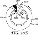
10の位の円錐208の完全な各回転は、(10の位の円錐208上の)ランプ289と(100の位の円盤225上の)ペグ233の1つとの相互作用により、100の位の円盤225の回転運動をもたらす。ランプ289およびペグ233の関係は、図20A〜20Fに模式的に示されている。この10の位の円錐208と100の位の円盤225との直接相互作用は、任意の転換ギヤの必要性ならびに10の位を有する構成部品(例えば、10の位の円錐208)と100の位を有する構成部品(例えば、100の位の円盤225)とのその他の転換構成部品の必要性を排除する。この配置は、より少ない部品しか要さず、機能上より経済的で小型である。
Each complete rotation of the
100の位の円盤225がウィンドウ272において表示を変化させるための相互作用および順序は、10の位の円錐208上のランプ289の1つと100の位の円盤225上のペグ233の1つとの係合を伴う。図20Aに示すように、10の位の円錐208は、反時計回りに回転し、ランプ289は結果的に100の位の円盤225上のペグ233aとの係合に移る。図20Bに示すように、10の位の円錐208が反時計回りの回転を続けると、図10Bに示すように、ランプ289はペグ233aを押し(図20Bに示すように、下方および左に)、それにより、100の位の円盤225を反時計回り方法で軸線回りに回転させる。図20Cに示すように、ユニット回転リング7のさらなる反時計回りの回転は、ランプ289がペグ233aを下におよび左にさらに押す要因となり、それにより、100の位の円盤225を反時計回り方法で軸線回りにさらに回転させる。図10Dに示すように、10の位の円錐208のさらなる反時計回りの回転は、ランプ289がペグ233aを下におよび左にさらに押す要因となり、それにより、100の位の円盤225を反時計回り方法で軸線回りにさらに回転させる。結果的に、図20Eに示すように、ランプ289はペグ233aをかなり下に押すことにより、100の位の円盤225の回転は、前進するランプ289の弓状経路からペグ233aを移動させる(即ち、図20Eに示すように、ランプ289が届かない)。この動作が起こる時点で、さらに100の位の円盤225の反時計回りの回転運動は停止し、新しい100の位の番号が視認ウィンドウ272を通して見られるように配列される。残余投与回数のカウントダウンを示すために100の位の番号が回転する一実施形態において、表示された新しい100の位の番号は、表示されていた前回の番号よりも小さい。
The interaction and order for the
10の位の円錐208の回転に対して100の位の円盤225の回転は、ランプ289がペグ233の1つと係合する度に生じる。一実施形態において、単独のランプ289があり、10の位の円錐208の各単回回転のために、100の位の円盤225は1つの10の位の番号を通過して回転する(または、100の位の円盤225は3つの100の位を有し、100の位の円盤225が120回転すること)。
The rotation of the
図20A〜20Fにおいて、100の位の円盤225のペグはペグ233a、233bおよび233cとして参照する。上記のように、10の位の円錐208の外側面284は、その上に環状凹所284aを有する。凹所284aはペグ233を収容するために形成される。周辺縁285は、隣接したランプ289と配列されたスロット285aを有し、図20A〜20Fの連続図に示すように、ペグ233の運動を防ぐために備えられている。従って、ペグ233aがランプ289によって動かされると、ペグ233cは、周辺縁285内のスロット285aを通過して動く(図20Aに示すスロット285aの下方から図20Dに示すスロット285aの上方に向けて)。同時に、ペグ233aはスロット285aの上方から(図20A参照)スロット285aの下方まで動く(図20E参照)。
20A-20F, the pegs of the
ランプ289がペグ233の1つと係合するとき以外は、周辺縁285は100の位の円盤225の回転を防ぐために作動する。例えば、図20Fに示すように、100の位の円盤225は、ペグ233cおよび233a(およびペグ233b)間で延びる周辺縁285により軸線回りの運動が制限される。図20A〜20Eに示すように、10の位の円錐208および100の位の円盤225が配列されるとき、100の位の円盤225の運動が可能になると同時に、図20Fに示す構造において100の位の円盤225は、ここでもまた直ちに運動を止められる。周辺縁285は向かい合ったペグ233cおよび233a(またはペグ233cおよび233b)間で延び、10の位の円錐208の継続する回転はこの関係を、周辺縁285のスロット285aが図20Aに示す位置に達するまで維持される。従って、10の位の数字の表示のために、10の位の円錐208が軸線回りに回転しているにも拘わらず、100の位の円盤225が10の位の円錐208上のランプ289との相互作用によって動かされた時点で、円盤は100の位の円盤225上のペグ233cとの係合によりここでまたランプ289が現れるまで回転できない。
Except when the
一実施形態において、協働機構は、ハウジング9および100の位の円盤223間に備えられ、100の位の円盤225が視認ウィンドウ272に100の位の「0」の数字を示す位置まで回転したとき、100の位の円盤225のさらなる回転を防止する。10の位の円錐208は、10の位の残りの10のカウントをカウントダウンするときに回転し続けることが可能で、100の位の円盤225によるさらなる回転が防止される。この時点でユニット回転リング7は、1の位の残りの9カウントをカウントダウンするように回転し続けることが可能で、10の位の円錐208によるさらなる回転が防止される。この時点で投与量カウンター202の視認ウィンドウは、ゼロカウントを表示する。さらなる薬剤がエアゾール容器にある限り、利用者によってエアゾール投与アセンブリを使用して投与され得るが、投与量カウンター202はそれ以上の投与量カウントを記録しない。別の手段として、エアゾール投与アセンブリは、例えば、インデクサー4の自由運動を制限することにより、ゼロカウントに達した時点で投与量投与を停止するように設計することが可能である。
In one embodiment, a cooperating mechanism is provided between the
本質において、図12〜20の実施形態に示す本発明の投与量カウンターは、以下の方法で機能する。利用者が、エアゾール容器70をアクチュエータハウジング68へと下方に押すことにより吸入器を作動させるとき、バルブ口金110は下方に押すためにインデクサー4と係合する。インデクサー4は係合し、次にユニットティースリング5を回転させる。ユニット回転リング7がユニットティースリング5に回転連結するため、ユニットティースリング5も同様に回転する。エアゾール容器70がその中の薬剤の単回投与を完了するために上下往復動をするため、インデクサー4およびユニットティースリング5は、ユニット回転リング7に対してさらに上下往復動をする。ユニットティースリング5の1度の完全な上下往復動は、ユニット回転リング7の1の位の単回カウント変化の位置である軸線13上でユニット回転リング7を回転させる。ユニット回転リング7の回転は、ユニット回転リング7上のつまみ50と10の位の円錐208上のペグ290との係合により10の位の円錐208の回転につながる。しかし、10の位の円錐208は、10進カウントの変化を示すために、ユニット回転リング7に対して周期的にのみ回転する(例えば、10の位の円錐208はユニット回転リング7の動き10回に対して1回の割合でのみ動く)。ユニット回転リング7が1の位のカウントを10回数える度に、10の位の円錐208は、そこに表示される10の位のカウントを変えるために1つ位置をずらして指数付けされる。10の位の円錐208の回転は、10の位の円錐208上のランプ289と100の位の円盤225上のペグ233の1つとの係合により100の位の円盤225の回転につながる。しかし、100の位の円盤225は、カウントの100の単位の変化を示すために、ユニット10の位の円錐208に対して周期的にのみ回転する(例えば、100の位の円盤225は10の位の円錐208の動き10回に対して1回の割合でのみ動く)。10の位の円錐208が、10の位のカウントを10回数える度に、100の位の円盤225は、そこに表示される100の位のカウントを変えるために1つ位置をずらして指数付けされる。
In essence, the dose counter of the present invention shown in the embodiment of FIGS. 12-20 functions in the following manner. When the user activates the inhaler by pushing the
本発明の投与量カウンターの第3の実施形態は、図21〜30に示される。図21は、利用者に0〜129の可能投与量カウントを提供する本発明の投与量カウンター302を示す。投与量カウンター302は、図1〜11の投与量カウンターと同様だが、その各構成部品は修正される。しかし、投与量カウンター302は、ふた303、インデクサー304、ユニットティースリング305、圧縮バネ306、ユニット回転リング307、10の位の円錐308およびハウジング309のような同じ関係構成部品を含む。構成部品が構造において異なるのと同様に、図1〜11の投与量カウンターに関して記述したものと同様に機能する。利用者によるインデクサー304の作動は、ユニット回転リング307を指数回転させ、10の位の円錐308は、ユニット回転リング307の回転に応じて回転する。
A third embodiment of the dose counter of the present invention is shown in FIGS. FIG. 21 shows a
ふた303は、概ね環状である。中央穴310は、その上にわずかに大きい半径の複数(例えば、5つ)の周辺方向に等間隔をあけた放射状の穴拡張部311を有する。隣接した穴拡張部311の間において、ふた303は、その上に複数(例えば、5つ)の周辺方向に等間隔をあけた小型の放射状の内側突起部312を有する。ふた303の外側周辺縁に隣接する、複数(例えば、3つ)の周辺方向に等間隔をあけた切り取り内部313は、外縁よりもわずかに小さい半径によって特徴づけられる。円筒拡張部314はふた303から下方に延び、ふた303の外縁よりも小さい半径(切り取り内部313の半径に等しい)を有する。各切り取り内部313の下方において、円筒拡張部314は、切り取り内部313よりも周辺の長さが短い外側放射状突起部315を有する。突起部315は、本明細書で説明されるように、ハウジング309内の3つのドア枠376を備えるスナップ式接続を形成するために設計されている。
The
インデクサー304は、中央穴316を備える概ね円筒キャップのように形成されている。インデクサー304は、ふた303のわずかに大きい半径を有する中央穴310の穴拡張部311を通過するように設計されている複数(例えば、5つ)の周辺スプライン318を有する。インデクサー304は、その先端部から底面まで延び、インデクサー304および関連するふた303の軸線322に平行の方向にあり、ふたの突起部312を収容するために設計された複数(例えば、5つ)の周辺溝320をさらに有する。インデクサー304の周辺縁324の底部側上には、複数(例えば、5つ)の周辺方向に等間隔をおく鋸歯状突起部326が、ユニットティースリング305上の歯の内側リングとの相互作用のために備えられている。
The
ユニットティースリング305は、さらに、軸線322の同軸にあり、直立歯の2つのリングを備える。歯330の外側リングは、ふた303の底面上のラチェット部材331と係合するように配置されている。歯332の内側リングは、インデクサー304上の鋸歯状突起部326と係合するように配列されている。中央円筒334は、投与量カウンター装置からホコリを防ぐのに役立ち、ユニット回転リング307の内側円筒342との相対的軸線方向運動のガイドの役目を果たすために、ユニットティースリング305から上方に延びる(図26参照)。ユニットティースリング305の周辺は、複数(例えば、4つ)の周辺方向に等間隔をあけた機構336を有する(各機構336は、それぞれの側に対の縦方向に楕円状のつまみを備える垂直凹所を含む)。
The
ユニットティースリング305を軸線322回りに回転させる(即ち、薬剤投与量が投与されるごとにリング305に指数付けされた量の回転をもたらす)ためのふた303、インデクサー304およびユニットティースリング305の相互作用は、機能的に、国際公開第2005/060535(A2)号に記載のものと同様である。
The
ユニット回転リング307は、概ね環状基部346により結合される内側および外側同軸円筒342および344の形をとっている。図26に示すように、周辺リブ350は環状基部346の底部側上に配置される。リブ350は、ハウジング309のシェルフ381に対して回転するハウジング上のユニット回転リング307用の低摩擦面を備える。上方に延びる周辺溝352は、10の位の円錐308に対してユニット回転リング307の全ての回転位置において10の位の円錐308のスピンドル397を収容するために、リブ350と同軸の環状基部346の底面上にさらに備えられる。外側円筒344は、環状壁358を経て、ほぼ中間の少し上の外側円筒344の外側面で連結するさらなる外側円筒部356を有する。外側円筒344の内側周辺面360は、複数(例えば、4つ)の機構362を有する(図22参照)。各機構362は、垂直に向けられた、放射状に内側に突起するリブの両側に対の溝を備える。機構362は、ユニットティースリング305の対応機構336と共に軸線方位に滑動するように設計されている。ユニット回転リング307の内側円筒342は、ユニットティースリング305の中央円筒334の内側で軸線方向に滑動する直径を有する。図26および27に示すように、追加の小型円筒部364(内側円筒342よりも小さい直径の)は、ユニット回転リング307の下端から延び、そして、アクチュエータハウジング68のノズルブロック102の周りに嵌るように設計されている。外側円筒部356は、投与されつつある薬剤の1の位の投与量カウントを示す表示を支持する外側円筒面366を有する。図21および22に示すように、表示は、外側円筒部分356の外面366の周囲に、均等に間隔をあけて配列されている数字9〜0を2回用いてもよい。軸線322に平行な線で下線を引くことができるように数字の向きが決められており、数字はユニット回転リング307の底面から見たとき、時計回りの方向に降順で2回連続配列されている(例えば、9 8 7 6 5 4 3 2 1 0 9 8 7 6 5 4 3 2 1 0の順番)。図22から分かるように、ユニット回転リング307は、数字0および隣接する数字9の間のスペースの下および間に間隔をおく楕円状つまみ368を有する。数字9および0はユニット回転リング307周囲に2回配列されているため、(ユニット回転リング307の反対側に)その上に2つの楕円状つまみ368がある。
ユニット回転リング307上の機構362は、ユニットティースリング305上の機構336と配列されるように配置されている。ユニットティースリング305の外側周辺縁は、外側円筒344の内側面360より直径がわずかに小さいため、ユニット回転リング307に対してユニットティースリング305の軸線方向移動を可能にする。しかし、そのような軸線方向の移動を可能にするのと同様に、機構362および336の相互作用は、ユニットティースリング305およびユニット回転リング307を、回転目的のために軸線322に対して連結する。
The
圧縮バネ306は、上記実施形態に開示されるものと同様である。例えば、圧縮バネは環状リーフバネ370の形であってよい。図2に示す実施形態において、リーフバネ370は、リーフバネ370の外側周辺縁から、放射状に内側へ延びる複数(例えば、3つ)のカットアウト372を有する。カットアウト372の各々がカットアウト内のユニット回転リング307の機構362の1つを軸線方向に収納するために形成および配列されることにより、ユニット回転リング307に対して圧縮バネ306の軸線方向移動を可能にする。リーフバネ370は、複数(例えば、3つ)の軸線方向に延びるバネ要素またはその上のリーフ370をリング上に備える環状リングを有する。バネ要素60は、ユニット回転リング307の環状基部346の先端部と噛み合わせるために、リーフバネ370から下向きに偏倚される。一実施形態において、各リーフ374の外端は曲げられ、または環状基部346に対して外端の滑らかな滑動を容易にするために形成される。リーフバネ370のリングの上面は、ユニットティースリング305の底面と係合する。従って、リーフバネ370は、ユニットティースリング305が軸線方向にユニット回転リング307の環状基部346から離れるように、ならびにインデクサー304上の鋸歯状突起部326およびふた303の底面上のラチェット部材331に向かうように促進する。
The
協働機構336および362が図示される一方、ユニットティースリング305およびユニット回転リング307間の任意の好適な適合させた機構は、回転のためにそれらの2つの構成部品を共に結合するには十分であり、さらに相対的軸線方向移動を可能にする。一実施形態において(図示せず)、ユニットティースリング305またはユニット回転リング307に対して圧縮バネ306の回転が可能となる。しかしながら、圧縮バネ306の回転がまた、ユニットティースリング305またはユニット回転リング307に対して拘束されることが所望される程度に、機構362およびカットアウト372が上記の目的のために図示される一方、その目的を達成するために任意の好適な適合させた機構で十分である。ハウジング309は、複数(例えば、3つ)のドア枠機構376、2本の前脚378および円筒体上の視認ウィンドウ379を備える概ね円筒体375を有する。ハウジング309はまた、軸線322と概ね同軸であり、側面棚381を有する。シェルフ381は、図26および27に見られるように、アクチュエータハウジング68のノズルブロック102を収容するためのシェルフを貫通する中央穴382を有する。その後側において(視認ウィンドウ379に含まれる記載の)、図24〜28に示すように、ハウジング309は、そこから下方に延びる円錐ハウジング部383を有し、内部に10の位の円錐308を収容するように設計されている。従って、10の位の円錐308は、安定した方法で、ハウジング309の後部から前方および上方に斜めに向けられた軸線回りに回転することが可能である。本実施形態におけるユニット回転リング307の軸線322に対する10の位の円錐308の軸線の関係は、第1および第2の実施形態における図8および19において示し、かつ説明した構成部品のものと同様である(即ち、図8については、10の位の円錐8の軸線92とユニット回転リング7の軸線13との関係、図19については、10の位の円錐208の軸線292とユニット回転リング7の軸線13との関係)。円錐ハウジング部383は、ハウジング部を貫通する中央穴384を有し、10の位の円錐308の円錐状壁を支持し、およびハウジング上のスプラインを囲みおよび係合するために内側方向に形成されている(アセンブリおよび工具のための上方および下方軸線通路も同様に提供する)。さらに、円錐ハウジング部338は、その先端において、10の位の円錐308のスピンドルの上部を支持するためにシェルフ381に隣接する側溝部385(図26参照)を有する。円形穴384は、その上に放射状に内側へ延びる突起部386を有する。ハウジング309の下方前端に隣接して、円筒壁375は、ユニット回転リング307の外側面に部分的に合致する段付部387を有する。ハウジング309の外側面上の段付部387は、吸入器が作動しているとき、ノズルブロック102の投与開口部から出現する薬剤投与に関して可能な障害を最小限に抑えるような形状にしている。
While cooperating
各ドア枠機構376は、上方へ延びる脚390および391ならびに横ばり部材392により特徴づけられる逆U字形部を有する(図24および25参照)。投与量カウンター302の組立の際、各突起部315はドア枠機構376の1つの中で配列される。アセンブリ中に突起部315が通り過ぎるとき、各ドア枠機構376は外側に曲がり、突起部315の上の横ばり部材92と共に急速に元の位置に戻り、それにより、ふた303をハウジング309に固定する。もちろん、ふた303およびハウジング309は、圧入接続、超音波または別の方法(例えば、レーザ)での溶接などの別の方法で接続されてもよい。
Each
錐面394の頂点から見たとき、10の位の円錐308は、10の位の円錐308の外側錐面394の周りで降順時計回りに配列されている12〜0の番号を有する(例えば、12 11 10 9 8 7 6 5 4 3 2 1 0の順)。数字の読み取り方向は、10の位の円錐8上の方向と同様である。10の位の円錐308上で、錐面394は10の位の円錐308の外周辺縁に隣接するバンド内のみで延びる。10の位の円錐308の内側面395は、概ね円錐(逆円錐)であり、複数(例えば、13個)の放射状スポーク396が備えられる。前方および上方向きのスピンドル397は、10の位の円錐308の内側面の中央から延びる。
When viewed from the apex of the
投与量カウンター302内に組み立てられると(図26に示す)、10の位の円錐308は軸線398回りに回転する。外側において、10の位の円錐308は、軸線398の周りに環状におよび平行に配列された複数(例えば、13個)のスプライン399を有する。隆起を特徴づけるための概ね円筒形状の10の位の円錐308から外側に突出するスプライン399は、アセンブリの際、ハウジング309内の円錐ハウジング部383の穴384内に収納される。スプライン399は従って、10の位の円錐308上のスピンドル397から反対方向を指す。12のスプライン399は、横断面において等しく、「フェアリーケーキ」または「カップケーキ」と同様の断面を有する(例えば、図30Aのスプライン399a〜399l参照)。各スプライン399の湾曲した上部またはキャップは、10の位の円錐308の軸線398から最も遠い。13個のスプライン399は、一部において同様に成形されているが、10の位の円錐308の軸線398に向けて、軸線方向に内側へ延びる基部400を有する。スプライン399a〜399lは、軸線398に対してわずかに放射状に内側へ曲げることができるように形成されている一方、スプライン399mは他の399a〜399lよりも固いため、放射状に内側へ曲げることはできない。
When assembled within the dose counter 302 (shown in FIG. 26), the
投与量カウンター302は、ハウジング309の円錐ハウジング部383内の側溝部385上に位置する10の位の円錐308のスピンドル397を備えるハウジング309に10の位の円錐308を挿入することによって組み立てられてもよい。スプライン399により形成された隆起は、円錐ハウジング部383の穴384内に延びるためにさらに配列される。ユニット回転リング307は挿入され、10の位の円錐308の上のハウジング309の棚381上に位置される(図26参照)。一実施形態において、ユニット回転リング307は、ホコリ、繊維、綿毛またはその他の破片の10の位の円錐308への侵入を防ぐために、円錐ハウジング部383内の10の位の円錐308を完全に覆う。
The
バネ306、ユニットティースリング305およびインデクサー304は、順にユニット回転リング307を覆って組み立てられ、ふた303はインデクサー304のスプライン311の周りに嵌まり合う。上述のように、ふた303は、突起部315と関連したドア枠機構376との係合によりハウジング309と係合したスナップ式接続である。従って、図24、25、26および27に示すように、この全てのアセンブリが投与量カウンター302を特徴づける。組み立てられた時点で、投与量カウンター302の内側動作構成部品は、ハウジング309およびふた303によって非常によく取り囲まれているため、それらの動作構成部品を保護するためにホコリ、繊維、綿毛またはその他の破片の侵入を防ぐ。投与量カウンター302の動作構成部品の筺体(ハウジング309と係合されたふた303を備える)はまた、ある程度の耐タンパー性、耐久性、耐衝撃性のあるアセンブリを提供する。
The
図27は、図21、24,25、26および28の投与量カウンター302を組み入れる「押して吸う」エアゾール吸入器の一部の縦断面図を示す。投与量カウンターの目的は、薬剤の残る投与量の回数または(一代替実施形態において、図示せず)投与済みの回数を示すデイスプレイを提供することである。利用者による確認のための表示は、分配された投与量の順次的な数え上げまたは逆数え、もしくは「満タン」または「空」などのより一般的な表記の提供をする好適なアルファベット、数字、英数字またはカラーシンボル、またはそれらの任意の組み合わせであってもよい。表示は、アクチュエータハウジング68の側壁96のウィンドウ94を通して確認できる。あるいは、側壁96は、視認領域若しくは、表示ならびにカウントを見るレンズを提供するために透明であってよく、または少なくとも透明な素材でできた部分を有してもよい。「押して吸う」吸入器は、図3に示す構造および構成部品と同様であり、さらに1の位の単回投与量カウントを起動し、同じくユニット回転リング307と10の位の円錐308の協働によりカウントのため10ごとに変化(即ち、10の位)するのと同じ方法で、投与量カウンター302と協働する。図27に示すように、エアゾール容器70は、軸線322と同軸上にさらに配列される。一実施形態において、口金110インデクサー304の上面と係合する。種々な種類のバルブ口金の形状が異なること、およびインデクサーが、構成部品の許容誤差に起因する同種のバルブ間での移動のばらつきを最小限に抑えるために、口金に平らに当接するように適切に設計されていることが、計量バルブに精通している者に理解されるであろう。
FIG. 27 shows a longitudinal cross-sectional view of a portion of a “push-and-suck” aerosol inhaler that incorporates the
吸入器は、アクチュエータハウジング68に対してエアゾール容器を下に押すことによって、薬剤の投与量が分配されるように作動される。吸入器が作動されるとき、エアゾール容器70の下方移動は、バルブ口金110がインデクサー304を下に押すようにさせる。ふた303はバルブ口金110に対して十分に低く位置されているため、それらの構成部品は互いに係合されず、従って、薬剤投与量の分配が保証されるように適切な計量バルブの移動を可能にするために十分な間隔を確保する。バルブ口金100との係合は、インデクサー304をふた303に対して下方へ移動させ、およびインデクサー304の鋸歯状突起部326をユニットティースリング305の歯332の内側リングの歯と係合させる。ふた303上のラチェット部材331を取り除くために、歯330の外側リングが十分に低く動いた時点で、リング305は回転する(国際公開第2005/060535(A2)号に記載)。そのような回転運動は、ユニット回転リング307の回転移動の係合をもたらす。ユニット回転リング307およびユニットティースリング305の間の圧縮バネ306は、エアゾール容器70の下方への作動力が排除されるまで、鋸歯状突起部326および歯332の内側リングとの係合を維持し、伸縮バネ114は、ノズルブロック102に対してバルブ口金110を上方へ付勢する。これは、圧縮バネ306はインデクサー304を上方に付勢することを可能にし、するとすぐにユニットティースリング305上の歯330の外側リングのふた303上のラチェット部材331との相互作用が、結果的にユニット回転リング307のさらに結合した回転運動と共にユニットティースリング305のさらなる回転運動をもたらし、これによってカウントに対する1の位の変更を完了させ、作動に対応しかつ薬剤の単回投与量へ対応する。投与量カウンター302は、エアゾール容器70の計量バルブ108の投与量時点(または直前)で計数するように設計されており、次いで、投与量カウンター2の軸線方向へ動作する構成部品の任意のそれに続く過度の軸移動を「失う」(すなわち、失われた「運動」)。従って、吸入器の各作動のために、ユニット回転リング307は、1カウント刻みで回転移動するように指数付けされ、これがウィンドウ379および94を通して確認できる1の位のカウントを変える。
The inhaler is actuated to dispense the drug dose by pushing the aerosol container down against the
ハウジング309は、アクチュエータハウジング68内の薬剤吹き付けおよび気流路の干渉および妨害を最小限に抑えるように設計されている。一実施形態において、投与量カウンター302は、アクチュエータハウジング68および投与量カウンター302の間において、好適な戻り止めまたはその他の係合構造(図示せず)によりアクチュエータハウジング68内に留められる、または保持される。さらに、投与量カウンター302は、様々な計量バルブ構造との使用に適するように、および市販のアクチュエータハウジング外形に密に適合するように設計されており、そのため、ハウジング内に本発明の投与量カウンター302を収容するためにそれらのアクチュエータハウジングの外部構成を変更する必要がない。図は、加圧エアゾール容器による薬剤分配に使用される種類の吸入器用アクチュエータハウジングとの組み合わせで、本発明の投与量カウンター302を示す。しかし、他の構造の吸入器は、例えば、ドライパウダー吸入器、携帯用ネブライザ、および往復動機構を利用するその他のディスペンサを含む本発明品とともに使用してもよい。
The
図24、25、26および27に示すように、10の位の円錐308およびユニット回転リング307の部分は、ハウジング309の視認ウィンドウ379に隣接して集中する。視認ウィンドウ379において、1の位の表示を有するユニット回転リング307の外面336の周辺部分および10の位の円錐308の錐面394の弓形部分は、薬剤投与量カウントの少なくとも一部分をまとめて示すために配列される(例えば、図24において、カウント「129」が示され、図25において、カウント「29」が示される)。ユニット回転リング307および10の位の円錐308の表示体支持面のこの並置にて、それらの表面は、2つの個々の表示体支持面において表示を見るために共通視認領域を提供する視認ウィンドウ379において互いに接している。上記のように、投与量カウンター302がアクチュエータハウジング68内に配置されるとき(図27参照)、視認ウィンドウ379は、アクチュエータハウジング68の側壁96において視認ウィンドウ94と配列されるため、利用者による観測のための共通視認領域を提示する。一実施形態において、共通視認領域は、軸線322の周りに配置された円筒の周辺面に概ね接している。
As shown in FIGS. 24, 25, 26 and 27, the
ユニット回転リング307が10回目に移動するごとに、楕円状つまみ368(ユニット回転リング307上)の1つとスポーク396(10の位の円錐308上)の1つとの間の相互作用により10の位の円錐308の移動をもたらすことになる。つまみ368およびスポーク396の関係は、図29A〜29Dに模式的に示される。このユニット回転リング307と10の位の円錐308との間の直接相互作用は、1の位の表示を支持する構成部品(例えば、ユニット回転リング307)と10の位の表示を支持する構成部品(例えば、10の位の円錐308)と間のいかなる転換ギヤまたは他の運動転換構成部品の必要性をも排除する。この配置は、より少ない部品しか要さず、機能上より経済的で小型である。さらに、投与量カウンターにおけるより少ない構成部品の使用により、特定の許容誤差の範囲内で製造されなければならない構成部品の数が減少し、従って、公差のスタックアップ(tolerance stack up)による構成部品の不適合または作動不能の可能性が減少する。
Each time the
10の位の円錐308がウィンドウ379に表示される表示の変化を起こすための相互作用および順序は、ユニット回転リング307上のつまみ368の1つと10の位の円錐308上のスポーク396の1つとの係合を伴う。図29Aに示すように、ユニット回転リング307は(矢印393の方向に)回転するため、ペグ368の1つは、結果的に10の位の円錐308上のスポーク396aとの係合に移る。図29Aは、10の位の円錐308に対してユニット回転リング307の回転によりもたらされる最初の係合時のつまみ368およびスポーク396aの関係を示す。ユニット回転リング307が回転を続けると、図29Bに示すように、つまみ368はスポーク369aを左に押し、それにより、10の位の円錐308の軸線回りに反時計回り方法で10の位の円錐308を回転させる(矢印401により示す)。図29Cに示すように、ユニット回転リング307の継続する回転は、つまみ369がスポーク396aを左にさらに押す要因となり、それにより、10の位の円錐308の軸線回りに矢印401の方向へ反時計回りに円錐308をさらに回転させる。結果的に、図29Dに示すように、つまみ368はスポーク396aを押すことにより、10の位の円錐308の回転は、前進するつまみ368の経路からスポーク396aを移動させる(例えば、図29Dに示すつまみ368の下方)。この動作が起こる時点で、さらに10の位の円錐308の反時計回りの回転運動は停止し、新しい10の位の数字が視認ウィンドウ379を通して見られるように配列される。残りの投与量の回数のカウントダウンを示すために10の位の数字が回転する一実施形態において、表示された新しい10の位の数字は、表示されていた前回の数字よりも小さくなる。
The interaction and order for the
ユニット回転リング307の回転に対する10の位の円錐308の回転は、つまみ368の1つがスポーク396の1つと係合する度に生じる。一実施形態において、ユニット回転リング307上に2つのつまみ368があり、ユニット回転リング307の完全な各回転(20の1の位の数字を示す)のために10の位の円錐308は2つの10の位の数字を通過して回転する。一代替実施形態において、ユニット回転リング307の回転に応じて10の単位の円錐308の回転は、ユニット回転リング307上により多くのまたは少ないつまみ368を備えることにより、より頻繁にまたは余り頻繁でないようにすることができる。例示された実施形態において、10の位の円錐308の錐面394は弓形部分を有する13の10の位の数字を有し、内側面395上の10の位の円錐308は対応する13のスポーク396を有する。より多くのまたは少ない弓状数字部分が10の位の円錐308上に備えられることが所望される場合、スポーク396の数も、それ故、同様の方法で適宜に調整されるべきである。
The rotation of the
10の位の円錐308の位置は、図30A〜30Dに示すように、ハウジング309上のスプライン399と突起部386との相互作用により表示するための10の位の数字の各々を通して指数付けされるように維持される。この配列はまた、投与量カウンター302にゼロカウントを備えるための機構を提供するため、ゼロカウントに到達したとき、さらなるカウントダウンの数字変化を防ぐ。図30Aに示すように、突起部386は隣接するスプライン399間(例えばスプライン399kと399lとの間など)で延びるように成形される。図30A〜30Dに示す移動の順序は、図29A〜29Dに示す10の位の円錐308の連続的な移動位置に概ね対応する。図30B示すように、10の位の円錐308が矢印402方向に回転するとき(円錐ハウジング部383に対して)、スプライン399lは突起部386と係合し、突起部386に重なるために軸線方向に内側へ曲がる。図30Cは、突起部386に対する10の位の円錐308の継続する移動を示す。スプライン399lが突起部386を通過すると、図30Dに示すように、急速に元の形状に戻る。
The location of the
突起部386がスプライン399mに到達するとき、構成部品の係止が生じる。スプライン399mは、他のスプラインよりも大きく、従って、突起部386との係合の際に放射状に内側へ曲がることができない。従って、これは円錐ハウジング部383に対する回転位置での10の位の円錐308、およびユニット回転リング307に対するさらなる回転に対してもそれぞれ係止する。ユニット回転リング307上のつまみ368の1つが、ここでまた10の位の円錐308上のスポーク396の1つとの係合に移ると、ユニット回転リング307のさらなる回転は止められる。この時点では、ユニット回転リング307および10の位の円錐308の両方は、数字「0」を視認ウィンドウ379に表示する。さらなる薬剤がエアゾール容器にある限り、利用者によってエアゾール投与アセンブリを使用して投与され得るが、投与量カウンター302はそれ以上の投与量カウントを記録しない。別の手段として、エアゾール投与アセンブリは、例えば、インデクサー304の自由運動を制限することにより、ゼロカウントに達した時点で投与量の投与を停止するように設計にすることが可能である。
When the
本質において、図21〜30の実施形態に示す本発明の投与量カウンター302は、以下の方法で機能する。利用者が、エアゾール容器70をアクチュエータハウジング68へと下方に押すことにより吸入器を作動させるとき、バルブ口金110は下方に押すためにインデクサー304と係合する。インデクサー304は係合し、それからユニットティースリング305を回転させる。ユニット回転リング307がユニットティースリング305に回転連結するため、ユニットティースリング305も同様に回転する。エアゾール容器70がその中の薬剤の単回投与量を完了するために上下往復動をするため、インデクサー304およびユニットティースリング305は、ユニット回転リング307に対してさらに上下往復動をする。ユニットティースリング305の1度の完全な上下往復動がユニット回転リング307を軸線322上で回転させるとき、リング307はその位置において1の位の単回カウント変化する。ユニット回転リング307の回転は、ユニット回転リング307上のつまみ368と10の位の円錐308上のスポーク396の1つとの係合により10の位の円錐308の回転につながる。しかし、10の位の円錐308は、測定の10の単位の変化を示すために、ユニット回転リング307に対して周期的にのみ回転する(例えば、10の位の円錐308はユニット回転リング307の動き10回に対して1回の割合でのみ動く)。ユニット回転リング307が1の位のカウントを10回数える度に、10の位の円錐308は、それについて表示される10の位のカウントを変えるために1つ位置をずらして指数付けされる。
In essence, the
図24に示す実施形態において、最大限の投与量カウントである「129」薬剤投与量が示される。これは、ある程度のエアゾール分配アセンブリのテストを見込んでいる(例えば、120回利用者が使える残りの投与カウントがある場合、9回の初期「テスター」カウントが使える)。上記のように、ユニット回転リングおよび/または10の位の円錐の表示の頻度または間隔を変更することは(それらの構成部品間で相互に影響し合う幾何形状の対応する変更を伴う)、示される可能なカウント表示の修正を可能にする。 In the embodiment shown in FIG. 24, the “129” drug dose, which is the maximum dose count, is shown. This allows for some aerosol dispensing assembly testing (eg, if there are 120 remaining dose counts available to the user, nine initial “tester” counts can be used). As described above, changing the frequency or spacing of the display of the unit rotation ring and / or the tens cone (with a corresponding change in the geometry that interacts between the components) is shown. Allows correction of possible count display.
本発明の投与量カウンターの第4の実施形態は、図31〜40に示される。本実施形態は、投与量カウンター402(図37Aおよび37B参照)として参照され、カウンター構成部品の逆移動を防ぐための機構が修正されたこと以外は、概ね第3の実施形態と同様である。10の位の円錐は、これ以上、ハウジングの円錐ハウジング部内の丸穴を通して見ることのできるスプラインを有さない。代わりに、10の位の円錐は、ハウジングの内側可動面上の斜面突起部と係合するように配置された環状鋸歯状配列を有する。 A fourth embodiment of the dose counter of the present invention is shown in FIGS. This embodiment is referred to as a dose counter 402 (see FIGS. 37A and 37B) and is generally similar to the third embodiment, except that the mechanism for preventing reverse movement of the counter components has been modified. The tenth cone no longer has a spline visible through a round hole in the conical housing portion of the housing. Instead, the tens cone has an annular serrated array that is arranged to engage a beveled protrusion on the inner movable surface of the housing.
図31〜34は、第4の実施形態の投与量カウンター402の10の位の円錐408を示す。錐面484の頂点から見たとき、10の位の円錐408は、10の位の円錐408の外側錐面484に関して降順時計回りに配列されている12〜0の数字を有する(例えば、12 11 10 9 8 7 6 5 4 3 2 1 0の順)。番号の読み取り方向は、10の位の円錐8上の方向と同様である。10の位の円錐408上において、錐面484は、10の位の円錐408の外周辺縁に隣接するバンド内のみで延びる。集中的にバンド内において、10の位の円錐408は、凹所435が10の位の円錐408の最も深く、近い軸線437であるように傾斜した環状凹所435を有する。短い円筒壁441は凹所435の内壁を形成する。軸線穴445を囲む環状鋸歯状配列443は、放射状に円筒壁内にある。狭い放射状インフィル要素447は、外側円錐面484上の10の位の数字により指示されて、約「6時」の位置において、外側円錐面484と円筒壁441との間の凹所435の最も深い部分を埋める(図32参照)。
FIGS. 31-34 show the
10の位の円錐408の内側面495は、10の位の円錐308の内側面395と同様に形成され、放射状スポーク496およびスピンドル497を支持する(図33および34参照)。
The
第4の実施形態では、ハウジング409が提供され、ここでもまた、ハウジングから下方に延びる前脚466およびその上の視認ウィンドウ472を備える概ね円筒体462を有する。ハウジング309と同様に、ハウジング409は、同様に形成され、かつ(投与量カウンター402用のふたにハウジング409を留めるため)ハウジング309のドア枠機構376と同じ機能を果たすために、その上に複数(例えば、3つ)のドア枠機構476を有する。ハウジング409はまた、ハウジング内に横方向シェルフ481を有し、アクチュエータハウジングのノズルブロックを収納するためにシェルフを貫通する中央穴482を有する。
In a fourth embodiment, a
その後側において(視認ウィンドウ472を含むとして定義される)、図37Aおよび37Bに示すように、ハウジング409は、そこから下方に延びる円錐ハウジング部483を有し、内部に10の位の円錐408を収容するように設計されている。従って、10の位の円錐408は、安定した方法で、ハウジング409の後部から前方および上方に斜めに向けられた軸線回りに回転することが可能である。本実施形態におけるハウジング409の軸線422に対して10の位の円錐408の軸線437の関係は、図示し、記述した第3の実施形態の同じ構成部品の軸線と同様である(図37Aおよび37Bを図26と比較)。円錐ハウジング483は、円筒壁441および突起部435以外の10の位の円錐408の外側に概ね合致するように内側に成形されている。円錐ハウジング部483は、鋸歯状配列443の歯の間に適合するように設計された斜面突起部455を除いて、円筒壁441に対応する上面に密接した内側平面454を有する。10の位の円錐408の凹所435に対応する円錐ハウジング部483のこの部分457は、軸線方向に内側を指し、ランプ459のインフィル要素447との係合をもたらすために10の位の円錐408が十分に回転したとき、インフィル要素447に接するように設計されている突出したランプ495を有する。これは最終的に、投与量カウンター402のカウンター要素のゼロ位置に対応する。
On the rear side (defined as including the viewing window 472), as shown in FIGS. 37A and 37B, the
図37Aおよび37Bは、10の位の円錐408、ハウジング409および投与量カウンター402のその他の構成部品を示す。他の構成部品は、一般的に、図21〜30の実施形態に示す構成要素のような構成に合致する。従って、ふた403はふた303に対応し、インデクサー404はインデクサー304に対応し、ユニットティースリング405はユニットティースリング305に対応し、圧縮バネ406は圧縮バネ306に対応し、ユニット回転リング407はユニット回転リング307に対応する。ふた403、インデクサー404、ユニットティースリング405、バネ406およびユニット回転リング407は、図37Aおよび37Bに示すように、10の位の円錐408およびハウジング409と共に組み立てられる。10の位の円錐408とハウジング409との関係以外に、このアセンブリは、図21〜30の実施形態に示すものと概ね同一である。ユニット回転リング407の指数付けは、図21〜30における実施形態にあるように、図31〜40における実施形態と同様の方法で達成される。さらに、10の位の円錐408の指標は、図21〜30における実施形態にあるように、図31〜40における実施形態と同様の方法で達成される。図29A〜29Dに模式的に示した方法のように、10の位の円錐408のスポーク496は、ユニット回転リング407上のつまみ468により周期的に係合し、前進する(および図39A〜39Eに同様の構造を示す)。
37A and 37B show the
外側円筒面466は、ユニット回転リング407の1の位の表示を有し、視認ウィンドウ472を通して視認可能である。10の位の円錐408は、その外側面484上の10の位の表示を有する。投与量カウンター402内に組み立てるとき、表面466上の表示および表面484は、利用者に代表的な投与カウントを示すために、共通視認領域において視認ウィンドウ472内に接して配列される。表示体支持面は、前述の実施形態におけるのと同様な構造のもののように配列される。
The outer
図35および36に示すように、円錐ハウジング部483は、その側端463と465、ならびに上端467に沿って円錐ハウジング部483から分離された中央旋回部461を有する。従って、この構成は10の位の円錐408を回転させる十分な力が加えられたとき、斜面突起部455が鋸歯状配列に重ねることを可能にするために、円錐ハウジング部483に連結する底部469から、中央旋回部461がわずかに外側へ曲がることを可能にする。
As shown in FIGS. 35 and 36, the
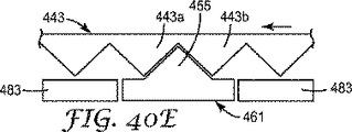
図40A〜40Eは、ハウジング409の円錐ハウジング部483と中央旋回部461上の斜面突起455との間の相互作用を模式的にかつ連続的に示す。図40Aは、円錐状の10の位の数字の1つを表示するために、10の位の円錐408が回転により所定の位置に固定されたときの斜面突起部455と鋸歯状配列443との関係を示す(例えば、図37および38に示す配列など)。10の位の円錐408が視認ウィンドウ472に示される10の位の数字を変えるために反時計回りに回転すると、鋸歯状配列443の歯443aは左に動き(図40Bに示す)、斜面突起部455を押し、ランプにランプを重ねる、それにより、外側へ曲がる(図40Bに示すように、下方へ)。歯443aの先端が斜面突起部455の先端と接触するとき、図40Cに示すように(および図37Bおよび38Bにさらに示す)、中央旋回部461は、円錐ハウジング部443に対してその最も外側の位置で曲がる。10の位のリング408の継続する反時計回りの移動は、鋸歯状配列443の歯443aを斜面突起部455を通過してランプの上にランプを重ねて、移動させ、これによって、干渉範囲を減少させ、中央旋回部461が10の位の円錐408に向かって(または、図40Dに示すように、上向きに)後に曲がることが可能になる。10の位の単位408の回転により10の位の数字が変わると、斜面突起部455は、鋸歯状配列443の歯443aと隣の歯443bとの間に配置され、それによって、10の位の円錐408の前進または逆移動を防ぐ(ユニット回転リング407の回転に応じて円錐の回転がもたらされるまでの間)。
40A-40E schematically and continuously show the interaction between the
結果的に、10の位の円錐408のインフィル要素447は、ハウジング409上のランプ459との隣接部内へ回転していく。この隣接に続いて(ユニット回転リングが1の位の数字として「9」を示したとき)、ユニット回転リング408が最後の10の位の計数を完了すると、突出した楕円状つまみ468は、10の位の円錐408上の放射状スポーク496をそれ以上動かすことができない。従って、ユニット回転リング407は、吸入器のさらなる作動にかかわらず、10の位の円錐408が10の位の数字としての「0」に到達すると、1の位の数字としての「0」を超えてさらに前進することが不可能になる。
As a result, the
本質において、図31〜40の実施形態に示す本発明の投与量カウンター402は、以下の方法で機能する。利用者が、エアゾール容器をアクチュエータハウジングへと下方に押すことにより吸入器を作動させるとき、バルブ口金は下方に押すためにインデクサー404と係合する。インデクサー404は係合し、それからユニットティースリング405を回転させる。ユニット回転リング407がユニットティースリング405に回転連結するため、ユニットティースリング405も同様に回転する。エアゾール容器がその中の薬剤の単回投与量を完了するために上下往復動をするため、インデクサー404およびユニットティースリング405は、ユニット回転リング407に対してさらに上下往復動をする。ユニットティースリング405の完全な上下往復動がユニット回転リング407を軸線422上で回転させるとき、ユニット回転リング407は、その位置で1の位の単回カウント変化する。ユニット回転リング407の回転は、ユニット回転リング407上のつまみ468と10の位の円錐408上のスポーク496の1つとの係合により、10の位の円錐408の回転につながる。しかし、10の位の円錐408は、カウントの10の位の変化を示すために、ユニット回転リング407に対して周期的にのみ回転する(例えば、10の位の円錐408はユニット回転リング407の動き10回に対して1回の割合でのみ動く)。ユニット回転リング407が1の位のカウントを10回数える度に、10の位の円錐408は、それについて表示される10の位のカウントを変えるために1つ位置をずらして指数付けされる。
In essence, the
投与量カウンターの第5の実施形態は図41〜47に示す。本実施形態は、投与量カウンター502として参照され(図45Aおよび45B参照)、カウンターの構成部品の逆移動を防ぐための機構が修正されたこと以外は、第3の実施形態と概ね同様である。10の位の円錐は、これ以上、ハウジングの円錐ハウジング部内の丸穴を通して見ることのできるスプラインを有さない。代わりに、10の位の列は、ハウジングの内面上の涙形状突起部と係合するために配置された涙形状凹所の環状配列を有する。さらに、本実施形態の10の位の円錐および対応するハウジングならびにユニット回転リングは、ハウジング上の涙形状突起部を備える涙形状凹所の1つと係合および解放するために回転する10の位の円錐のロッキング運動を可能にするように構成されている。 A fifth embodiment of the dose counter is shown in FIGS. This embodiment is referred to as a dose counter 502 (see FIGS. 45A and 45B) and is generally similar to the third embodiment except that the mechanism for preventing reverse movement of the counter components is modified. . The tenth cone no longer has a spline visible through a round hole in the conical housing portion of the housing. Instead, the tenth row has an annular array of tear-shaped recesses arranged to engage tear-shaped protrusions on the inner surface of the housing. Further, the tens cone and the corresponding housing and unit rotation ring of this embodiment are rotated to engage and release one of the tear-shaped recesses comprising a tear-shaped protrusion on the housing. Constructed to allow cone rocking motion.
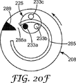
図41〜43は、第5の実施形態の投与量カウンター502の10の位の円錐508を示す。錐面584の頂点から見たとき、10の位の円錐508は、10の位の円錐508の外側錐面584の周りに降順時計回りに配列されている12〜0の数字を有する(例えば、12 11 10 9 8 7 6 5 4 3 2 1 0の順)。数字の読み取り方向は、10の位の円錐8上の方向と同様である。10の位の円錐508上において、錐面584は、10の位の円錐508の外周辺縁に隣接するバンド内のみで延びる。同心的にバンド内において、10の位の円錐508は、円錐面584に隣接し、10の位の円錐508の回転の軸線537に垂直に延びる環状面535を有する。涙形状凹所539の環状配列537は、環状面535上に配置される。各涙形状凹所539は、10の位の円錐508の軸線537から放射状に外側へ向いたより狭い先端を有する。同心的に環状面535内において、10の位の円錐508は、凹所541が10の位の円錐508の最も深く、近い軸線537であるように傾斜した環状凹所541を有する。環状凹所541は、10の位の円錐508の軸線537と同軸である突出した隆起543と接続し、囲む。狭い放射状インフィル要素545は、外側円錐面584上の10の位の数字により指示されて、約「6時」の位置において、環状面535と隆起543との間の凹所541を埋める。
FIGS. 41-43 show the
10の位の円錐508の内側面595は、10の位の円錐308の内側面395と同様に(および10の位の円錐408の内側面495と同様に)形成され、放射状スポーク596およびスピンドル597を支持する(図43参照)。
The
第5の実施形態では、ハウジング509が提供され、ここでもまた、ハウジングから下方に延びる前脚566およびその上の視認ウィンドウ572を備える概ね円筒体562を有する。ハウジング309と同様に、ハウジング509は、同様に形成され、ハウジング309のドア枠機構376(投与量カウンター502用のふたにハウジング509を留めるため)と同じ機能を果たすためにその上に複数(例えば、3つ)のドア枠機構576を有する。ハウジング509は、アクチュエータハウジングのノズルブロックを収容するためのシェルフを通過する中央穴582を有する横方向シェルフ581を有する。
In a fifth embodiment, a
その後側において(視認ウィンドウ572を含むとして画定される)、図45Aおよび45Bに示すように、ハウジング509は、そこから下方に延びる円錐ハウジング部583を有し、内部に10の位の円錐508を収容するように設計されている。従って、10の位の円錐508は、ハウジング509の後部から斜め前方および斜め上方に向けられた概ね軸線回りに回転することが可能である。本実施形態においてのハウジング409の軸線522(図45Aおよび45B参照)に対する10の位の円錐508の軸線537の関係は、図示し、記述した第3の実施形態の同じ構成部品の軸線と同様である(図45Aおよび45Bを図26と比較)。しかし、下記で説明するように、10の位の円錐508の回転中、軸線537はハウジング509の軸線522に対して方向をわずかに変えるように、円錐は、ハウジング509に相対して揺れ、または揺動する(例えば、α1はα2よりも大きい、図45に示す、α1と図45に示すβ2の角度の比較)。円錐ハウジング583は、環状面535および突起541以外の10の位の円錐508の外側に概ね合致するように内側に成形されている。図44で明らかなように、円錐ハウジング部583は、10の位の円錐508の環状面535および凹所541に対応する概ね平らな表面551を有する。涙形状突起部553は、10の位の円錐508の環状面535に対応する最も低い位置において平面551から内側へ延び、10の位の円錐508上の13の涙形状凹所539の各々と合致するように成形されている。ランプ55は、平面551から内側に、涙形状突起部553から放射状に内側に、および周辺にそこからオフセットでさらに突出する。ランプ555のインフィル要素545との係合をもたらすために10の位の円錐508が十分に回転したとき、ランプ55は、インフィル要素545に隣接するために十分に内側へ突出するように設計されている。これは、投与量カウンター502のカウンター要素のゼロ位置に対応する。円錐ハウジング部583は、10の位の円錐508の隆起597を収容するために成形された穴557をさらに有する。穴557の上方において、円錐ハウジング部583の一部は、10の位の円錐508およびハウジング509のアセンブリを容易にする対角カットアウトを有する。アセンブリの際に、隆起543はハウジング509内の元の位置に留まり、アセンブリの際、円錐ハウジング部583内のわずかなネック領域561を押しのけるように、10の位の円錐508の隆起543の直径は、カットアウト559および穴557は相互作用する。ハウジング309と同様に、円錐ハウジング部は、10の位の円錐508のスピンドル597の支持のために側溝部585と共にさらに備えられる。
On the rear side (defined as including the viewing window 572), as shown in FIGS. 45A and 45B, the
図45Aおよび図45Bは10の位の円錐508、ハウジング509および投与量カウンター502のその他の構成部品を示す。これらの他の構成部品は、望ましくないユニット回転リング507の修正以外は、図21〜30の実施形態に示す構成要素のような構成に概ね合致する。図47に示すように、ユニット回転リング507は、その底に環状基部546を有する。周辺リブ550は環状基部546上に配置される。周辺溝552は、リブ550と同軸の環状基部546の底面上にさらに備えられる。溝542は、10の位の円錐508に対してユニット回転リング507の全ての回転位置において、10の位の円錐508のスピンドル597を収容するために備えられる。しかし、本実施形態において、溝552は、放射状にわずかに溝552を越え、放射状に内側へ溝を過ぎ、およびユニット回転リング507の円筒部564内へ延びる2つの正反対でなだらかに放射状に開いたより深い凹所領域565を有する。凹所領域565は、下記のように、10の位の数字のカウントにおける変化を記録すると同時に、10の位の円錐508のスピンドル597の一時的な軸外位置への移動を可能にするように設計されている。
45A and 45B show the
上記のように、投与量カウンターの他の構成部品は、図21〜30の実施形態に示す構成部品のような構成に概ね合致する。従って、ふた503はふた303に対応し、インデクサー504はインデクサー304に対応し、ユニットティースリング505はユニットティースリング305に対応し、圧縮バネ506は圧縮バネ306に対応する。ふた503、インデクサー504、ユニットティースリング505、バネ506およびユニット回転リング507は、図45Aおよび45Bに示すように、10の位の円錐508およびハウジング509と共に組み立てられる。10の位の円錐508のユニット回転リング507とハウジング509との関係以外に、このアセンブリは、図21〜30の実施形態に示すものと概ね同一である。ユニット回転リング507の指数付けは、図21〜30における実施形態にあるように、図41〜47における実施形態と同様の方法で達成される。さらに、10の位の円錐508の指数付けは、図21〜30における実施形態にあるように、図41〜47における実施形態と同様の方法で達成される。図29A〜29Dに模式的に示した方法のように、10の位の円錐508のスポーク596は、ユニット回転リング507上のつまみ568(図47参照)により周期的に係合し、前進する(および図39A〜39Eに同様の構造を示す)。
As noted above, other components of the dose counter generally conform to configurations such as those shown in the embodiment of FIGS. Accordingly, the
外側円筒面566は、ユニット回転リング507の1の位の表示を有し、視認ウィンドウ572を通して視認可能である。10の位の円錐508は、その外側面584上の10の位の表示を有する。投与量カウンター502内に組み立てるとき、表面566上の表示および表面584は、利用者に代表的な投与カウントを示すために、共通視認領域において視認ウィンドウ572内で接して配列される。表示体支持面は、前述の実施形態においての同様の構造のもののように配列される。
The outer
図45Aおよび45B(および図46A〜46C)に示すように、10の位の円錐508は、動揺または軸線から離れ、視認ウィンドウ572において1の位の番号から次の10の位の数字の表示に指数付けする。ユニット回転リング507のつまみ568が10の位の円錐508の放射状スポーク596の1つと係合するとき、10の位の円錐508は、軸線537回りに回転する。涙形状突起553が涙形状凹所539のある場所から移動することにより、この回転は軸外移動になる。凹所領域565は、10の位の円錐508のスピンドル597は、10の位の円錐508のスピンドル597が軸外旋回することを可能にし、10の位の円錐508のそのような軸外回転移動を可能する。10の位の円錐508の回転は、ユニット回転リング507の回転に応じて完了するため、次の涙形状凹所539円錐ハウジング部583の涙形状突起部553との位置合わせを始める。ユニット回転リング307が回転を続けるため、凹所領域565は、スピンドル537と係合した場所から移動し、スピンドルは、ここでもまた、スピンドル597に沿い、軸線に戻す(ユニット回転リング507の次の1の位の数字のカウント9回分が残る)溝522の中へ動く。
As shown in FIGS. 45A and 45B (and FIGS. 46A-46C), the
図46Aおよび46Bは、涙形状凹所539の1つが円錐ハウジング部583の涙形状突起553と係合しているときの10の位の円錐508の位置に対応する(図45Bにさらに示す)。図46Cは、10の位の円錐508の涙形状凹所539のどれもが円錐ハウジング部583の涙形状突起部553と係合していないとき(図45Aにさらに示す)のユニット回転リング507に対する10の位の円錐508の軸外移動(凹所領域により可能になる)を示す。
46A and 46B correspond to the position of the
結果的に、10の位の円錐508のインフィル要素545は、ハウジング509上のランプ555との隣接部内へ回転していく。この隣接に続いて(ユニット回転リングが1の位の数字として「9」を示したとき)、ユニット回転リング508が最後の10の位のカウントを完了するため、突出した楕円状つまみ568は、10の位の円錐508上の放射状スポーク596をそれ以上動かすことができない。従って、ユニット回転リング507は、吸入器のさらなる作動にかかわらず、10の位の円錐508が10の位の数字としての「0」に到達するため、1の位の数字としての「0」を超えてさらに前進することが不可能になる。
As a result, the
本質において、図41〜47の実施形態に示す本発明の投与量カウンター502は、以下の方法で機能する。利用者が、エアゾール容器をアクチュエータハウジングへと下方に押すことにより吸入器を作動させるとき、バルブ口金は下方に押すためにインデクサー504と係合する。インデクサー504は係合し、それからユニットティースリング505を回転させる。ユニット回転リング507がユニットティースリング505に回転連結するため、ユニットティースリング505も同様に回転する。エアゾール容器がその中の薬剤の単回投与量を完了するために上下往復動をするため、インデクサー504およびユニットティースリング505は、ユニット回転リング507に対してさらに上下往復動をする。ユニットティースリング505の完全な上下往復動がユニット回転リング507を軸線522上で回転させるとき、ユニット回転リング507は、その位置で1の位の単回カウント変化する。ユニット回転リング507の回転は、ユニット回転リング507上のつまみ568と10の位の円錐508上のスポーク596の1つとが係合する際に、10の位の円錐508の回転につながる。しかし、10の位の円錐508は、カウントの10の単位の変化を示すために、ユニット回転リング507に対して周期的にのみ回転する(例えば、10の位の円錐508はユニット回転リング507の動き10回に対して1回の割合でのみ動く)。ユニット回転リング507が1の位の測定を10回数える度に、10の位の円錐508は、それについて表示される10の位のカウントを変えるために1つ位置をずらして指数付けされる。
In essence, the
各実施形態において、投与量カウンターの構成部品のそれらの部分は係合のために設計され(例えば、インデクサー上およびユニットティースリング上の歯の内側リング上の鋸歯状突起部、周辺縁またはユニット回転リング上の楕円状つまみおよびペグまたは10の位の円錐のスポーク)耐久性がある一方、即座の相互作用を促進する十分に低摩擦な素材(例えば、好適な重合体)から形成されている。 In each embodiment, those portions of the dose counter components are designed for engagement (e.g., serrated protrusions, peripheral edges or unit rotation on the indexer and on the inner ring of teeth on the unit teeth ring) It is made of a sufficiently low friction material (eg, a suitable polymer) that is durable, while being durable (ellipsoidal tabs and pegs on the ring or 10-degree conical spokes).
好ましい実施形態を参照しながら本発明を説明してきたが、本発明の精神及び範囲から逸脱しない形態及び詳細の変更を行えることが、当業者であれば理解できるであろう。 While the invention has been described with reference to preferred embodiments, workers skilled in the art will recognize that changes may be made in form and detail without departing from the spirit and scope of the invention.
本発明は、添付図面を参照してさらに説明され、ここで同様の構造は種々の図にわたって同じ参照数字によって示される。 The invention will be further described with reference to the accompanying drawings, wherein like structures are designated by like reference numerals throughout the various views.
図面は、本発明のいくつかの実施形態を記載するが、他の実施形態もまた開示の中で述べられたように企図される。すべての場合において、本開示は、代表例によって本発明を表しており、限定を意味するものではない。本発明の原理の範囲及び精神の中で、多くの他の修正及び実施形態が、当業者によって考案され得ることを理解されたい。 While the drawings describe several embodiments of the present invention, other embodiments are also contemplated as described in the disclosure. In all cases, this disclosure presents the invention by way of representation and is not meant to be limiting. It should be understood that many other modifications and embodiments can be devised by those skilled in the art within the scope and spirit of the principles of the present invention.
Claims (7)
円錐面を有し、第1軸線回りに回転可能な第1カウント表示器と、
円筒面を有し、第2軸線回りに回転可能な第2カウント表示器と、を備え、
前記第2軸線は、前記第1軸線に対して鈍角を成して配置され、
前記円錐面および前記円筒面は、薬剤投与量カウントの少なくとも一部分をまとめて示すために、共通視認領域において整列する、投与量カウンター。A dose counter for use with a device suitable for metering a drug,
A first count indicator having a conical surface and rotatable about a first axis;
A second count indicator having a cylindrical surface and rotatable about a second axis,
The second axis is disposed at an obtuse angle with respect to the first axis;
The dose counter, wherein the conical surface and the cylindrical surface are aligned in a common viewing area to collectively represent at least a portion of a drug dose count.
円錐面を有し、第1軸線回りに回転可能な第1カウント表示器と、
円筒面を有し、第2軸線回りに回転可能な第2カウント表示器と、を備え、
前記第1軸線および前記第2軸線は、互いに同軸、平行および垂直のいずれの形態でも配置されず、
前記円錐面および前記円筒面は、薬剤投与量カウントの少なくとも一部分をまとめて示すために、共通視認領域において整列する、投与量カウンター。A dose counter for use with a device suitable for metering a drug,
A first count indicator having a conical surface and rotatable about a first axis;
A second count indicator having a cylindrical surface and rotatable about a second axis,
The first axis and the second axis are not arranged in any of the coaxial, parallel and vertical forms,
The dose counter, wherein the conical surface and the cylindrical surface are aligned in a common viewing area to collectively represent at least a portion of a drug dose count.
前記第1カウント表示器上の回転追従要素と、をさらに含み、
前記第2カウント表示器の回転によって、前記第2カウント表示器上の回転開始要素が前記第1カウント表示器上の回転追従要素に係合し、それにより前記第2カウント表示器の回転範囲に応じて前記第1カウント表示器が回転させられる、請求項1又は2に記載の投与量カウンター。A rotation starting element on the second count indicator;
A rotation tracking element on the first count indicator,
Due to the rotation of the second count indicator, the rotation starting element on the second count indicator is engaged with the rotation following element on the first count indicator, so that the rotation range of the second count indicator is reached. 3. A dose counter according to claim 1 or 2, wherein the first count indicator is rotated accordingly.
前記第1カウント表示器上の回転追従要素と、をさらに含み、
前記回転制限要素および前記回転追従要素は、前記第1カウント表示器の回転を防ぐために、前記第2カウント表示器の回転中に時々係合する、請求項1〜3のいずれか1項に記載の投与量カウンター。A rotation limiting element on the second count indicator;
A rotation tracking element on the first count indicator,
4. The rotation limiting element and the rotation following element are sometimes engaged during rotation of the second count indicator to prevent rotation of the first count indicator. Dose counter.
前記第2カウント表示器上の回転追従要素と、をさらに含み、
前記第1カウント表示器の回転によって、前記第1カウント表示器上の回転開始要素が前記第2カウント表示器上の回転追従要素に係合し、それにより前記第1カウント表示器の回転範囲に応じて前記第2カウント表示器が回転させられる、請求項1又は2に記載の投与量カウンター。A rotation starting element on the first count indicator;
A rotation tracking element on the second count indicator,
Due to the rotation of the first count indicator, the rotation starting element on the first count indicator is engaged with the rotation follow-up element on the second count indicator, so that the rotation range of the first count indicator is reached. 3. A dose counter according to claim 1 or 2, wherein the second count indicator is rotated accordingly.
前記第2カウント表示器上の回転追従要素と、をさらに含み、
前記回転制限要素および前記回転追従要素は、前記第2カウント表示器の回転を防ぐために、前記第1カウント表示器の回転中に時々係合する、請求項1、2又は5に記載の投与量カウンター。A rotation limiting element on the first count indicator;
A rotation tracking element on the second count indicator,
6. A dose according to claim 1, 2 or 5, wherein the rotation limiting element and the rotation following element are sometimes engaged during rotation of the first count indicator to prevent rotation of the second count indicator. counter.
前記第3軸線は、前記第1軸線に対して鈍角を成して配置され、
前記円錐面および第3表示体支持面は、前記共通視認領域において薬剤投与量カウントをまとめて示すために、前記円筒面と組み合わされて整列する、請求項1〜6のいずれか1項に記載の投与量カウンター。A third count indicator that has a third display support surface and is rotatable about a third axis;
The third axis is disposed at an obtuse angle with respect to the first axis;
The said conical surface and the 3rd display body support surface are combined and aligned with the said cylindrical surface in order to show a medicine dosage count collectively in the said common visual recognition area | region, The alignment of any one of Claims 1-6. Dose counter.
Applications Claiming Priority (3)
| Application Number | Priority Date | Filing Date | Title |
|---|---|---|---|
| US74532606P | 2006-04-21 | 2006-04-21 | |
| US60/745,326 | 2006-04-21 | ||
| PCT/US2007/067056 WO2007124406A2 (en) | 2006-04-21 | 2007-04-20 | Dose counter |
Publications (3)
| Publication Number | Publication Date |
|---|---|
| JP2009534131A JP2009534131A (en) | 2009-09-24 |
| JP2009534131A5 JP2009534131A5 (en) | 2010-06-03 |
| JP5102285B2 true JP5102285B2 (en) | 2012-12-19 |
Family
ID=38625761
Family Applications (1)
| Application Number | Title | Priority Date | Filing Date |
|---|---|---|---|
| JP2009506785A Active JP5102285B2 (en) | 2006-04-21 | 2007-04-20 | Dosage counter |
Country Status (4)
| Country | Link |
|---|---|
| US (2) | US8479732B2 (en) |
| EP (1) | EP2010125B1 (en) |
| JP (1) | JP5102285B2 (en) |
| WO (1) | WO2007124406A2 (en) |
Families Citing this family (57)
| Publication number | Priority date | Publication date | Assignee | Title |
|---|---|---|---|---|
| US6082358A (en) | 1998-05-05 | 2000-07-04 | 1263152 Ontario Inc. | Indicating device for aerosol container |
| EP2010125B1 (en) | 2006-04-21 | 2017-01-04 | 3M Innovative Properties Company | Dose counter |
| FR2924351B1 (en) * | 2007-12-03 | 2011-09-30 | Valois Sas | DEVICE FOR DISPENSING FLUID PRODUCT |
| WO2009103711A1 (en) * | 2008-02-18 | 2009-08-27 | Glaxo Group Limited | Actuation counter |
| US8392020B2 (en) | 2008-02-29 | 2013-03-05 | Tension International, Inc. | Automated precision small object counting and dispensing system and method |
| CN102065940B (en) * | 2008-05-07 | 2014-06-11 | Map药物公司 | Dose counter with lockout mechanism |
| US8511478B2 (en) | 2008-08-22 | 2013-08-20 | Tension International, Inc. | Container dispersion wheel |
| WO2010022345A2 (en) | 2008-08-22 | 2010-02-25 | Robert Terzini | Container dispersion and filling system |
| FR2944707B1 (en) * | 2009-04-28 | 2013-08-09 | Valois Sas | METER FOR DEVICE FOR DISPENSING FLUID OR PULVERULENT PRODUCT. |
| GB0920499D0 (en) | 2009-11-23 | 2010-01-06 | 3M Innovative Properties Co | Dose counter |
| GB0921555D0 (en) * | 2009-12-09 | 2010-01-27 | 3M Innovative Properties Co | Dose indicator |
| WO2013045996A1 (en) * | 2011-09-26 | 2013-04-04 | Trudell Medical International | Dose counter and medication delivery device |
| EP2768480A1 (en) | 2011-10-21 | 2014-08-27 | Rigel Pharmaceuticals, Inc. | Method and device for administering xinafoate salt of n4-(2,2-difluoro-4h-benzo [1,4]oxazin-3-one) -6-yl]-5-fluoro-n2- [3- (methylaminocarbonylmethyleneoxy) phenyl]2,4-pyrimidinediamine |
| CN104203319B (en) * | 2012-01-23 | 2017-03-08 | 赛诺菲股份有限公司 | Dose counter mechanism and suction apparatus for suction apparatus |
| US20150306322A9 (en) * | 2012-01-23 | 2015-10-29 | Sanofi Sa | Inhalation Device |
| SG192310A1 (en) | 2012-02-02 | 2013-08-30 | Becton Dickinson Holdings Pte Ltd | Adaptor for coupling to a medical container |
| ES2681968T3 (en) * | 2012-02-02 | 2018-09-17 | Becton Dickinson Holdings Pte. Ltd. | Adapter that couples with a medical container |
| SG192312A1 (en) | 2012-02-02 | 2013-08-30 | Becton Dickinson Holdings Pte Ltd | Adaptor for coupling to a medical container |
| US8978278B1 (en) * | 2012-04-12 | 2015-03-17 | Martin Rossi | Toothbrush identifier |
| US20140053838A1 (en) * | 2012-07-12 | 2014-02-27 | Annaniy Berenshteyn | Dose counter assembly for inhaler |
| EP2692328A1 (en) | 2012-08-03 | 2014-02-05 | Becton Dickinson France | Dose counting device for coupling with a medical container |
| GB201215917D0 (en) * | 2012-09-06 | 2012-10-24 | 3M Innovative Properties Co | Improvements in or relating to dose indicators |
| EP2735300A1 (en) | 2012-11-26 | 2014-05-28 | Becton Dickinson France | Adaptor for multidose medical container |
| GB201308679D0 (en) * | 2013-05-14 | 2013-06-26 | 3M Innovative Properties Co | Actuator for an inhaler |
| US8807131B1 (en) | 2013-06-18 | 2014-08-19 | Isonea Limited | Compliance monitoring for asthma inhalers |
| GB201312448D0 (en) * | 2013-07-11 | 2013-08-28 | 3M Innovative Properties Co | Dose indicator or dose counter |
| JP1526207S (en) | 2013-08-05 | 2015-06-15 | ||
| DE102014114462A1 (en) | 2013-10-15 | 2015-04-16 | Alfred Von Schuckmann | Counter and handset with counter |
| GB201406047D0 (en) * | 2014-04-03 | 2014-05-21 | 3M Innovative Properties Co | Dose indicator or dose counter |
| GB201406046D0 (en) * | 2014-04-03 | 2014-05-21 | 3M Innovative Properties Co | Dose indicator or dose counter |
| ES2913297T3 (en) * | 2014-05-07 | 2022-06-01 | Boehringer Ingelheim Int | nebulizer |
| GB201421983D0 (en) * | 2014-12-10 | 2015-01-21 | Coalesce Product Dev Ltd | Improvements in counting devices |
| EP3368083A1 (en) | 2015-10-29 | 2018-09-05 | 3M Innovative Properties Company | Formulation and aerosol canisters, inhalers, and the like containing the formulation |
| DE102015120948A1 (en) | 2015-12-02 | 2017-06-08 | Alfred Von Schuckmann | Hand-held device for dispensing a pharmaceutical substance and counter and screw cap for such a hand-held device |
| US9928348B2 (en) | 2015-12-21 | 2018-03-27 | At&T Intellectual Property I, L.P. | Medicine dispensing system |
| KR101767409B1 (en) | 2016-11-16 | 2017-08-11 | 이상현 | Indication Of Dosing Frequency And Dosing dispenser |
| US11207477B2 (en) | 2017-05-17 | 2021-12-28 | Kindeva Drug Delivery L.P. | Formulation and aerosol canisters, inhalers, and the like containing the formulation |
| JP7242630B2 (en) * | 2017-07-21 | 2023-03-20 | ベーリンガー インゲルハイム インターナショナル ゲゼルシャフト ミット ベシュレンクテル ハフツング | nebulizer and reservoir |
| US11291182B2 (en) * | 2018-02-05 | 2022-04-05 | Nexfeed LLP | Device for facilitating and tracking the feeding of an animal |
| DE102018203618A1 (en) * | 2018-03-09 | 2019-09-12 | B. Braun Melsungen Ag | Dosing dispenser and housing structure for this |
| WO2019236397A1 (en) | 2018-06-07 | 2019-12-12 | 3M Innovative Properties Company | Fluticasone and vilanterol formulation and inhaler |
| JP2021527057A (en) | 2018-06-07 | 2021-10-11 | キンデーバ ドラッグ デリバリー リミティド パートナーシップ | Fluticasone and vilanterol preparations and inhalers |
| EP3880169A1 (en) | 2018-11-12 | 2021-09-22 | Kindeva Drug Delivery L.P. | Umeclidinium and vilanterol formulation and inhaler |
| WO2021064700A1 (en) | 2019-10-04 | 2021-04-08 | Lupin Limited | Event status apparatuses and related devices, systems, and methods |
| USD1006212S1 (en) * | 2020-04-03 | 2023-11-28 | Aptar Radolfzell Gmbh | Evaluation unit for inhalers |
| CN111860750B (en) * | 2020-08-24 | 2022-06-21 | 万通(苏州)定量阀系统有限公司 | Counting indicator for aerosol valve |
| US11877848B2 (en) | 2021-11-08 | 2024-01-23 | Satio, Inc. | Dermal patch for collecting a physiological sample |
| US12029562B2 (en) | 2021-04-14 | 2024-07-09 | Satio, Inc. | Dermal patch system |
| US12048543B2 (en) | 2021-11-08 | 2024-07-30 | Satio, Inc. | Dermal patch for collecting a physiological sample with removable vial |
| US12023156B2 (en) | 2021-10-13 | 2024-07-02 | Satio, Inc. | Dermal patch for collecting a physiological sample |
| US11964121B2 (en) | 2021-10-13 | 2024-04-23 | Satio, Inc. | Mono dose dermal patch for pharmaceutical delivery |
| US12053284B2 (en) | 2021-11-08 | 2024-08-06 | Satio, Inc. | Dermal patch for collecting a physiological sample |
| US12036185B2 (en) | 2021-07-19 | 2024-07-16 | Optum, Inc. | System and method to count pills |
| EP4398879A1 (en) | 2021-09-08 | 2024-07-17 | Kindeva Drug Delivery L.P. | Metered dose inhalers and solution compositions |
| WO2024181972A1 (en) | 2022-03-01 | 2024-09-06 | Kindeva Drug Delivery L.P. | Metered dose inhalers and high-dose suspensions |
| WO2024182699A1 (en) | 2023-03-02 | 2024-09-06 | Kindeva Drug Delivery L.P. | Metered dose inhalers and solutions including cannabinoids in hfo-1234ze(e) |
| WO2024182686A1 (en) | 2023-03-02 | 2024-09-06 | Kindeva Drug Delivery L.P. | Metered dose inhalers and solutions including cannabinoids in hfa-152a |
Family Cites Families (55)
| Publication number | Priority date | Publication date | Assignee | Title |
|---|---|---|---|---|
| US3402692A (en) * | 1966-12-23 | 1968-09-24 | Bourns Inc | Brake and turns-counting means for rotary instrument |
| US3822808A (en) * | 1973-03-20 | 1974-07-09 | Tokico Ltd | Fuel supplying apparatus having a reversible plate type flow indicator |
| US4561565A (en) * | 1983-10-28 | 1985-12-31 | Deere & Company | Rate adjustment for chemical meter |
| AU598250B2 (en) | 1986-04-25 | 1990-06-21 | Glaxo Group Limited | Indicating device |
| US5718355A (en) | 1989-02-03 | 1998-02-17 | Senetics, Inc. | Indicator device responsive to axial force for use with inhaler |
| FR2665557B1 (en) * | 1990-07-31 | 1992-11-20 | Sam Atoms Monaco | MECHANICAL COUNTING DEVICE OF NUMBER OF TURNS OF A ROTATING AXIS BY ROTARY DRIVE OF EXHAUST OF AN INCLINED ELEMENT. |
| DE4027670A1 (en) | 1990-08-31 | 1992-03-05 | Pfeiffer Erich Gmbh & Co Kg | DISCHARGE DEVICE FOR MEDIA |
| WO1993003782A1 (en) | 1991-08-15 | 1993-03-04 | Bon F Del | Inhaler |
| JP2924924B2 (en) | 1992-12-18 | 1999-07-26 | シェリング・コーポレーション | Inhaler for powdered drugs |
| US5564414A (en) | 1994-05-26 | 1996-10-15 | Walker; William F. | Pressurized and metered medication dose counter on removable sleeve |
| FR2721106B1 (en) * | 1994-06-10 | 1996-09-13 | Step | Dose counter for inhalers. |
| CA2239292C (en) | 1995-12-07 | 2003-09-30 | Jago Pharma Ag | Inhalator designed to provide multiple doses of a dry pharmacological powder |
| FR2750780B1 (en) | 1996-07-05 | 1998-10-30 | Valois | DOSER COUNTER |
| GB2320489A (en) | 1996-12-20 | 1998-06-24 | Norton Healthcare Ltd | Inhaler dose counter |
| SE9700939D0 (en) | 1997-03-14 | 1997-03-14 | Astra Ab | Powder inhales III |
| ES2229495T3 (en) * | 1997-05-23 | 2005-04-16 | Pa Knowledge Limited | INHALING DEVICE. |
| TW533865U (en) | 1997-06-10 | 2003-05-21 | Glaxo Group Ltd | Dispenser for dispensing medicament and actuation indicating device |
| US6142339A (en) * | 1998-01-16 | 2000-11-07 | 1263152 Ontario Inc. | Aerosol dispensing device |
| DE69918267T2 (en) | 1998-01-16 | 2005-07-28 | 1263152 Ontario Inc., London | DISPLAY DEVICE FOR USE WITH A DISPENSER |
| GB9807558D0 (en) | 1998-04-09 | 1998-06-10 | Bason Neil P | An indicator device |
| US6729330B2 (en) | 1998-05-05 | 2004-05-04 | Trudell Medical International | Indicating device for aerosol container |
| DE29814647U1 (en) | 1998-08-14 | 1999-12-23 | Josef Wischerath Gmbh & Co. Kg, 50259 Pulheim | Inhaler with a metering device |
| DE19846382C1 (en) | 1998-10-08 | 2000-07-06 | Pari Gmbh | Counter and its use in inhalers, nebulizers or similar metered dose inhalers |
| GB2348928B (en) | 1999-04-07 | 2001-10-31 | Bespak Plc | Improvements in or relating to dispensing apparatus |
| FR2799858B1 (en) | 1999-10-19 | 2002-01-18 | Valois Sa | DOSAGE COUNTER AND FLUID PRODUCT DISPENSER INCORPORATING SUCH A COUNTER |
| GB9924949D0 (en) | 1999-10-22 | 1999-12-22 | Innovata Biomed Ltd | Inhaler |
| SE515858C2 (en) | 1999-11-26 | 2001-10-22 | Ernst Hoerlins Ingenjoersbyra | Counter and spray dose inhaler with the counter |
| GB2372542B (en) * | 2001-02-23 | 2003-08-20 | Bespak Plc | Dosage counting devices |
| GB2372543B (en) | 2001-02-23 | 2003-08-20 | Bespak Plc | Dosage counting devices |
| FR2830527B1 (en) * | 2001-10-04 | 2004-08-27 | Valois Sa | DOSAGE COUNTER FOR A FLUID PRODUCT DISPENSER |
| ES2321601T3 (en) | 2002-06-21 | 2009-06-09 | Glaxo Group Limited | DRIVE INDICATOR FOR DISTRIBUTOR DEVICE. |
| PT1658872E (en) | 2002-07-31 | 2011-05-12 | Chiesi Farma Spa | Powder inhaler |
| US7322352B2 (en) | 2002-09-21 | 2008-01-29 | Aventis Pharma Limited | Inhaler |
| GB0222023D0 (en) | 2002-09-21 | 2002-10-30 | Aventis Pharma Ltd | Inhaler |
| WO2004041334A2 (en) | 2002-11-04 | 2004-05-21 | Bang & Olufsen Medicom A/S | Device for dispension |
| US6993219B2 (en) | 2003-03-13 | 2006-01-31 | Lucent Technologies Inc. | Waveguide/MEMS switch |
| FR2854878B1 (en) | 2003-05-15 | 2006-03-31 | Valois Sas | FLUID PRODUCT DISPENSER. |
| US7222736B1 (en) * | 2003-06-13 | 2007-05-29 | James Seijas | Device and method for indicating scheduled doses |
| US7703454B2 (en) | 2003-07-14 | 2010-04-27 | Vortran Medical Technology | Inhaler with breath actuated dose counter |
| US8045788B2 (en) | 2003-07-14 | 2011-10-25 | August Technology Corp. | Product setup sharing for multiple inspection systems |
| US7621273B2 (en) | 2003-10-28 | 2009-11-24 | Trudell Medical International | Indicating device with warning dosage indicator |
| GB0328635D0 (en) * | 2003-12-10 | 2004-01-14 | 3M Innovative Properties Co | Dose counter for dispensers |
| US7100530B2 (en) | 2003-12-15 | 2006-09-05 | Trudell Medical International, Inc. | Dose indicating device |
| CA2555347A1 (en) * | 2004-02-16 | 2005-09-01 | Stephen Edward Augustyn | Counter for use with a medicament dispenser |
| FR2869685B1 (en) | 2004-04-29 | 2006-07-28 | Valois Sas | INDICATOR FOR DEVICE FOR DISPENSING FLUID OR PULVERULENT PRODUCT |
| GB2414187B (en) | 2004-05-21 | 2007-03-07 | Bespak Plc | Dispensing apparatus |
| US7543582B2 (en) * | 2004-09-20 | 2009-06-09 | Trudell Medical International | Dose indicating device with display elements attached to container |
| FR2883400B1 (en) * | 2005-03-16 | 2007-06-15 | Valois Sas | DOSAGE INDICATING DEVICE FOR DISPENSING FLUID OR PULVERULENT PRODUCTS |
| US7404373B2 (en) * | 2005-10-03 | 2008-07-29 | Keith Bailey | Portable game scoreboard |
| GB2434753B (en) | 2005-11-22 | 2008-03-12 | Bespak Plc | Aerosol dispensing apparatus |
| US8020507B2 (en) * | 2006-04-21 | 2011-09-20 | Tara Strong | Food storage and management system |
| EP2010125B1 (en) * | 2006-04-21 | 2017-01-04 | 3M Innovative Properties Company | Dose counter |
| GB2448839B (en) | 2006-05-26 | 2009-05-27 | Consort Medical Plc | Improvements in or relating to dispensing apparatus |
| DE102006040194A1 (en) | 2006-08-28 | 2008-03-06 | Rpc Formatec Gmbh | Hand-held unit for portioned release of e.g. aerosol inhaling drugs, has step switching system inserted in mouthpiece-turned side of housing boundary wall by opening and fastened to counter bearing |
| GB0921555D0 (en) * | 2009-12-09 | 2010-01-27 | 3M Innovative Properties Co | Dose indicator |
-
2007
- 2007-04-20 EP EP07760991.5A patent/EP2010125B1/en active Active
- 2007-04-20 US US12/297,942 patent/US8479732B2/en active Active
- 2007-04-20 JP JP2009506785A patent/JP5102285B2/en active Active
- 2007-04-20 WO PCT/US2007/067056 patent/WO2007124406A2/en active Application Filing
-
2013
- 2013-07-02 US US13/933,148 patent/US9089661B2/en active Active
Also Published As
| Publication number | Publication date |
|---|---|
| EP2010125B1 (en) | 2017-01-04 |
| EP2010125A2 (en) | 2009-01-07 |
| US8479732B2 (en) | 2013-07-09 |
| US20130291861A1 (en) | 2013-11-07 |
| EP2010125A4 (en) | 2014-05-07 |
| WO2007124406A2 (en) | 2007-11-01 |
| JP2009534131A (en) | 2009-09-24 |
| WO2007124406A3 (en) | 2008-02-07 |
| US20090173346A1 (en) | 2009-07-09 |
| US9089661B2 (en) | 2015-07-28 |
Similar Documents
| Publication | Publication Date | Title |
|---|---|---|
| JP5102285B2 (en) | Dosage counter | |
| EP1991295B1 (en) | Apparatus for metered dosed dispensing | |
| JP4423457B2 (en) | Dispenser and administration device display device | |
| JP4629947B2 (en) | Inhalation device with administration frequency counter | |
| AU2004304935B2 (en) | Dose counter for dispensers | |
| CA2789270C (en) | A dispensing device for use in dispensing metered dosages | |
| US7191918B2 (en) | Dosage counting devices | |
| US7407066B2 (en) | Dosage counting devices | |
| CN102892448B (en) | For the dose counter of inhaler, inhaler and axle thereof | |
| AU2001260379A1 (en) | Inhaler with a dose counter | |
| WO2007077450A2 (en) | Dose counter with an odometer type display |
Legal Events
| Date | Code | Title | Description |
|---|---|---|---|
| A521 | Request for written amendment filed |
Free format text: JAPANESE INTERMEDIATE CODE: A523 Effective date: 20100414 |
|
| A621 | Written request for application examination |
Free format text: JAPANESE INTERMEDIATE CODE: A621 Effective date: 20100414 |
|
| A977 | Report on retrieval |
Free format text: JAPANESE INTERMEDIATE CODE: A971007 Effective date: 20120202 |
|
| A131 | Notification of reasons for refusal |
Free format text: JAPANESE INTERMEDIATE CODE: A131 Effective date: 20120207 |
|
| A601 | Written request for extension of time |
Free format text: JAPANESE INTERMEDIATE CODE: A601 Effective date: 20120507 |
|
| A602 | Written permission of extension of time |
Free format text: JAPANESE INTERMEDIATE CODE: A602 Effective date: 20120514 |
|
| A521 | Request for written amendment filed |
Free format text: JAPANESE INTERMEDIATE CODE: A523 Effective date: 20120807 |
|
| TRDD | Decision of grant or rejection written | ||
| A01 | Written decision to grant a patent or to grant a registration (utility model) |
Free format text: JAPANESE INTERMEDIATE CODE: A01 Effective date: 20120828 |
|
| A01 | Written decision to grant a patent or to grant a registration (utility model) |
Free format text: JAPANESE INTERMEDIATE CODE: A01 |
|
| A61 | First payment of annual fees (during grant procedure) |
Free format text: JAPANESE INTERMEDIATE CODE: A61 Effective date: 20120927 |
|
| FPAY | Renewal fee payment (event date is renewal date of database) |
Free format text: PAYMENT UNTIL: 20151005 Year of fee payment: 3 |
|
| R150 | Certificate of patent or registration of utility model |
Free format text: JAPANESE INTERMEDIATE CODE: R150 Ref document number: 5102285 Country of ref document: JP Free format text: JAPANESE INTERMEDIATE CODE: R150 |
|
| R250 | Receipt of annual fees |
Free format text: JAPANESE INTERMEDIATE CODE: R250 |
|
| R250 | Receipt of annual fees |
Free format text: JAPANESE INTERMEDIATE CODE: R250 |
|
| R250 | Receipt of annual fees |
Free format text: JAPANESE INTERMEDIATE CODE: R250 |
|
| R250 | Receipt of annual fees |
Free format text: JAPANESE INTERMEDIATE CODE: R250 |
|
| R250 | Receipt of annual fees |
Free format text: JAPANESE INTERMEDIATE CODE: R250 |
|
| R250 | Receipt of annual fees |
Free format text: JAPANESE INTERMEDIATE CODE: R250 |
|
| S111 | Request for change of ownership or part of ownership |
Free format text: JAPANESE INTERMEDIATE CODE: R313113 |
|
| R350 | Written notification of registration of transfer |
Free format text: JAPANESE INTERMEDIATE CODE: R350 |
|
| RD02 | Notification of acceptance of power of attorney |
Free format text: JAPANESE INTERMEDIATE CODE: R3D02 |
|
| R250 | Receipt of annual fees |
Free format text: JAPANESE INTERMEDIATE CODE: R250 |
|
| R250 | Receipt of annual fees |
Free format text: JAPANESE INTERMEDIATE CODE: R250 |
|
| R250 | Receipt of annual fees |
Free format text: JAPANESE INTERMEDIATE CODE: R250 |