JP5101962B2 - Image coding apparatus, control method therefor, and computer program - Google Patents
Image coding apparatus, control method therefor, and computer program Download PDFInfo
- Publication number
- JP5101962B2 JP5101962B2 JP2007244444A JP2007244444A JP5101962B2 JP 5101962 B2 JP5101962 B2 JP 5101962B2 JP 2007244444 A JP2007244444 A JP 2007244444A JP 2007244444 A JP2007244444 A JP 2007244444A JP 5101962 B2 JP5101962 B2 JP 5101962B2
- Authority
- JP
- Japan
- Prior art keywords
- sub
- block
- blocks
- encoding
- encoded data
- Prior art date
- Legal status (The legal status is an assumption and is not a legal conclusion. Google has not performed a legal analysis and makes no representation as to the accuracy of the status listed.)
- Expired - Fee Related
Links
Images


Description
本発明は画像の符号化技術に関するものである。 The present invention relates to encoding technology of image.
一般に、圧縮符号化技術として知られているものに、JPEGがある。JPEGは、符号化対象の画像データを複数画素で構成されるブロックに分割し、各ブロックをDCT、量子化、そして、エントロピー符号化を行なうものである。この一連の処理において、特に量子化処理で用いる量子化ステップ値が、符号量を決める主要なパラメータとなる。すなわち、量子化ステップ値を大きな値にすると、DCT係数値が0もしくはそれに近い値になり、圧縮率が上げることができる。但し、量子化ステップ値を大きくすればするほど、符号化前のオリジナル画像に対する差が大きくなり、画質劣化として現れる。 In general, JPEG is known as a compression encoding technique. In JPEG, image data to be encoded is divided into blocks each composed of a plurality of pixels, and each block is subjected to DCT, quantization, and entropy encoding. In this series of processing, especially the quantization step value used in the quantization processing is a main parameter for determining the code amount. That is, when the quantization step value is set to a large value, the DCT coefficient value becomes 0 or a value close thereto, and the compression rate can be increased. However, the larger the quantization step value, the greater the difference from the original image before encoding, which appears as image quality degradation.
画質劣化を防止しつつ符号化効率を高める技術として、特許文献1が知られている。この文献によれば、入力画像をブロックに分割し、差分予測無しに符号化処理した結果と、差分予測を行ったブロックに対して符号化処理した結果との符号量を比較し符号量の少ない手法を各ブロックで選択するものである。
しかしながら、非可逆の符号化手法において、過度に高い圧縮率で符号化を行うと、画像情報が多く欠落してしまい、画質劣化が目立ってしまう問題がある。先に示した従来の符号化手法では、ある程度の画像品位を保つことと、符号量の削減を両立することに対して未だ改善の余地がある。 However, in an irreversible encoding method, if encoding is performed at an excessively high compression rate, a large amount of image information is lost, and there is a problem that image quality deterioration is conspicuous. In the conventional coding method described above, there is still room for improvement with respect to both maintaining a certain level of image quality and reducing the amount of codes.
本発明はかかる課題に鑑みなされたものであり、画質劣化を抑制しつつ、これまで以上の情報を削減することを可能ならしめる画像符号化技術を提供しようとするものである。 The present invention has been made in view of such problems, and an object of the present invention is to provide an image encoding technique that makes it possible to reduce more information than before while suppressing deterioration in image quality.
この課題を解決するため、例えば本発明の画像符号化装置は以下の構成を備える。すなわち、
画像データを圧縮符号化する画像符号化装置であって、
水平及び垂直方向に複数の画素で構成されるサイズのブロックを単位に、画像データを入力する入力手段と、
前記入力手段で入力した着目ブロックについて、p×q画素(p,qは正の整数であり、少なくとも一方は2以上)のサイズのウインドウを単位とし、各ウインドウ内の相対的に同じ位置の画素データで構成されるサブブロックを生成することにより、p×q個のサブブロックを取得する生成手段と、
前記p×q個のサブブロックを符号化する符号化手段とを備え、
前記符号化手段は、前記p×q個のサブブロックの符号化データの総符号量が予め設定された許容符号化データ量を超えた場合、当該許容符号化データ量以内とするために一部のサブブロックの符号化データを破棄することにより、前記入力手段で入力した着目ブロックの符号化データを生成することを特徴とする。
In order to solve this problem, for example, an image encoding device of the present invention has the following configuration. That is,
An image encoding device for compressing and encoding image data,
Input means for inputting image data in units of blocks of a size composed of a plurality of pixels in the horizontal and vertical directions;
With respect to the block of interest input by the input means, a pixel having a size of p × q pixels (p and q are positive integers, at least one of which is 2 or more) is used as a unit, and pixels at the relatively same position in each window Generating means for obtaining p × q sub-blocks by generating sub-blocks composed of data;
Encoding means for encoding the p × q sub-blocks ,
The encoding means, when the total code amount of the encoded data of the p × q sub-blocks exceeds a preset allowable encoded data amount, is partly set to be within the allowable encoded data amount The encoded data of the block of interest input by the input means is generated by discarding the encoded data of the sub-block .
本発明によれば、ブロック内を、p×q画素のサイズのウインドウを単位にスキャンし、そのウインドウ内の相対的に同じ位置の画素データで構成されるp×q個のサブブロックデータを単位に符号化する。また、仮に許容符号化データ量を超える符号化データとなって、幾つかのサブブロックの符号化データを削除したとしても、その削除したサブブロックで示される画素を、実在する周りのサブブロックの画素から容易に補間することができる。 According to the present invention, a block is scanned in units of a window having a size of p × q pixels, and p × q sub-block data composed of pixel data at relatively the same position in the window is united. Is encoded. In addition, even if the encoded data exceeds the allowable encoded data amount and the encoded data of several subblocks are deleted, the pixels indicated by the deleted subblocks are changed to It can be easily interpolated from the pixels.
以下、添付図面に従って本発明に係る実施形態を詳細に説明する。 Hereinafter, embodiments according to the present invention will be described in detail with reference to the accompanying drawings.
<第1の実施形態>
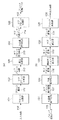
図1(a)は、実施形態における画像符号化装置のブロック構成図、図1(b)は画像復号装置のブロック構成図である。
<First Embodiment>
1 (a) is a block diagram of an image coding apparatus in embodiment 1 (b) is a block diagram of an image decoding apparatus.
画像符号化装置は、ブロック分割部101、サブブロック分割部102、差分算出部103、可変長符号化部104、サブブロック削減部105を有する。また、画像復号装置は、可変長復号化部121、予測復号化部122、削減サブブロック復元部123、サブブロック統合部124、ブロック統合部125を有する。
The image coding apparatus includes a
先ず、画像符号化装置について説明する。 First, an image encoding device will be described.
ブロック分割部101は、符号化対象の画像データを信号線110を介して、複数画素で構成されるブロックを単位に入力し、入力したブロック画像をサブブロック分割部102に出力する。以下、そのブロックの画像データを単にブロック画像、もしくはブロック画像データという。
The
ここで言うブロックのサイズは、その水平、垂直方向のサイズ(画素数)が、後述するサブブロックの整数倍である。本実施形態では、説明を簡単なものとするため、ブロックのサイズを16×16画素とし、サブブロックのサイズを8×8画素として説明する。なお、ブロックのサイズ、サブブロックは、共に正方である必要はない。また、実施形態では、符号化対象の画像データの入力源は、イメージスキャナとするが、非圧縮の画像データを記憶している記憶装置でもよく、その種類は問わない。 As for the size of the block here, the size (number of pixels) in the horizontal and vertical directions is an integral multiple of a sub-block described later. In the present embodiment, in order to simplify the description, the block size is assumed to be 16 × 16 pixels, and the sub-block size is assumed to be 8 × 8 pixels. Note that both the block size and the sub-block need not be square. In the embodiment, the input source of the image data to be encoded is an image scanner, but it may be a storage device storing uncompressed image data, and the type thereof is not limited.
サブブロック分割部102は、入力したブロック画像データを、複数のサブブロックデータに分割し、各サブブロックデータの画像(以下、サブブロック画像、もしくはサブブロック画像データという)を、信号線112を介して差分算出部103に出力する。すなわち、このサブブロック分割部102は、入力したブロック画像から、複数のサブブロックを生成するサブブロック生成部として機能する。このサブブロックのサイズは上記の通り8×8画素としているので、1つのブロック画像から4つのサブブロック画像が生成されることになる。
The sub-block dividing
ここで実施形態におけるサブブロック分割部102の分割処理を例を図2を参照して説明する。
Here, an example of the dividing process of the sub-block dividing
同図では、16×16画素のブロック画像Bから、4つのサブブロックデータSB(0)乃至SB(3)を生成する例を示している。 In the figure, an example is shown in which four sub-block data SB (0) to SB (3) are generated from a block image B of 16 × 16 pixels.
ブロック画像B内を、2×2画素のサイズのウインドウを単位にラスタースキャンし、そのウインドウ内において相対的に同位置の画素により、サブブロックSB(0)乃至SB(3)を生成する。すなわち、2×2画素ウインドウ内の左上位置にある画素をサブブロックSB(0)の画素として抽出する。同様に、2×2画素ウインドウ内の右上位置にある画素をサブブロックSB(1)、左下位置にある画素をサブブロックSB(2)、右下位置にある画素をサブブロックSB(3)の画素として抽出する。なお、サブブロックSB(k)のkは、ブロック画像中の2×2画素ウインドウからサブブロックの画素を決定する際のラスタースキャン順に割り当てた番号であり、以降、サブブロック番号と言う。 The block image B is raster-scanned in units of 2 × 2 pixel size windows, and sub-blocks SB (0) to SB (3) are generated by pixels at the same position in the window. That is, the pixel at the upper left position in the 2 × 2 pixel window is extracted as the pixel of the sub-block SB (0). Similarly, the pixel at the upper right position in the 2 × 2 pixel window is the sub block SB (1), the pixel at the lower left position is the sub block SB (2), and the pixel at the lower right position is the sub block SB (3). Extract as pixels. Note that k of the sub-block SB (k) is a number assigned in the raster scan order when determining the pixels of the sub-block from the 2 × 2 pixel window in the block image, and is hereinafter referred to as a sub-block number.
ブロック画像Bの座標(x,y)の画素値をB(x、y)とし、サブブロックSB(k)(k=0、1、2、3)内の画素値をSB(k、x、y)と定義すると、次の通りである。
SB(0,i,j)=B(2×i,2×j)
SB(1,i,j)=B(2×i+1,2×j)
SB(2,i,j)=B(2×i,2×j+1)
SB(3,i,j)=B(2×i+1,2×j+1)
(但し、i,j=0,1,…,7)
次に差分算出部103の処理を説明する。差分算出部103は、上記のようにしてサブブロック分割部102から出力されたサブブロックSB(0)乃至SB(3)を入力する。そして、差分算出部103は、サブブロックSB(0)については、そのまま可変長符号化部104に出力する。また、差分算出部103は、着目サブブロックSB(k)(k≧1)については、そのサブブロックSB(k)とサブブロックSB(0)の互いに同じ位置にある画素との差分を算出する。1つのサブブロックは8×8画素で構成されるので、その算出した差分データも8×8個存在する。以下、サブブロックSB(k)とSB(0)で算出される8×8個の差分データを、サブブロック差分画像SB’(k)という。差分算出部103が生成する、サブブロック差分画像SB’(1)乃至SB’(3)の算出は次の通りである。
SB’(1)=SB(1,i,j)−SB(0,i,j)
SB’(2)=SB(2,i,j)−SB(0,i,j)
SB’(3)=SB(3,i,j)−SB(0,i,j)
(但し、i,j=0,1,…,7)
The pixel value of the coordinates (x, y) of the block image B is B (x, y), and the pixel values in the sub-block SB (k) (k = 0, 1, 2, 3) are SB (k, x, y) is defined as follows.
SB (0, i, j) = B (2 × i, 2 × j)
SB (1, i, j) = B (2 × i + 1, 2 × j)
SB (2, i, j) = B (2 × i, 2 × j + 1)
SB (3, i, j) = B (2 × i + 1, 2 × j + 1)
(However, i, j = 0,1, ..., 7)
Next, the process of the
SB ′ (1) = SB (1, i, j) −SB (0, i, j)
SB ′ (2) = SB (2, i, j) −SB (0, i, j)
SB ′ (3) = SB (3, i, j) −SB (0, i, j)
(However, i, j = 0,1, ..., 7)
なお、上記の算出結果、SB’(0)の各画素の値は{−255〜+255}の値、すなわち、8ビットを超えるデータで表現しなければならない。そこで、次のようにしても構わない。具体的には、2つのデータZ0、Z1の排他論理和をXOR(Z0、Z1)と表わすとき、
SB’(1)=XOR{SB(1,i,j),SB(0,i,j)}
SB’(2)=XOR{SB(2,i,j),SB(0,i,j)}
SB’(3)=XOR{SB(3,i,j),SB(0,i,j)}
とする。
As a result of the above calculation, the value of each pixel of SB ′ (0) must be represented by a value of {−255 to +255}, that is, data exceeding 8 bits. Therefore, the following may be used. Specifically, when the exclusive OR of two data Z0 and Z1 is expressed as XOR (Z0, Z1),
SB ′ (1) = XOR {SB (1, i, j), SB (0, i, j)}
SB ′ (2) = XOR {SB (2, i, j), SB (0, i, j)}
SB ′ (3) = XOR {SB (3, i, j), SB (0, i, j)}
And
このようにすると、SB(0,i,j)が判っていれば、
SB(1)=XOR{SB’(1,i,j),SB(0,i,j)}
SB(2)=XOR{SB’(2,i,j),SB(0,i,j)}
SB(3)=XOR{SB’(3,i,j),SB(0,i,j)}
とすることで、元のサブブロック画像SB(1)乃至SB(3)を復元できる。
In this way, if SB (0, i, j) is known,
SB (1) = XOR {SB ′ (1, i, j), SB (0, i, j)}
SB (2) = XOR {SB ′ (2, i, j), SB (0, i, j)}
SB (3) = XOR {SB ′ (3, i, j), SB (0, i, j)}
By doing so, the original sub-block images SB (1) to SB (3) can be restored.
図3にサブブロック差分画像の例を示す。同図でブロック画像301は、簡単のため白画素と黒画素の2つの色で表わされる画像である。サブブロック分割すると、図示のサブブロック画像SB(0)乃至SB(3)(図示の符号311乃至314)が生成される。サブブロック画像SB(0)はそのまま可変長符号化部104に出力される。他のサブブロックSB(1)乃至(3)は、サブブロックSB(0)内の画素の値を予測値として差分を算出することで、サブブロック差分画像SB’(1)乃至SB’(3)(図示の符号322乃至324)が生成され、可変長符号化部104に供給される。
FIG. 3 shows an example of the sub-block difference image. In the drawing, a block image 301 is an image represented by two colors of a white pixel and a black pixel for simplicity. When sub-block division is performed, the illustrated sub-block images SB (0) to SB (3) (
各サブブロック内の座標(x、y)の各画素は、オリジナルのブロック画像中の互いに隣接する画素であるから、それらの画素の色は互いに同じ色か、近似する色である確率が高い。図3では極端な例を示しているので、サブブロック差分画像SB’(0)乃至SB’(3)の各画素の値は白(ゼロ)になっている。実際には、サブブロック差分画像SB’(0)乃至SB’(3)の全画素がゼロになることは希であるが、少なくともサブブロックSB(0)と比較すると、それぞれの値は0に近い値になる確率が非常に高くなる。 Since each pixel of coordinates (x, y) in each sub-block is a pixel adjacent to each other in the original block image, there is a high probability that the colors of these pixels are the same color or similar colors. Since FIG. 3 shows an extreme example, the value of each pixel of the sub-block difference images SB ′ (0) to SB ′ (3) is white (zero). Actually, it is rare that all the pixels of the sub-block difference images SB ′ (0) to SB ′ (3) become zero, but each value becomes 0 when compared with at least the sub-block SB (0). The probability of being close is very high.
次に可変長符号化部104について説明する。この可変長符号化部104は、サブブロック画像SB(0)、サブブロック差分画像SB’(1)、SB’(2)、SB’(3)の順番に符号化処理を行ない、その順番に符号化データ(サブブロック符号化データ)をサブブロック削減部105に出力する。
Next, the variable
可変長符号化部104は、可変長符号化として一般的によく使われるランレングス符号化とハフマン符号化を組み合わせた符号化を使う。図4に、この可変長符号化部104における圧縮符号化の例を示す。ランレングス符号化部411は、サブブロック画像SB(0)、サブブロック差分画像SB’(1)、SB’(2)、SB’(3)の順番にランレングス符号化し、ハフマン符号化部412にその符号化データを出力する。サブブロック差分画像SB’(1)、SB’(2)、SB’(3)は図3の例でも示したように、差分値が同じくなる確率が高いので、ランレングス符号化部411によるデータ圧縮の効果がある。ランレングス符号化411は局所的な符号化であるため、データ列全体のパターンを圧縮するために更にハフマン符号化部412によって圧縮符号化を行なう。可変長符号化の結果であるサブブロック圧縮データ421乃至424は、信号線114を介してサブブロック削減部105に供給される。なお、ブロック削減部105には、サブブロック圧縮データ421、422、423、424の順、すなわち、サブブロック画像SB(0)、サブブロック差分画像SB’(1)、SB’(2)、SB’(3)の圧縮データの順番である。
The variable
なお、上記は、符号化の一例を示しているのであって、他の符号化技術を採用してもかまわない。特に、サブブロック画像SB(0)については、同じ画素値が連続する確率が低いと言えるので、そのサブブロック内をラスタースキャンし、予測符号化を行なうようにしても構わない。 The above shows an example of encoding, and other encoding techniques may be adopted. In particular, for the sub-block image SB (0), it can be said that the probability that the same pixel value continues is low, and therefore, the sub-block image may be subjected to the raster scan and the predictive encoding is performed.
サブブロック削減部105は、可変長符号化部104からのサブブロック圧縮データ421乃至424を順に入力し、内部のメモリに格納すると共に、各サブブロックの符号化データ量を求める。そして、1ブロック分の圧縮データ量が、予め設定された1ブロックの最大データサイズ(閾値)以内となるサブブロック圧縮データを、出力対象のサブブロック圧縮データとして決定する。
The
例えば、サブブロック圧縮データ421乃至424の夫々のデータ量をL(0)乃至L(3)、許容符号化データ量を示す閾値をThと表わしたとき、合算関数Σを用いた次式を満たす最大整数iを求める。
ΣL(i)≦Th
For example, when the respective data amounts of the sub-block compressed data 421 to 424 are expressed as L (0) to L (3) and the threshold value indicating the allowable encoded data amount is expressed as Th, the following expression using the summation function Σ is satisfied. Find the maximum integer i.
ΣL (i) ≦ Th
例えば、L(0)+L(1)+L(2)≦Thを満たし、L(0)+L(1)+L(2)+L(3)>Thとなった場合、変数iは“2”となる。従って、サブブロック圧縮データ421乃至423の3つ1ブロック分の圧縮データを構築し、サブブロック圧縮データ424は破棄する。ここで、破棄されるサブブロック圧縮データを、欠落サブブロックデータという。
For example, when L (0) + L (1) + L (2) ≦ Th is satisfied and L (0) + L (1) + L (2) + L (3)> Th, the variable i is “2”. . Therefore, compressed data for one block of the sub-block compressed data 421 to 423 is constructed, and the sub-block
尚、欠落サブブロックデータを決定する順番は、サブブロック番号の降順に決定するものとしたが、復号装置と同じにすれば良いので、上記に限らない。但し、サブブロック番号0のサブブロック圧縮データは、サブブロック差分画像の差分を算出する際の基準となるサブブロックSB(0)の圧縮データであるので、削除対象とはならないようにする。それ故、上記閾値は、これを考慮して決定することが望まれる。
The order of determining the missing sub-block data is determined in descending order of the sub-block numbers. However, the order is not limited to the above because it may be the same as that of the decoding device. However, since the sub-block compressed data of
サブブロック削減部105は、上記のようにして、削除対象外のサブブロック圧縮データを順に並べ、1ブロック分の符号化データを構築し、それを出力する。1ブロックの符号化データを固定長(閾値と同じでよい)にするのであれば、固定長に満たない部分にはEOSB(End Of Sub Block)符号語や予め決められたダミーデータを挿入すればよい。これは固定長で少ない容量のバッファしか用意できないハードウェアで圧縮処理を実装する場合には特に有効である。
The
なお、1ブロック分の符号化データを可変長にするのであれば、1ブロック分の符号化データの先頭にブロックヘッダを付加する。そして、そのブロックヘッダ内に、削除したサブブロック(1つとは限らない)のサブブロック番号の最小値を格納するか、或いは、実在するサブブロック圧縮データのサブブロック番号の最大値を格納すればよい。この場合、削除するための基準としては、符号量ではなく、補間による誤差の絶対値の累積値等の画質評価値を用いることが望ましい。 If the encoded data for one block has a variable length, a block header is added to the head of the encoded data for one block. If the minimum value of the sub-block number of the deleted sub-block (not necessarily one) is stored in the block header, or the maximum value of the sub-block number of the existing sub-block compressed data is stored Good. In this case, it is desirable to use an image quality evaluation value such as a cumulative value of the absolute value of the error due to interpolation, as a criterion for deletion, instead of the code amount.
以上実施形態における画像符号化装置の処理内容を説明した。次に、実施形態における画像復号装置(図1(b)参照)の各処理部の処理内容を以下に説明する。なお、以下では、1ブロックの符号化データが固定長であるものとして説明する。 The processing contents of the image encoding device in the embodiment have been described above. Next, processing contents of each processing unit of the image decoding apparatus (see FIG. 1B) in the embodiment will be described below. In the following description, it is assumed that one block of encoded data has a fixed length.
可変長復号化部121は、図5に示すように、ハフマン復号化部511、ランレングス復号化部512で構成され、ちょうど図4の可変長符号化部104の構成と逆の構成となっている。
As shown in FIG. 5, the variable
可変長復号化部121は、信号線115を介して、1ブロック分の符号化データ(固定長)を入力し、サブブロック画像SB(0)、サブブロック差分画像SB’(1)、SB’(2)、SB’(3)の順番に復号する。このとき、例えば、EOSBを検出した場合には、それまでに復号したサブブロック圧縮データの復号結果と、最後に復号したサブブロック番号を予測復号化部122に信号線131を介して出力する。
The variable
例えば、1ブロック分の符号化データには、図5に示すように、サブブロック画像SB(0)、サブブロック差分画像SB’(1)、SB’(2)の符号化データが格納されているとする。すなわち、サブブロック差分画像SB’(3)の符号化データが存在しなかったとする。この場合には、図5に示すように、それら3つのサブブロック圧縮データから、サブブロック画像SB(0)、サブブロック差分画像SB’(1)、SB’(2)が復号される。 For example, as shown in FIG. 5, the encoded data for one block stores the encoded data of the sub-block image SB (0), the sub-block difference image SB ′ (1), and SB ′ (2). Suppose that That is, it is assumed that there is no encoded data of the sub-block difference image SB ′ (3). In this case, as shown in FIG. 5, the sub-block image SB (0), the sub-block difference images SB '(1), and SB' (2) are decoded from the three sub-block compressed data.
予測復号化部122は、入力したサブブロック画像SB(0)については、そのまま削減サブブロック復元部123に出力する。一方、入力したサブブロック差分画像SB’(k)については、その中の各画素位置の差分値に、サブブロック画像SB(0)の該当する位置の画素値を加算することで、サブブロック画像SB(k)を復元する。
SB(1)=SB’(1,i,j)+SB(0,i,j)
SB(2)=SB’(2,i,j)+SB(0,i,j)
SB(3)=SB’(3,i,j)+SB(0,i,j)
The predictive decoding unit 122 outputs the input sub-block image SB (0) to the reduced
SB (1) = SB ′ (1, i, j) + SB (0, i, j)
SB (2) = SB ′ (2, i, j) + SB (0, i, j)
SB (3) = SB ′ (3, i, j) + SB (0, i, j)
なお、図5の場合、サブブロック差分画像SB’(3)は存在しないので、予測復号化部122は、サブブロック画像SB(3)を生成しない。また、予測復号化部122は復元したサブブロック画像SB(0)乃至SB(2)、及び、復元できた最後のサブブロック番号(図5の場合には“2”)を削減サブブロック復元部123に、信号線132を介して出力する。
In the case of FIG. 5, since the sub-block difference image SB ′ (3) does not exist, the predictive decoding unit 122 does not generate the sub-block image SB (3). Also, the predictive decoding unit 122 reduces the restored sub-block images SB (0) to SB (2) and the last sub-block number that has been restored (“2” in the case of FIG. 5). The signal is output to the
削減サブブロック復元部123は、予測復号化部122から、サブブロック番号“3”、すなわち、全サブブロックの復元ができたとの通知を受信した場合、入力したサブブロック画像SB(0)乃至SB(3)をそのままサブブロック統合部124に出力する。
When receiving a notification from the predictive decoding unit 122 that the subblock number is “3”, that is, all subblocks have been restored, the reduced
一方、削減サブブロック復元部123が、予測復号化部122から、サブブロック番号“3”未満(“2”以下)を示す通知を入力した場合、欠落したサブブロック画像の復元処理を行なう。例えば、図6に示すように、サブブロックSB(0)乃至SB(2)(図示の符号521乃至523)が復元でき、サブブロックSB(3)が欠落しているとする。この場合、サブブロックSB(3)で示される各欠落画素位置の周り8画素(図示の符号621乃至624、626乃至629)は、実在するサブブロック内の画素データである。よって、削減サブブロック復元部123は、その実在するそれらサブブロック内の画素の値から、欠落画素位置625の画素値を、内挿予測(補間)を使って復元する。
On the other hand, when the reduced
なお、図6において、ブロックの下端ライン、及び、右端列の位置にあるサブブロックSB(3)で定義される欠落画素については、その周囲に実在する画素が8つ未満となる。この場合、参照できる実在する画素からその欠落画素の値を算出する。また、欠落画素を挟む2つの実在する画素の値から、その欠落画素の値を算出しても良い。 In FIG. 6, for the missing pixels defined by the sub-block SB (3) at the position of the lower end line of the block and the right end column, there are less than 8 pixels around it. In this case, the value of the missing pixel is calculated from the existing pixels that can be referred to. Alternatively, the value of the missing pixel may be calculated from the values of two existing pixels that sandwich the missing pixel.
また、復元できたサブブロック画像が2つ、すなわち、サブブロック画像SB(0)、SB(1)であった場合、1つの欠落画素の近傍(もしくは周辺)に位置する実在する画素の個数は2乃至3個となるので、その画素を用いて補間演算し、欠落画素の値を算出する。 In addition, when there are two sub-block images that can be restored, that is, the sub-block images SB (0) and SB (1), the number of actual pixels located in the vicinity (or the periphery) of one missing pixel is Since there are two to three, interpolation is performed using the pixels, and the value of the missing pixel is calculated.
そして、復元できたのがサブブロック画像SB(0)のみであった場合には、サブブロック画像SB(0)の画素値から、線形補間演算を行なうことで、残りの3つのサブブロック画像SB(1)乃至SB(3)を復元する。ただし、ブロックの最下ライン、右端列の位置の、サブブロックSB(1)乃至SB(3)で定義される画素位置については、サブブロックSB(0)で示される画素値をそのまま利用するものとする。 If only the sub-block image SB (0) can be restored, linear interpolation is performed from the pixel values of the sub-block image SB (0), thereby remaining three sub-block images SB. (1) to SB (3) are restored. However, for the pixel position defined by the sub-blocks SB (1) to SB (3) at the position of the bottom line and the rightmost column of the block, the pixel value indicated by the sub-block SB (0) is used as it is. And
以上のようにして、圧縮時のサブブロック分割部102によって1ブロックの近傍画素(実施形態では2×2画素)を複数のサブブロックそれぞれに分散させたことで、補間処理に利用できる周囲の画素の個数を十分に確保できる。従って、画素欠落による画質劣化を最小化することができる。
As described above, neighboring pixels (2 × 2 pixels in the embodiment) of one block are distributed to a plurality of subblocks by the
さて、サブブロック統合部124では、上記のようにして復元された4つのサブブロックデータ内の同位置の画素が、オリジナルのブロック内の隣接する2×2画素であるものとして統合処理を行なう。すなわち、サブブロック画像SB(0)乃至SB(3)の各画素を、オリジナルのブロック(16×16画素)に再配置することにより、ブロック画像を生成する。そして、そのブロック画像をブロック統合部125に信号線134を介して出力する。ブロック統合部125は、サブブロック統合部124から入力した16×16画素のブロック画像を、連結し、画像全体に渡って伸張処理された画像を生成し、信号線135を介して出力する。
Now, the
以上実施形態に係る画像符号化装置及びその復号装置の構成とその処理を説明した。本実施形態では、1ブロックのサイズを16×16画素、サブブロックを8×8画素としたが、これによって本発明が限定されるものではない。1ブロックの画像内を、p×q画素(p,qは正の整数であり、少なくとも一方は2以上)のサイズのウインドウを単位にラスタースキャンした場合、p×q個のサブブロックが生成できる。この場合の、各サブブロックSB(0)乃至SB(p×q−1)は次のようになる。但し、以下において、mod(a,b)は整数aを整数bで除算した際の余りを示し、floor(c)は実数cを超えない最大整数を表す関数である。
SB(0,i,j)=B(p×i,q×j)
SB(1,i,j)=B(p×i+1,q×j)
:
SB(s,i,j)=B(p×i+mod(s,p),q×j+floor(s/q))
:
SB(p×q−1,i,j)=B(p×i+mod(p×q-1,p),q×j+floor((p×q-1)/q))
(サブブロックの水平方向の画素数をm、垂直方向の画素数nとしたとき、i,jは0≦i≦m−1、0≦j≦n−1の関係にある)
The configurations and processes of the image encoding device and the decoding device according to the embodiment have been described above. In this embodiment, the size of one block is 16 × 16 pixels and the sub-block is 8 × 8 pixels. However, the present invention is not limited to this. When a raster scan is performed in units of windows of a size of p × q pixels (p and q are positive integers, at least one is 2 or more) in one block image, p × q sub-blocks can be generated. . In this case, each of the sub blocks SB (0) to SB (p × q−1) is as follows. However, in the following, mod (a, b) represents the remainder when the integer a is divided by the integer b, and floor (c) is a function representing the maximum integer not exceeding the real number c.
SB (0, i, j) = B (p × i, q × j)
SB (1, i, j) = B (p × i + 1, q × j)
:
SB (s, i, j) = B (p * i + mod (s, p), q * j + floor (s / q))
:
SB (p × q−1, i, j) = B (p × i + mod (p × q−1, p), q × j + floor ((p × q−1) / q))
(If the number of pixels in the horizontal direction of the sub-block is m and the number of pixels in the vertical direction is n, i and j have a relationship of 0 ≦ i ≦ m−1 and 0 ≦ j ≦ n−1)
また、1つのブロックから2×2個を超えるサブブロックを生成した場合、着目サブブロック画像SB(k)のサブブロック差分画像SB’(k)を生成する際に利用する予測値は、先行するサブブロックの中で着目サブブロックに隣接するサブブロックの画素値とすることが望ましい。理由は、サブブロック(k)を構成する各画素に空間的に距離的に近い画素を持つのは、着目サブブロックに隣接するサブブロックSBであるからである。また、サブブロック差分画像SB’(k)を生成する際には、サブブロック画像SB(k)と着目サブブロックに隣接するサブブロックSB(k―j)(j<k,jは正の整数)とを排他論理和しても構わない。または、先行するサブブロックの中で着目サブブロックに隣接する複数のサブブロックの画素値より内挿予測しても構わない。 In addition, when more than 2 × 2 sub-blocks are generated from one block, the prediction value used when generating the sub-block difference image SB ′ (k) of the target sub-block image SB (k) precedes It is desirable to set the pixel value of a sub block adjacent to the target sub block in the sub block. The reason is that the sub-block SB adjacent to the target sub-block has the pixels spatially close to each pixel constituting the sub-block (k). Further, when generating the sub-block difference image SB ′ (k), the sub-block image SB (k) and the sub-block SB (k−j) adjacent to the target sub-block (j <k, j is a positive integer) ) May be exclusive ORed. Alternatively, interpolation prediction may be performed based on pixel values of a plurality of subblocks adjacent to the target subblock among the preceding subblocks.
また、実施形態では予測復号化における内挿予測を行って欠落画素の値を求める例を示した。一般に画像においては局所的な相関性があるため、圧縮処理時に相関方向検出して検出結果を保存しておき、復号化時に欠落させた画素の復元に相関方向を使って周囲の画素から予測することで復元精度を高めることに利用することも可能である。例えば、可変長符号化部131で垂直方向、水平方向、45°ジグザグ、135°ジグザグのように複数のスキャン方向で符号化するものとする。この場合、符号量が最小となるスキャン方向の相関性が高いので、スキャン方向の符号量から相関方向を判定しても良い。
In the embodiment, an example in which the value of a missing pixel is obtained by performing interpolation prediction in predictive decoding. In general, since there is local correlation in an image, the correlation direction is detected at the time of compression processing and the detection result is stored, and the correlation direction is used to restore the missing pixels at the time of decoding and prediction is performed from surrounding pixels. Therefore, it can be used to increase the restoration accuracy. For example, it is assumed that the variable
また、実施形態ではサブブロック削減部105によって削減されるサブブロック圧縮データはサブブロック番号の固定順(降順)で削除することを示したが、サブブロック圧縮データのうち、符号化データの少ない順に削減するようにしても良い。この場合、削除したサブブロック番号をブロックヘッダに格納し、実在するサブブロック圧縮データは昇順に並んでいるものとして扱えば良いであろう。
In the embodiment, the sub-block compressed data reduced by the
また、特に符号化対象の画像が2値画像の場合、サブブロック内の1の数(予測が外れた画素の数)が所定の閾値より少ないなら、そのサブブロックは高い確率で復元可能なことを意味している。従って、サブブロック内の1の数が少ない順番でサブブロックを削って符号量制御を行っても良い。あるいは、復元した時の誤差が少なくなる順に削減するようにしても良い。特に、複数のサブブロックを削減する場合は、復元順序が復元画質に影響を及ぼすので、重要である。また、上記実施形態では、符号量を基準に削減するサブブロックを決定していたが、画質(復元誤差)を基準に削減するサブブロックを決定してもよい。例えば、上記サブブロック毎に予測値との差分絶対値を累積する手段と具備し、上記累積値が所定値以下となるサブブロックのデータを伝送しないようにしても良い。 In particular, when the image to be encoded is a binary image, if the number of 1s in the sub-block (the number of pixels that are not predicted) is less than a predetermined threshold, the sub-block can be restored with high probability. Means. Therefore, the code amount control may be performed by cutting the sub-blocks in the order of decreasing number of 1s in the sub-blocks. Or you may make it reduce in order with a small error at the time of decompression | restoration. In particular, when a plurality of sub-blocks are reduced, the restoration order affects the restoration image quality, which is important. In the above embodiment, the subblock to be reduced is determined based on the code amount. However, the subblock to be reduced may be determined based on the image quality (restoration error). For example, it may be provided with means for accumulating the absolute value of the difference from the predicted value for each sub-block so that the data of the sub-block whose accumulated value is not more than a predetermined value is not transmitted.
<第2の実施形態>
図7(a)は、第2の実施形態における画像符号化装置のブロック構成図を示し、図7(b)は画像復号装置のブロック構成図を示している。本第2の実施形態での画像符号化装置及び画像復号装置は、以下の説明から明らかになるが、文字線画に特に適したものである。
<Second Embodiment>
FIG. 7A shows a block configuration diagram of the image encoding device in the second embodiment, and FIG. 7B shows a block configuration diagram of the image decoding device. The image encoding device and the image decoding device according to the second embodiment will be apparent from the following description, but are particularly suitable for character line drawings.
第2の実施形態における画像符号化装置は、ブロック化部701、2色抽出部702、識別情報生成部703、符号化部704、及び、パック部705を有する。また、画像復号装置は、アンパック部711、レジスタ712、713、セレクタ715、ラスター化部716を有する。なお、各処理部間には、同期をとるためのバッファメモリが介在するが、図では示していない。
The image encoding apparatus according to the second embodiment includes a
先ず、第2の実施形態における画像符号化装置について説明する。説明を簡単なものとするため、ここでも、1ブロックのサイズを16×16画素とするが、1ブロックは複数の画素で構成され、且つ、後述するサブブロックの水平、垂直方向の画素数の整数倍であれば良い。また、画像は1色成分(モノクロ画像)で1画素が8ビットで表わされるものとして説明する。 First, an image encoding device according to the second embodiment will be described. In order to simplify the description, the size of one block is also 16 × 16 pixels here, but one block is composed of a plurality of pixels, and the number of pixels in the horizontal and vertical directions of a sub-block described later is set. Any integer multiple is sufficient. Further, the image will be described as one color component (monochrome image) and one pixel is represented by 8 bits.
ブロック化部701は、符号化対象の画像データから、1ブロック(=16×16画素)を単位に入力し、2色抽出部702、識別情報生成部703に出力する。以下、この1ブロック分の画像を第1の実施形態と同様にブロック画像という。
The blocking
2色検出部702は、入力したブロック画像中から2つの代表色C1、C2を抽出する。具体的には、2色抽出部702は、ブロック内の各画素の値の平均値AVEを算出する。そして、算出した平均値AVE以下の画素値を持つ画素群(第1グループ)と、平均値よりも大きな画素値を持つ画素群(第2グループ)に分類する。そして、2色抽出部702は、第1グループに属する各画素の平均値を算出し、それを代表色C1として決定する。また、同様に、2色抽出部102は、第2グループに属する各画素の平均値を算出し、それを代表色C2として決定する。そして、2色抽出部702は、決定した代表色C1、C2をパック部705に出力するとともに、平均値AVEを識別情報生成部703に出力する。
The two-
なお、C2とC1の差D(=C2−C1)が、予め設定された閾値以下であった場合、特に、着目ブロック内の全画素が同じ色であった場合(C2=C1の場合に相当する)には、C1、C2の両方をAVEとする。これにより、識別情報を削除することも可能である。即ち、復号時にC1とC2を比較し、C2=C1の場合はブロック内の各画素値をC1(C2)に全て置き換えるのである。 Note that when the difference D (= C2−C1) between C2 and C1 is equal to or smaller than a preset threshold, particularly when all pixels in the block of interest have the same color (corresponding to the case of C2 = C1). ), Both C1 and C2 are set to AVE. Thereby, it is also possible to delete the identification information. That is, C1 and C2 are compared at the time of decoding. When C2 = C1, all pixel values in the block are replaced with C1 (C2).
識別情報生成部703は、着目ブロック画像をラスタースキャンし、その際に2色抽出部702からの平均値AVEと比較し、平均値AVE以下の画素を“0”、その平均値AVEを超える画素を“1”とする2値(1ビット)の情報を生成する。そして、その生成した情報を符号化部704に出力する。要するに、この情報は、着目ブロックの各画素が、先に示した第1グループに属する画素であるか、第2グループに属する画素であるかを識別するための情報と言える。それ故、以下では、この情報を識別情報という。第2の実施形態では、1ブロックのサイズが16×16画素としているので、1ブロック分の識別情報は16×16ビットで構成されることになる。
The identification
符号化部704は、上記の識別情報生成部703からの16×16ビットの識別情報を、第1の実施形態と同様のアルゴリムに従って複数(4つ)のサブブロックに分割し、それぞれを符号化する。この符号化部704における詳細は後述する。
The
パック部705は、代表色C1、C2と、符号化部704で符号化された識別情報を結合し、1ブロックの符号化データとして出力する。
The
ここで、本第2の実施形態における符号化部704の詳細を図8に示し、以下に説明する。
Details of the
符号化部704は、図8に示すように、サブブロック分割部811、差分算出部821a乃至821c、可変長符号化部831a乃至831d、符号量検知部851、符号量比較部861、及び、セレクタ841を有する。
As shown in FIG. 8, the
サブブロック分割部811は、入力した16×16個の識別情報(2値データ)を、ちょうど第1の実施形態におけるサブブロック分割部102と同様に、4つのサブブロックに分割する。第1の実施形態では、ブロック、及びサブブロックは画像データを示し、第2の実施形態でのブロック、サブブロックは2値の識別情報を示す点で異なるが、本第2の実施形態におけるブロックと各サブブロックの識別情報の関係は図2と同じである。それ故、本第2の実施形態でも、各サブブロックをそのサブブロック番号kによってSB(k)として表現する。第1の実施形態と同様、16×16ビットの識別情報中の座標(x,y)の識別情報をB(x、y)とし、サブブロックSB(k)(k=0、1、2、3)内の識別情報をSB(k、x、y)と定義すると、次の通りである。
SB(0,i,j)=B(2×i,2×j)
SB(1,i,j)=B(2×i+1,2×j)
SB(2,i,j)=B(2×i,2×j+1)
SB(3,i,j)=B(2×i+1,2×j+1)
The
SB (0, i, j) = B (2 × i, 2 × j)
SB (1, i, j) = B (2 × i + 1, 2 × j)
SB (2, i, j) = B (2 × i, 2 × j + 1)
SB (3, i, j) = B (2 × i + 1, 2 × j + 1)
サブブロック分割部811は、サブブロックSB(0)については、差分算出部821a821a乃至821c、及び、可変長符号化部831dに出力する。そして、サブブロック分割部811は、サブブロックSB(1)を差分算出部821aに、サブブロックSB(2)を差分算出部821bに、そして、サブブロックSB(3)を差分算出部821cに出力する。
The
差分算出部821a乃至821cは、サブブロック差分情報SB’(1)乃至SB’(3)をそれぞれ次式に従って算出する。
SB’(1)=SB(1,i,j)−SB(0,i,j)
SB’(2)=SB(2,i,j)−SB(0,i,j)
SB’(3)=SB(3,i,j)−SB(0,i,j)
The
SB ′ (1) = SB (1, i, j) −SB (0, i, j)
SB ′ (2) = SB (2, i, j) −SB (0, i, j)
SB ′ (3) = SB (3, i, j) −SB (0, i, j)
なお、上記の算出結果、SB’(0)の各画素位置の識別情報の差分値は{−1、0、+1}の値を取り得るが、2値とすることも可能である。具体的には、2つの1ビットのデータZ0、Z1の排他論理和をXOR(Z0、Z1)と表わすとき、次のようにしてサブブロック差分情報SB’()を求めれば良い。
SB’(1)=XOR{SB(1,i,j),SB(0,i,j)}
SB’(2)=XOR{SB(2,i,j),SB(0,i,j)}
SB’(3)=XOR{SB(3,i,j)−SB(0,i,j)}
As a result of the above calculation, the difference value of the identification information of each pixel position of SB ′ (0) can take a value of {−1, 0, +1}, but it can also be a binary value. Specifically, when the exclusive OR of the two 1-bit data Z0 and Z1 is expressed as XOR (Z0, Z1), the sub-block difference information SB ′ () may be obtained as follows.
SB ′ (1) = XOR {SB (1, i, j), SB (0, i, j)}
SB ′ (2) = XOR {SB (2, i, j), SB (0, i, j)}
SB ′ (3) = XOR {SB (3, i, j) −SB (0, i, j)}
可変長符号化部831a乃至831dは、サブブロック差分情報SB’(1)、SB’(2)、SB’(3)及びサブブロック情報SB(0)をそれぞれ可変長符号化を行ない、そのサブブロック圧縮データをセレクタ841、符号量検知部851に出力する。
The variable-length coding units 831a to 831d perform variable-length coding on the sub-block difference information SB ′ (1), SB ′ (2), SB ′ (3) and the sub-block information SB (0), respectively. The block compressed data is output to the
ここで、可変長符号化部831dで生成される符号化データはサブブロック番号“0”のサブブロック情報SB(0)の符号化データであるので、その符号化データのデータ量をL(0)と表わす。また、可変長符号化部831a乃至831cで生成される符号化データはサブブロック差分情報SB’(1)乃至SB’(3)の符号化データを示すので、それぞれの符号化データ量を、サブブロック番号に従ってL(1)乃至L(3)と表わす。 Here, since the encoded data generated by the variable length encoding unit 831d is the encoded data of the sub-block information SB (0) of the sub-block number “0”, the data amount of the encoded data is expressed as L (0 ). In addition, since the encoded data generated by the variable length encoding units 831a to 831c indicates the encoded data of the sub-block difference information SB ′ (1) to SB ′ (3), the amount of each encoded data is set to L (1) to L (3) are represented according to the block number.
符号量検知部851は、上記のL(0)乃至L(3)を検出し、その検出結果を符号量比較部861に出力することになる。
The code
符号量比較部861は、予め設定された閾値Thを用いて、次式を満たす変数iの最大値を求め、その結果をセレクタ841に出力する。
ΣL(i)≦Th
The code
ΣL (i) ≦ Th
例えば、L(0)+L(1)+L(2)≦Thを満たし、L(0)+L(1)+L(2)+L(3)>Thとなった場合、変数iは“2”となるので、“2”を示す信号をセレクタ841に出力する。
For example, when L (0) + L (1) + L (2) ≦ Th is satisfied and L (0) + L (1) + L (2) + L (3)> Th, the variable i is “2”. Therefore, a signal indicating “2” is output to the
セレクタ841は、可変長符号化部831d、831a、831b、831cで生成された4つの符号化データから、符号量比較部861から入力した信号に従った個数の符号化データを入力し、出力する。例えば、符号量比較部861から入力した信号が“2”であった場合には、可変長符号化部831d、831a、831bからの符号化データを、その順番に結合し、固定長とするため不足部のダミービットを付加して、出力する。また、上記の場合には、可変長符号化部831cからの符号化データは破棄する。
The
以上実施形態における画像符号化装置について説明した。次に、実施形態における画像復号装置(図7(b)参照)について説明する。 The image encoding device in the embodiment has been described above. Next, an image decoding apparatus (see FIG. 7B) in the embodiment will be described.
アンパック部711は、入力した1ブロック分の符号化データから、代表色C1、C2及び符号化された識別情報を分離し、代表色C1はレジスタ712に、代表色C2はレジスタ713に、符号化された識別情報を復号部714に出力する。復号部714の詳細は後述するが、入力した識別情報を復号し、16×16個の2値の識別情報を生成し、ラスタースキャン順にセレクタ715に出力する。
The
セレクタ715は、復号部714からの識別情報が“0”の場合にはレジスタ712に格納された代表色C1を選択し、ラスター化部716に出力する。また、セレクタ715は、復号部714からの識別情報が“1”の場合にはレジスタ713に格納された代表色C2を選択し、ラスター化部716に出力する。この処理を1ブロックの復号過程で、16×16回行なうことで、16×16画素で構成されるブロック画像がラスター化部716に出力されることになる。ラスター化部716は、内部にバッファメモリを有し、少なくとも、復元対象の水平方向画素分の画像データが格納される度に、ラスタースキャン順に画素データを出力する。
When the identification information from the
次に、復号部714について図9を使い説明する。図9は本第2の実施形態における復号部714のブロック構成図である。
Next, the
この復号部714は、可変長復号化部911a乃至911d、予測復号化部921a乃至921c、補間部931、及び、サブブロック統合部941を有する。
The
可変長復号化部911a乃至911dは、図8における可変長符号化部831a乃至831dと対をなすものであり、これらによってサブブロック差分情報SB’(1)乃至SB’(3)、及び、サブブロック情報SB(0)を復号する。復号部714は、アンパック部711から、サブブロック番号順に、各サブブロックの圧縮データを入力し、それを可変長復号化部911d、911a、911b、911cの順番に割振る。従って、仮に入力した1ブロック分の符号化データ内に、3つのサブブロックの符号化データしか存在しなかった場合、可変長復号部911cには、符号化データが供給されない。
The variable-
各可変長復号化部911a乃至911dは、それぞれが復号処理を行なう。そして、可変長復号化部911dは、復号したサブブロック情報SB(0)を、予測復号化部921a乃至921c、及び、補間部931に出力する。また、他の可変長復号化部911a乃至911cは、復号して得られたサブブロック差分情報SB’(1)乃至SB’(3)を、対応する予測復号化部921a乃至921cに出力する。ただし、復号すべき符号化データを入力しなかった可変長復号部は、復号できなかったことを示す信号を対応する予測復号化部に出力する。
Each of the variable
予測復号化部921aは、予測値としてサブブロック情報SB(0)を入力し、それとサブブロック差分情報SB’(1)を加算することで、サブブロック情報SB(1)を復元する。他の予測復号化部921b、921cも同様の処理を行ない、サブブロック情報SB(2)、SB(3)を復元する。ただし、該当する可変長復号化部から復号できない旨の信号を入力した予測復号化部は、該当するサブブロックSB()が存在しないことを補間部931に出力する。
The
補間部931は、上記のようにしてサブブロック情報SB()を入力するが、4つのサブブロック情報の入力がなかった場合には、欠落したサブブロック情報を、実在するサブブロック情報に基づき補間する。例えば、サブブロックSB(3)が欠落していた場合には、その欠落したサブブロックSB(3)内の各画素位置の識別情報を、その近傍の実在する識別情報に基づき補間する。簡単には、欠落位置の周りの実在する近傍の位置情報の個数がN個であり、そのうち過半数が“1”である場合には欠落位置の識別情報を“1”し、“1”の個数が過半数に満たない場合には“0”とする。
The interpolating
一般に文字線画の画像の場合、文字線画を構成する黒画素が連続するから、上記のようにして補間することで、高い確率で欠落した差分情報を復元できる。 In general, in the case of an image of a character line drawing, black pixels constituting the character line drawing are continuous. Therefore, by interpolating as described above, it is possible to restore the difference information that has been lost with a high probability.
以上本発明に係る実施形態を説明したが、本実施形態で示した各装置が有する処理部の機能、及び、その全体の処理シーケンスを、パーソナルコンピュータ等の汎用情報処理装置で実行するコンピュータプログラムでもって実現しても構わない。例えば、図1(a)に示す符号化装置の場合、各処理部101乃至105は、コンピュータプログラムにおけるサブルーチンもしくは関数として処理を行ない、これを符号化対象の画像に含まれるブロック数だけ繰り返す処理を行なえばよい。
Although the embodiment according to the present invention has been described above, the function of the processing unit included in each apparatus shown in the present embodiment and the entire processing sequence are executed by a general-purpose information processing apparatus such as a personal computer. It may be realized. For example, in the case of the encoding apparatus shown in FIG. 1A, each of the
また、通常コンピュータプログラムは、CD−ROM等のコンピュータ可読記憶媒体に記憶されており、それを読取り装置(CD−ROMドライブ等)にセットし、システムにコピーもしくはインストールすることで実行可能になる。従って、かかるコンピュータ可読記憶媒体も、当然ながら本発明の範疇に入る。 Further, the computer program is usually stored in a computer-readable storage medium such as a CD-ROM, and can be executed by setting it in a reader (CD-ROM drive or the like) and copying or installing it in the system. Accordingly, such a computer readable storage medium is also within the scope of the present invention.
Claims (7)
水平及び垂直方向に複数の画素で構成されるサイズのブロックを単位に、画像データを入力する入力手段と、
前記入力手段で入力した着目ブロックについて、p×q画素(p,qは正の整数であり、少なくとも一方は2以上)のサイズのウインドウを単位とし、各ウインドウ内の相対的に同じ位置の画素データで構成されるサブブロックを生成することにより、p×q個のサブブロックを取得する生成手段と、
前記p×q個のサブブロックを符号化する符号化手段とを備え、
前記符号化手段は、前記p×q個のサブブロックの符号化データの総符号量が予め設定された許容符号化データ量を超えた場合、当該許容符号化データ量以内とするために一部のサブブロックの符号化データを破棄することにより、前記入力手段で入力した着目ブロックの符号化データを生成することを特徴とする画像符号化装置。 An image encoding device for compressing and encoding image data,
Input means for inputting image data in units of blocks of a size composed of a plurality of pixels in the horizontal and vertical directions;
With respect to the block of interest input by the input means, a pixel having a size of p × q pixels (p and q are positive integers, at least one of which is 2 or more) is used as a unit, and pixels at the relatively same position in each window Generating means for obtaining p × q sub-blocks by generating sub-blocks composed of data;
Encoding means for encoding the p × q sub-blocks ,
The encoding means, when the total code amount of the encoded data of the p × q sub-blocks exceeds a preset allowable encoded data amount, is partly set to be within the allowable encoded data amount The encoded data of the block of interest input by the input means is generated by discarding the encoded data of the sub-block .
水平及び垂直方向に複数の画素で構成されるサイズのブロックを単位に、画像データを入力する入力手段と、
前記入力手段で入力した着目ブロックについて、p×q画素(p,qは正の整数であり、少なくとも一方は2以上)のサイズのウインドウを単位とし、各ウインドウ内の相対的に同じ位置の画素データで構成されるサブブロックを生成することにより、p×q個のサブブロックを取得する生成手段と、
前記p×q個のサブブロックを符号化する符号化手段と、
前記p×q個のサブブロックそれぞれの符号化データのデータ量をL(0)乃至L(p×q−1)、予め設定された許容符号化データ量をThとしたとき、
ΣL(i)≦Th
を満たす最大の整数iを求め、当該iで示される個数に相当する前記p×q個のサブブロックの符号化データを、前記入力手段で入力した着目ブロックの符号化データとして出力する出力手段と
を備えることを特徴とする画像符号化装置。 An image encoding device for compressing and encoding image data,
Input means for inputting image data in units of blocks of a size composed of a plurality of pixels in the horizontal and vertical directions;
With respect to the block of interest input by the input means, a pixel having a size of p × q pixels (p and q are positive integers, at least one of which is 2 or more) is used as a unit, and pixels at the relatively same position in each window Generating means for obtaining p × q sub-blocks by generating sub-blocks composed of data;
Encoding means for encoding the p × q sub-blocks;
When the data amount of the encoded data of each of the p × q sub-blocks is L (0) to L (p × q−1) and the preset allowable encoded data amount is Th,
ΣL (i) ≦ Th
Output means for obtaining the maximum integer i satisfying the above and outputting the encoded data of the p × q sub-blocks corresponding to the number indicated by i as the encoded data of the block of interest input by the input means; picture coding device, characterized in that it comprises a.
前記p×q個のサブブロックをSB(0)、SB(1)、…、SB(p×q−1)と定義したとき、
先頭のサブブロックSB(0)はそのサブブロック内の画素値のまま符号化し、
着目サブブロックSB(k)(kは正の整数)を符号化する際には、着目サブブロックSB(k)内の各位置の画素値と、先行するサブブロックSB(k−j)(jは正の整数)内の相対的に同じ位置の画素値との差分を算出することで、サブブロック差分情報SB’(k)を生成し、生成したサブブロック差分情報SB’(k)の各画素位置の差分値を符号化する
ことを特徴とする請求項2に記載の画像符号化装置。 The encoding means includes
When the p × q sub-blocks are defined as SB (0), SB (1),... SB (p × q−1),
The first sub-block SB (0) is encoded with the pixel value in the sub-block,
When encoding the target sub-block SB (k) (k is a positive integer), the pixel value at each position in the target sub-block SB (k) and the preceding sub-block SB (k−j) (j Sub-block difference information SB ′ (k) is generated by calculating a difference with a pixel value at a relatively same position in each of the sub-block difference information SB ′ (k). The image encoding apparatus according to claim 2 , wherein a difference value between pixel positions is encoded.
入力手段が、水平及び垂直方向に複数の画素で構成されるサイズのブロックを単位に、画像データを入力する入力工程と、
生成手段が、前記入力工程で入力した着目ブロックについて、p×q画素(p,qは正の整数であり、少なくとも一方は2以上)のサイズのウインドウを単位とし、各ウインドウ内の相対的に同じ位置の画素データで構成されるサブブロックを生成することにより、p×q個のサブブロックを取得する生成工程と、
符号化手段が、前記p×q個のサブブロックを符号化する符号化工程とを備え、
前記符号化工程では、前記p×q個のサブブロックの符号化データの総符号量が予め設定された許容符号化データ量を超えた場合、当該許容符号化データ量以内とするために一部のサブブロックの符号化データを破棄することにより、前記入力手段で入力した着目ブロックの符号化データを生成することを特徴とする画像符号化装置の制御方法。 A control method of an image encoding device for compressing and encoding image data,
An input step in which the input means inputs image data in units of blocks of a size composed of a plurality of pixels in the horizontal and vertical directions;
With respect to the block of interest input by the generation unit in the input step, a window having a size of p × q pixels (p and q are positive integers, at least one of which is 2 or more) is used as a unit. A generation step of acquiring p × q sub-blocks by generating sub-blocks composed of pixel data at the same position;
Encoding means comprising: an encoding step of encoding the p × q sub-blocks ;
In the encoding step, when the total code amount of the encoded data of the p × q sub-blocks exceeds a preset allowable encoded data amount, a part of the encoded data is set within the allowable encoded data amount. A method for controlling an image encoding device , wherein the encoded data of the block of interest input by the input means is generated by discarding the encoded data of the sub-block .
入力手段が、水平及び垂直方向に複数の画素で構成されるサイズのブロックを単位に、画像データを入力する入力工程と、
生成手段が、前記入力工程で入力した着目ブロックについて、p×q画素(p,qは正の整数であり、少なくとも一方は2以上)のサイズのウインドウを単位とし、各ウインドウ内の相対的に同じ位置の画素データで構成されるサブブロックを生成することにより、p×q個のサブブロックを取得する生成工程と、
符号化手段が、前記p×q個のサブブロックを符号化する符号化工程と、
出力手段が、
前記p×q個のサブブロックそれぞれの符号化データのデータ量をL(0)乃至L(p×q−1)、予め設定された許容符号化データ量をThとしたとき、
ΣL(i)≦Th
を満たす最大の整数iを求め、当該iで示される個数に相当する前記p×q個のサブブロックの符号化データを、前記入力工程で入力した着目ブロックの符号化データとして出力する出力工程と
を備えることを特徴とする画像符号化装置の制御方法。 A control method of an image encoding device for compressing and encoding image data,
An input step in which the input means inputs image data in units of blocks of a size composed of a plurality of pixels in the horizontal and vertical directions;
With respect to the block of interest input by the generation unit in the input step, a window having a size of p × q pixels (p and q are positive integers, at least one of which is 2 or more) is used as a unit. A generation step of acquiring p × q sub-blocks by generating sub-blocks composed of pixel data at the same position;
An encoding step in which encoding means encodes the p × q sub-blocks;
The output means is
When the data amount of the encoded data of each of the p × q sub-blocks is L (0) to L (p × q−1) and the preset allowable encoded data amount is Th,
ΣL (i) ≦ Th
An output step of obtaining the maximum integer i satisfying the above and outputting the encoded data of the p × q sub-blocks corresponding to the number indicated by i as the encoded data of the block of interest input in the input step; control method for picture coding device, characterized in that it comprises a.
Priority Applications (2)
| Application Number | Priority Date | Filing Date | Title |
|---|---|---|---|
| JP2007244444A JP5101962B2 (en) | 2007-09-20 | 2007-09-20 | Image coding apparatus, control method therefor, and computer program |
| US12/211,886 US8238437B2 (en) | 2007-09-20 | 2008-09-17 | Image encoding apparatus, image decoding apparatus, and control method therefor |
Applications Claiming Priority (1)
| Application Number | Priority Date | Filing Date | Title |
|---|---|---|---|
| JP2007244444A JP5101962B2 (en) | 2007-09-20 | 2007-09-20 | Image coding apparatus, control method therefor, and computer program |
Publications (3)
| Publication Number | Publication Date |
|---|---|
| JP2009077176A JP2009077176A (en) | 2009-04-09 |
| JP2009077176A5 JP2009077176A5 (en) | 2010-10-14 |
| JP5101962B2 true JP5101962B2 (en) | 2012-12-19 |
Family
ID=40611729
Family Applications (1)
| Application Number | Title | Priority Date | Filing Date |
|---|---|---|---|
| JP2007244444A Expired - Fee Related JP5101962B2 (en) | 2007-09-20 | 2007-09-20 | Image coding apparatus, control method therefor, and computer program |
Country Status (1)
| Country | Link |
|---|---|
| JP (1) | JP5101962B2 (en) |
Families Citing this family (6)
| Publication number | Priority date | Publication date | Assignee | Title |
|---|---|---|---|---|
| EP2268030A1 (en) * | 2009-06-22 | 2010-12-29 | Thomson Licensing | Image coding with texture refinement using representative patches |
| JP5538985B2 (en) * | 2010-04-13 | 2014-07-02 | キヤノン株式会社 | Image coding apparatus and control method thereof |
| JP5706264B2 (en) | 2011-08-01 | 2015-04-22 | 日本電信電話株式会社 | Image encoding method, image decoding method, image encoding device, image decoding device, image encoding program, and image decoding program |
| JP5653328B2 (en) | 2011-09-26 | 2015-01-14 | 株式会社東芝 | Image processing apparatus and image processing system |
| GB2619685A (en) * | 2021-03-11 | 2023-12-13 | Cryoport Inc | Box-in-a-box shipper |
| CN117240409B (en) * | 2023-11-15 | 2024-01-16 | 深圳市阿龙电子有限公司 | Data processing method for smart phone and smart wearable device |
Family Cites Families (5)
| Publication number | Priority date | Publication date | Assignee | Title |
|---|---|---|---|---|
| JP2930301B2 (en) * | 1988-03-22 | 1999-08-03 | ソニー株式会社 | Data transmission method |
| JP2841453B2 (en) * | 1989-04-14 | 1998-12-24 | ソニー株式会社 | Image transmitting apparatus, image transmitting method, image decoding apparatus, and image receiving method |
| JP2000253403A (en) * | 1999-02-25 | 2000-09-14 | Mitsubishi Electric Corp | Image encoding method converter and image communication system |
| JP3955909B2 (en) * | 2004-09-10 | 2007-08-08 | 国立大学法人九州工業大学 | Image signal processing apparatus and method |
| JP3955910B2 (en) * | 2006-12-04 | 2007-08-08 | 国立大学法人九州工業大学 | Image signal processing method |
-
2007
- 2007-09-20 JP JP2007244444A patent/JP5101962B2/en not_active Expired - Fee Related
Also Published As
| Publication number | Publication date |
|---|---|
| JP2009077176A (en) | 2009-04-09 |
Similar Documents
| Publication | Publication Date | Title |
|---|---|---|
| JP4418762B2 (en) | Image encoding apparatus, image decoding apparatus, control method thereof, computer program, and computer-readable storage medium | |
| US8238437B2 (en) | Image encoding apparatus, image decoding apparatus, and control method therefor | |
| US8213727B2 (en) | Image encoding apparatus and image decoding apparatus, and control method thereof | |
| US7689048B2 (en) | Image encoding apparatus, method, and computer-readable storage medium for encoding a pixel value | |
| US7650039B2 (en) | Image encoding apparatus, image decoding apparatus, control method therefor, computer program, and computer-readable storage medium | |
| JP5101962B2 (en) | Image coding apparatus, control method therefor, and computer program | |
| JP2008017115A (en) | Data compression apparatus and data compression program | |
| JP4956304B2 (en) | Image encoding apparatus, control method therefor, computer program, and computer-readable storage medium | |
| US8031954B2 (en) | Image encoding apparatus and control method thereof using prediction encoding and pixel classification | |
| US7561744B2 (en) | Image encoding apparatus, image decoding apparatus, and their control method, and computer program and computer-readable storage medium | |
| US8041135B2 (en) | Image encoding apparatus and control method thereof | |
| JP2006180456A (en) | Image compressor, image decoder, image converter and image processing method | |
| JP5173867B2 (en) | Image encoding apparatus, image decoding apparatus, and control method thereof | |
| JP6502739B2 (en) | Image coding apparatus, image processing apparatus, image coding method | |
| JP4871822B2 (en) | Image coding apparatus and control method thereof | |
| CN110024383B (en) | Image compression technique | |
| JP5086777B2 (en) | Image encoding apparatus, control method therefor, computer program, and computer-readable storage medium | |
| WO2000018133A1 (en) | Encoding device and method, and decoding device and method | |
| JP4971881B2 (en) | Image encoding apparatus, image decoding apparatus, and control method thereof | |
| JP2009260747A (en) | Image encoding device, and control method thereof | |
| JP4743884B2 (en) | Image coding apparatus and control method thereof | |
| JP4699307B2 (en) | Data compression apparatus and data compression program | |
| JP4131970B2 (en) | Data compression apparatus and data compression program | |
| JP4131969B2 (en) | Data compression apparatus and data compression program | |
| JP2008109195A (en) | Image processor |
Legal Events
| Date | Code | Title | Description |
|---|---|---|---|
| A521 | Written amendment |
Free format text: JAPANESE INTERMEDIATE CODE: A523 Effective date: 20100827 |
|
| A621 | Written request for application examination |
Free format text: JAPANESE INTERMEDIATE CODE: A621 Effective date: 20100827 |
|
| A977 | Report on retrieval |
Free format text: JAPANESE INTERMEDIATE CODE: A971007 Effective date: 20111013 |
|
| A131 | Notification of reasons for refusal |
Free format text: JAPANESE INTERMEDIATE CODE: A131 Effective date: 20111021 |
|
| A521 | Written amendment |
Free format text: JAPANESE INTERMEDIATE CODE: A523 Effective date: 20111215 |
|
| TRDD | Decision of grant or rejection written | ||
| A01 | Written decision to grant a patent or to grant a registration (utility model) |
Free format text: JAPANESE INTERMEDIATE CODE: A01 Effective date: 20120831 |
|
| A01 | Written decision to grant a patent or to grant a registration (utility model) |
Free format text: JAPANESE INTERMEDIATE CODE: A01 |
|
| A61 | First payment of annual fees (during grant procedure) |
Free format text: JAPANESE INTERMEDIATE CODE: A61 Effective date: 20120927 |
|
| FPAY | Renewal fee payment (event date is renewal date of database) |
Free format text: PAYMENT UNTIL: 20151005 Year of fee payment: 3 |
|
| R151 | Written notification of patent or utility model registration |
Ref document number: 5101962 Country of ref document: JP Free format text: JAPANESE INTERMEDIATE CODE: R151 |
|
| FPAY | Renewal fee payment (event date is renewal date of database) |
Free format text: PAYMENT UNTIL: 20151005 Year of fee payment: 3 |
|
| LAPS | Cancellation because of no payment of annual fees |