JP5100101B2 - Image forming apparatus - Google Patents
Image forming apparatus Download PDFInfo
- Publication number
- JP5100101B2 JP5100101B2 JP2006334601A JP2006334601A JP5100101B2 JP 5100101 B2 JP5100101 B2 JP 5100101B2 JP 2006334601 A JP2006334601 A JP 2006334601A JP 2006334601 A JP2006334601 A JP 2006334601A JP 5100101 B2 JP5100101 B2 JP 5100101B2
- Authority
- JP
- Japan
- Prior art keywords
- toner
- transfer
- image
- image forming
- primary transfer
- Prior art date
- Legal status (The legal status is an assumption and is not a legal conclusion. Google has not performed a legal analysis and makes no representation as to the accuracy of the status listed.)
- Active
Links
- 238000012546 transfer Methods 0.000 claims description 544
- 238000011144 upstream manufacturing Methods 0.000 claims description 5
- 239000000463 material Substances 0.000 description 63
- 238000000034 method Methods 0.000 description 20
- 238000010586 diagram Methods 0.000 description 19
- 230000008569 process Effects 0.000 description 16
- 239000003086 colorant Substances 0.000 description 12
- 230000003287 optical effect Effects 0.000 description 11
- 230000015572 biosynthetic process Effects 0.000 description 9
- 238000004140 cleaning Methods 0.000 description 8
- 230000005684 electric field Effects 0.000 description 8
- 230000007246 mechanism Effects 0.000 description 8
- 238000000926 separation method Methods 0.000 description 8
- 238000011161 development Methods 0.000 description 6
- 230000007423 decrease Effects 0.000 description 5
- 230000000694 effects Effects 0.000 description 4
- 229920001971 elastomer Polymers 0.000 description 4
- 239000002245 particle Substances 0.000 description 4
- 239000005060 rubber Substances 0.000 description 4
- 230000006872 improvement Effects 0.000 description 3
- 230000001678 irradiating effect Effects 0.000 description 3
- 238000005096 rolling process Methods 0.000 description 3
- OKTJSMMVPCPJKN-UHFFFAOYSA-N Carbon Chemical compound [C] OKTJSMMVPCPJKN-UHFFFAOYSA-N 0.000 description 2
- JOYRKODLDBILNP-UHFFFAOYSA-N Ethyl urethane Chemical compound CCOC(N)=O JOYRKODLDBILNP-UHFFFAOYSA-N 0.000 description 2
- 230000002411 adverse Effects 0.000 description 2
- 229910052799 carbon Inorganic materials 0.000 description 2
- 230000008859 change Effects 0.000 description 2
- 238000007599 discharging Methods 0.000 description 2
- 239000000049 pigment Substances 0.000 description 2
- -1 polyethylene terephthalate Polymers 0.000 description 2
- 229920006254 polymer film Polymers 0.000 description 2
- 230000009467 reduction Effects 0.000 description 2
- 229920002379 silicone rubber Polymers 0.000 description 2
- 239000007787 solid Substances 0.000 description 2
- 239000002699 waste material Substances 0.000 description 2
- 239000004642 Polyimide Substances 0.000 description 1
- 229920006311 Urethane elastomer Polymers 0.000 description 1
- 239000002390 adhesive tape Substances 0.000 description 1
- 239000000470 constituent Substances 0.000 description 1
- 230000003247 decreasing effect Effects 0.000 description 1
- 238000001739 density measurement Methods 0.000 description 1
- 230000006866 deterioration Effects 0.000 description 1
- 239000003989 dielectric material Substances 0.000 description 1
- 238000009826 distribution Methods 0.000 description 1
- 239000000975 dye Substances 0.000 description 1
- 230000001747 exhibiting effect Effects 0.000 description 1
- 239000004744 fabric Substances 0.000 description 1
- 238000007542 hardness measurement Methods 0.000 description 1
- 238000003384 imaging method Methods 0.000 description 1
- 150000002500 ions Chemical class 0.000 description 1
- 239000004973 liquid crystal related substance Substances 0.000 description 1
- 239000000696 magnetic material Substances 0.000 description 1
- 238000005259 measurement Methods 0.000 description 1
- 230000002093 peripheral effect Effects 0.000 description 1
- 229920000515 polycarbonate Polymers 0.000 description 1
- 239000004417 polycarbonate Substances 0.000 description 1
- 229920006267 polyester film Polymers 0.000 description 1
- 229920000139 polyethylene terephthalate Polymers 0.000 description 1
- 239000005020 polyethylene terephthalate Substances 0.000 description 1
- 229920001721 polyimide Polymers 0.000 description 1
- 229920001343 polytetrafluoroethylene Polymers 0.000 description 1
- 239000004810 polytetrafluoroethylene Substances 0.000 description 1
- 238000003825 pressing Methods 0.000 description 1
- 238000012545 processing Methods 0.000 description 1
- 229920005989 resin Polymers 0.000 description 1
- 239000011347 resin Substances 0.000 description 1
- GGCZERPQGJTIQP-UHFFFAOYSA-N sodium;9,10-dioxoanthracene-2-sulfonic acid Chemical compound [Na+].C1=CC=C2C(=O)C3=CC(S(=O)(=O)O)=CC=C3C(=O)C2=C1 GGCZERPQGJTIQP-UHFFFAOYSA-N 0.000 description 1
- 230000003595 spectral effect Effects 0.000 description 1
- 238000003756 stirring Methods 0.000 description 1
- 239000000126 substance Substances 0.000 description 1
Images


Classifications
-
- G—PHYSICS
- G03—PHOTOGRAPHY; CINEMATOGRAPHY; ANALOGOUS TECHNIQUES USING WAVES OTHER THAN OPTICAL WAVES; ELECTROGRAPHY; HOLOGRAPHY
- G03G—ELECTROGRAPHY; ELECTROPHOTOGRAPHY; MAGNETOGRAPHY
- G03G15/00—Apparatus for electrographic processes using a charge pattern
- G03G15/14—Apparatus for electrographic processes using a charge pattern for transferring a pattern to a second base
- G03G15/16—Apparatus for electrographic processes using a charge pattern for transferring a pattern to a second base of a toner pattern, e.g. a powder pattern, e.g. magnetic transfer
- G03G15/1605—Apparatus for electrographic processes using a charge pattern for transferring a pattern to a second base of a toner pattern, e.g. a powder pattern, e.g. magnetic transfer using at least one intermediate support
- G03G15/161—Apparatus for electrographic processes using a charge pattern for transferring a pattern to a second base of a toner pattern, e.g. a powder pattern, e.g. magnetic transfer using at least one intermediate support with means for handling the intermediate support, e.g. heating, cleaning, coating with a transfer agent
-
- G—PHYSICS
- G03—PHOTOGRAPHY; CINEMATOGRAPHY; ANALOGOUS TECHNIQUES USING WAVES OTHER THAN OPTICAL WAVES; ELECTROGRAPHY; HOLOGRAPHY
- G03G—ELECTROGRAPHY; ELECTROPHOTOGRAPHY; MAGNETOGRAPHY
- G03G15/00—Apparatus for electrographic processes using a charge pattern
- G03G15/14—Apparatus for electrographic processes using a charge pattern for transferring a pattern to a second base
- G03G15/16—Apparatus for electrographic processes using a charge pattern for transferring a pattern to a second base of a toner pattern, e.g. a powder pattern, e.g. magnetic transfer
- G03G15/1605—Apparatus for electrographic processes using a charge pattern for transferring a pattern to a second base of a toner pattern, e.g. a powder pattern, e.g. magnetic transfer using at least one intermediate support
-
- G—PHYSICS
- G03—PHOTOGRAPHY; CINEMATOGRAPHY; ANALOGOUS TECHNIQUES USING WAVES OTHER THAN OPTICAL WAVES; ELECTROGRAPHY; HOLOGRAPHY
- G03G—ELECTROGRAPHY; ELECTROPHOTOGRAPHY; MAGNETOGRAPHY
- G03G2215/00—Apparatus for electrophotographic processes
- G03G2215/16—Transferring device, details
- G03G2215/1604—Main transfer electrode
- G03G2215/1623—Transfer belt
Description
本発明は、同一色相で濃度の異なる濃淡トナー、透明トナー、白色トナーを用いる画像形成装置のように、像担持体に担持されるトナー像のトナー載り量(単位面積当たりトナー量)が色により異なる画像形成装置に関する。特に、トナー載り量の多いトナー像を中間転写体等へ良好に転写する画像形成装置に関する。 In the present invention, the toner loading amount (toner amount per unit area) of the toner image carried on the image carrier is different depending on the color, as in an image forming apparatus using light and dark toner, transparent toner, and white toner having the same hue and different densities. The present invention relates to different image forming apparatuses. In particular, the present invention relates to an image forming apparatus that satisfactorily transfers a toner image having a large amount of applied toner to an intermediate transfer member or the like.
透明トナーまたは白色トナーを用いた特別色トナー像と、イエロー、マゼンタ―、シアン、ブラックの通常色トナー像とを組み合わせて画像形成する画像形成装置が実用化されている。また、濃マゼンタ、淡マゼンタ等、同一色相で濃度の異なる濃トナー及び淡トナーを用いる画像形成装置も実用化されている。 An image forming apparatus that forms an image by combining a special color toner image using a transparent toner or a white toner and a normal color toner image of yellow, magenta, cyan, and black has been put into practical use. Also, image forming apparatuses using dark toner and light toner having the same hue and different densities, such as dark magenta and light magenta, have been put into practical use.
特許文献1には、シアン、マゼンタ、イエロー、ブラックの濃トナーを用いる4つの現像装置と、シアン、マゼンタの淡トナーを用いる2つの現像装置とを備えた画像形成装置が示される。ここでは、1つの感光ドラムに、これら6色のトナー像を順番に形成して、記録材ドラムに担持させた記録材上に順次転写して重ね合わせる。これにより、画像の低濃度領域の粒状感を解消して、なめらかな中間階調の表現が可能になる。
特許文献2には、シアン、マゼンタ、イエロー、ブラックの通常色トナーを用いる4つの現像装置と、透明トナーを用いる1つの現像装置とを備えた画像形成装置が示される。ここでは、1つの感光ドラムに、これら5色のトナー像を順番に形成して、記録材ドラムに担持させた記録材上に順次転写して重ね合わせる。これにより、記録材が露出した白色部分に光沢を付与して、画面全体の光沢のばらつきを減らしている。
特許文献3には、シアン、マゼンタ、イエロー、ブラックの通常色トナーを用いる4つの現像装置と、白色トナーを用いる1つの現像装置とを備えた画像形成装置が示される。ここでは、記録材搬送ベルトの上向き直線区間にそれぞれ現像色を異ならせた5つの感光ドラムを直列に配列してタンデム方式画像形成装置を構成している。そして、これら5色のトナー像を、記録材搬送ベルトに搬送される記録材上に連続的に転写して重ね合わせる。これにより、記録材が露出した部分を白色に着色して、有色の記録材でも白色表現を可能にしている。
特許文献4には、それぞれシアン、マゼンタ、イエロー、ブラックの通常色トナーを用いてトナー像を形成する4つの感光ドラムを、記録材搬送ベルトの上向き直線区間に直線配列したタンデム方式画像形成装置が示される。ここでは、記録材搬送ベルトを挟んで感光ドラムに圧接する転写ローラに転写電圧を印加することにより、感光ドラムから記録材搬送ベルト上の記録材へトナー像を転写する。転写電圧は、転写電流を一定に保つように定電流制御され、各色のトナー像形成、トナー像転写は、等しく構成されたそれぞれの感光ドラム、転写部で等しく実行される。
しかしながら、これらの淡トナー、透明トナー、白トナーを用いて感光ドラムに形成されるトナー像は、その使用目的から、通常色トナーを用いて感光ドラムに形成されるトナー像に比べて、トナー載り量が多くなる。そして、トナー載り量の多いトナー像とトナー載り量の少ないトナー像とを同一転写条件で中間転写体に転写すると、トナー載り量の多いトナー像ほど転写効率が低くなって(図6参照)、中間転写体に転写されるトナー量が不足する。 However, a toner image formed on the photosensitive drum using the light toner, the transparent toner, and the white toner is more likely to be mounted on the toner as compared with a toner image formed on the photosensitive drum using the normal color toner. The amount increases. When a toner image with a large amount of applied toner and a toner image with a small amount of applied toner are transferred to the intermediate transfer body under the same transfer conditions, the transfer efficiency of the toner image with a large amount of applied toner is lowered (see FIG. 6). The amount of toner transferred to the intermediate transfer member is insufficient.
ここで、本発明者の検討によれば、像担持体と1次転写ローラとが中間転写体を挟持してトナー像を転写する転写ニップ部の中間転写体移動方向の長さを長くすると、トナー載り量の多いトナー像の転写効率を高くすることができる。 Here, according to the study of the present inventors, when the length of the transfer nip portion in which the image carrier and the primary transfer roller sandwich the intermediate transfer member and transfer the toner image is increased in the intermediate transfer member moving direction, It is possible to increase the transfer efficiency of a toner image having a large amount of applied toner.
ところが、転写ニップ部の長さが長くなると、中間転写体を移動させるために必要な駆動力が大きくなってしまう。 However, when the length of the transfer nip portion is increased, the driving force required to move the intermediate transfer member is increased.
本発明は、トナー載り量の多いトナー像の転写効率を高めるに際して中間転写体等の駆動力の増加が少なくて済む画像形成装置を提供することを目的としている。 An object of the present invention is to provide an image forming apparatus in which an increase in driving force of an intermediate transfer member or the like is small when increasing the transfer efficiency of a toner image having a large amount of applied toner.
本発明の画像形成装置は、淡トナーのトナー像を担持する第1像担持体と、前記淡トナーと同一色相で濃度が高い濃トナーのトナー像を担持する第2像担持体と、前記第1像担持体に転写媒体を接触させて、トナー像が前記転写媒体へ転写される第1転写ニップ部を形成する第1転写部材と、前記第2像担持体に前記転写媒体を接触させて、トナー像が前記転写媒体へ転写される第2転写ニップ部を形成する第2転写部材と、前記第1及び第2転写部材へ転写電圧を印加する電圧印加手段と、前記転写媒体が前記第1及び第2転写ニップ部を通過するように前記転写媒体を移動する移動手段とを有するものである。そして、前記転写媒体の移動方向において、前記第1転写ニップ部は前記第2転写ニップ部よりも上流側に配置されており、前記転写媒体の移動方向における、前記第1転写ニップ部の長さは、前記第2転写ニップ部の長さよりも長い。 The image forming apparatus of the present invention includes a first image carrier that carries a light toner image, a second image carrier that carries a dark toner image having the same hue and high density as the light toner, and the first image carrier. A transfer medium is brought into contact with one image carrier, a first transfer member forming a first transfer nip portion where a toner image is transferred to the transfer medium, and the transfer medium is brought into contact with the second image carrier. A second transfer member that forms a second transfer nip portion on which the toner image is transferred to the transfer medium; voltage applying means for applying a transfer voltage to the first and second transfer members; and And a moving means for moving the transfer medium so as to pass through the first and second transfer nip portions. The first transfer nip portion is disposed upstream of the second transfer nip portion in the movement direction of the transfer medium, and the length of the first transfer nip portion in the movement direction of the transfer medium. Is longer than the length of the second transfer nip portion.
本発明の画像形成装置では、第2転写ニップに比較して相対的にトナー転写量が多くなる可能性の高い第1転写ニップ部で、第2転写ニップ部よりも長さを大きくする。これにより、トナー像のトナー載り量が多い場合でも第1像担持体から転写媒体への転写効率を高く確保できる。 In the image forming apparatus of the present invention, the length of the first transfer nip portion, which is likely to have a relatively large toner transfer amount as compared with the second transfer nip, is made longer than that of the second transfer nip portion. Thereby, even when the toner loading amount of the toner image is large, it is possible to ensure high transfer efficiency from the first image carrier to the transfer medium.
一方、第1転写ニップに比較して相対的にトナー転写量が少なくなる可能性の高い第2転写ニップ部では、第1転写ニップ部よりも長さを小さくする。これにより、転写媒体を移動させるために必要な駆動力の増大を回避する。 On the other hand, the length of the second transfer nip portion where the toner transfer amount is likely to be relatively smaller than that of the first transfer nip is made smaller than that of the first transfer nip portion. This avoids an increase in driving force required to move the transfer medium.
従って、淡トナー、白色トナー、透明トナー等を用いる画像形成装置において、トナー載り量の多いこれらのトナー像を良好に転写しつつ、転写媒体を移動させるために必要となる力の増大を抑えることができる。 Therefore, in an image forming apparatus using light toner, white toner, transparent toner, etc., it is possible to suppress the increase in force required to move the transfer medium while transferring these toner images with a large amount of toner applied. Can do.
以下、本発明の一実施形態である画像形成装置について、図面を参照して詳細に説明する。本発明の画像形成装置は、転写ニップ部の長さを増してトナー像の転写効率を高める限りにおいて、以下に説明する各実施形態の構成の一部または全部を、その代替的な構成で置き換えた別の実施形態でも実現可能である。 Hereinafter, an image forming apparatus according to an embodiment of the present invention will be described in detail with reference to the drawings. In the image forming apparatus of the present invention, as long as the length of the transfer nip portion is increased to increase the transfer efficiency of the toner image, a part or all of the configurations of the embodiments described below are replaced with the alternative configurations. Other embodiments can also be realized.
本実施形態では、濃トナー像を形成する4つの感光ドラムにマゼンタ、シアンの淡トナーのトナー像を形成する2つの感光ドラムを加えてフルカラー画像形成を行う画像形成装置を説明する。しかし、本発明は、透明トナー像を形成する感光ドラムを配置した画像形成装置、白色トナー像を形成する感光ドラムを配置した画像形成装置、中間色を含む4つ以上の感光ドラムを配置した画像形成装置等で実施してもよい。中間転写ベルト、記録材搬送ベルト、中間転写ドラム、記録材搬送ドラムを相互に置き換えた実施形態でも本発明は実施できる。 In the present embodiment, an image forming apparatus for forming a full color image by adding two photosensitive drums for forming toner images of magenta and cyan light toners to four photosensitive drums for forming a dark toner image will be described. However, the present invention provides an image forming apparatus having a photosensitive drum for forming a transparent toner image, an image forming apparatus having a photosensitive drum for forming a white toner image, and an image forming having four or more photosensitive drums including intermediate colors. You may implement with an apparatus etc. The present invention can also be implemented in an embodiment in which the intermediate transfer belt, the recording material conveyance belt, the intermediate transfer drum, and the recording material conveyance drum are replaced with each other.
本実施形態では、トナー像の形成、転写に係る画像形成装置の主要部のみを説明する。しかし、本発明の画像形成装置は、必要な装置や筐体を追加して、プリンタ、各種印刷機、複写機、FAX、複合機等、種々の用途に対応させて実施できる。 In the present embodiment, only the main part of the image forming apparatus related to the formation and transfer of a toner image will be described. However, the image forming apparatus of the present invention can be implemented in accordance with various uses such as a printer, various printing machines, a copying machine, a FAX, and a multifunction machine by adding necessary apparatuses and cases.
なお、特許文献1乃至4に示される画像形成装置の構成、搭載された各電源、機器の詳細構造、制御等については、一部図示を省略して一般的な重複する説明を省略する。
Note that the illustration of the configuration of the image forming apparatus disclosed in
<画像形成装置>
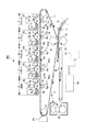
図1は第1実施形態の画像形成装置の概略構成の説明図、図2は1つの画像形成部を取り出した拡大図である。図1に示すように、本実施形態の画像形成装置100は、中間転写ベルト11を用いた、6連ドラム方式(インライン方式、タンデム方式)の電子写真フルカラー複写機であり、各種用紙・OHPシート・布などのシート状の記録材Pにフルカラー画像を形成して出力することができる。
<Image forming apparatus>
FIG. 1 is an explanatory diagram of a schematic configuration of the image forming apparatus according to the first embodiment, and FIG. As shown in FIG. 1, an
制御部50(具体的構成は省略)は、演算機能、画像処理機能、制御機能、ドライバ、IO回路等を備えて画像形成装置100を統括制御する。リーダー部51(具体的構成は省略)は、制御部50に制御されるとともに、カラー原稿の光電読取り、色分解を行って、電気的画像情報を制御部50に出力する。
The control unit 50 (specific configuration is omitted) includes an arithmetic function, an image processing function, a control function, a driver, an IO circuit, and the like, and performs overall control of the
中間転写ベルト11(転写媒体)の上向き直線区間に、図中左から右に、画像形成部A、B、C、D、E、Fが直列に配列される。画像形成部A、B、C、D、E、Fは、現像に用いるトナーの色と、後述する一次転写ニップ部7(a〜d)とは異なるものの、その他はほぼ共通にユニット化されたレーザー走査露光方式の電子写真プロセスユニットである。従って、図2に示すように、参照記号から画像形成部A、B、C、D、E、Fの別を表すa、b、c、d、e、fの記号を除いて共通に説明する。 In the upward linear section of the intermediate transfer belt 11 (transfer medium), the image forming units A, B, C, D, E, and F are arranged in series from left to right in the drawing. The image forming portions A, B, C, D, E, and F are different from the toner color used for development and the primary transfer nip portion 7 (a to d) to be described later, but the rest are almost unitized. This is a laser scanning exposure type electrophotographic process unit. Therefore, as shown in FIG. 2, the description will be made in common except for the reference symbols, a, b, c, d, e, and f representing the image forming units A, B, C, D, E, and F. .
感光ドラム1は、回転駆動される直径30〜80[mm]のドラム型の電子写真感光体である。感光ドラム1の周速度である画像形成スピード(画像形成装置100のプロセススピード)は200[mm/sec]以上である。
The
帯電ローラ2は、回転する感光ドラム1の表面を所定の極性、電位に一様に帯電する。露光装置(レーザースキャナ)3は、画像情報信号に対応して変調されたレーザ光Lを出力して、感光ドラム1の一様帯電面を走査露光して、感光ドラム1表面に露光パターンに対応した静電潜像を形成する。
The
現像装置4は、感光ドラム1表面に形成された静電潜像をトナー像として現像する。トナーボトル(トナーカートリッジ:トナー補給容器)5は、現像装置4に対して着脱可能なトナー補給源である。
The developing
一次転写ローラ(転写部材)6は、中間転写ベルト(転写媒体)11を挟んで感光ドラム(像担持体)1の下面に当接し、中間転写ベルト11が矢印方向へ移動する際に回転する。感光ドラム1と中間転写ベルト11との当接部が一次転写ニップ部7である。転写バイアス印加電源(電圧印加手段)65は、一次転写ローラ6に、トナーの帯電極性とは逆極性の所定電位の転写電圧を印加する。これにより、回転する感光ドラム1の表面から循環する中間転写ベルト11の表面へトナー像が一次転写される。
The primary transfer roller (transfer member) 6 is in contact with the lower surface of the photosensitive drum (image carrier) 1 with the intermediate transfer belt (transfer medium) 11 interposed therebetween, and rotates when the
ドラムクリーニング装置8は、中間転写ベルト11に対するトナー像の一次転写後の感光ドラム1表面から一次転写残トナーを除去して感光ドラム1表面を清掃する。感光ドラム1の回転する表面は、ドラムクリーニング装置8で清掃された後、繰り返して画像形成に供される。本実施形態において、ドラムクリーニング装置8は、感光ドラム1の母線方向に長い弾性ゴムブレード(クリーニングブレード)であり、回転する感光ドラム1の面に対してカウンター方向に当接させてある。廃トナー容器9は、ドラムクリーニング装置8が感光ドラム1の表面から掻き落とした一次転写残トナーを貯留する。
The
図1に示すように、画像形成部A、B、C、D、E、Fは、それぞれ、感光ドラム1a、1b、1c、1d、1e、1fの表面に、目的のカラー原稿画像の色分解成分色に対応したトナー像を形成する。それぞれライトマゼンタ(LM)、ライトシアン(LC)、イエロー(Y)、マゼンタ(M)、シアン(C)、ブラック(Bk)のトナー像が形成される。従って、現像装置4a、4b、4c、4d、4e、4fおよびトナーボトル5a、5b、5c、5d、5e、5fは、ライトマゼンタトナー、ライトシアントナー、イエロートナー、マゼンタトナー、シアントナー、ブラックトナーを収納する。
As shown in FIG. 1, the image forming units A, B, C, D, E, and F respectively color-separate target color original images on the surfaces of the
中間転写ベルト11は、樹脂やゴム製の可撓性の無端ベルトであって、並行するテンションローラ12と駆動ローラ13と二次転写内ローラ14とに懸架張設されている。中間転写ベルト11は、テンションローラ12によって駆動されて、矢印方向に、感光ドラム1a、1b、1c、1d、1e、1fの回転速度と略同じ速度で循環する。
The
テンションローラ12と駆動ローラ13との間に位置する中間転写ベルト11の水平部分に、一次転写ニップ部7a、7b、7c、7d、7e、7fが配列する。一次転写ニップ部7a、7b、7c、7d、7e、7fは、それぞれ一次転写ローラ6a、6b、6c、6d、6e、6fが中間転写ベルト11を押圧して、感光ドラム1a、1b、1c、1d、1e、1fに圧接させる。
Primary transfer nip
中間転写ベルト11は、一次転写ニップ部7a、7b、7c、7d、7e、7fにて順番に一次転写されたトナー像を重ねて担持する。先ず、画像形成部Aの一次転写ニップ部7aにおいて、感光ドラム1aに形成される1色目のライトマゼンタトナー像が循環する中間転写ベルト11の表面に一次転写される。次いで、画像形成部Bの一次転写ニップ部7bにおいて、感光ドラム1bに形成される2色目のライトシアントナー像が、中間転写ベルト11上の1色目のライトマゼンタトナー像に重ね合せて一次転写される。同様にして、画像形成部C、D、E、Fの一次転写ニップ部7c、7d、7e、7fにおいて、3、4、5、6色目のイエロートナー像、マゼンタトナー像、シアントナー像、ブラックトナー像が順次に重畳転写される。
The
すなわち、中間ベルト11上に、ライトマゼンタ、ライトシアン、イエロー、マゼンタ、シアン、ブラックの合計6色のトナー像が多重転写されて、フルカラーの未定着トナー画像が形成される。
That is, a total of six color toner images of light magenta, light cyan, yellow, magenta, cyan, and black are transferred onto the
中間転写ベルト11上に形成されたフルカラーの未定着トナー画像は、引き続く中間転写ベルト11の循環移動により、二次転写ニップ部16に搬送される。二次転写ニップ部16は、二次転写内ローラ14のベルト懸け回し位置において、二次転写ローラ15を中間転写ベルト11に当接させた部位である。
The full-color unfixed toner image formed on the
一方、所定の制御タイミングで、不図示の給紙機構部の給紙カセットからシート状の記録材Pが一枚づつ分離して給送され、回転を停止しているレジストローラ対17のニップ部に記録材Pの先端が受け止められる。これにより、記録材Pは斜行修正される。
On the other hand, at a predetermined control timing, the sheet-like recording material P is separated and fed one by one from a paper feed cassette of a paper feed mechanism unit (not shown), and the nip portion of the
記録材Pは、中間転写ベルト11上のフルカラーの未定着トナー画像にタイミングを合わせて、レジストローラ対17が回転駆動されることにより、二次転写ニップ部16に搬送される。すなわち、フルカラーの未定着トナー画像の画像先端が二次転写ニップ部16に到達するタイミングで、二次転写ニップ部16に記録材Pのプリント開始位置が到達するように、レジストローラ対17の回転開始が制御される。そして、記録材Pが二次転写ニップ部16を挟持搬送されていく過程において、二次転写ローラ15に対して不図示の転写バイアス印加電源からトナーの帯電極性とは逆極性の所定電位の転写電圧が印加される。これにより、中間転写ベルト11上のフルカラーの未定着トナー画像は、記録材Pに対して一括二次転写される。
The recording material P is conveyed to the secondary transfer nip
二次転写ニップ部16を出た記録材Pは、中間転写ベルト11から曲率分離して、搬送ベルト18に乗せ替えられて定着装置19に搬送される。定着装置19は、ヒートローラ191と加圧ローラ192とのローラ対を基本構成部材とする熱圧定着装置である。記録材Pは、ヒートローラ191と加圧ローラ192との圧接部である定着ニップ部に挟持搬送される過程で熱と圧力を受ける。これにより、各色トナー像のトナーが溶融混色してフルカラープリント画像として記録材表面に定着(永久固着画像化)され、フルカラープリントが機外に排出される。
The recording material P that has exited the secondary transfer nip 16 is separated from the
記録材Pが曲率分離された後の中間転写ベルト11は、ベルトクリーナ20によって表面から二次転写残トナーを除去してクリーニングされ、次回の作像、一次転写工程に備える。
The
なお、モノクロ画像形成モードの場合、ブラックトナー像の画像形成部Fだけが画像形成動作して、感光ドラム1fに形成されたブラックトナー像が中間転写ベルト11に一次転写される。また、画像形成部A、B、C、D、Eは、感光ドラム1a、1b、1c、1d、1eを中間転写ベルト11に追従回転させるのみで、画像形成動作はしない。そして、画像形成部Fで一次転写されたブラックトナー像が二次転写ニップ部16において記録材Pに二次転写され、中間転写ベルト11から分離して定着装置19へ搬送され、ブラックトナー画像を定着される。そして、モノクロ画像プリントが機外に排出される。
In the monochrome image forming mode, only the image forming portion F of the black toner image performs the image forming operation, and the black toner image formed on the
図2に示すように、現像装置4は、現像容器41の内側に、現像スリーブ42と現像剤攪拌搬送スクリュー軸43とを配設し、現像容器41の上側にトナーホッパー44を配設する。トナー補給源であるトナーボトル5は、トナーホッパー44の上に着脱可能に装着される。トナーボトル5内のトナーがトナーホッパー44を介して現像容器41内に逐次に補給されて、現像容器41で消費したトナーが補われる。現像容器41内の現像剤は1成分系あるいは2成分系である。
As shown in FIG. 2, the developing
現像スリーブ42は、僅少なギャップを介在させて感光ドラム1に対向して、対向する感光ドラム1の表面の移動方向に回転駆動される。現像容器41内の現像剤は、スクリュー軸43により攪拌され、回転する現像スリーブ42に担持されて、感光ドラム1との対向部に搬送される。不図示の現像バイアス印加電源から所定の現像バイアスが現像スリーブ42に印加されることにより、現像スリーブ42に担持された現像剤中のトナーが感光ドラム1の表面へ移動する。各色のトナーが静電潜像に電気的に付着することにより、静電潜像が各色のトナー像として現像される。
The developing sleeve 42 is rotationally driven in the moving direction of the surface of the opposing
なお、画像形成部A、B、C、D、E、Fは、それぞれ感光ドラム1、帯電ローラ2、現像装置4、クリーニング装置8、廃トナー容器9を1ユニット化して、画像形成装置100に対し着脱可能なプロセスカートリッジとしてある。そして、それぞれのプロセスカートリッジ内にトナーボトル5をも含んだ、ALL−IN−ONEカートリッジとすることもできる。
In each of the image forming units A, B, C, D, E, and F, the
<第1実施形態>
図3は淡トナーと濃トナーとにおけるトナー載り量と光学濃度との関係を示す線図、図4は淡トナーと濃トナーとを画像濃度に割り当てるルックアップテーブルの線図である。図5は画像入力信号値と画像濃度との関係を示す線図、図6は転写ニップが同一時の感光ドラム上のトナー付着量に対する転写効率の関係を示す線図である。
<First Embodiment>
FIG. 3 is a diagram showing the relationship between the applied toner amount and the optical density of the light toner and the dark toner, and FIG. 4 is a diagram of a lookup table for assigning the light toner and the dark toner to the image density. FIG. 5 is a diagram showing the relationship between the image input signal value and the image density, and FIG. 6 is a diagram showing the relationship between the transfer efficiency and the toner adhesion amount on the photosensitive drum when the transfer nip is the same.
以下の説明における画像濃度(定着後画像の光学濃度)は、X−Rite社製のスペクトロデンシトメーター504で測定したもので、測定画像を任意に5回測定し、平均の値を画像濃度とした。 The image density (optical density of the image after fixing) in the following description is measured with a spectrodensitometer 504 manufactured by X-Rite, and the measured image is arbitrarily measured five times, and the average value is determined as the image density. did.
また、転写効率は、感光ドラム上の転写前後のトナー像のX−Rite濃度の変化から求めた。感光ドラム1に担持された転写前のトナー像と転写後のトナー像とをポリエステルフィルムの接着テープで移し取り、それぞれのテープを転写紙に貼り付け、X−Rite濃度測定を行なった。転写前の濃度をDa、転写後の濃度をDb、テープのみの濃度をDcとしたとき、転写効率は次式で定義される。
The transfer efficiency was determined from the change in X-Rite density of the toner image before and after transfer on the photosensitive drum. The toner image before transfer and the toner image after transfer carried on the
転写効率={[(Da−Dc)−(Db−Dc)]/(Da−Dc)}×100 Transfer efficiency = {[(Da−Dc) − (Db−Dc)] / (Da−Dc)} × 100
すなわち、この値が高いほど転写効率が高く、転写性が良好である。 That is, the higher this value, the higher the transfer efficiency and the better the transferability.
また、感光ドラム1上あるいは記録材P上でのトナー載り量(単位面積当たりのトナー量)は、未定着であるトナーを所定形状を有する容器内に吸引し、吸引前後の容器の重量の差分と、吸引した面積とを測定し、容器の重量の差分を吸引した面積で除算することで求める。
Further, the amount of applied toner (toner amount per unit area) on the
画像形成部A、Bで使用されるライトマゼンタトナー、ライトシアントナー(淡トナー)は、それぞれ、記録材P上のトナー量が0.5[mg/cm2]のときに、定着後の光学濃度が0.7になるように設計されている。これに対して、イエロートナー、マゼンタトナー、シアントナー、ブラックトナー(濃トナー)は、それぞれ、記録材P上のトナー量が0.45[mg/cm2]のときに、定着後の光学濃度が1.4になるように設計されている。以下の説明では、ライトマゼンタトナー、ライトシアントナーを「淡トナー」と呼び、画像形成部A、Bを「淡トナー画像形成部」と呼ぶ。また、イエロートナー、マゼンタトナー、シアントナー、ブラックトナーを「濃トナー」と呼び、画像形成部C、D、E、Fを「濃トナー画像形成部」と呼ぶ。 The light magenta toner and the light cyan toner (light toner) used in the image forming portions A and B each have an optical density after fixing when the toner amount on the recording material P is 0.5 [mg / cm 2 ]. Is designed to be 0.7. In contrast, yellow toner, magenta toner, cyan toner, and black toner (dark toner) each have an optical density after fixing when the toner amount on the recording material P is 0.45 [mg / cm 2 ]. Is designed to be 1.4. In the following description, the light magenta toner and the light cyan toner are referred to as “light toner”, and the image forming units A and B are referred to as “light toner image forming unit”. In addition, yellow toner, magenta toner, cyan toner, and black toner are referred to as “dark toner”, and the image forming portions C, D, E, and F are referred to as “dark toner image forming portion”.
淡トナーと濃トナーとは、含有する色材(顔料や染料)の分光特性が等しく、色材の含有量を異ならせて淡色と濃色に着色されているトナーである。すなわち、淡トナーと濃トナーは、同一色相で、濃度が淡/濃に異なるトナーである。ただし、淡トナーは、記録材P上でのトナー量が0.5mg/cm2につき光学濃度が1.0未満であるように色材を調整しているトナーとしとしてもよい。濃トナーは、記録材P上でのトナー量が0.5mg/cm2につき光学濃度が1.0以上であるように顔料を調整しているトナーとしてもよい。 The light toner and the dark toner are toners that have the same spectral characteristics of the color materials (pigments and dyes) contained therein, and are colored in light and dark colors by varying the content of the color materials. That is, the light toner and the dark toner are toners having the same hue and different in light / dark. However, the light toner may be a toner whose color material is adjusted so that the optical density is less than 1.0 per 0.5 mg / cm 2 of toner on the recording material P. The dark toner may be a toner in which the pigment is adjusted so that the optical density is 1.0 or more per 0.5 mg / cm 2 on the recording material P.
濃トナーだけでも可能なカラー画像形成において、淡トナーを加える目的は、粒状感の低減による高画質化である。図3は、シアンの淡トナー(LC:二点鎖線)と、濃トナー(DC:実線)とにおけるそれぞれのカバーリングパワーを示している。図3に示すように、記録材P上における淡トナーのトナー載り量が0.5[mg/cm2]時の光学濃度(O.D)が0.7、記録材P上における濃トナーのトナー載り量0.45[mg/cm2]時の光学濃度が1.4である。ここで、記録材P上のトナー載り量[mg/cm2]は未定着状態での測定値、一方、光学濃度は、定着状態時での測定値である。 In color image formation that can be performed using only dark toner, the purpose of adding light toner is to improve image quality by reducing graininess. FIG. 3 shows respective covering powers of cyan light toner (LC: two-dot chain line) and dark toner (DC: solid line). As shown in FIG. 3, the optical density (OD) is 0.7 when the applied amount of light toner on the recording material P is 0.5 [mg / cm 2 ], and the dark toner on the recording material P The optical density when the applied toner amount is 0.45 [mg / cm 2 ] is 1.4. Here, the applied toner amount [mg / cm 2 ] on the recording material P is a measured value in an unfixed state, while the optical density is a measured value in a fixed state.
図4には、淡トナーと濃トナーとを用いて画像形成する際の、淡トナー用ルックアップテーブル(LC:二点鎖線)と、濃トナー用ルックアップテーブル(DC:実線)とが示される。図中、横軸は濃トナーと淡トナーに分版する前の画像の階調値で、縦軸は濃トナーおよび淡トナーに分版した際の各々の階調値である。分版とは、ある色(版またはチャンネルともいう)の画像データを、濃トナー用と淡トナー用の2つの画像データに分割することをいう。 FIG. 4 shows a light toner look-up table (LC: two-dot chain line) and a dark toner look-up table (DC: solid line) when an image is formed using light toner and dark toner. . In the figure, the horizontal axis represents the tone value of an image before color separation into dark toner and light toner, and the vertical axis represents the respective tone value when color separation is performed on dark toner and light toner. Separation means dividing image data of a certain color (also referred to as a plate or a channel) into two image data for dark toner and light toner.
なお、第1実施形態では、感光ドラム1に静電潜像を形成する際に、1画素を形成するためにレーザ光Lを感光ドラム1に照射する時間(光量)を調整することで、感光ドラム1上のトナー載り量を変更する。画像形成部A、Bの感光ドラム1における最大トナー載り量は0.5[mg/cm2]、画像形成部C、D、E、Fの感光ドラム1における最大トナー載り量は、0.45[mg/cm2]に調整した。
In the first embodiment, when an electrostatic latent image is formed on the
図4に示すように、目標とする画像濃度を得るための淡トナーと濃トナーとへの振り分け(画像形成部B、Eで潜像形成及び現像を行う際の入力信号値の分担)が行われる。図4に示す2つのルックアップテーブルに基づいて淡トナー像と濃トナー像とを重ね合わせることにより、図5に示すとおり、画像入力信号値に対して忠実なシアンの階調濃度が再現される。 As shown in FIG. 4, the distribution of light toner and dark toner (sharing of input signal values when forming and developing latent images in the image forming units B and E) to obtain a target image density is performed. Is called. By superimposing the light toner image and the dark toner image based on the two look-up tables shown in FIG. 4, cyan gradation density faithful to the image input signal value is reproduced as shown in FIG. .
図4に示すように、画像形成装置100では、従来の濃トナー単体での画像形成と異なり、画像信号の低濃度部において淡トナーを積極的に使用し、中間濃度部においては淡トナーと濃トナーを混合させ、高濃度部においては濃トナーを積極的に使用する。マゼンタの画像形成(画像形成部A、D)についても同様である。
As shown in FIG. 4, in the
これにより、低濃度部でドット密度を増して粒状感を低減し、高濃度部でのトナー量を抑え、自然画像等を出力する際に重要となる、中間調から明度の高い領域にかけて、広い色再現範囲を実現することが可能になる。その結果、中間調から明度の高い領域を多く使用する写真画像において、銀塩写真にも迫るなめらかで自然なグラデーションを持った高品質な画像形成を実現している。 This increases the dot density in the low density area to reduce graininess, suppresses the amount of toner in the high density area, and is important when outputting natural images etc. A color reproduction range can be realized. As a result, high-quality image formation with a smooth and natural gradation close to that of a silver salt photograph is realized in a photographic image that uses a lot of areas from halftone to high brightness.
ところで、4色の濃トナーと2色の淡トナーとを用いる従来の画像形成装置に関して、本発明者が種々検討を行ったところ、実際上および使用レベル上において、次のような問題が生じることを知見するに至った。例えば、一般的な約200万画素〜1000万画素の写真調カラー画像(人物、建物、空、海、山、雲、夜景、乗り物等を含む)を、図4に示すルックアップテーブルに基づいて、数百枚の画像形成(プリントアウト)を行った。その結果、濃トナーに対する淡トナーの消費量は約2.2倍になった。 By the way, when the present inventor has made various studies on the conventional image forming apparatus using the dark toner of the four colors and the light toner of the two colors, the following problems occur in practice and on the usage level. It came to know. For example, a general photographic color image (including a person, a building, the sky, the sea, a mountain, a cloud, a night view, a vehicle, and the like) of about 2 to 10 million pixels based on a lookup table shown in FIG. Several hundred images were formed (printed out). As a result, the consumption amount of the light toner with respect to the dark toner is about 2.2 times.
すなわち、写真画質に求められる中間調再現を担う淡トナーは、濃トナーに対し画像形成に関わる消費トナー量が増加する。同じ濃度を表現するために、濃トナーを用いる場合の2倍のトナー量を要する。また、濃色と淡色のトナーとが混在し始める濃度領域(以下つなぎ部)の不連続による擬似輪郭の発生の防止のため、淡トナーを使用する濃度領域をハイライトから高濃度部まで広範囲にわたらせる場合もある。この場合、淡トナーの濃トナーに対する消費量がさらに増加する。 In other words, the light toner responsible for halftone reproduction required for photographic image quality increases the amount of toner consumed for image formation compared to dark toner. In order to express the same density, a toner amount twice as large as that in the case of using a dark toner is required. Also, in order to prevent the occurrence of false contours due to the discontinuity of the density area (hereinafter referred to as “joint part”) where dark and light color toners begin to coexist, the density area where light toner is used is extended from highlights to high density parts. It may be spread. In this case, the consumption amount of the light toner with respect to the dark toner further increases.
また、写真画質に求められる自然画像等を出力する際には、中間調から明度の高い領域が重要となる。このため、図4に示すように、中間調から明度の高い領域にかけて広い色再現範囲及び粒状性の低減を実現するために、階調値の小さい高明度領域(ハイライト領域)では、淡トナーのみにより画像形成を行う。これによっても、淡トナーの消費量は濃トナーより多くなる。 Further, when outputting a natural image or the like required for photographic image quality, an area having a high brightness from a halftone is important. Therefore, as shown in FIG. 4, in order to realize a wide color reproduction range and graininess reduction from an intermediate tone to a high brightness area, light toner is used in a high brightness area (highlight area) with a small gradation value. Only by this, image formation is performed. This also increases the amount of light toner consumed than that of dark toner.
しかし、ハイライト領域から濃トナーと淡トナーを併せて使用すると、ハイライト領域の粒状性が低下する(トナーの粒状感が表れる)ため好ましくない。従って、形成される画像濃度が0.3以下の階調では、淡トナーのみを用い、濃トナーの使用率を0%にするとよい。これによっても、淡トナーの消費量は濃トナーより多くなる。
However, it is not preferable to use dark toner and light toner together from the highlight area because the graininess of the highlight area deteriorates (a graininess of the toner appears). Therefore, it is preferable to use only light toner and make the usage rate of
そして、階調値128までは、淡トナーの階調を増加させていき、階調値128を超えたところで淡トナーの階調を減少させていく。一方、濃トナーについては、階調値128を超えたところから濃トナーの階調を増加させていく。つまり、中間調領域では、淡トナーと濃トナーを併せて画像形成を行い、高濃度部には濃トナーにより画像形成することにより、高濃度部においては、トナー量を抑えて濃度を満たすことが可能となる。
The gradation of the light toner is increased up to the
このようにして得られた画像の濃度カーブを図5のグラフに示す。横軸は、図4と同じく画像の階調値であり、縦軸は、画像の濃度である。高明度領域で淡トナーのみを使用し、かつ、中間調領域で濃トナーと淡トナーを併せて使用することにより、良好な階調再現性が得られていることがわかる。 The density curve of the image thus obtained is shown in the graph of FIG. The horizontal axis is the gradation value of the image as in FIG. 4, and the vertical axis is the density of the image. It can be seen that good gradation reproducibility is obtained by using only the light toner in the high brightness region and using the dark toner and the light toner together in the halftone region.
以上のように、中間調から明度の高い領域を多く使用する写真画像において写真画質を実現するには、濃トナーに対する淡トナーの消費量(単位面積当たりのドラム上のトナー付着量:トナー載り量)が多くなる。図1に示すように、淡トナー像を形成する淡トナー画像形成部A、Bの感光ドラム1a、1b上のトナー載り量は、濃トナー像を形成する濃トナー画像形成部C、D、E、Fの感光ドラム1c、1d、1e、1f上のトナー載り量より多くなる。
As described above, in order to achieve photographic image quality in a photographic image that uses a large area of lightness from halftone, the consumption amount of light toner with respect to dark toner (toner adhesion amount on the drum per unit area: toner application amount) ) Will increase. As shown in FIG. 1, the amount of toner applied on the photosensitive drums 1a and 1b of the light toner image forming portions A and B that form the light toner images is determined by the dark toner image forming portions C, D, and E that form the dark toner images. , F of the
しかし、図2に示すように、定電圧方式の一次転写では、感光ドラム1上のトナー載り量が多いと、感光ドラム1上のトナー載り量が少ない場合と比較して転写効率が低下する傾向にある。感光ドラム1上のトナー載り量に対する転写効率の関係を図6に示す。図6におけるトナー付着量大(破線)は、ドラム上で0.5[mg/cm2]時、トナー付着量小(実線)は、0.3[mg/cm2]時である。図6に示すように、感光ドラム1上のトナー載り量が多いと転写効率は低下してしまう。
However, as shown in FIG. 2, in the primary transfer of the constant voltage method, when the amount of toner applied on the
トナー載り量が多いと転写効率が低下してしまう理由は以下である。一次転写においてトナーを転写するために必要な転写電流はトナーのトリボ(電荷量)と感光ドラム上のトナー載り量の積に比例し、トナー載り量が少ない場合には少ない転写電流、多い場合には多い転写電流が必要となる。そのため、過大な転写電流を流した場合には、被転写媒体上に転写された一部のトナーの帯電極性が変わってしまい、再びドラム上に付着してしまう現象(再転写現象)が発生し、転写効率の低下を招いてしまう。 The reason why the transfer efficiency decreases when the amount of applied toner is large is as follows. The transfer current required for transferring the toner in the primary transfer is proportional to the product of the toner tribo (charge amount) and the amount of applied toner on the photosensitive drum. When the amount of applied toner is small, the transfer current is small. Requires a large transfer current. For this reason, when an excessive transfer current is applied, the charge polarity of a part of the toner transferred onto the transfer medium changes and a phenomenon (retransfer phenomenon) occurs that adheres to the drum again. As a result, the transfer efficiency is lowered.
このため、淡トナー画像形成部A、Bと濃トナー画像形成部C、D、E、Fとで一次転写条件が同一であると、淡トナー画像形成部A、Bは、濃トナー画像形成部C、D、E、Fより転写効率が低下する。これにより、画像の品質低下を招き、直接的には画像濃度が低下する問題が発生したり、また、転写工程後に感光体表面に残留する未転写トナーが多くなってトナーの無駄な消費をしたりする。さらに、ドラム上の残トナーを排除するためのクリーニング装置に負荷がかかってしまう。 Therefore, if the primary transfer conditions are the same in the light toner image forming units A and B and the dark toner image forming units C, D, E, and F, the light toner image forming units A and B Transfer efficiency is lower than C, D, E, and F. As a result, the quality of the image is deteriorated, and the problem that the image density is directly reduced occurs. Further, the amount of untransferred toner remaining on the surface of the photoconductor after the transfer process increases, and the toner is wasted. Or Furthermore, a load is applied to the cleaning device for removing the residual toner on the drum.
そこで、第1実施形態では、一次転写ローラ6の圧接力を増して転写面積を増大させることにより、転写電流が増えても過剰に転写電流密度が増えないようにして、転写効率の低下を抑制した。図7は第1実施形態における一次転写条件の説明図、図8は一次転写ローラの斜視図である。図9は中間転写ベルトが感光ドラムに接触する送り方向長さの説明図、図10は中間転写ベルトが感光ドラムに接触する送り方向長さと転写効率との関係を示す線図である。
Therefore, in the first embodiment, the pressure contact force of the
図7に示すように、一次転写ローラ6は、金属性の芯体69と、芯体69の外周に設けられた導電性発泡ウレタンよりなる弾性層61とから構成された直径18mmのローラである。芯体69と弾性層61の表面との間の電気抵抗は約104Ωである。芯体69には転写バイアス印加電源65が接続されている。弾性層61の硬度は、JIS−A硬度測定法で測定したところ45°であった。
As shown in FIG. 7, the
図8に示すように、転写ローラ6は、不図示のモータから駆動力を受けて、芯体69を回転中心軸として回転する。芯体69は、軸受け63f、63rによって両持ち支持され、軸受け63f、63rには、それぞれバネ47f、47rが設けてある。バネ47f、47rは、軸受け63f、63rを介して芯体69を付勢し、一次転写ローラ6の弾性層61を中間転写ベルト11の内側面に弾性的に当接させる。
As shown in FIG. 8, the
図1に示すように、一次転写ローラ6a、6bの構成は、一次転写ローラ6c、6d、6e、6fとほぼ同様である。しかし、転写ローラ6a、6bにおいて転写ローラ6c、6d、6e、6fと異なるのは、図8に示すバネ47f、47rによる付勢力の大きさ、したがって、中間転写ベルト11と感光ドラム1との接触圧である。第1実施形態では、表1に示すように、転写ローラ6a、6bの付勢力を10〔N〕とし、転写ローラ6c、6d、6e、6fの付勢力を8〔N〕とした。付勢力は、バネ47fによる付勢力とバネ47rによる付勢力との合計を指しており、その大きさはバネ47f及びバネ47rの弾性強度を変えることにより調整した。
As shown in FIG. 1, the configuration of the

つまり、第1実施形態では、淡トナー画像形成部A、Bの一次転写ローラ(第1転写部材)6a、6bの付勢力が、濃トナー画像形成部C、D、E、Fの一次転写ローラ6c、6d、6e、6f(第2転写部材)より大きい。これにより、淡トナー画像形成部A、Bでは、濃トナー画像形成部C、D、E、Fよりも、図9に示すように、弾性層61が大きく変形し、弾性層61が中間転写ベルト11に接触する送り方向長さ(当接幅Dtr)が長い。圧接幅Dtrが長いので、画像形成部A、Bでは、画像形成部C、D、E、Fよりも、中間転写ベルト11が感光ドラム1に接触する送り方向長さ(転写幅Dph)が長い。このように一次転写ローラ6を付勢した時の、当接幅Dtrと転写幅Dphを測定した結果を表1に示している。転写効率が95[%]以上になるための転写幅から表に示す付勢力にした。
That is, in the first embodiment, the urging forces of the primary transfer rollers (first transfer members) 6a and 6b of the light toner image forming portions A and B are the primary transfer rollers of the dark toner image forming portions C, D, E, and F. It is larger than 6c, 6d, 6e, and 6f (second transfer member). As a result, in the light toner image forming portions A and B, as shown in FIG. 9, the
当接幅Dtrは、中間転写ベルト11と一次転写ローラ6とが当接する領域の中間転写ベルト11移動方向の長さのことを指す。また、転写幅Dphは、中間転写ベルト11と感光ドラム1とが当接する領域(転写ニップ)の中間転写ベルト11移動方向の長さを指す。当接幅Dtrは、中間転写ベルト11の内側面に現像剤を付着させた部分を形成し、停止状態の一次転写ローラ6と感光ドラム1との間にこの部分を摺擦通過させた後に、一次転写ローラ6に付着した現像剤領域の長さを測定した。転写幅Dphは、感光ドラム1に現像剤を付着させて、固定した中間転写ベルト11上で回転させ、感光ドラム1と中間転写ベルト11との摺接によって中間転写ベルト11に付着した現像剤領域の幅を測定した。
The contact width Dtr indicates the length in the moving direction of the
図10に転写幅Dphと転写効率との関係を示す。図10に示すように、感光ドラム上のトナー載り量(付着量)が多いほうが、上記に説明したように転写効率が下がってしまう。しかし、転写幅Dphが長いほうが、トナーを中間転写ベルト11に転写できる時間が長くなるので、転写効率が高くなる。
FIG. 10 shows the relationship between the transfer width Dph and the transfer efficiency. As shown in FIG. 10, the transfer efficiency decreases as the amount of applied toner (attachment amount) on the photosensitive drum increases. However, as the transfer width Dph is longer, the time during which the toner can be transferred to the
また、転写電界が作用する転写面積が広がって、トナー量の多さに応じて転写電流を増やしても転写電流密度の上昇が抑制されるので、中間転写ベルト11上に転写された一部のトナーの帯電極性が変わりにくくなる。これにより、トナーの帯電極性が変わって再び感光ドラム1上に付着してしまう現象(再転写現象)がもたらす転写効率の低下が少なくなる。
In addition, since the transfer area on which the transfer electric field acts increases and the transfer current is increased according to the amount of toner, an increase in transfer current density is suppressed, so that a portion of the image transferred onto the
図1に示す制御部50は、放電現象により転写不良の発生しない範囲で、淡トナーの一次転写ローラ6a、6bに印加するバイアス電圧の大きさを、濃トナーの一次転写ローラ6c、6d、6e、6fに印加するバイアス電圧よりも大きくしている。そして、転写バイアス印加電源65a、65bは、一次転写ローラ6a、6bに、12μAの電流が流れるように転写電圧を印加している。また、転写バイアス印加電源65c、65d、65e、65fは、一次転写ローラ6c、6d、6e、6fに、10μAの電流が流れるように転写電圧を印加している。
The
実際、第1実施形態の画像形成装置100によって一次転写を行ったところ、淡トナーの一次転写ニップ部7a、7bでの転写効率は、95%と良好な一次転写が行われた。また、比較のため、転写ローラ6a、6bの付勢力を全て8〔N〕としたところ、同じ一次転写ニップ部7a、7bでの転写効率は85%であった。
Actually, when the primary transfer was performed by the
第1実施形態では、図1に示す淡トナー画像形成部A、Bの一次転写ニップ部7a、7bは、濃トナー画像形成部C、D、E、Fの一次転写ニップ部7c、7d、7e、7fより付勢力が大きい。これにより、常に感光ドラム1と中間転写ベルト11とを良好に当接させて良好な一次転写を行うことができる。
In the first embodiment, the primary transfer nip
第1実施形態では、一次転写ニップ部7a、7bの当接幅Dtr、転写幅Dphが、一次転写ニップ部7c、7d、7e、7fの値よりも大きくなっている。ただし、どの一次転写ニップ部7(a〜f)においても、Dtr≦Dphが満たされている。
In the first embodiment, the contact width Dtr and the transfer width Dph of the primary transfer nip
当接幅Dtrは大きくすることが望ましいが、同時にDtr≦Dphを満たしていることが望ましい。何故なら、Dtr>Dphの場合、中間転写ベルト11と感光ドラム1とが当接していない領域A及び領域Bにも、転写電界が作用するからである。特に、上流側の領域Aに転写電界が作用した場合には、感光ドラム1上に形成されているトナー像の一部が中間転写ベルト11上に飛散するので好ましくない。従って、Dtr≦Dphであることが望ましい。
The contact width Dtr is desirably large, but at the same time, it is desirable that Dtr ≦ Dph is satisfied. This is because when Dtr> Dph, the transfer electric field also acts on the regions A and B where the
第1実施形態では、図9に示す一次転写ローラ6の弾性層61の硬度が全て等しいため、一次転写ローラ6の付勢力に格差を付けることで、必要な転写幅Dphの格差を容易に設定できる。淡トナー画像形成部A、Bの一次転写ローラ6a、6bの付勢力は、濃トナー画像形成部C、D、E、Fの一次転写ローラ6c、6d、6e、6fの付勢力より2〔N〕増加している。これにより、淡トナーの転写幅Dph2.8mmは、濃トナーの転写幅Dph2.3mmに対して過不足なく大きく設定されている。
In the first embodiment, since the hardness of the
しかし、特にこれに限定されることではなく、例えば、一次転写ローラ6の付勢力を揃える一方で、転写ローラ6の弾性層61の硬度を2種類に選択して、必要な転写幅Dphの格差を設定してもよい。転写ローラ6の弾性層61の硬度と付勢力の調整とを組み合わせて、必要な転写幅Dphの格差を設定してもよい。
However, the present invention is not particularly limited thereto. For example, while the urging force of the
なお、中間転写ベルト11の材料としては、体積抵抗が108〜1013Ω・cmの半導電性を示す材料を使用してもよい。例えば、カーボン粒子を分散させたポリイミドのほかに、ポリエチレンテレフタレート、ポリカーボネイト、ポリテトラフルオロエチレン等にカーボン粒子等の導電性粒子を分散させたものがある。導電性粒子を用いないで組成調整によって電気抵抗を調整した高分子フイルムを用いてもよい。さらには、このような高分子フイルムにイオン導電性物質を混入したもの、あるいは比較的電気抵抗が低いシリコンゴム、ウレタンゴム等のゴム材を用いてもよい。一次転写ローラ6の材料も、上述したウレタンに限らず、シリコンゴム等の各種ゴムが使用できる。
In addition, as the material of the
ところで、すべての画像形成部A、B、C、D、E、Fで当接幅Dtr、転写幅Dphを長くすると、中間転写ベルト11の循環に要する駆動トルクが増大して電力消費が増えてしまう。
Incidentally, all the image forming unit A, B, C, D, E, contact with F width Dtr, if the longer transfer width Dph, the driving torque required for the circulation of the intermediate rolling
また、濃トナーは、転写幅Dphを長くしたことによる出力画像上の弊害(飛び散りやがさつき)が目立つので、淡トナーの転写効率の向上による画質向上が全体的に見て打ち消されてしまう。そして、濃トナーは、トナー載り量が少なく現像されるので元々転写効率が高く、転写幅Dphをこれ以上長くしても転写効率はさほど向上しない。 Further, since dark toner has a noticeable adverse effect on the output image due to the increase in the transfer width Dph (scattering and harshness), the improvement in the image quality due to the improvement in the transfer efficiency of the light toner is negated as a whole. Since dark toner is developed with a small amount of applied toner, the transfer efficiency is originally high, and even if the transfer width Dph is longer than this, the transfer efficiency is not improved so much.
一方、淡トナーは、転写幅Dphを長くしたことによる弊害(飛び散りやがさつき)は、濃トナーほどには目立たないが、トナー載り量が多く現像されるため、転写幅Dphを長くすることによる効果は絶大である。淡トナーの転写にとっては、ベタを記録材P上にしっかり載せること(転写効率向上)が最重要となる。 On the other hand, the adverse effect (scattering and rustling) of the light toner due to the increase in the transfer width Dph is not as noticeable as that of the dark toner, but the amount of applied toner is developed so that the transfer width Dph is increased. The effect is tremendous. For the transfer of the light toner, it is most important that the solid is firmly placed on the recording material P (improvement of transfer efficiency).
これらの知見に基づいて、第1実施形態では、淡トナー画像形成部A、Bについてのみ一次転写ニップ部7の当接幅Dtr、転写幅Dphを長くした。濃トナー画像形成部C、D、E、Fについては、一次転写ニップ部7の当接幅Dtr、転写幅Dphを短くした。
Based on these findings, in the first embodiment, the contact width Dtr and the transfer width Dph of the primary transfer nip 7 are increased only for the light toner image forming portions A and B. For the dark toner image forming portions C, D, E, and F, the contact width Dtr and transfer width Dph of the primary transfer nip
ここで、一次転写ニップ部7の転写幅Dphと飛び散りとの関係について述べる。飛び散りは、図9に示す領域Aの転写前ギャップ部(転写ニップ上流部)で発生する。一次転写ニップ部7の転写幅Dphを広げると、転写前ギャップ部における中間転写ベルト11と感光ドラム1との距離が近くなり、転写前ギャップ部にかかる電界がより大きくなって、飛び散りが悪くなる。
Here, the relationship between the transfer width Dph of the primary transfer nip
また、中間転写ベルト11上に、2色目、3色目とトナー像を重ねていくうちに、中間転写体ベルト11の表面にトナー像と同極性の電荷が蓄積される。このため、特に最後の画像形成部Fにおける一次転写に際して、転写前ギャップ部に、感光ドラム1f上のトナー像が中間転写ベルト11に向かう方向の電界が発生して、トナーの飛び散りが悪くなってしまう。
Further, as the second and third color toner images are superimposed on the
<第2実施形態>
図11は第2実施形態の画像形成装置の概略構成の説明図である。第2実施形態では、一次転写ローラ6aL、6bLの直径を大きくしてその転写幅Dphを第1実施形態と同程度に設定した。これ以外の構成および制御は、第1実施形態と同一なので、図2〜図10を合わせて用い、また、図1と共通する部材には共通の符号を付して重複する説明を省略する。
Second Embodiment
FIG. 11 is an explanatory diagram of a schematic configuration of the image forming apparatus according to the second embodiment. In the second embodiment, the diameters of the primary transfer rollers 6aL and 6bL are increased and the transfer width Dph is set to the same level as in the first embodiment. Since other configurations and controls are the same as those in the first embodiment, FIG. 2 to FIG. 10 are used together, and members that are the same as those in FIG.
第2実施形態の画像形成装置200は、濃トナーの一次転写ローラ6c、6d、6e、6fとは直径の異なる淡トナーの一次転写ローラ6aL、6bLを有している。淡トナーの一次転写ローラ6aL、6bLの直径は22mm、濃トナーの一次転写ローラ6c、6d、6e、6fの直径は16mmである。
The
一次転写ローラ6aL、6bL、6c、6d、6e、6fは、全て中間転写ベルト11の内側面へ付勢されており、図8に示すバネ47f、47rによる付勢力は、全て8〔N〕である。第2実施形態における一次転写ニップ部7における当接幅Dtr、転写幅Dphは、表2に示すとおりである。即ち、一次転写ニップ部7a、7bでは、当接幅Dtrは2.8mm、転写幅Dphは2.8mmである。一次転写ニップ部7c、7d、7e、7fでは、当接幅Dtrは2.1mm、転写幅Dphは2.3mmである。
The primary transfer rollers 6aL, 6bL, 6c, 6d, 6e, and 6f are all urged toward the inner surface of the
第2実施形態では、一次転写ローラ6aL、6bL、6c、6d、6e、6fの付勢力は全て等しいが、淡トナーの一次転写ローラ6aL、6bLの直径は、濃トナーの一次転写ローラ6c、6d、6e、6fより大きい。このため、淡トナー画像形成部A、Bは、濃トナー画像形成部C、D、E、Fより、感光ドラム1と中間転写ベルト11との当接長さが大きくなり、安定した一次転写を行うことができる。
In the second embodiment, the urging forces of the primary transfer rollers 6aL, 6bL, 6c, 6d, 6e, and 6f are all equal, but the diameters of the primary transfer rollers 6aL and 6bL of the light toner are the
第2実施形態では、淡トナーの一次転写ローラ6aL、6bLの直径を濃トナーの一次転写ローラ6c、6d、6e、6fより大きくして、転写幅Dphの格差を第1実施形態と同程度に設定した。
In the second embodiment, the diameters of the primary transfer rollers 6aL and 6bL of the light toner are made larger than the
第2実施形態では、淡トナーの一次転写ローラ6a、6bの直径が濃トナーの一次転写ローラ6c、6d、6e、6fより大きいので、感光ドラム1a、1bのトナー載り量が多くても、十分な転写性能が得られる。一次転写ローラ6の直径を大きくすると、転写時間が長くなり、かつ、転写電界および押圧力が均一になって転写性が向上するからである。また、転写するトナー量の多さに応じた大きな転写電流を転写電流密度を上げることなく確保できるので、中間転写ベルト11上に転写されたトナーの極性反転に伴う転写効率の低下も少なくなる。従って、トナー載り量が多くても、出力画像上で転写効率の低下が目立たなくなる。
In the second embodiment, since the diameter of the
また、転写電界が転写方向に対して垂直になるため、転写電界のゆがみに起因する画像乱れが発生しにくくなる。 Further, since the transfer electric field is perpendicular to the transfer direction, image disturbance due to the distortion of the transfer electric field is less likely to occur.
しかし、一次転写ローラ6の直径を大きくし過ぎると、トナー像が押圧されている時間が長くなるため、機械的振動等による画像乱れは増大する。そのため、感光ドラム1の直径にもよるが、第1実施形態で言えば、一次転写ローラ6の直径は30mm以下が望ましい。また、画像乱れが淡トナーに比較して目立つ濃トナーでは、一次転写ローラ6の直径を小さくすることが望ましい。
However, if the diameter of the
なお、第1実施形態と第2実施形態とを組み合わせても良い。淡トナーの一次転写ローラ6aL、6bLの直径を濃トナーの一次転写ローラ6c、6d、6e、6fより大きくする構成において、画像形成部A、Bでは図8に示すバネ47f、47rを画像形成部C、D、E、Fのバネ47f、47rよりも強くする。このように構成することで、淡トナー画像形成部A、Bの一次転写ローラ6aL、6bLがより一層感光ドラム1a、1bに安定して当接し、転写効率の向上が実現される。ただし、このような場合においても、上述したように、Dtr≦Dphの関係を満たしていることが望ましい。
Note that the first embodiment and the second embodiment may be combined. In the configuration in which the primary transfer rollers 6aL and 6bL of the light toner are larger in diameter than the
また、第1実施形態と同じ理由により、淡トナー画像形成部A、Bについてのみ一次転写ニップ部7の当接幅Dtr、転写幅Dphを長くした。濃トナー画像形成部C、D、E、Fについては、一次転写ニップ部7の当接幅Dtr、転写幅Dphを短くした。
For the same reason as in the first embodiment, the contact width Dtr and transfer width Dph of the primary transfer nip 7 are increased only for the light toner image forming portions A and B. For the dark toner image forming portions C, D, E, and F, the contact width Dtr and transfer width Dph of the primary transfer nip
<第3実施形態>
第1実施形態、第2実施形態では、専ら淡トナーと濃トナーとを組み合わせて画像形成する画像形成装置100、200を説明した。しかし、本発明は、透明トナーを濃トナーに組み合わせて画像形成する画像形成装置においても同様に実施して、同等、またはそれ以上の転写効率の改善効果が得られる。
<Third Embodiment>
In the first embodiment and the second embodiment, the
図12は第3実施形態の画像形成装置の概略構成の説明図である。第3実施形態の画像形成装置300は、第2実施形態における淡トナー画像形成部A、Bを透明トナー画像形成部Gに置き換えて構成される。これ以外の構成および制御は、第2実施形態と同一なので、図12中、図11と共通する部材には共通の符号を付し、また、図2に示す画像形成部内の構成には添え字gを付して、重複する説明を省略する。
FIG. 12 is an explanatory diagram of a schematic configuration of the image forming apparatus according to the third embodiment. The
図12に示すように、透明トナー画像形成部Gは、感光ドラム1gに透明トナーの透明トナー像を形成して担持させるプロセスカートリッジである。透明トナー画像形成部Gにおいても、帯電ローラ2gによって感光ドラム1gの表面が帯電され、続いて露光装置3gがレーザ光Lを照射して感光ドラム1gの表面を露光して、静電潜像を形成する。トナーボトル5gには、透明トナーが収められ、現像装置4gは、感光ドラム1g上の静電潜像を透明トナーで現像して透明トナー像を形成する。
As shown in FIG. 12, the transparent toner image forming unit G is a process cartridge that forms and carries a transparent toner image of transparent toner on the photosensitive drum 1g. Also in the transparent toner image forming part G, the surface of the photosensitive drum 1g is charged by the charging
一次転写ローラ6gLは、図8に示す機構を用いて、中間転写ベルト11を感光ドラム1gへ押圧し、中間転写ベルト11と感光ドラム1gとの間に一次転写ニップ部7gを形成する。転写バイアス印加電源65gから一次転写ローラ6gLに転写電圧が印加されると、感光ドラム1g上の透明トナー像は、一次転写ニップ部7gで、中間転写ベルト11へ一次転写される。
The primary transfer roller 6gL presses the
透明トナー像が一次転写された中間転写ベルト11に、順次、イエロー、マゼンタ、シアン、ブラックの濃トナー像が転写される。透明を含む合計5色のトナー像が転写された中間転写ベルト11は二次転写ニップ部16へ移動して、合計5色のトナー像が記録材Pへ一括して二次転写される。
The dark toner images of yellow, magenta, cyan, and black are sequentially transferred onto the
特許文献2に記載されるように、透明トナーを加える主な目的は、画像面内の光沢均一化である。電子写真方式で画像形成した場合、画像面内で有色トナ−部と非有色トナー部とで凹凸が発生するため、面内の光沢不均一が避けられない。このため透明トナーを採用して、非有色トナー部に透明トナーで画像形成することで、画像面内の凹凸を無くして光沢均一化を実現させている。
As described in
また、透明トナーは、トナー載り部の光沢と非画像部の光沢との差を埋め、画像全体として均一な光沢を達成するためにも利用される。記録材上の凹凸を埋め、凹凸差を緩和させることにより光沢を生み出し、画像全体の光沢度をアップさせる。従って、透明トナーの記録材上の載り量(もっとも濃い画像を作像した際の、単位面積あたりのトナー量)は、他の有色トナーとの載り量差を緩和すべく、相当量の載り量を必要とする。具体的には、有色トナーの1色分以上の載り量を必要とする場合が多い。 In addition, the transparent toner is used to fill a difference between the gloss of the toner loading portion and the gloss of the non-image portion and achieve uniform gloss for the entire image. Gloss is created by filling the irregularities on the recording material and reducing the irregularities, thereby increasing the glossiness of the entire image. Therefore, the applied amount of the transparent toner on the recording material (the amount of toner per unit area when the darkest image is formed) is a considerable applied amount in order to reduce the applied amount difference with other colored toners. Need. Specifically, there are many cases where a loading amount of one color or more of colored toner is required.
また、透明トナーは、上記の目的達成のために、画像部/非画像部を含む画像形成範囲全面に対して透明べた画像を作像する手法(オーバーコート)等、種々提案されている。この場合、記録材全面のトナー高さを均一化するため、透明トナー量は、他の各有色トナーに比べ、使用量が多いことは明らかである。 In order to achieve the above object, various types of transparent toner have been proposed, such as a technique (overcoat) for forming a transparent solid image on the entire image forming range including the image area / non-image area. In this case, it is clear that the amount of the transparent toner used is larger than that of each other colored toner in order to make the toner height uniform over the entire surface of the recording material.
従って、透明トナー画像形成部Gは、濃トナー画像形成部C、D、E、Fに比べてトナー消費量が多くなる傾向がある。そして、第3実施形態における透明トナー画像形成部Gでは、感光ドラム1g上の最大トナー載り量は、0.9[mg/cm2]であって、濃トナー画像形成部C、D、E、Fにおける値(0.45[mg/cm2])のほぼ2倍である。 Therefore, the transparent toner image forming unit G tends to consume more toner than the dark toner image forming units C, D, E, and F. In the transparent toner image forming unit G according to the third embodiment, the maximum toner applied amount on the photosensitive drum 1g is 0.9 [mg / cm 2 ], and the dark toner image forming units C, D, E, It is almost twice the value in F (0.45 [mg / cm 2 ]).
ここで、画像形成部G、C、D、E、Fにおける最大トナー載り量は、使用するトナーの単位重量当たり電荷量、及び、現像時に現像スリーブ(42:図2)に印加される現像バイアスと静電潜像の画像部電位との差異(現像コントラスト電位)を変更して調整した。濃トナー画像形成部C、D、E、Fでは、濃トナーの電荷量を30〔μC/g〕、現像コントラスト電位を250〔V〕とした。これに対して、透明トナー画像形成部Gでは、透明トナーの電荷量を20〔μC/g〕、現像コントラスト電位を350〔V〕とした。 Here, the maximum amount of applied toner in the image forming units G, C, D, E, and F is the amount of charge per unit weight of toner used and the developing bias applied to the developing sleeve (42: FIG. 2) during development. And the difference (development contrast potential) between the image portion potential of the electrostatic latent image and the electrostatic latent image was adjusted. In the dark toner image forming portions C, D, E, and F, the charge amount of the dark toner is 30 [μC / g], and the development contrast potential is 250 [V]. On the other hand, in the transparent toner image forming portion G, the charge amount of the transparent toner is 20 [μC / g], and the development contrast potential is 350 [V].
従って、透明トナー画像形成部Gで一次転写される透明トナー像のトナー載り量は、濃トナー画像形成部C、D、E、Fで一次転写される濃トナー像のトナー載り量よりも多くなる傾向がある。結果として、図6に示すように、透明トナー画像形成部Gにおける一次転写の転写効率は、濃トナー画像形成部C、D、E、Fに比較して低くなる傾向がある。従って、第3実施形態では、透明トナー画像形成部Gにおける転写効率を上げることが望ましい。 Accordingly, the amount of applied toner of the transparent toner image primarily transferred by the transparent toner image forming portion G is larger than the amount of toner applied of the dark toner image primarily transferred by the dark toner image forming portions C, D, E, and F. Tend. As a result, as shown in FIG. 6, the transfer efficiency of primary transfer in the transparent toner image forming portion G tends to be lower than that in the dark toner image forming portions C, D, E, and F. Therefore, in the third embodiment, it is desirable to increase the transfer efficiency in the transparent toner image forming unit G.
言い換えれば、透明トナー像は、濃トナー像に比較して、トナー載り量を大きく現像される場合が多いので、一次転写条件を同一に揃えると、透明トナー像は、濃トナー像よりも転写効率が低くなる。その結果、透明トナー像の転写不良による画像弊害が発生する可能性が高まる。 In other words, a transparent toner image is often developed with a larger amount of toner compared to a dark toner image. Therefore, if the primary transfer conditions are the same, the transparent toner image has a transfer efficiency higher than that of the dark toner image. Becomes lower. As a result, there is an increased possibility of image damage due to a transfer failure of the transparent toner image.
そこで、透明トナー画像形成部Gの一次転写ニップ部7gでは、濃トナー画像形成部C、D、E、Fの一次転写ニップ部7c、7d、7e、7fよりも、図9に示す当接幅Dtr、転写幅Dphを大きく設定する。第3実施形態では、第2実施形態と同様に、一次転写ローラ6gLの直径を大きくして、一次転写ニップ部7g、7c、7d、7e、7fの当接幅Dtr、転写幅Dphを調整した。表3は、第3実施形態における一次転写ローラの直径の設定と、一次転写ニップ部の当接幅Dtr、転写幅Dphの実測値である。
Therefore, in the primary transfer nip
具体的には、一次転写ローラ6C、6D、6E、6Fの直径を16〔mm〕とする一方、一次転写ローラ6gLの直径は26〔mm〕とした。一次転写ニップ部7g、7c、7d、7e、7fの接触圧は全て8〔N〕である。これにより、透明トナー像の転写効率を高めて、透明トナーの転写不良に起因する画像品質の低下、透明トナーの無駄な消費、ドラムクリーニング装置8gの負担増を防止できた。
Specifically, the diameters of the primary transfer rollers 6C, 6D, 6E, and 6F are 16 [mm], while the diameter of the primary transfer roller 6gL is 26 [mm]. The contact pressures of the primary transfer nip
なお、第3実施形態では、第2実施形態と同様に、一次転写ローラの直径を異ならせることで当接幅Dtr、転写幅Dphを調整した。しかし、第1実施形態と同様に、一次転写ニップ部7g、7c、7d、7e、7fの接触圧を調整することで当接幅Dtr、転写幅Dphを調整してもよく、直径と接触圧とを組み合わせて当接幅Dtr、転写幅Dphを調整してもよい。
In the third embodiment, as in the second embodiment, the contact width Dtr and the transfer width Dph are adjusted by changing the diameter of the primary transfer roller. However, as in the first embodiment, the contact width Dtr and the transfer width Dph may be adjusted by adjusting the contact pressure of the primary transfer nip
<第4実施形態>
図13は第4実施形態の画像形成装置の概略構成の説明図である。第4実施形態の画像形成装置400は、第1実施形態における淡トナー画像形成部A、Bに代えて白色トナー画像形成部Hを設け、白色トナー画像形成部Hを濃トナー画像形成部C、D、E、Fの下流に配置している。これ以外の構成および制御は、第1実施形態と同一なので、図13中、図1と共通する部材には共通の符号を付し、また、図2に示す画像形成部内の構成には添え字hを付して、重複する説明を省略する。
<Fourth embodiment>
FIG. 13 is an explanatory diagram of a schematic configuration of the image forming apparatus according to the fourth embodiment. An
図13に示すように、白色トナー画像形成部Hは、感光ドラム1hに白色トナーの白色トナー像を形成して担持させるプロセスカートリッジである。白色トナー画像形成部Hにおいても、帯電ローラ2hによって感光ドラム1hの表面が帯電され、続いて露光装置3hがレーザ光Lを照射して感光ドラム1hの表面を露光して、静電潜像を形成する。トナーボトル5hには、白色トナーが収められ、現像装置4hは、感光ドラム1h上の静電潜像を白色トナーで現像して白色トナー像を形成する。
As shown in FIG. 13, the white toner image forming unit H is a process cartridge that forms and carries a white toner image of white toner on the photosensitive drum 1h. Also in the white toner image forming portion H, the surface of the photosensitive drum 1h is charged by the charging
一次転写ローラ6hは、図8に示す機構を用いて、中間転写ベルト11を感光ドラム1hへ押圧し、中間転写ベルト11と感光ドラム1hとの間に一次転写ニップ部7hを形成する。転写バイアス印加電源65hから一次転写ローラ6hに転写電圧が印加されると、感光ドラム1h上の白色トナー像は、一次転写ニップ部7hで、中間転写ベルト11へ一次転写される。
The
イエロー、マゼンタ、シアン、ブラックの濃トナー像が、順次、一次転写された中間転写ベルト11に、白色トナー像が重ねて一次転写される。白色を含む合計5色のトナー像が転写された中間転写ベルト11は、二次転写ニップ部16へ移動して、合計5色のトナー像が記録材Pへ一括して二次転写される。
A yellow toner image, a magenta toner image, a cyan toner image, and a black toner image are sequentially primary transferred onto the
白色トナーを加える主な目的は、省資源のため、カラー画像を形成する記録材Pに、白色度の低い普通紙や再生紙などを使用可能にすることである。白色度の低い記録材Pを使用した場合、記録材Pの地色の影響でイエロー(Y)マゼンタ(M)やシアン(C)のカラートナーの発色性が、実際の色と異なってしまい、カラー原画像の色を正確に再現できない。そこで、カラー画像形成装置においては、カラー画像専用の白色度の高い専用紙を用いて画像品質を向上させていることが多いが、専用紙は、一般の記録材Pに比べてコストが高い。 The main purpose of adding the white toner is to make it possible to use plain paper or recycled paper with low whiteness as the recording material P for forming a color image in order to save resources. When the recording material P with low whiteness is used, the color developability of the yellow (Y) magenta (M) or cyan (C) color toner differs from the actual color due to the influence of the background color of the recording material P. The color of the original color image cannot be accurately reproduced. Therefore, in a color image forming apparatus, image quality is often improved by using special white paper dedicated to color images, but the special paper is more expensive than a general recording material P.
そこで、第4実施形態では、特許文献3に記載されるように、イエロー、マゼンタ、シアン、ブラックの濃トナーに加えて、白色トナーを有している。そして、記録材Pに画像を形成する前に白色トナーによって記録材の全面を白色に印刷するように制御する。また、白色トナー像は、透明トナー像と同様に、濃トナー像が転写されない画像の白色部に形成して、濃トナー像の段差を埋めたり、画像全体の光沢度を揃えたりすることも可能である。
Therefore, in the fourth embodiment, as described in
第4実施形態では、感光ドラム1c、1d、1e、1fに形成される濃トナー像と感光ドラム1hに形成される白色トナー像とは最大トナー載り量が等しい。濃トナー画像形成部C、D、E、Fと白色トナー画像形成部Hとにおいて、最大トナー載り量は、等しく0.5[mg/cm2]である。しかし、白色トナー像は、濃トナー像よりも、画像中に占める面積が広くなる可能性が高いので、転写効率が低いことによる画像品質への影響が、濃トナー像よりも大きい。また、白色トナー像は、白色面を得るために最大トナー載り量で形成されるが、濃トナー像は、原画像の階調に応じた濃度なので、最大トナー載り量で形成される可能性は低い。従って、濃トナー像は、トナー載り量が白色トナー像に比較して少ないため、図6に示すように、白色トナー像よりも高い転写効率で転写される可能性が高い。
In the fourth embodiment, the maximum toner amount is equal between the dark toner images formed on the
そこで、白色トナー画像形成部Hの一次転写ニップ部7hでは、濃トナー画像形成部C、D、E、Fの一次転写ニップ部7c、7d、7e、7fよりも図9に示す当接幅Dtr、転写幅Dphを大きく設定した。そして、第1実施形態と同様に、図8に示すバネ47f及びバネ47rの弾性強度を、白色トナー画像形成部Hと濃トナー画像形成部C、D、E、Fとで異ならせて、当接幅Dtr、転写幅Dphを設定した。表4に一次転写ローラ6c、6d、6e、6f、6hの付勢力の設定と、一次転写ニップ部7c、7d、7e、7f、7hの当接幅Dtr、転写幅Dphの実測値とを示す。
Therefore, in the primary transfer nip
一次転写ローラ6c、6d、6e、6f、6hの直径は、等しく18mmである。バネ47f、47rによる一次転写ローラ6c、6d、6e、6fの付勢力を8〔N〕に設定する一方、一次転写ローラ6hの付勢力は10〔N〕に設定した。これにより、濃トナー画像形成部C、D、E、Fでは、当接幅Dtrが2.1mm、転写幅Dphが2.3mmとなる一方、白色トナー画像形成部Hでは、当接幅Dtrが2.6mm、転写幅Dphが2.8mmとなった。
The diameters of the
なお、第4実施形態では、第1実施形態と同様に、一次転写ニップ部7h、7c、7d、7e、7fの接触圧を調整することで当接幅Dtr、転写幅Dphを調整した。しかし、第2実施形態と同様に、一次転写ローラの直径や材料を異ならせることで当接幅Dtr、転写幅Dphを調整してもよく、直径と接触圧とを組み合わせて当接幅Dtr、転写幅Dphを調整してもよい。
In the fourth embodiment, as in the first embodiment, the contact width Dtr and the transfer width Dph are adjusted by adjusting the contact pressure of the primary transfer nip
<第5実施形態>
図14は淡トナーと濃トナーとを画像濃度に割り当てるルックアップテーブルの線図である。図14には、淡トナーと濃トナーとを用いて画像形成する際の、淡トナー用ルックアップテーブル(LC:二点鎖線)と、濃トナー用ルックアップテーブル(DC:実線)とが示される。図中、横軸は濃トナーと淡トナーに分版する前の画像の階調値で、縦軸は濃トナーおよび淡トナーに分版した際の各々の階調値である。
<Fifth Embodiment>
FIG. 14 is a diagram of a lookup table for assigning light toner and dark toner to image density. FIG. 14 shows a light toner look-up table (LC: two-dot chain line) and a dark toner look-up table (DC: solid line) when an image is formed using light toner and dark toner. . In the figure, the horizontal axis represents the tone value of an image before color separation into dark toner and light toner, and the vertical axis represents the respective tone value when color separation is performed on dark toner and light toner.
第5実施形態では、第1実施形態において、図4に示すルックアップテーブルを図14に示すルックアップテーブルに置き換えて、淡トナー像と濃トナー像とを形成している。従って、第5実施形態は、図1〜図3、図5〜図10を併せて参照して説明する。 In the fifth embodiment, a light toner image and a dark toner image are formed by replacing the lookup table shown in FIG. 4 with the lookup table shown in FIG. 14 in the first embodiment. Accordingly, the fifth embodiment will be described with reference to FIGS. 1 to 3 and FIGS.
図14に示すように、第5実施形態では、淡トナー像と濃トナー像とで最大画像出力信号値が等しく255であるため、図1に示す淡トナー画像形成部A、Bと濃トナー画像形成部C、D、E、Fとで最大トナー載り量が等しくなる。しかし、第1実施形態で説明したように、淡トナーはハイライト部の粒状性の向上や擬似輪郭防止のため、最大トナー載り量で使われる頻度が濃トナーより多くなる。これは、第4実施形態で白色トナーについて説明した状況と同じである。 As shown in FIG. 14, in the fifth embodiment, since the maximum image output signal value is equal to 255 for the light toner image and the dark toner image, the light toner image forming units A and B shown in FIG. The maximum amount of applied toner is the same in the forming portions C, D, E, and F. However, as described in the first embodiment, the light toner is used more frequently than the dark toner in order to improve the granularity of the highlight portion and prevent false contours. This is the same as the situation described for the white toner in the fourth embodiment.
また、濃トナー像は、図9に示す転写幅Dphを長くしたことによる出力画像上の弊害(飛び散りやがさつき)が淡トナー像に比較して目立ち易く、形成される画像によっては問題になる場合がある。そして、濃トナー像は、最大トナー載り量で形成される頻度が低いので、最大トナー載り量で形成される頻度が高い淡トナー像に比較して高い転写効率で転写される傾向がある。 Further, the dark toner image is more prominent in the output image due to the increase in the transfer width Dph shown in FIG. 9 (scattering and rustling) than the light toner image, and may be a problem depending on the formed image. There is a case. Since the dark toner image is less frequently formed with the maximum applied toner amount, the dark toner image tends to be transferred with higher transfer efficiency than the light toner image formed with the highest applied toner amount.
また、一次転写ニップ部7a、7b、7c、7d、7e、7fのすべてで当接幅Dtr、転写幅Dphを長くすると、中間転写ベルト11の循環に要する駆動トルクが増大して運転時の電力消費が増えてしまう。
Further, the primary transfer nip
これらの理由から、第5実施形態では、淡トナー画像形成部A、Bの一次転写ニップ部7a、7bを、濃トナー画像形成部C、D、E、Fの一次転写ニップ部7c、7d、7e、7fよりも、当接幅Dtr、転写幅Dphを大きく設定した。そして、第1実施形態と同様に、図8に示すバネ47f及びバネ47rの弾性強度を、淡トナー画像形成部A、Bと濃トナー画像形成部C、D、E、Fとで異ならせて、当接幅Dtr、転写幅Dphを設定した。表5に一次転写ローラ6a、6b、6c、6d、6e、6fの付勢力の設定と、一次転写ニップ部7a、7b、7c、7d、7e、7fの当接幅Dtr、転写幅Dphの実測値とを示す。
For these reasons, in the fifth embodiment, the primary transfer nip
具体的には、図1に示す淡トナー画像形成部A、Bと濃トナー画像形成部C、D、E、Fとで最大トナー載り量は等しく0.5[mg/cm2]とした。一次転写ローラ6a、6b、6c、6d、6e、6fの直径は、等しく18mmである。バネ47f、47rによる一次転写ローラ6c、6d、6e、6fの付勢力を8〔N〕に設定する一方、一次転写ローラ6a、6bの付勢力は10〔N〕に設定した。これにより、濃トナー画像形成部C、D、E、Fでは、当接幅Dtrが2.1mm、転写幅Dphが2.3mmとなる一方、淡トナー画像形成部A、Bでは、当接幅Dtrが2.6mm、転写幅Dphが2.8mmとなった。
Specifically, the maximum amount of applied toner is equal to 0.5 [mg / cm 2 ] in the light toner image forming portions A and B and the dark toner image forming portions C, D, E, and F shown in FIG. The diameters of the
なお、第5実施形態では、第1実施形態と同様に、一次転写ニップ部7a、7b、7c、7d、7e、7fの接触圧を調整することで当接幅Dtr、転写幅Dphを調整した。しかし、第2実施形態と同様に、一次転写ローラの直径や材料を異ならせることで当接幅Dtr、転写幅Dphを調整してもよく、直径と接触圧とを組み合わせて当接幅Dtr、転写幅Dphを調整してもよい。
In the fifth embodiment, as in the first embodiment, the contact width Dtr and the transfer width Dph are adjusted by adjusting the contact pressure of the primary transfer nip
なお、第1実施形態から第5実施形態において掲げた数値は、あくまで例に過ぎず、必要に応じてこれと異なる数値を用いても良い。各実施形態の画像形成装置は、フルカラー複写機に本発明を限定する趣旨ではなく、本発明は、プリンタやファクシミリなどの複数の画像形成部(プロセスカートリッジ)を備えた画像形成装置でも実施可能である。 The numerical values listed in the first to fifth embodiments are merely examples, and different numerical values may be used as necessary. The image forming apparatus of each embodiment is not intended to limit the present invention to a full-color copying machine. The present invention can also be implemented in an image forming apparatus including a plurality of image forming units (process cartridges) such as a printer and a facsimile. is there.
また、中間転写ベルトを用いないで、記録材を記録材搬送ベルトや搬送ドラムで複数の画像形成部の転写ニップ部を順次に通過させて、同一の記録材面に各画像形成部の像担持体に形成したトナー画像を重畳転写させる画像形成装置構成を採用してもよい。この場合、記録材上には転写順に直接トナー像が積層されるので、中間転写ベルトを用いる場合とは逆の順序(淡トナーを用いる場合はブラック、シアン、マゼンタ、イエロー、淡色シアン、淡色マゼンタの順序)で転写することが望ましい。 Also, without using an intermediate transfer belt, the recording material is sequentially passed through the transfer nips of a plurality of image forming units by a recording material conveying belt or conveying drum, and the image of each image forming unit is carried on the same recording material surface. An image forming apparatus configuration that superimposes and transfers a toner image formed on the body may be employed. In this case, since the toner images are directly laminated on the recording material in the transfer order, the order is the reverse of the case where the intermediate transfer belt is used (black, cyan, magenta, yellow, light cyan, light magenta when using light toner). (Transfer order).
また、タンデム方式に限定されず、1つの感光ドラムに複数の現像装置を配置して中間転写ベルト上に順次各色(透明、白色を含んでもよい)のトナー像を重ねて一次転写する画像形成装置構成を採用してもよい。この場合、淡トナー像、透明トナー像、白色トナー像の一次転写に際しては、同一の一次転写ローラの圧接力を機構的に2段階に変化させることで第1実施形態と同様に当接幅Dtr、転写幅Dphを制御できる。また、直径の異なる一次転写ローラをロータリー式に切り替えて使用することで、第2実施形態と同様に当接幅Dtr、転写幅Dphを制御してもよい。 Further, the image forming apparatus is not limited to the tandem system, and a plurality of developing devices are arranged on one photosensitive drum, and toner images of respective colors (transparent and white may be included) are sequentially superimposed on the intermediate transfer belt to be primarily transferred. A configuration may be adopted. In this case, in the primary transfer of the light toner image, the transparent toner image, and the white toner image, the contact width Dtr is mechanically changed in two stages by changing the pressure contact force of the same primary transfer roller in two stages. The transfer width Dph can be controlled. In addition, the contact width Dtr and the transfer width Dph may be controlled by using a primary transfer roller having a different diameter by switching to a rotary type as in the second embodiment.
各画像形成部のトナー画像形成手段機構は、電子写真プロセス機構に限られない。像担持体として誘電体や磁性体を用いる静電記録プロセス機構や磁気記録プロセス機構等であってもよい。電子写真プロセス機構において、潜像形成手段としての露光装置は、プロセスカートリッジの内部または外部に設けられた、例えば発光ダイオード(LED)アレイ装置や、光源と液晶シャッタを組み合わせたデジタル露光装置等とすることもできる。色分解フィルタを用いた結像投影光学装置(アナログ画像露光装置)とすることもできる。像担持体の帯電面を、除電針ヘッド、電子銃等の除電手段で選択的に除電して目的の画像情報の静電潜像を書き込み形成する構成にすることもできる。 The toner image forming unit mechanism of each image forming unit is not limited to the electrophotographic process mechanism. An electrostatic recording process mechanism or a magnetic recording process mechanism using a dielectric or magnetic material as the image carrier may be used. In the electrophotographic process mechanism, an exposure apparatus as a latent image forming unit is, for example, a light emitting diode (LED) array apparatus or a digital exposure apparatus combining a light source and a liquid crystal shutter provided inside or outside a process cartridge. You can also An imaging projection optical apparatus (analog image exposure apparatus) using a color separation filter can also be used. The charging surface of the image carrier can be selectively discharged by a discharging means such as a discharging needle head or an electron gun to write and form an electrostatic latent image of the desired image information.
<発明との対応>
第1実施形態の画像形成装置100は、トナー像を担持する感光ドラム1a、1b、1c、1d、1e、1fと、感光ドラム1a、1bに中間転写ベルト11表面を接触させて、トナー像が中間転写ベルト11表面へ転写される第1転写ニップ部を形成する一次転写ローラ6a、6bと、感光ドラム1c、1d、1e、1fに中間転写ベルト11表面を接触させて、トナー像が中間転写ベルト11表面へ転写される一次転写ニップ部7c、7d、7e、7fを形成する一次転写ローラ6c、6d、6e、6fと、一次転写ローラ6a、6b、6c、6d、6e、6fへ転写電圧を印加する転写バイアス印加電源65と、中間転写ベルト11が一次転写ニップ部7を通過するように中間転写ベルト11を移動させる駆動ローラ13とを有する。そして、感光ドラム1a、1bに担持されるトナー像の最大トナー載り量が感光ドラム1c、1d、1e、1fに担持されるトナー像の最大トナー載り量よりも大きく、中間転写ベルト11表面の移動方向における一次転写ニップ部7a、7bの長さは、一次転写ニップ部7c、7d、7e、7fの長さよりも長い。
<Correspondence with Invention>
In the
第1実施形態では、一次転写ローラ6a、6bと感光ドラム1a、1bとの接触圧は、一次転写ローラ6c、6d、6e、6fと感光ドラム1c、1d、1e、1fとの接触圧よりも大きい。
In the first embodiment, the contact pressure between the
第2実施形態では、一次転写ローラ6a、6b、6c、6d、6e、6fは、ローラ形状であり、一次転写ローラ6a、6bの直径は、一次転写ローラ6c、6d、6e、6fの直径よりも大きい。
In the second embodiment, the
感光ドラム1a、1bに担持される淡トナー像の淡トナーと、感光ドラム1d、1eに担持される濃トナー像の濃トナーとは、同一色相で互いに濃度の異なる色の関係にある。
The light toners of the light toner images carried on the photosensitive drums 1a and 1b and the dark toners of the dark toner images carried on the
第3実施形態の画像形成装置300は、感光ドラム1gに担持される透明トナー像のトナーは、透明トナーである。
In the
第1実施形態の画像形成装置100は、淡トナーのトナー像を担持する感光ドラム1a、1bと、淡トナーと同一色相で濃度が高い濃トナーのトナー像を担持する感光ドラム1c、1d、1e、1fと、感光ドラム1a、1bに中間転写ベルト11表面を接触させて、トナー像が中間転写ベルト11表面へ転写される一次転写ニップ部7a、7bを形成する一次転写ローラ6a、6bと、感光ドラム1c、1d、1e、1fに中間転写ベルト11表面を接触させてトナー像が中間転写ベルト11表面へ転写される一次転写ニップ部7c、7d、7e、7fを形成する一次転写ローラ6c、6d、6e、6fと、前記転写の際に、一次転写ローラ6a、6b、6c、6d、6e、6fへ転写電圧を印加する転写バイアス印加電源65と、中間転写ベルト11表面を移動させて一次転写ニップ部7を通過させる中間転写ベルト11とを有する。そして、中間転写ベルト11表面の移動方向にて、一次転写ニップ部7a、7bの長さは、一次転写ニップ部7c、7d、7e、7fの長さよりも長い。
The
第3実施形態の画像形成装置300は、白色トナーのトナー像を担持する感光ドラム1gと、色相が原色または黒色のトナーの濃トナー像を担持する感光ドラム1c、1d、1e、1fと、感光ドラム1gに中間転写ベルト11表面を接触させて、トナー像が中間転写ベルト11表面へ転写される一次転写ニップ部7gを形成する一次転写ローラ6gLと、感光ドラム1c、1d、1e、1fに中間転写ベルト11表面を接触させてトナー像が中間転写ベルト11表面へ転写される一次転写ニップ部7c、7d、7e、7fを形成する一次転写ローラ6c、6d、6e、6fと、前記転写の際に、一次転写ローラ6gL、6c、6d、6e、6fへ電圧を印加する転写バイアス印加電源65と、中間転写ベルト11表面を移動させて一次転写ニップ部7を通過させる中間転写ベルト11とを有する。中間転写ベルト11表面の移動方向にて、一次転写ニップ部7gの長さは、一次転写ニップ部7c、7d、7e、7fの長さよりも長い。
The
第4実施形態の画像形成装置400は、一次転写ローラ6hと感光ドラム1hとの接触圧は、一次転写ローラ6c、6d、6e、6fと感光ドラム1c、1d、1e、1fとの接触圧よりも大きい。
In the
第3実施形態の画像形成装置300は、一次転写ローラ6gL、6c、6d、6e、6fは、ローラ形状であり、一次転写ローラ6gLの直径は、一次転写ローラ6c、6d、6e、6fの直径よりも大きい。
In the
1a、1b、1g、1h 第1像担持体(感光ドラム)
1c、1d、1e、1f 第2像担持体(感光ドラム)
2 帯電ローラ
3 露光装置
4a、4b 現像装置
4c、4d、4e、4f 現像装置
5a、5b トナーボトル
5c、5d、5e、5f トナーボトル
6a、6b、6aL、6bL 第1転写部材(一次転写ローラ)
6c、6d、6e、6f 第2転写部材(一次転写ローラ)
7 一次転写ニップ部
11 転写媒体、移動手段(中間転写ベルト)
12 テンションローラ
13 駆動ローラ
14 二次転写内ローラ
15 二次転写ローラ
16 二次転写ニップ部
18 搬送ベルト
19 定着装置
47f、47r バネ
50 制御部
65 電圧印加手段(転写バイアス印加電源)
100、200、300、400 画像形成装置
A、B 淡トナー画像形成部
G 透明トナー画像形成部
H 白色トナー画像形成部
C、D、E、F 濃トナー画像形成部
P 記録材
1a, 1b, 1g, 1h First image carrier (photosensitive drum)
1c, 1d, 1e, 1f Second image carrier (photosensitive drum)
2 Charging
6c, 6d, 6e, 6f Second transfer member (primary transfer roller)
7 Primary transfer nip 11 Transfer medium, moving means (intermediate transfer belt)
12
100, 200, 300, 400 Image forming apparatus A, B Light toner image forming unit G Transparent toner image forming unit H White toner image forming unit C, D, E, F Dark toner image forming unit P Recording material
Claims (4)
前記淡トナーと同一色相で濃度が高い濃トナーのトナー像を担持する第2像担持体と、
前記第1像担持体に転写媒体を接触させて、トナー像が前記転写媒体へ転写される第1転写ニップ部を形成する第1転写部材と、
前記第2像担持体に前記転写媒体を接触させて、トナー像が前記転写媒体へ転写される第2転写ニップ部を形成する第2転写部材と、
前記第1及び第2転写部材へ転写電圧を印加する電圧印加手段と、
前記転写媒体が前記第1及び第2転写ニップ部を通過するように前記転写媒体を移動する移動手段と、を有する画像形成装置において、
前記転写媒体の移動方向において、前記第1転写ニップ部は前記第2転写ニップ部よりも上流側に配置されており、
前記転写媒体の移動方向における、前記第1転写ニップ部の長さは、前記第2転写ニップ部の長さよりも長いことを特徴とする画像形成装置。 A first image carrier for carrying a toner image of light toner;
A second image carrier that carries a toner image of a dark toner having the same hue and high density as the light toner;
A first transfer member that forms a first transfer nip portion by which a transfer medium is brought into contact with the first image carrier and a toner image is transferred to the transfer medium;
A second transfer member that forms a second transfer nip portion in which the toner image is transferred to the transfer medium by bringing the transfer medium into contact with the second image carrier;
Voltage applying means for applying a transfer voltage to the first and second transfer members;
An image forming apparatus comprising: a moving unit that moves the transfer medium so that the transfer medium passes through the first and second transfer nip portions;
In the moving direction of the transfer medium, the first transfer nip portion is disposed on the upstream side of the second transfer nip portion,
The image forming apparatus according to claim 1 , wherein a length of the first transfer nip portion in a moving direction of the transfer medium is longer than a length of the second transfer nip portion.
色相が原色又は黒色のトナー像を担持する第2像担持体と、A second image carrier that carries a toner image having a primary or black hue;
前記第1像担持体に転写媒体を接触させて、トナー像が前記転写媒体へ転写される第1転写ニップ部を形成する第1転写部材と、A first transfer member that forms a first transfer nip portion by which a transfer medium is brought into contact with the first image carrier and a toner image is transferred to the transfer medium;
前記第2像担持体に前記転写媒体を接触させて、トナー像が前記転写媒体へ転写される第2転写ニップ部を形成する第2転写部材と、A second transfer member that forms a second transfer nip portion in which the toner image is transferred to the transfer medium by bringing the transfer medium into contact with the second image carrier;
前記第1及び第2転写部材へ転写電圧を印加する電圧印加手段と、Voltage applying means for applying a transfer voltage to the first and second transfer members;
前記転写媒体が前記第1及び第2転写ニップ部を通過するように前記転写媒体を移動する移動手段と、を有する画像形成装置において、An image forming apparatus comprising: a moving unit that moves the transfer medium so that the transfer medium passes through the first and second transfer nip portions;
前記転写媒体の移動方向において、前記第1転写ニップ部は前記第2転写ニップ部よりも上流側に配置されており、In the moving direction of the transfer medium, the first transfer nip portion is disposed on the upstream side of the second transfer nip portion,
前記転写媒体の移動方向における、前記第1転写ニップ部の長さは、前記第2転写ニップ部の長さよりも長いことを特徴とする画像形成装置。The image forming apparatus according to claim 1, wherein a length of the first transfer nip portion in a moving direction of the transfer medium is longer than a length of the second transfer nip portion.
Priority Applications (3)
| Application Number | Priority Date | Filing Date | Title |
|---|---|---|---|
| JP2006334601A JP5100101B2 (en) | 2006-12-12 | 2006-12-12 | Image forming apparatus |
| US11/953,498 US7729650B2 (en) | 2006-12-12 | 2007-12-10 | Image forming apparatus |
| US12/721,863 US8019261B2 (en) | 2006-12-12 | 2010-03-11 | Image forming apparatus |
Applications Claiming Priority (1)
| Application Number | Priority Date | Filing Date | Title |
|---|---|---|---|
| JP2006334601A JP5100101B2 (en) | 2006-12-12 | 2006-12-12 | Image forming apparatus |
Publications (3)
| Publication Number | Publication Date |
|---|---|
| JP2008145858A JP2008145858A (en) | 2008-06-26 |
| JP2008145858A5 JP2008145858A5 (en) | 2010-02-04 |
| JP5100101B2 true JP5100101B2 (en) | 2012-12-19 |
Family
ID=39498215
Family Applications (1)
| Application Number | Title | Priority Date | Filing Date |
|---|---|---|---|
| JP2006334601A Active JP5100101B2 (en) | 2006-12-12 | 2006-12-12 | Image forming apparatus |
Country Status (2)
| Country | Link |
|---|---|
| US (2) | US7729650B2 (en) |
| JP (1) | JP5100101B2 (en) |
Families Citing this family (25)
| Publication number | Priority date | Publication date | Assignee | Title |
|---|---|---|---|---|
| JP4777118B2 (en) * | 2005-06-01 | 2011-09-21 | キヤノン株式会社 | Image forming apparatus |
| US7697857B2 (en) * | 2008-06-03 | 2010-04-13 | Xerox Corporation | Multi-sensor calibration technique |
| KR20100030046A (en) * | 2008-09-09 | 2010-03-18 | 삼성전자주식회사 | Image forming apparatus |
| JP5217895B2 (en) * | 2008-10-22 | 2013-06-19 | 富士ゼロックス株式会社 | Transparent toner for electrostatic charge development, toner cartridge, process cartridge, and image forming apparatus |
| JP5459612B2 (en) * | 2009-04-16 | 2014-04-02 | 株式会社リコー | Image forming apparatus |
| JP5482019B2 (en) * | 2009-08-21 | 2014-04-23 | 株式会社リコー | Image forming apparatus |
| JP5322889B2 (en) * | 2009-11-04 | 2013-10-23 | キヤノン株式会社 | Image forming apparatus |
| JP2012063399A (en) * | 2010-09-14 | 2012-03-29 | Ricoh Co Ltd | Image forming apparatus |
| US8475926B2 (en) | 2010-10-29 | 2013-07-02 | Eastman Kodak Company | Intermediate transfer member and imaging apparatus and method |
| JP2012173607A (en) * | 2011-02-23 | 2012-09-10 | Fuji Xerox Co Ltd | Image forming apparatus |
| AR087305A1 (en) | 2011-07-28 | 2014-03-12 | Regeneron Pharma | STABILIZED FORMULATIONS CONTAINING ANTI-PCSK9 ANTIBODIES, PREPARATION METHOD AND KIT |
| JP5968055B2 (en) * | 2012-04-27 | 2016-08-10 | キヤノン株式会社 | Image forming apparatus |
| JP5972059B2 (en) | 2012-06-15 | 2016-08-17 | キヤノン株式会社 | Image forming apparatus |
| JP5785914B2 (en) * | 2012-08-02 | 2015-09-30 | 株式会社沖データ | Image forming apparatus |
| JP6136676B2 (en) * | 2013-07-11 | 2017-05-31 | 富士ゼロックス株式会社 | Image forming apparatus |
| JP2015018120A (en) * | 2013-07-11 | 2015-01-29 | 富士ゼロックス株式会社 | Image forming apparatus |
| JP6284025B2 (en) * | 2014-05-16 | 2018-02-28 | 株式会社リコー | Image forming apparatus |
| JP6335647B2 (en) * | 2014-05-23 | 2018-05-30 | キヤノン株式会社 | Image forming apparatus |
| US9897935B2 (en) * | 2015-03-25 | 2018-02-20 | Konica Minolta, Inc. | Image forming method, electrostatic charge image developer set, and image forming apparatus |
| CN107922507B (en) | 2015-08-18 | 2022-04-05 | 瑞泽恩制药公司 | anti-PCSK 9 inhibitory antibodies for treating hyperlipidemic patients receiving lipoprotein apheresis |
| JP6574643B2 (en) * | 2015-08-26 | 2019-09-11 | 株式会社沖データ | Image forming apparatus |
| JP6757651B2 (en) | 2016-11-21 | 2020-09-23 | 株式会社沖データ | Image forming device |
| JP6821425B2 (en) * | 2016-12-26 | 2021-01-27 | キヤノン株式会社 | Image forming device |
| JP7127261B2 (en) * | 2017-09-27 | 2022-08-30 | 富士フイルムビジネスイノベーション株式会社 | Image forming apparatus and image forming method |
| JP7163574B2 (en) * | 2017-11-17 | 2022-11-01 | コニカミノルタ株式会社 | Image forming method and toner set |
Family Cites Families (23)
| Publication number | Priority date | Publication date | Assignee | Title |
|---|---|---|---|---|
| JPH0535038A (en) * | 1991-07-26 | 1993-02-12 | Canon Inc | Electrophotographic copying device |
| JP3107664B2 (en) * | 1992-09-24 | 2000-11-13 | 株式会社東芝 | Image forming device |
| JPH07114241A (en) * | 1993-10-14 | 1995-05-02 | Ricoh Co Ltd | Color image forming device |
| JPH08305183A (en) * | 1995-05-10 | 1996-11-22 | Toshiba Corp | Image forming device |
| JP3749291B2 (en) * | 1995-10-16 | 2006-02-22 | 株式会社東芝 | Image forming apparatus |
| JP2750105B2 (en) * | 1995-11-06 | 1998-05-13 | キヤノン株式会社 | Color image forming method |
| JP3568142B2 (en) * | 1996-08-06 | 2004-09-22 | 株式会社リコー | Image forming device |
| JP2001125392A (en) * | 1999-10-25 | 2001-05-11 | Fuji Xerox Co Ltd | Image forming device |
| JP2001318499A (en) | 2000-05-10 | 2001-11-16 | Konica Corp | Image forming device |
| US6498910B2 (en) * | 2000-04-07 | 2002-12-24 | Konica Corporation | Image forming with light and dark hue toners |
| JP3717381B2 (en) | 2000-08-18 | 2005-11-16 | シャープ株式会社 | Image forming apparatus |
| JP2002148893A (en) * | 2000-11-15 | 2002-05-22 | Konica Corp | Color image forming device and method |
| JP2003043769A (en) * | 2001-07-31 | 2003-02-14 | Kyocera Mita Corp | Color image forming device |
| JP2003057918A (en) | 2001-08-10 | 2003-02-28 | Canon Inc | Color image forming device |
| JP2004029514A (en) | 2002-06-27 | 2004-01-29 | Konica Minolta Holdings Inc | Image forming device |
| JP2004102273A (en) * | 2002-08-22 | 2004-04-02 | Canon Inc | Image forming apparatus |
| JP4773710B2 (en) * | 2004-11-15 | 2011-09-14 | キヤノン株式会社 | Image forming apparatus |
| JP4540455B2 (en) * | 2004-11-30 | 2010-09-08 | 京セラミタ株式会社 | Image forming apparatus |
| JP2006171100A (en) * | 2004-12-13 | 2006-06-29 | Canon Inc | Image forming apparatus |
| JP2006220800A (en) | 2005-02-09 | 2006-08-24 | Canon Inc | Image forming apparatus |
| US7383016B2 (en) * | 2005-09-23 | 2008-06-03 | Lexmark International, Inc. | Electrophotographic device capable of performing an imaging operation and a fusing operation at different speeds |
| JP2007322492A (en) * | 2006-05-30 | 2007-12-13 | Seiko Epson Corp | Image forming apparatus |
| JP2008065123A (en) | 2006-09-08 | 2008-03-21 | Canon Inc | Image forming apparatus |
-
2006
- 2006-12-12 JP JP2006334601A patent/JP5100101B2/en active Active
-
2007
- 2007-12-10 US US11/953,498 patent/US7729650B2/en active Active
-
2010
- 2010-03-11 US US12/721,863 patent/US8019261B2/en not_active Expired - Fee Related
Also Published As
| Publication number | Publication date |
|---|---|
| US20100166468A1 (en) | 2010-07-01 |
| US8019261B2 (en) | 2011-09-13 |
| US20080138121A1 (en) | 2008-06-12 |
| US7729650B2 (en) | 2010-06-01 |
| JP2008145858A (en) | 2008-06-26 |
Similar Documents
| Publication | Publication Date | Title |
|---|---|---|
| JP5100101B2 (en) | Image forming apparatus | |
| US7672602B2 (en) | Developing unit and image forming apparatus which forces consumption of toner | |
| US6341205B1 (en) | Image forming apparatus with cleaning bias feature | |
| US7450889B2 (en) | Image forming apparatus including developing units each having an agitation member | |
| JP2013200350A (en) | Image forming apparatus | |
| JP4820687B2 (en) | Color image forming apparatus | |
| JP2008065123A (en) | Image forming apparatus | |
| JP2006220800A (en) | Image forming apparatus | |
| JP5821280B2 (en) | Image forming apparatus | |
| JP4926845B2 (en) | Image forming apparatus | |
| JP4820686B2 (en) | Color image forming apparatus | |
| US20060171746A1 (en) | Developing method, developing device, and image forming device | |
| JP2004295144A (en) | Image forming apparatus | |
| JP2005134734A (en) | Developing device and image forming apparatus | |
| US11402791B2 (en) | Image forming apparatus and lubricant supply control method | |
| JP2003098800A (en) | Image forming apparatus | |
| JP2005164722A (en) | Image forming apparatus | |
| JP5516261B2 (en) | Electrophotographic recording device | |
| JP2021021763A (en) | Image forming apparatus and image forming method | |
| JP2006189704A (en) | Image forming apparatus | |
| JP2008040360A (en) | Image forming apparatus | |
| JP2008014990A (en) | Image forming apparatus and full color image forming apparatus | |
| JP2006220915A (en) | Image forming apparatus | |
| JP2005315954A (en) | Image forming apparatus | |
| JP2006091503A (en) | Image forming apparatus and image forming method |
Legal Events
| Date | Code | Title | Description |
|---|---|---|---|
| A521 | Request for written amendment filed |
Free format text: JAPANESE INTERMEDIATE CODE: A523 Effective date: 20091211 |
|
| A621 | Written request for application examination |
Free format text: JAPANESE INTERMEDIATE CODE: A621 Effective date: 20091211 |
|
| A131 | Notification of reasons for refusal |
Free format text: JAPANESE INTERMEDIATE CODE: A131 Effective date: 20111025 |
|
| A977 | Report on retrieval |
Free format text: JAPANESE INTERMEDIATE CODE: A971007 Effective date: 20111026 |
|
| A521 | Request for written amendment filed |
Free format text: JAPANESE INTERMEDIATE CODE: A523 Effective date: 20111222 |
|
| RD05 | Notification of revocation of power of attorney |
Free format text: JAPANESE INTERMEDIATE CODE: A7425 Effective date: 20120125 |
|
| RD03 | Notification of appointment of power of attorney |
Free format text: JAPANESE INTERMEDIATE CODE: A7423 Effective date: 20120203 |
|
| A131 | Notification of reasons for refusal |
Free format text: JAPANESE INTERMEDIATE CODE: A131 Effective date: 20120508 |
|
| TRDD | Decision of grant or rejection written | ||
| A01 | Written decision to grant a patent or to grant a registration (utility model) |
Free format text: JAPANESE INTERMEDIATE CODE: A01 Effective date: 20120918 |
|
| A01 | Written decision to grant a patent or to grant a registration (utility model) |
Free format text: JAPANESE INTERMEDIATE CODE: A01 |
|
| A61 | First payment of annual fees (during grant procedure) |
Free format text: JAPANESE INTERMEDIATE CODE: A61 Effective date: 20120925 |
|
| FPAY | Renewal fee payment (event date is renewal date of database) |
Free format text: PAYMENT UNTIL: 20151005 Year of fee payment: 3 |
|
| R151 | Written notification of patent or utility model registration |
Ref document number: 5100101 Country of ref document: JP Free format text: JAPANESE INTERMEDIATE CODE: R151 |
|
| FPAY | Renewal fee payment (event date is renewal date of database) |
Free format text: PAYMENT UNTIL: 20151005 Year of fee payment: 3 |