JP5099892B2 - Manufacturing method of membrane electrode assembly for highly consistent solid oxide fuel cell - Google Patents
Manufacturing method of membrane electrode assembly for highly consistent solid oxide fuel cell Download PDFInfo
- Publication number
- JP5099892B2 JP5099892B2 JP2007258023A JP2007258023A JP5099892B2 JP 5099892 B2 JP5099892 B2 JP 5099892B2 JP 2007258023 A JP2007258023 A JP 2007258023A JP 2007258023 A JP2007258023 A JP 2007258023A JP 5099892 B2 JP5099892 B2 JP 5099892B2
- Authority
- JP
- Japan
- Prior art keywords
- fuel cell
- electrode assembly
- membrane electrode
- solid oxide
- oxide fuel
- Prior art date
- Legal status (The legal status is an assumption and is not a legal conclusion. Google has not performed a legal analysis and makes no representation as to the accuracy of the status listed.)
- Active
Links
Images


Classifications
-
- Y—GENERAL TAGGING OF NEW TECHNOLOGICAL DEVELOPMENTS; GENERAL TAGGING OF CROSS-SECTIONAL TECHNOLOGIES SPANNING OVER SEVERAL SECTIONS OF THE IPC; TECHNICAL SUBJECTS COVERED BY FORMER USPC CROSS-REFERENCE ART COLLECTIONS [XRACs] AND DIGESTS
- Y02—TECHNOLOGIES OR APPLICATIONS FOR MITIGATION OR ADAPTATION AGAINST CLIMATE CHANGE
- Y02E—REDUCTION OF GREENHOUSE GAS [GHG] EMISSIONS, RELATED TO ENERGY GENERATION, TRANSMISSION OR DISTRIBUTION
- Y02E60/00—Enabling technologies; Technologies with a potential or indirect contribution to GHG emissions mitigation
- Y02E60/30—Hydrogen technology
- Y02E60/50—Fuel cells
-
- Y—GENERAL TAGGING OF NEW TECHNOLOGICAL DEVELOPMENTS; GENERAL TAGGING OF CROSS-SECTIONAL TECHNOLOGIES SPANNING OVER SEVERAL SECTIONS OF THE IPC; TECHNICAL SUBJECTS COVERED BY FORMER USPC CROSS-REFERENCE ART COLLECTIONS [XRACs] AND DIGESTS
- Y02—TECHNOLOGIES OR APPLICATIONS FOR MITIGATION OR ADAPTATION AGAINST CLIMATE CHANGE
- Y02P—CLIMATE CHANGE MITIGATION TECHNOLOGIES IN THE PRODUCTION OR PROCESSING OF GOODS
- Y02P70/00—Climate change mitigation technologies in the production process for final industrial or consumer products
- Y02P70/50—Manufacturing or production processes characterised by the final manufactured product
Description
本発明は、原材料を特殊な方法によって平板型SOFC-MEAに使う電極に調製する新たな製造方法に関する。該製法中で陽極と電解質基板の電解質からなるシート成形法(Tape casting process)により電極用基板グリーンシートを製造する。グリーンシートは、ラミネート処理(Lamination process)によってグリーンシート基板に形成され、さらに高真空焼結システム(Vacuum hot press system略してVHPS)により高度に整合された最終的なグリーンシート基板に形成する。 The present invention relates to a new manufacturing method for preparing a raw material into an electrode for use in a flat plate type SOFC-MEA by a special method. In the manufacturing method, an electrode substrate green sheet is manufactured by a sheet casting process comprising an anode and an electrolyte substrate electrolyte. The green sheet is formed on a green sheet substrate by a laminating process, and further formed on a final green sheet substrate that is highly aligned by a high vacuum sintering system (VHPS for short).
この基板用グリーンシートは、仮焼・焼結処理によって高い機械的強度を備え、微細構造の特性、厚さやサイズをコントロール可能な電極用基板を製造することができる。さらに、シルクスクリーン(Screen printing)/スパッタリングコーティング(Sputtering coating)/スピンコーティング(Spin coating)/スプレーなどの塗布工程により高性能のSOFCの電池セルが作れる。このようなSOFC電池は、高度の安定性・耐久性・低い劣化率などの優秀な性能を備えている。 This green sheet for a substrate has a high mechanical strength by calcining / sintering treatment, and can produce an electrode substrate capable of controlling the characteristics, thickness and size of the microstructure. In addition, high-performance SOFC battery cells can be made by coating processes such as screen printing / sputtering coating / spin coating / spray. Such SOFC batteries have excellent performance such as high stability, durability and low deterioration rate.
本文に言及した原材料としての電解質にはYSZ/GDC/YDC/LSGMなど、陽極材料にはNiO+YSZ/GDC+NiO/YDC+NiO/LSGM+NiOなど、そして陰極材料にはLSM/LSCFなど多くの種類の材料があるが、上記の材料種類に限定されない。 There are many types of materials such as YSZ / GDC / YDC / LSGM for the electrolytes mentioned in the text, NiO + YSZ / GDC + NiO / YDC + NiO / LSGM + NiO for anode materials, and LSM / LSCF for cathode materials. It is not limited to said material kind.
SOFCは、高い転化効率を備え、低騒音かつ低環境汚染であり、信頼性が高く、かつ燃料多元性などの特性を多く備えて内燃機関に替わる、将来のエネルギー不足問題を解決することを目指す。特に、石化エネルギーが枯渇する将来、水素エネルギーやガス/液化燃料に代替する時期において、SOFCはエネルギー転化装置の要ともなって新しい時代を創造する役目を担うことが期待される。 SOFC aims to solve the future energy shortage problem that replaces internal combustion engines with high conversion efficiency, low noise and low environmental pollution, high reliability and many characteristics such as fuel multipleness . In particular, in the future when petrochemical energy is depleted, it is expected that SOFC will play a role in creating a new era as an essential part of energy conversion equipment in the time of replacement with hydrogen energy or gas / liquefied fuel.
現在開発されている平板型(Planar Type)の固体酸化物形燃料電池用膜電極接合体(Solid Oxide Fuel Cell−Membrane Electrode Assembly略してSOFC-MEA)の達成目標は、MEAの高度操作性(High Performance)、耐久性(High Durability)、安定性(High Stability)及び低劣化性(Low Degradation Rate)である。上記目標を達成するために決定的な条件は、MEAに使用される材料と構造デザインである。MEAの材料内容と構造を変えればそのMEA の特性も変わる。材料面から言えば、電解質は8YSZをメインに、最適な操作温度を支持する基板の構造によって変わる。電解質で基板を支持する電池(Electrolyte Supported Cell略してESC)の操作温度は、800〜1000℃の間が最適で、その電解質基板の厚さは、150〜300μmであって、これは第一世代のSOFC-MEAに属する。陽極支持基板電池セル(Anode Supported Cell略してASC)の操作温度は、650〜850℃で、電解質基板の厚さは10μmであって、第二世代のSOFC-MEAに属する。NiO+8YSZでは、ASC/ESCの陽極材料で厚さはそれぞれ50〜60μm (ESC)及び500〜1200μm (ASC)である。陰極材料は、主としてLSM及びLSCFを使用し、その厚さは30〜60μmである。新電解質の材料及び陰極材料は、昨今、世界中の各研究室で革新を目指しつつ研究開発され、その新材料への期待は、SOFC-MEAの操作温度を500〜700℃に下げて電池スタックの組み立ての部品の連結板(Interconnector)などを金属材料からセラミック材料に変えることにある。これによって部品の製造は、容易となり、機械的安定性・耐久性も向上し、全体的のコストダウンによってSOFCの市場競争力及び普及力を拡大して、SOFCの産業面においての巨大なニッチ市場を創る。本技術の発展は、大学及び国立研究室では材料の研究開発は、インピーダンスを下げてイオン伝導度/コンダクタンスを向上して、SOFCの起電力電流供給密度を増加するなどに重点が置かれている。科学雑誌「Nature」に数多く発表されているものとして、例えば、新電解質としてLSGM, YDC, LSGMC, 10ScCeSZを用い、新しい陰極材料として、LSM / LSCF / LSF / LSC / LSCM / BSCF / SSCを用いたものがある。工業界では材料加工の製造技術及び性能の安定性に重点を置いて開発されるので、十分に特性を把握でき、かつ信頼できる標的材料が選択される。 SOFC-MEAの製造方法と構造デザインは、電池セル(MEA)の機械的強度または機械的安定性・耐久性・及びエネルギー転換効率と出力を向上し、SOFCをエネルギー転換に使用する最適な製品とすることを目指す。 The goal of the currently developed Planar Type Solid Oxide Fuel Cell-Membrane Electrode Assembly (SOFC-MEA) is the high operability of MEA (High Performance, durability (High Durability), stability (High Stability) and low degradation rate (Low Degradation Rate). The critical conditions for achieving the above goals are the materials and structural design used in the MEA. Changing the MEA material content and structure will change the properties of the MEA. In terms of materials, the electrolyte mainly depends on the structure of the substrate that supports the optimum operating temperature, mainly 8YSZ. The operating temperature of an electrolyte supported cell (ESC for short) is optimally between 800-1000 ° C, and the thickness of the electrolyte substrate is 150-300μm, which is the first generation Belongs to SOFC-MEA. The operating temperature of the anode supported cell battery cell (ASC for short) is 650 to 850 ° C., the thickness of the electrolyte substrate is 10 μm, and it belongs to the second generation SOFC-MEA. NiO + 8YSZ is an ASC / ESC anode material with thicknesses of 50-60 μm (ESC) and 500-1200 μm (ASC), respectively. As the cathode material, LSM and LSCF are mainly used, and the thickness thereof is 30 to 60 μm. New electrolyte materials and cathode materials have recently been researched and developed in various laboratories around the world, and the expectation for the new materials is that the operating temperature of SOFC-MEA is lowered to 500-700 ° C, and the battery stack It is to change the interconnector of assembly parts from metal material to ceramic material. This makes it easier to manufacture parts, improves mechanical stability and durability, expands SOFC market competitiveness and dissemination capabilities by reducing overall costs, and creates a huge niche market for SOFC industry. Create. The development of this technology is focused on the research and development of materials in universities and national laboratories by lowering impedance and improving ionic conductivity / conductance and increasing SOFC electromotive current supply density. . For example, LSGM, YDC, LSGMC, 10ScCeSZ are used as new electrolytes, and LSM / LSCF / LSF / LSC / LSCM / BSCF / SSC are used as new cathode materials. There is something. Since it is developed with emphasis on the manufacturing technology and performance stability of material processing in the industry, a target material that can sufficiently understand the characteristics and is reliable is selected. SOFC-MEA manufacturing method and structural design improve the mechanical strength or mechanical stability, mechanical durability, durability, and energy conversion efficiency and output of battery cells (MEA). Aim to do.
世界各国の国家的な実験施設では、大よそ15〜20年間にわたる投資や開発期間をかけて、SOFCの機能を検証したり、技術面の障害を克服したり、さらにはビジネスチャンスを作る。そのため、国際企業は国家的実験施設と協力して合弁会社を設立して人材の交流や効率化、または連携を行っており、例えば、ヨーロッパではECNとInDEC・H.C.Stark、IKTS・KarafolとStraxera・Webasto、NETL/SECAとEPFL・HT Ceramixなどの例がある。米国では国家的実験施設として、PNNLなどがSimens Westinghouse, GE, Delphiなどの六大会社に研究開発を委託して新技術の信頼性を検証したり、コストを分析して下げたりして、SOFC産業を積極的に構築しつつある。 National laboratory facilities around the world spend approximately 15 to 20 years of investment and development to verify SOFC functionality, overcome technical obstacles, and create business opportunities. For this reason, international companies have established joint ventures in cooperation with national experimental facilities to exchange, streamline or collaborate with human resources.For example, in Europe, ECN and InDEC / HCStark, IKTS / Karafol and Straxera / Examples include Webasto, NETL / SECA and EPFL / HT Ceramix. In the US, as a national experimental facility, PNNL commissions R & D to six major companies such as Simens Westinghouse, GE, Delphi, etc. to verify the reliability of new technology, analyze costs and lower SOFC The industry is being actively built.
SOFC-MEAの関連材料中で商業化された製品は、上記のとおり、8YSZ電解質,NiO+8YSZ陽極,LSM / LSCFとLSF / LSC陰極を主として使用している。MEAの製造方法は、各会社それぞれに所有する知的財産権なので、公開されることは極めて少なく、特許出願により公知となって他者に利用され、或いは特許内容の改良発明によって権利を損ねかねないので特許出願を回避する場合もある。 Products commercialized in SOFC-MEA related materials mainly use 8YSZ electrolyte, NiO + 8YSZ anode, LSM / LSCF and LSF / LSC cathode as mentioned above. The MEA manufacturing method is an intellectual property right owned by each company, so it is rarely disclosed, and it is publicly known by patent applications and can be used by others, or the rights can be impaired by an improved invention of patent contents. In some cases, patent applications may be avoided.
しかし、現在一般的なSOFC-MEA製造方法は、シート成形技術を使って電極用グリーンシートを作り、ラミネート処理により基板の厚さと幾何学的構造を調整して仮焼・焼結処理して電極用基板または半電池基板(電解質層と支持電極層を含める)を形成し、最後にスクリーン印刷技術(Screen printing technique)により陰極層を半電池基板の上に載せてSOFC-MEAを完成する。このようにして製造したSOFC-MEAは、機械的強度不足、安定性と耐久性(抗酸化還元サイクリング(Redox Cycling)/抗温度昇降サイクリング(Thermal Cycling))が良くないなどの欠点がある。陰極と陽極は、隙間度を要求されるという基本的要件のもとで機械的強度は維持できず、電池スタック組立てパックの破裂や損傷を生じ易くなる。SOFCは、この欠点によって克服できていないため解決策を望まれている。
本発明は、高度整合性固体酸化物形燃料電池用膜電極接合体或いは電池セル(略してHI-SOFC-MEA或いはHI-Unit Cell)」を調製する手段と製造方法を提供する。 The present invention provides a means and a manufacturing method for preparing a highly consistent solid oxide fuel cell membrane electrode assembly or battery cell (abbreviated HI-SOFC-MEA or HI-Unit Cell).
このHI-SOFC-MEAは、下記の特性を有する:
1.高度の機械的強度と剛性を備える。
2.基板の間隙率および通気率を調整できる。
3.MEAを制御可能な多層の材料と微細構造または緻密度を達成している。
4. MEAの層数と各層の厚さを操作できる。
5.高密度焼結
6.高安定度と定常的な作動能力。
上記特性に従って、このHI-SOFC-MEAは電池出力密度および燃料エネルギー転化率を引上げ、そして最も重要な特徴である高機械的強度向上によって、電池スタックの組立と測定中にセルが脆弱なため生じる製品の破裂を防ぎ、製品の信頼性およびイールドが下げることを回避することができる。
This HI-SOFC-MEA has the following properties:
1. High mechanical strength and rigidity.
2. The porosity and air permeability of the substrate can be adjusted.
3. MEA controllable multi-layer material and microstructure or density are achieved.
4). The number of MEA layers and the thickness of each layer can be controlled.
5. High density sintering
6). High stability and steady operating capability.
According to the above characteristics, this HI-SOFC-MEA raises battery power density and fuel energy conversion rate, and the most important feature is high mechanical strength improvement, which results from cell weakness during battery stack assembly and measurement The product can be prevented from bursting and the reliability and yield of the product can be prevented from being lowered.
上記の課題を解決するため、本発明の高度整合性固体酸化物形燃料電池用膜電極接合体の製造方法について、その手段と2つの製造過程(電極用グリーンシートと電極用基板製造)に分けて、それぞれ下記のとおり説明する。 In order to solve the above-mentioned problems, the manufacturing method of the highly consistent solid oxide fuel cell membrane electrode assembly of the present invention is divided into its means and two manufacturing processes (electrode green sheet and electrode substrate manufacturing). Each will be described as follows.
(一)電極用基板製造用スラリーの処方及び製造方法。
表1にSOFC-MEA電極用基板の典型的なスラリー製造処方(Typical recipe)を表す。
(1) Formulation and manufacturing method of slurry for electrode substrate manufacturing.
Table 1 shows a typical slurry recipe for a SOFC-MEA electrode substrate.
注解: a.化合物分子式は表二に示す。 b. QOV=Quasi-Optimium Value。 c.他の有機添加剤の種類は要求に応じて変換使用できるが、最後にスクレイーパー成形法に使うスラリーの粘着度範囲は100〜1500 cPに決められ、好ましいグリーンテープの厚さに対応して選ぶ。d.その他の使用できる電解質の材料:GDC/YDC/SDC/LSGMなど。
主として使用する材料は、下記通りに区分する:a.電極材料は、電解質8YSZと陽極材料NiO+8YSZを含む。b.有機添加剤は、有機溶剤(MEK, EtOH),分散剤 (TEA),可塑剤 (DBP, PEG),接合(粘度) 剤(PVB),c. 造孔剤(Pore former)
(石墨Graphite)。各材料の処方の重量百分比の分配内容は、表一に示し、また、化合物分子式或いは成分の内容は、表2に詳細を示す。
Notes: a. Compound molecular formula is shown in Table 2. b. QOV = Quasi-Optimium Value. c. Other types of organic additives can be used as required, but the final stickiness range of the slurry used in the scraper molding method is determined to be 100-1500 cP , corresponding to the preferred green tape thickness. Choose. d. Other usable electrolyte materials: GDC / YDC / SDC / LSGM, etc.
Mainly used materials are classified as follows: a. Electrode materials include electrolyte 8YSZ and anode material NiO + 8YSZ. b. Organic additives are organic solvents (MEK, EtOH), dispersants (TEA), plasticizers (DBP, PEG), bonding (viscosity) agents (PVB), c. pore formers.
(Graphite). The distribution contents of the weight percentage of the formulation of each material are shown in Table 1, and the compound molecular formula or the contents of the components are shown in Table 2.
電解質の基板/層の成分処方として最適な構成数値は:8YSZ (68 wt%),MEK (17 wt%),EtOH
(7 wt%),TEA (1.5 wt%),DBP (1.0 wt%),PEG (1.0 wt%),PVB
(4.5 wt%),造孔剤 (0. wt%)。電解質層には気体通過率ゼロで百パーセントの緻密が要求されるので造孔剤を使う必要はない。そして、陽極基板/層の成分処方の最適な構成数値は:NiO + 8YSZ (68 wt%)(其中NiO / 8YSZの重量比は50 / 50(最善数値の近似値)),MEK (17 wt%), EtOH (7 wt%),TEA (1.5 wt%),DBP (1.0 wt%),PEG (1.0 wt%),PVB (4.5 wt%),造孔剤 (石墨) (陽極材料重量の 0.1〜10 wt%) 。造孔剤は、陽極基板の間隙率への要求に合わせて調整できる。表1に表した処方の重量百分率の範囲は、電極材料のパウダー特性(パウダー直径の分布または表面積のサイズなど)に従って調整できる。目標は、シート成形法の操作変数やグリーンシート製品の特性に適する平均度の高いグリーンシート製品にすることである。この処方に於ける電極材料と造孔剤は、前処理が必要で、主要な方法はボールミルで電極材料をパウダー直径200〜300 nmに磨砕したあと、有機溶剤および分散剤と共にボールミルで24〜48時間ぐらい磨砕して均一化する。最後に可塑剤及び接合剤を加えて、また共に24〜48時間ぐらい磨砕してスラリーの完全均一化とスラリー化を完成する。これらにより必要なグリーンシートの厚さに応じてスラリーの成分や粘度を調整したり、シート成形法に対処する。もし、グリーンシートの厚さが10〜200 μmである場合、粘度範囲は100〜1500 cPの間に絞る必要がある(これも最初のパウダー物体の特性によって変わるが、実験的に確認することにより対処する。)。シート成形システムの操作には、熟練が必要であるが、シート成形機の操作手順に従って工程を実行することにより必要とする特性のグリーンシートが得られる。
The optimum compositional values for the electrolyte substrate / layer component recipe are: 8YSZ (68 wt%), MEK (17 wt%), EtOH
(7 wt%), TEA (1.5 wt%), DBP (1.0 wt%), PEG (1.0 wt%), PVB
(4.5 wt%), pore former (0. wt%). It is not necessary to use a pore-forming agent because the electrolyte layer is required to have a gas passing rate of zero and a density of 100 percent. And the optimum compositional value of the composition of the anode substrate / layer composition is: NiO + 8YSZ (68 wt%) (of which NiO / 8YSZ weight ratio is 50/50 (best value approximate)), MEK (17 wt% ), EtOH (7 wt%), TEA (1.5 wt%), DBP (1.0 wt%), PEG (1.0 wt%), PVB (4.5 wt%), pore former (graphite) (anode material weight 0.1 ~ 10 wt%). The pore forming agent can be adjusted according to the demand for the porosity of the anode substrate. The weight percentage range of the formulations shown in Table 1 can be adjusted according to the powder properties (such as powder diameter distribution or surface area size) of the electrode material. The goal is to make a green sheet product with a high average degree suitable for the operating variables of the sheet forming method and the characteristics of the green sheet product. The electrode material and pore former in this formulation require pretreatment, and the main method is to grind the electrode material to a powder diameter of 200 to 300 nm with a ball mill, and then use a ball mill with an organic solvent and a dispersing agent to Grind and homogenize for about 48 hours. Finally, a plasticizer and a binder are added, and both are ground for about 24 to 48 hours to complete the homogenization and slurrying of the slurry. Thus, the slurry components and viscosity are adjusted according to the required green sheet thickness, and the sheet forming method is dealt with. If the thickness of the green sheet is 10-200 μm, the viscosity range should be reduced to between 100-1500 cP (this also depends on the properties of the first powder object, but by experimental confirmation deal with.). The operation of the sheet forming system requires skill, but a green sheet having the required characteristics can be obtained by executing the process according to the operation procedure of the sheet forming machine.
(二)電極用基板の製造工程:
前の(一)に述べた製造されたグリーンシート製品は、パンチング又はブランキング(Punching/Blanking)工程を経て特定サイズの単層グリーンシート切片とする。そのグリーンシートの枚数を定めて検査し、積み重ねて熱圧ラミネート処理(Lamination Process)により所定の厚さの電極用グリーン基板-Aを形成する。熱圧ラミネート処理の温度と圧力はそれぞれ60〜100℃と14MPa〜34MPa(2000 psi 〜 5000 psi)で、この時のグリーン基板-Aの密度はおおよそ該セラミック酸化物の理論密度の40%になる。グリーン基板-Aは二段階目の「真空熱圧緻密方法」によりグリーン基板-Bを作成する。この方法における真空度は、10-3〜 104 torrで、圧力=1,152〜104MPa[1.68 ×10⁵psi(面積 = 9 cm2)〜1.52 ×10⁴ psi (面積 = 100 cm2)]、かつ温度=500
℃、の条件で処理され、グリーンシートBの密度は、電極セラミック酸化物の理論密度の70%を達成することが出来る。この「二段階真空熱圧ラミネート」は「新相乗プロセス(Novel
Synergistic Process)」と定義されて略してNSPと呼ぶ。LPの段階ではグリーンシートはアイロン台にそのまま敷いて処理するが、「真空熱圧焼結システム(略してVHPS)」の段階のグリーンシートは必要なサイズの型に密封して関連する処理操作を行う。NSP法によって電極グリーンシートの基板に「高度整合性(High Integrity)」を付与して、
仮焼/焼結後の電極セラミック基板に高度の整合性と高機械的強度との両方を備えさせている。さらに、他の電極層処理/製造方法、例えばシルクスクリーン(Screen Printing)、スパッタリングコーティング(Sputtering Coating)、プラズマコーティング(Plasma Coating/Spraying)、スピンコーティング(Spin Coating)処理を行って本発明の電池セルを形成する。
(2) Manufacturing process of electrode substrate:
The manufactured green sheet product described in (1) above is made into a single-layer green sheet section of a specific size through a punching / blanking process. The number of green sheets is determined, inspected, stacked, and a green substrate for electrode-A having a predetermined thickness is formed by a hot press lamination process (Lamination Process). The temperature and pressure of the hot-press lamination process are 60 to 100 ° C. and 14 MPa to 34 MPa (2000 psi to 5000 psi), respectively, and the density of the green substrate-A at this time is approximately 40% of the theoretical density of the ceramic oxide. . The green substrate-A is prepared by the second stage “vacuum hot-pressure compaction method”. The degree of vacuum in this method is 10 −3 to 10 4 torr , and pressure = 1,152 to 104 MPa [1.68 × 10 5 psi (area = 9 cm 2 ) to 1.52 × 10 4 psi (area = 100 cm 2 )] And temperature = 500
The density of the green sheet B can be 70% of the theoretical density of the electrode ceramic oxide. This “two-stage vacuum hot-press laminate” is a new synergistic process (Novel
Synergistic Process) ”and abbreviated as NSP. In the LP stage, the green sheet is laid on the ironing board and processed, but the green sheet in the "vacuum hot-pressure sintering system (VHPS for short)" stage is sealed in a mold of the required size and the related processing operations are performed. . “High Integrity” is given to the substrate of the electrode green sheet by the NSP method,
The electrode ceramic substrate after calcining / sintering is provided with both high consistency and high mechanical strength. Furthermore, the battery cell of the present invention is subjected to other electrode layer processing / manufacturing methods such as silk screen (Screen Printing) , sputtering coating (Sputtering Coating), plasma coating (Plasma Coating / Spraying) , and spin coating (Spin Coating). Form.
本発明の燃料電池は、高機械的強度(電池スタックの密封測定に使えられる)かつ高耐久性・安定性を備えることで、「高度整合性燃料電池用膜電極接合体」と称する。そして、造孔剤の使用量を変えて陽極基板の内部にある微細構造を調整して各層間の間隙率を変えたり、気体通過率を増加して電池セルのエネルギー転化効率と出力密度を向上することが出来る。したがって、SOFC-MEA製造技術として、製品の精密度と性能向上を図ることができる。 The fuel cell of the present invention is referred to as a “highly consistent fuel cell membrane electrode assembly” because it has high mechanical strength (which can be used for measurement of cell stack sealing) and high durability and stability. And by changing the amount of pore-forming agent used to adjust the microstructure inside the anode substrate, the porosity between each layer can be changed, or the gas passage rate can be increased to improve the energy conversion efficiency and power density of the battery cell I can do it. Therefore, it is possible to improve the precision and performance of the product as a SOFC-MEA manufacturing technology.
本発明のSOFC-MEA材料処方及びその方法は、「高度整合性燃料電池膜の電極接合体或いは電池セル」を製造する方法であり、その内容は材料に対する成分処方及びグリーンシート基板と電極セラミック基板の製造方法二つである。
下記に詳細を説明する。
The SOFC-MEA material formulation and method thereof of the present invention is a method for producing “a highly aligned fuel cell membrane electrode assembly or battery cell”, the content of which is a component formulation and a green sheet substrate and an electrode ceramic substrate. There are two manufacturing methods.
Details will be described below.
(一)電極基板のグリーンシートのスラリーの成分処方及び製造方法は、以下の過程、工程からなる。 (1) The component prescription and manufacturing method of the slurry of the green sheet of the electrode substrate include the following processes and steps.
ステップ1:適宜調整した、又は市販の8YSZとNiOのパウダーを一定の重量比率(NiOがNiO+8YSZの総重量の35〜65 wt%を占める(QOV値は50 wt%))で混合し、二酸化ジルコニウムのミルボールと共にミルボトルに入れて24〜168時間(必要に応じて調整する。)磨砕して均一に混合したパウダーを得る。パウダーの平均粒径を300〜500nmに目安として、SEMによるサンプル分析で均一度を判定して(必要に応じて調整する。)、磨砕の時間及びミル回転数を変える。このパウダーは以下Anode-P-1と称して、粒径や表面積や均一度(EDX-Mapping)などの特徴を合わせてデータベースに保存する。以上の内容は、電極グリーンシートの製造用スラリーの成分処方であって、詳細は表1に示す。 Step 1: Mix 8YSZ and NiO powder, adjusted as appropriate, or in a certain weight ratio (NiO accounts for 35-65 wt% of the total weight of NiO + 8YSZ (QOV value is 50 wt%)), Place in a mill bottle with a zirconium dioxide mill ball for 24 to 168 hours (adjust as needed) to obtain a uniformly mixed powder. Using the average particle size of the powder as a guideline to 300 to 500 nm, the uniformity is determined by sample analysis by SEM (adjusted as necessary), and the grinding time and mill rotation speed are changed. This powder is hereinafter referred to as Anode-P-1, and is stored in a database with characteristics such as particle size, surface area, and uniformity (EDX-Mapping). The above is the component formulation of the slurry for producing the electrode green sheet, and details are shown in Table 1.
ステップ2:パウダーAnode-P-1を取り出して二酸化ジルコニウムプレート上に置き、高温炉で1200〜1600℃で2〜8時間焼結処理し、ステップ1の方法に従ってミルボールで磨砕して、高均一度パウダーの平均粒径範囲を300〜500nmとする(或いは必要に応じて調整する)。このパウダーは、以下Anode-P-2と称し、最終基板の間隙度を調整するためAnode-P-2に適量の造孔剤(Pore former:石墨は典型的な使用材料)を加えて磨砕工程を数時間(24時間以上が理想的)繰り返すことにより、以下Anode-P-3と称するパウダーが得られる。 Step 2: Take out powder Anode-P-1 and place it on a zirconium dioxide plate, sinter at 1200-1600 ° C for 2-8 hours in a high-temperature furnace, grind it with a mill ball according to the method of Step 1, Once the powder has an average particle size range of 300-500 nm (or adjust as needed). This powder is hereinafter referred to as Anode-P-2. In order to adjust the porosity of the final substrate, Anode-P-2 is added with an appropriate amount of pore former (Pore former: a typical material used) and then ground. By repeating the process for several hours (ideally 24 hours or more), a powder called Anode-P-3 is obtained.
ステップ3:定量のAnode-P-3を取って100℃で数十時間(湿気と水分を除去するために24時間以上が理想的)乾燥させる。他に表1の処方の比率に従って定量の有機溶剤MEK・EtOH及び分散剤TEAを共に二酸化ジルコニウムボールを備えたミルボトルに入れて数十時間(24時間以上が理想的)、磨砕して全体的な均一性を確保する。この均一溶剤と分散剤の均一溶液は以下SDと称する。 Step 3: Take a fixed amount of Anode-P-3 and dry at 100 ° C for tens of hours (ideally 24 hours or more to remove moisture and moisture). In addition, the organic solvent MEK / EtOH and the dispersant TEA, both of which are determined in accordance with the ratios shown in Table 1, are placed in a mill bottle equipped with zirconium dioxide balls for several tens of hours (24 hours or more is ideal), and then ground to the whole. Ensure uniform uniformity. This homogeneous solution of homogeneous solvent and dispersant is hereinafter referred to as SD.
ステップ4:乾燥したパウダーAnode-P-3をSD溶液に加えて、液相で数十時間(48時間以上が理想的)磨砕して、パウダーを溶剤/分散剤に均一に溶解して、以下SL-1と称する混合スラリーを形成した。 Step 4: Add dry powder Anode-P-3 to the SD solution and grind in the liquid phase for tens of hours (ideally 48 hours or more) to evenly dissolve the powder in the solvent / dispersant, A mixed slurry, hereinafter referred to as SL-1, was formed.
ステップ5:表1の処方により、定量の可塑剤DBP,PEG及び結合剤PVBをスラリーSL-1に加え、液相で数十時間磨砕して(約48〜72時間)、全内容の均一性を確認したものを、このシート成形法の陽極基板用スラリーとして、以下SL-2と称する。粘度計でSL-2の粘度を測りながら特性をチェックする。 Step 5: According to the recipe in Table 1, add a certain amount of plasticizers DBP, PEG and binder PVB to slurry SL-1 and grind in the liquid phase for tens of hours (about 48-72 hours) What confirmed the property is hereinafter referred to as SL-2 as a slurry for an anode substrate of this sheet forming method. Check the properties while measuring the viscosity of SL-2 with a viscometer.
ステップ6:マイクロ調整を利用して各段階で適量な接合剤を加え、可塑剤でSL-2の粘度を150〜150cPにする (QOV=200〜500cP)。この調整は、調整者の経験や技術/能力によって経験的に次数と時間を決定する。最後に完成したテープスラリーは、以下SL-Tと称する。 Step 6: Using micro-adjustment, add the appropriate amount of binder at each stage, and make the viscosity of SL-2 150-150 cP with plasticizer (QOV = 200-500 cP ). This adjustment determines the order and time empirically depending on the coordinator's experience and skills / abilities. The finally completed tape slurry is hereinafter referred to as SL-T.
ステップ7:シート成形機(Tape casting system)によりシートスラリーSL-Tを加工して、グリーンシートを形成する。グリーンシートの幅は、概ね18〜30cmであり、単層の厚さは10〜300μmである(必要に応じてシート成形機の性能などにより単層の厚さの増加もできる)。 Step 7: Process the sheet slurry SL-T with a tape casting system to form a green sheet. The width of the green sheet is approximately 18 to 30 cm, and the thickness of the single layer is 10 to 300 μm (the thickness of the single layer can be increased according to the performance of the sheet molding machine as necessary).
ステップ8:グリーンシートをカッタリングツール或いはパンチで特定のサイズと形(通常は正方形または円形)の単片にカットして、指定希望の厚さに合わせて、グリーンシートの単片を重ねてラミネート装置(以下LMと称する。)で積層する操作を行い、所定のグリーンシート基板(GT-1と呼ばれる)を作成する。このラミネート装置の加圧力は、60〜100℃と14MPa〜34MPa(2000 psi 〜 5000 psi)に設定し、温度は50〜100 ℃で、GT-1の厚さを100〜1500μm、或いは基板の厚さをQOV=600〜1200μmにする。GT-1のグリーンシートの密度はPychrometerで測定する。 Step 8: Cut green sheets into single pieces of specific size and shape (usually square or round) with a cutting tool or punch, and laminate the green sheet pieces to the desired thickness A predetermined green sheet substrate (referred to as GT-1) is produced by performing an operation of laminating with an apparatus (hereinafter referred to as LM). The pressing force of this laminating apparatus is set to 60 to 100 ° C. and 14 MPa to 34 MPa (2000 psi to 5000 psi), the temperature is 50 to 100 ° C., the thickness of GT-1 is 100 to 1500 μm, or the thickness of the substrate The thickness is set to QOV = 600 to 1200 μm. The density of the green sheet of GT-1 is measured with Pychrometer.
(二)電極セラミック基板の製造方法:
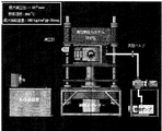
ステップ1:グリーンテープ基板(GT-1)(大きさの寸法は5×5cm2〜15×15cm2(又はそれ以上)の厚さは600〜1200μm)を5 ×5 cm2または適当なサイズの型に入れて、「真空熱圧焼結システム(略してVHPS)(図2)」に送り、真空(<1×10⁻³ torr)・熱圧(温度<500℃、圧力は最大1,152MPa(1.68×10⁵psi)に達する (調整可能タイプ))による処理をする。この方法によって作り出した高密度のグリーンテープ基板(GT-2と呼ばれる)をPychrometerで測ると、そのグリーンテープの密度は、該当セラミック酸化物の理論的密度の70%に向上することが分かる。
(2) Manufacturing method of electrode ceramic substrate:
Step 1: Green tape substrate (GT-1) (size is 5 x 5cm 2 to 15 x 15cm 2 (or more) thickness is 600 to 1200μm) 5 x 5 cm 2 or appropriate size Put it in a mold and send it to the “vacuum hot pressure sintering system (abbreviated VHPS) (Fig. 2)”, vacuum (<1 × 10 -3 torr ), hot pressure (temperature <500 ° C, pressure up to 1,152 MPa) (1.68 x 10 5 psi) (adjustable type)). When a high-density green tape substrate (called GT-2) created by this method is measured with Pychrometer, the density of the green tape is increased to 70% of the theoretical density of the corresponding ceramic oxide.
ステップ2:必要により、GT-2の表面整理はラミネート装置によって再度積層工程を加える。このLMとVHPSとの二つのシステムが交互にグリーンシート基板を強化させる方法を「新相乗的プロセス(A Novel Synergistic Process)」と称し、最終的にGT-Fというグリーンシート基板を形成する。 Step 2: If necessary, the surface preparation of GT-2 is repeated with the laminating device. The method by which the two systems of LM and VHPS alternately strengthen the green sheet substrate is called “A Novel Synergistic Process”, and finally the green sheet substrate called GT-F is formed.
ステップ3:GT-Fを酸化ジルコニウム基板で上下両方から挟持して(サンドイッチ構造)固定させ、セッターが酸化アルミナから成る高温炉(1700℃に上がれる)で二段階に循環して焼結する。第一循環の温度調節は:室温→200℃(4Hr) →450℃(2Hr) →750℃(2Hr) →1250℃ (6Hr) →室温となり、第二循環の温度調節は:室温→1400℃(4Hr)→室温となる。二段階で循環する温度昇降の速度率は1℃/min(3 ℃/min以内は最善)に保ちつつ,同時に適量の空気を導入する。第一循環は、仮焼によって全ての有機添加剤を除去する。第二循環は、焼結によって緻密化させてセラミック基板を形成する。完成された電極基板は、以下AS-1と称し、焼結の密度・機械的強度・間隙率・微細構造などの特性を評価する。このようにして形成したAS-1電極基板は、高機械的強度及び平坦度や適度な間隙率や気体通過率を備え、SOFC-MEA電極構造の基本的要件を満たしている。 Step 3: GT-F is sandwiched and fixed on both sides by a zirconium oxide substrate (sandwich structure), and the setter is circulated and sintered in two stages in a high temperature furnace (up to 1700 ° C) made of alumina oxide. Temperature control of the first circulation: room temperature → 200 ° C (4Hr) → 450 ° C (2Hr) → 750 ° C (2Hr) → 1250 ° C (6Hr) → room temperature, temperature control of the second circulation: room temperature → 1400 ° C ( 4Hr) → room temperature. While maintaining the rate of temperature rise and fall circulating in two stages at 1 ° C / min (best within 3 ° C / min), introduce an appropriate amount of air at the same time. The first circulation removes all organic additives by calcination. The second circulation is densified by sintering to form a ceramic substrate. The completed electrode substrate is hereinafter referred to as AS-1, and the characteristics such as sintering density, mechanical strength, porosity, and microstructure are evaluated. The AS-1 electrode substrate thus formed has high mechanical strength and flatness, an appropriate porosity and gas passage rate, and satisfies the basic requirements of the SOFC-MEA electrode structure.
ステップ4:AS-1をシルクスクリーン(Screen Printing)/スバッタリングコーティング(Sputtering Coating)/スビンコーティング(Spin Coating)/プラズマスプレー(Plasma Spray)などの設備及び方法で適当な厚さ(<10μm)の最適電解質(8YSZ)層を塗布して、高温炉の中で焼結(1400℃/4Hr)させる。温度昇降の速度率はいずれも1℃/min。作られたSOFC-MEAの半電池は、以下AS-Hと称する。 Step 4: Suitable thickness (<10μm) for AS-1 with equipment and methods such as Silk Screen (Screen Printing) / Sputtering Coating / Spin Coating / Plasma Spray Apply an optimal electrolyte (8YSZ) layer and sinter (1400 ℃ / 4Hr) in a high temperature furnace. The rate of temperature increase / decrease is 1 ℃ / min. The manufactured SOFC-MEA half-cell is hereinafter referred to as AS-H.
ステップ5:AS-H半電池をシルクスクリーン技術により、YSZ層の上にLSM(又はLSCFなどの材料)陰極層を塗布し、厚さ30〜50μmとして高温炉の中で焼結させる。温度昇降の速度率は、いずれも1℃/min(3 ℃/minより小さいことが最適。)である。得られた完成品は、以下ASC-Iと称する陽極支持型電池である(又はASC型のSOFC-MEA)(詳細は図3に示す複数的/機能層を備える陽極基板(NiO+YSZ))である。 Step 5: The AS-H half-cell is coated with an LSM (or material such as LSCF) cathode layer on the YSZ layer by silk screen technology and sintered in a high temperature furnace to a thickness of 30-50 μm. The rate of temperature increase / decrease is 1 ° C / min (optimally less than 3 ° C / min). The obtained finished product is an anode-supported battery, hereinafter referred to as ASC-I (or ASC-type SOFC-MEA) (for details, an anode substrate (NiO + YSZ) having plural / functional layers shown in FIG. 3). .
上記方法によれば、陽極支持セルタイプのSOFC電池は水素・ガス・炭水化物など多様の燃料をエネルギー源として直接電力に転化して電力供給に出力する。
以下、本発明を実施例に基づいて具体的に説明する。
According to the above method, the anode-supported cell type SOFC battery converts various fuels such as hydrogen, gas, and carbohydrates directly into electric power as an energy source and outputs it to the electric power supply.
Hereinafter, the present invention will be specifically described based on examples.
(実施例1)高機械的強度かつ最適な間隙率を備えたSOFC陽極基板と電池セルの製造。 (Example 1) Production of SOFC anode substrate and battery cell having high mechanical strength and optimum porosity.
この実施例は、高機械的強度かつ最適な間隙率を備えた平板型SOFC陽極基板を製造し、続いてSOFCの電池セルの完成品とする。当製造方法は、二段階からなる。第一の段階は(一)NiO+YSZ陽極基板グリーンシートの製造用スラリーの成分処方及び製造方法を合計して8ステップからなり、また(二)陽極セラミック基板の製造方法は合計5ステップからなる。以下、分節して説明する。 In this example, a flat plate-type SOFC anode substrate having high mechanical strength and an optimum porosity is manufactured, and then a SOFC battery cell is completed. The production method consists of two stages. The first stage consists of (1) the total component formulation and manufacturing method of the slurry for manufacturing the NiO + YSZ anode substrate green sheet, and (2) the manufacturing method of the anode ceramic substrate consists of a total of 5 steps. Hereinafter, it will be described in segments.
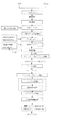
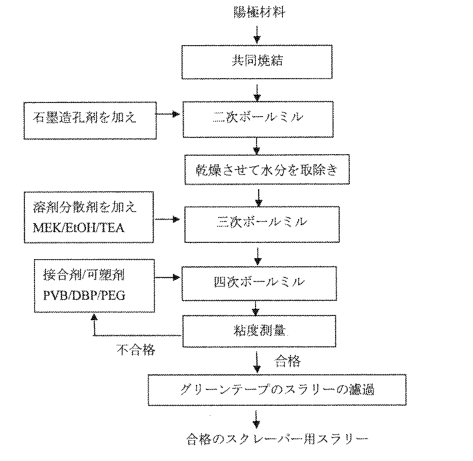
(一)NiO+8YSZ陽極基板のグリーンシート製造用スラリーの処方及び製造方法は下記の工程からなる(詳細は、図4に示す)。 (1) The formulation and manufacturing method of the slurry for manufacturing the green sheet of the NiO + 8YSZ anode substrate includes the following steps (details are shown in FIG. 4).
ステップ1:175グラムの立方晶構造(Cubic crystal structure)の8YSZを等量の酸化ニッケル(NiO)(平均の粒径は約1000 nm)と混合して、酸化ジルコニウム(ZrO2)のミルボール(約250グラム)を具えたボールミル用ボトル中に投入して、約168時間の磨砕によってNiOと8YSZを完全に混合させて、均一度の高い混合した粉体とする。その均一度はSEMでサンプル分析を行って判定する。磨砕の目標として粉体の平均粒径は300〜500 nmとし、必要に応じて適当に磨砕時間と回転速度を上げる。本項の粉体をAnode-P-1と称して、粒径/表面積比/均一度などの粉体特性については全てデータベースに保存する。 Step 1: Mix 175 grams of Cubic crystal structure 8YSZ with an equal amount of nickel oxide (NiO) (average particle size is about 1000 nm) to form zirconium oxide (ZrO2) mill balls (about 250 In a ball mill bottle with gram), and thoroughly mixed NiO and 8YSZ by grinding for about 168 hours to obtain a highly uniform mixed powder. The uniformity is determined by analyzing the sample with SEM. As a grinding target, the average particle size of the powder is 300 to 500 nm, and the grinding time and rotation speed are appropriately increased as necessary. The powder in this section is called Anode-P-1, and all the powder characteristics such as particle size / surface area ratio / uniformity are stored in the database.
ステップ2:ミルボトルから粉体Anode-P-1を取り出し、酸化ジルコニウム材質のプレート上において高温炉の中で1400 ℃/4時間の共焼結を行う。完了してから、またステップ1の磨砕工程を繰り返して、もう一回のボールミルで粉体の粒径を300〜500 nmとして均一度を高くする。この共同焼結した粉体をAnode-P-2と称する。 Anode-P-2に3.5gのサブマイクロメータ/ナノメートルの石墨粉を加えて24時間以上磨砕を繰返すことによって高均一性を確保する。こうして得られた粉はAnode-P-3と称して、総重量353.5gになる。 Step 2: Remove the powder Anode-P-1 from the mill bottle and perform co-sintering at 1400 ° C for 4 hours in a high-temperature furnace on a zirconium oxide plate. After completion, the grinding process in Step 1 is repeated, and the particle size of the powder is increased to 300 to 500 nm by another ball mill to increase the uniformity. This co-sintered powder is called Anode-P-2. High uniformity is ensured by adding 3.5g submicrometer / nanometer graphite powder to Anode-P-2 and repeating grinding for more than 24 hours. The powder thus obtained is called Anode-P-3 and has a total weight of 353.5 g.
ステップ3:Anode-P-3を353.5g採取して約100 ℃で24時間以上乾燥させ、粉体の水分と湿気を除去する。他に溶剤MEK78.1g・EtOH25.27g・及び分散剤TEA8.05gを秤量して共に酸化ジルコニウムボール(ZrO2 Ball)を具えたミルボトルに投入して24時間以上繰返し磨砕することによって高均一性を確保する。この溶剤と分散剤の均一液相は、SD溶液と称して、総重量は111.42gになる。 Step 3: Take 353.5g of Anode-P-3 and dry at about 100 ° C for more than 24 hours to remove moisture and moisture from the powder. In addition, weighed 78.1g of solvent MEK, 25.27g of EtOH and 8.05g of TEA dispersant, and put them together into a mill bottle equipped with zirconium oxide balls (ZrO2 Ball). Secure. This uniform liquid phase of the solvent and the dispersant is called SD solution and has a total weight of 111.42 g.
ステップ4:乾燥した粉体Anode-P-3をSD溶液に加え、液相で48時間以上磨砕して粉体を溶剤/分散剤に均一に分散し、溶解すると混合スラリーのSL-1となる。この時のSL-1の総重量は464.92gであった。 Step 4: Add dried powder Anode-P-3 to the SD solution and grind it in the liquid phase for 48 hours or more to disperse the powder uniformly in the solvent / dispersant. Become. The total weight of SL-1 at this time was 464.92 g.
ステップ5:可塑剤DBP4.59g、PEG4.59g及び接合剤PVB19.55gを秤量してそれぞれスラリーSL-1に加えて液相で48時間以上磨砕し、全体の完全均一化を確保し、このシート成形法に使うための陽極基板スラリーはSL-2と称して、総重量は463.65gになる。粘度計でSL-2の粘度や特性をさらにチェックして記録する。 Step 5: Weigh plasticizers DBP4.59g, PEG4.59g, and binder PVB19.55g and add them to slurry SL-1 respectively and grind in liquid phase for more than 48 hours to ensure complete homogenization of the whole. The anode substrate slurry for use in the sheet forming method is called SL-2 and has a total weight of 463.65 g. Further check and record the viscosity and properties of SL-2 with a viscometer.
ステップ6:マイクロ調整技術により、各段階ずつに適当な接合剤PVB・可塑剤DBP/PEGを加え、SL-2の粘度を150〜1500cPの間に調節する(最善の粘度は200〜500cPにある)同時に対応するグリーンシートの成形度をチェックする。この調整は、調整者の経験や技術/能力により経験的に次数と時間を決める。最後に完成した好適なスクレーパー用のスラリー(Tape
Slurry或いはSlip slurry略してSL−T)の粘度は328cPになる。(詳細は図5に示す)
Step 6: Using micro-adjustment technology, add the appropriate binder PVB / plasticizer DBP / PEG for each step and adjust the viscosity of SL-2 to between 150-1500 cP (the best viscosity is 200-500 cP) At the same time, check the forming degree of the corresponding green sheet. In this adjustment, the order and time are determined empirically by the coordinator's experience and skills / abilities. Finally, a suitable scraper slurry (Tape
The viscosity of Slurry or Slip slurry (SL-T for short) is 328 cP . (Details are shown in Fig. 5)
ステップ7:スクレーパー用スラリーSL-7は、シート成形機(Tape Casting System)で加工してグリーンシートを製造する。グリーンシートの幅は設計されたシート成形機の寸法に合わせて決められたもので、約18〜20cmとなる。単層としての厚さは、100μmで長さはAnode-P-1の粉体の加えた量によって決められる。(詳細は図6に示す)。 Step 7: Scraper slurry SL-7 is processed by a sheet molding machine (Tape Casting System) to produce a green sheet. The width of the green sheet is determined according to the dimensions of the designed sheet forming machine and is about 18 to 20 cm. The thickness as a single layer is 100 μm, and the length is determined by the amount of Anode-P-1 powder added. (Details are shown in FIG. 6).
ステップ8:カッタリングツール或いはパンチでグリーンシートを5×5cm2か10×10cm2(必要に応じてサイズと形を調整できる)大きさで厚さは100 μmの単層にカットして、12枚の単層のグリーンシートを重ねてラミネート装置(LMと言い)で積層の操作を行い、定型(正方形)で厚さは1200μmのグリーンシート基板(GT-1と呼ばれる)を製造する。ここラミネート装置の圧力は14MPa〜34MPa(2000〜5000 psi)に設定し、温度は50〜100 ℃とし、GT-1のグリーンシートの密度をPychrometerで測る。(詳細は図7に示す) Step 8: Cut the green sheet into 5 × 5cm 2 or 10 × 10cm 2 (the size and shape can be adjusted as necessary) with a cutting tool or punch into a single layer with a thickness of 100 μm. A single sheet of green sheets is stacked and laminated with a laminating machine (referred to as LM) to produce a standard (square) green sheet substrate (referred to as GT-1) with a thickness of 1200 μm. Here, the pressure of the laminating apparatus is set to 14 MPa to 34 MPa (2000 to 5000 psi), the temperature is set to 50 to 100 ° C., and the density of the green sheet of GT-1 is measured with Pychrometer. (Details are shown in Fig. 7)
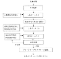
(二)陽極セラミック基板の製造方法は下記からなる。 (2) The manufacturing method of the anode ceramic substrate is as follows.
ステップ1:グリーンテープ基板GT-1(正方形の寸法は5×5cm2〜15×15cm2(又はそれ以上)厚さは600〜1200μm)を5 ×5 cm2または適当なサイズの鋳型に入れて、「真空熱圧焼結システム(略してVHPS)」に送り、真空(<1×10⁻³ torr)・熱圧(温度<500℃、圧力は最大1,152MPa(1.68×10⁵psi)に達する (調整可能タイプ))による処理をする。この方法によって作りあげた高密度のグリーンテープ基板(GT-2と呼ばれる)をPychrometerで測ると、そのグリーンテープの密度は、該当セラミック酸化物の理論的密度の70%に向上したことが分かる。
Step 1: Put green tape substrate GT-1 (square dimensions 5 x 5 cm 2 to 15 x 15 cm 2 (or more)
ステップ2:必要に応じてGT-2の表面整理は、LM機械によって再度に積層方法を行う。このLMとVHPSとの二つの工程により交互にグリーンシート基板を増強させる方法を「新相乗的プロセス(A Novel Synergistic Process)」と称し、最終的にGT-Fと称するグリーンシート基板を製造する。GT-Fのサイズは製品の要求及び熱圧金型の寸法により決められる。 Step 2: If necessary, the surface of GT-2 is laminated again by LM machine. This method of alternately reinforcing the green sheet substrate by the two processes of LM and VHPS is called “A Novel Synergistic Process”, and finally a green sheet substrate called GT-F is manufactured. The size of GT-F is determined by product requirements and hot-press mold dimensions.
ステップ3:GT-Fを酸化ジルコニウム基板で上下両方から挟持して(サンドイッチ構造)固定させ、セッターが酸化アルミナから成り高温炉(1700℃に上がれる)中で二段階に循環する焼結を行う。第一循環の温度調節は:室温→200℃(4Hr) →450℃(2Hr) →750℃(2Hr) →1250 (6Hr) →室温となり、第二循環の温度調節は:室温→1400℃(4Hr)→室温となる。二段階の循環の温度昇降の速度率は1℃/min(3 ℃/min以内が最適。)に保ちつつ,同時に適量の空気を通らせる。製造に完成された電極基板はAS-1と称し、その特性についての判定評価は、表3に示す。
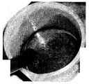
こうして得られたAS-1電極基板は、高機械的強度と平坦度及び適度な間隙率と気体通過率を具え、SOFC-MEA陽極構造の基的本要件を満たしている。(詳細は図9に示す) The AS-1 electrode substrate thus obtained has high mechanical strength, flatness, moderate porosity and gas passage rate, and satisfies the basic requirements of the SOFC-MEA anode structure. (Details are shown in Fig. 9)
ステップ4:陽極基板AS-1をシルクスクリーン(Screen Printing)の設備及び方法で厚さ約10μmの電解質(材料8YSZ)層を塗布して、1700 ℃の高温炉中で1400℃/4Hrで焼結する。温度昇降の速度率はいずれも1℃/minである。こうして作られたSOFC-MEAの半電池は、AS-Hと称する。 Step 4: Apply an electrolyte (material 8YSZ) layer with a thickness of about 10μm to the anode substrate AS-1 using screen printing equipment and method, and sinter at 1400 ℃ / 4Hr in a high temperature furnace at 1700 ℃. To do. The rate of temperature increase / decrease is 1 ° C / min. The SOFC-MEA half-cell made in this way is called AS-H.
ステップ5:AS-H半電池をシルクスクリーン技術によって、YSZ層の上に厚さ40μm のLSM陰極層を塗布して全電池を形成し、AS-WCと称する。更にAS-WCを高温炉中で焼結を行う。(1200 ℃/3 hrs)、温度昇降の速度率はいずれも1℃/minでSOFC-MEAの完成品となり、AS-C-Iと称する(詳細は図10に参照)。これが完成した陽極支持電池(又はASC型のSOFC-MEAと称する。)である。このASC-Iは、簡易電流システムで電気測定するとその電力輸出密度は32 mW/cm2に上昇する(測定面積はπcm2で温度 は 900 ℃)。また、4 X 4 cm2で測定すると、その電力輸出密度は350 mW/cm2(温度800 ℃)を超える(原型MEAは最適化した製品ではない。)。
Step 5: The AS-H half-cell is coated with an LSM cathode layer with a thickness of 40 μm on the YSZ layer by silk screen technology to form an entire cell, which is referred to as AS-WC. Furthermore, AS-WC is sintered in a high-temperature furnace. (1200 ° C / 3 hrs), the rate of temperature increase / decrease is 1 ° C / min, and the SOFC-MEA is completed as AS-CI (see Figure 10 for details). This is the completed anode-supported battery (or called ASC type SOFC-MEA). The electrical export density of ASC-I increases to 32 mW / cm 2 when measured with a simple current system (measurement area is πcm 2 and temperature is 900 ° C). Also, when measured at 4 X 4 cm 2 , its power export density exceeds 350 mW / cm 2 (
Claims (15)
A.電極基板グリーンシート製造用スラリー製造工程、及びB.電極グリーンシート基板及び電極セラミック基板の製造工程からなり、
A.電極基板グリーンシートの製造用スラリー製造工程は、
(a) セラミック粉体を、陽極基板材料としてNi+8YSZを、電解質材料として8YSZを磨砕して粉体の粒径サイズを均一化し、
(b) 上記粉体を高温オーブン中で共焼結し、室温下で造孔剤を加えて磨砕して均一化して乾燥粉体とし、
(c) 電解質材料を溶解するための有機溶剤としてMEKとEtOH、及び分散剤としてTEAを混合してボールミルで磨砕して均一化した液相とし、
(d) 上記液相に(b)の乾燥粉体を加えて磨砕して、粉体が液相中に均一に分散したスラリーとし、
(e) 上記スラリーに可塑剤としてDBPとPEG及び接合材としてPVBを加え、磨砕して均一化し、
(f) さらに、上記ステップにおける接合剤及び可塑剤を少量添加して後工程のシート形成に適した粘度に微調整し、
(g) 上記スラリーからシート形成機によってグリーンシートを形成し、
(h) 上記シートに対して、サイズを整え、或いは必要に応じて積層して厚さを調整したグリーンシートとし
B.電解質或いは電極セラミック基板の製造方法は、
(i) 上記グリーンシートを金型中で真空熱圧焼結システム(VHPS)により、1×10⁻³torr以下の真空中で、熱圧(500℃以下で最大圧力1,152MPa(1.68×10⁵psi)処理により、高密度グリーンシート(HDGS)とし、
(j) 上記高密度グリーンシート(HDGS)を積層する工程と真空熱圧焼結する工程とを交互に行う「新相乗プロセス」(A Novel Synergistic Process)により構造を強化した「高度整合性グリーンシート(HIGS)」とし
(k) 上記「高度整合性グリーンシート(HIGS)」をセラミック基板で挟持して固定し、第一段階として有機溶剤及び造孔剤を除去する仮焼を行い、第二段階として温度を上げて1700℃以上で焼結して高密度化したHICS(High Integrity Ceramic Substrate)とし、
(l) 上記セラミック基板に対して、被膜形成法のシルクスクリーン(Screen
Printing)、スパッタリングコーティング(Sputtering Coating)、スピンコーティング(Spin Coating)、又はプラズマスプレー(Plasma Spraying)によって電解質層(HICSが陽極セラミック基板である場合)或いは電極層(HICSが電解質セラミック基板である場合)を塗布し、高温炉中で焼結してSOFC-MEAの半電池(HC:Half
Cell)を形成し、
(m) 上記半電池(HC)に対して、薄膜製作技術のシルクスクリーン、スパッタリング、スピンコーティング、プラズマスプレー、又はスラリースプレー(Slurry Spray)により電解質層上にLSM又はLSCFの陰極層を塗布し、高温炉中で焼結して「高度整合性固体酸化物形燃料電池用膜電極接合体(電池セル)」(SOFC-MEA(Unit Cell))とする、
各工程からなることを特徴とする固体酸化物形燃料電池用膜電極接合体の製造方法。 1. A method for producing a membrane electrode assembly (MEA-SOFC) for a solid oxide fuel cell, comprising:
A. A slurry production process for producing an electrode substrate green sheet; It consists of the manufacturing process of electrode green sheet substrate and electrode ceramic substrate,
A. The slurry manufacturing process for manufacturing the electrode substrate green sheet is as follows:
(a) Grind ceramic powder, Ni + 8YSZ as anode substrate material, and 8YSZ as electrolyte material to make the powder particle size uniform,
(b) The above powder is co-sintered in a high-temperature oven, added with a pore-forming agent at room temperature, and ground and homogenized to obtain a dry powder.
(c) MEK and EtOH as organic solvents for dissolving the electrolyte material, and TEA as a dispersant are mixed and ground with a ball mill to obtain a uniform liquid phase,
(d) Add the dry powder of (b) to the liquid phase and grind to make a slurry in which the powder is uniformly dispersed in the liquid phase,
(e) Add DBP and PEG as plasticizers and PVB as a bonding agent to the above slurry, grind and homogenize,
(f) Furthermore, a small amount of the bonding agent and plasticizer in the above step is added to finely adjust the viscosity to be suitable for the sheet formation in the subsequent process,
(g) forming a green sheet from the slurry by a sheet forming machine,
(h) A green sheet that is adjusted in size with respect to the above sheet or laminated as necessary to adjust the thickness. The method of manufacturing the electrolyte or electrode ceramic substrate is as follows:
(i) The above green sheet is heated in a mold by a vacuum hot pressure sintering system (VHPS) in a vacuum of 1 × 10 −3 torr or less under a heat pressure (500 ° C. or less and a maximum pressure of 1,152 MPa (1.68 × 10 5 psi) processing to produce high density green sheets (HDGS)
(j) “Highly Consistent Green Sheet” whose structure has been reinforced by “A Novel Synergistic Process” which alternately performs the process of laminating the above high-density green sheets (HDGS) and the process of vacuum hot-pressure sintering (HIGS) "
(k) The above “Highly Consistent Green Sheet (HIGS)” is sandwiched and fixed by a ceramic substrate, calcined to remove the organic solvent and pore former as the first step, and raised in temperature as the second step. HICS (High Integrity Ceramic Substrate) is sintered at 1700 ° C or higher and densified.
(l) A film-forming silk screen (Screen)
Printing, Sputtering Coating, Spin Coating, Plasma Spraying, Electrolyte Layer (if HICS is an Anode Ceramic Substrate) or Electrode Layer (if HICS is an Electrolytic Ceramic Substrate) Applied and sintered in a high-temperature furnace to make a SOFC-MEA half-cell (HC: Half
Cell),
(m) Applying a cathode layer of LSM or LSCF on the electrolyte layer to the above half-cell (HC) by silk screen, sputtering, spin coating, plasma spray, or slurry spray of thin film fabrication technology, Sintered in a high-temperature furnace to form a highly compatible solid oxide fuel cell membrane electrode assembly (battery cell) (SOFC-MEA (Unit Cell))
A method for producing a membrane electrode assembly for a solid oxide fuel cell, comprising each step.
工程(b)の造孔剤としてグラファイトを陽極材料に対して0.1〜10wt%、とし、
工程(c)の有機溶剤としてMEKを12〜22wt%、とEtOHを5〜9wt%、及び分散剤としてTEAを1〜2wt%とし、
工程(e)の可塑剤としてDBPを0.5〜2.0wt%、とPEGを0.5〜2.0wt%、及び接合材としてPVBを3〜6wt%、
を加えることを特徴とする請求項1に記載の固体酸化物形燃料電池用膜電極接合体の製造方法。 NiO + 8YSZ is 50 to 86 wt% as the anode substrate material in the step (a), and 8YSZ is 50 to 86 wt% as the electrolyte material, and NiO is 35 to 65 wt% of the total weight of NiO + 8YSZ,
As a pore-forming agent in the step (b), graphite is 0.1 to 10 wt% with respect to the anode material,
MEK as the organic solvent in step (c) is 12 to 22 wt%, EtOH is 5 to 9 wt%, and TEA is 1 to 2 wt% as the dispersant,
0.5 to 2.0 wt% DBP as a plasticizer in step (e), 0.5 to 2.0 wt% PEG, and 3 to 6 wt% PVB as a bonding material,
2. The method for producing a membrane electrode assembly for a solid oxide fuel cell according to claim 1, wherein:
室温→200℃(4Hr) →450℃(2Hr) →750℃(2Hr) →1250℃ (6Hr) →室温であり、第二段階の焼結過程の温度条件は:
室温→1400℃(4Hr)→室温であり、二段階とも焼結過程の温度昇降の速度率は1℃/min(但し3 ℃/min以下が好適。)であることを特徴とする請求項1に記載の固体酸化物形燃料電池用膜電極接合体の製造方法。 The temperature condition of the sintering process of the first stage of the above step k is:
Room temperature → 200 ° C (4Hr) → 450 ° C (2Hr) → 750 ° C (2Hr) → 1250 ° C (6Hr) → room temperature.The temperature conditions for the second stage sintering process are:
2. Room temperature → 1400 ° C. (4Hr) → Room temperature, and the rate of temperature increase / decrease in the sintering process in both stages is 1 ° C./min (however, 3 ° C./min or less is preferable). A process for producing a membrane electrode assembly for a solid oxide fuel cell as described in 1 above.
The material and thickness of the cathode layer in step m above are LSM / LSCF and 30-50 μm, respectively, and the sintering temperature control procedure is room temperature → 1200 ° C./3 hrs → room temperature, and the rate of temperature rise / fall is 3 ° C. / 2. The method for producing a membrane electrode assembly for a solid oxide fuel cell according to claim 1, wherein the membrane electrode assembly is min or less .
Priority Applications (1)
| Application Number | Priority Date | Filing Date | Title |
|---|---|---|---|
| JP2007258023A JP5099892B2 (en) | 2007-10-01 | 2007-10-01 | Manufacturing method of membrane electrode assembly for highly consistent solid oxide fuel cell |
Applications Claiming Priority (1)
| Application Number | Priority Date | Filing Date | Title |
|---|---|---|---|
| JP2007258023A JP5099892B2 (en) | 2007-10-01 | 2007-10-01 | Manufacturing method of membrane electrode assembly for highly consistent solid oxide fuel cell |
Publications (2)
| Publication Number | Publication Date |
|---|---|
| JP2009087829A JP2009087829A (en) | 2009-04-23 |
| JP5099892B2 true JP5099892B2 (en) | 2012-12-19 |
Family
ID=40660968
Family Applications (1)
| Application Number | Title | Priority Date | Filing Date |
|---|---|---|---|
| JP2007258023A Active JP5099892B2 (en) | 2007-10-01 | 2007-10-01 | Manufacturing method of membrane electrode assembly for highly consistent solid oxide fuel cell |
Country Status (1)
| Country | Link |
|---|---|
| JP (1) | JP5099892B2 (en) |
Families Citing this family (5)
| Publication number | Priority date | Publication date | Assignee | Title |
|---|---|---|---|---|
| KR101150836B1 (en) | 2009-10-30 | 2012-06-13 | 한국전력공사 | The structure of solid oxide fuel cell and manufacturing method thereof |
| CN102689492B (en) * | 2012-06-12 | 2014-10-01 | 北京合能阳光新能源技术有限公司 | Production process for producing PVB (Polyvinyl Butyral) laminated glass cell component by using improved laminating machine |
| JP6225450B2 (en) * | 2013-03-28 | 2017-11-08 | 凸版印刷株式会社 | Membrane electrode assembly and polymer electrolyte fuel cell |
| US11349135B2 (en) * | 2020-08-03 | 2022-05-31 | Institute Of Nuclear Energy Research, Atomic Energy Council, Executive Yuan | Method of preparation and application for glass ceramic sealing thin strips |
| CN112708301A (en) * | 2021-01-06 | 2021-04-27 | 闽南理工学院 | Preparation method of nano 8YSZ aqueous phase suspension with stable dispersion |
Family Cites Families (6)
| Publication number | Priority date | Publication date | Assignee | Title |
|---|---|---|---|---|
| JPH07320754A (en) * | 1994-05-23 | 1995-12-08 | Toto Ltd | Connecting structure between solid electrolytic film and electrode film, and its manufacture |
| JPH08287926A (en) * | 1995-04-17 | 1996-11-01 | Nippon Telegr & Teleph Corp <Ntt> | Manufacture of solid electrolyte fuel cell |
| JP2000353530A (en) * | 1999-04-08 | 2000-12-19 | Toto Ltd | MANUFACTURE OF NiO AND/OR Ni/YSZ COMPOSITE POWDER AND MANUFACTURE OF SOLID ELECTROLYTE FUEL CELL USING THEREOF |
| US7638222B2 (en) * | 2001-03-28 | 2009-12-29 | Hexis Ag | Porous, gas permeable layer substructure for a thin, gas tight layer for use as a functional component in high temperature fuel cells |
| JP4559068B2 (en) * | 2003-12-26 | 2010-10-06 | 日本特殊陶業株式会社 | Method for producing solid oxide fuel cell |
| JP2007242429A (en) * | 2006-03-09 | 2007-09-20 | Nissan Motor Co Ltd | Solid oxide fuel cell and its manufacturing method |
-
2007
- 2007-10-01 JP JP2007258023A patent/JP5099892B2/en active Active
Also Published As
| Publication number | Publication date |
|---|---|
| JP2009087829A (en) | 2009-04-23 |
Similar Documents
| Publication | Publication Date | Title |
|---|---|---|
| Wei et al. | A novel fabrication of yttria-stabilized-zirconia dense electrolyte for solid oxide fuel cells by 3D printing technique | |
| US7914636B2 (en) | Synergistic process and recipe for fabrication of a high integrity membrane electrode assembly of solid oxide fuel cell | |
| CN107210469B (en) | Method of forming an electrolyte | |
| Shen et al. | Co-sintering anode and Y2O3 stabilized ZrO2 thin electrolyte film for solid oxide fuel cell fabricated by co-tape casting | |
| CN107223289B (en) | Method of forming an electrolyte | |
| JP5099892B2 (en) | Manufacturing method of membrane electrode assembly for highly consistent solid oxide fuel cell | |
| JP2015509277A (en) | Design and manufacturing technology for solid oxide fuel cells with improved output performance in medium and low temperature operation | |
| Misono et al. | Ni-SDC cermet anode fabricated from NiO–SDC composite powder for intermediate temperature SOFC | |
| EP2045858B1 (en) | A novel synergistic process and recipe for fabrication of a high integrity membrane electrode assembly of solid oxide fuel cell | |
| KR101218980B1 (en) | Electrode material for fuel cell, fuel cell comprising the same and a method for manufacturing the same | |
| KR102247782B1 (en) | A manufacturing method of solid oxide fuel cell via calendering process | |
| JP5198908B2 (en) | A method for producing a completely dense electrolyte layer laminated on a high performance solid oxide fuel cell membrane electrode assembly (SOFC-MEA). | |
| KR102582304B1 (en) | Method of manufacturing a solid oxide fuel cell including a multi-layered electrolyte layer using a calendering process | |
| Mohebbi et al. | The Effect of Process Parameters on the Apparent Defects of Tape-Cast SOFC Half-Cell | |
| WO2010135416A1 (en) | Ion conducting composite electrolyte for solid state electrochemical devices | |
| KR20140046714A (en) | High ionic conductive electrolyte support and unit cell for solid oxide fuel cell | |
| WO2011036972A1 (en) | Cell of solid oxide fuel cell | |
| KR101327673B1 (en) | Granular powder for a sacrifice lubrication layer interposed between electrode and electrolyte of solid oxide fuel cell and the method for manufacturing solid oxide fuel cell using the same | |
| TW200908424A (en) | A novel synergistic process and recipe for fabrication of a high integrity membrane electrode assembly of solid oxide fuel cell | |
| Mohebbi et al. | Advanced Ceramics Progress |
Legal Events
| Date | Code | Title | Description |
|---|---|---|---|
| A621 | Written request for application examination |
Free format text: JAPANESE INTERMEDIATE CODE: A621 Effective date: 20090716 |
|
| A977 | Report on retrieval |
Free format text: JAPANESE INTERMEDIATE CODE: A971007 Effective date: 20120613 |
|
| A131 | Notification of reasons for refusal |
Free format text: JAPANESE INTERMEDIATE CODE: A131 Effective date: 20120618 |
|
| A521 | Request for written amendment filed |
Free format text: JAPANESE INTERMEDIATE CODE: A523 Effective date: 20120813 |
|
| A131 | Notification of reasons for refusal |
Free format text: JAPANESE INTERMEDIATE CODE: A131 Effective date: 20120903 |
|
| A521 | Request for written amendment filed |
Free format text: JAPANESE INTERMEDIATE CODE: A523 Effective date: 20120903 |
|
| TRDD | Decision of grant or rejection written | ||
| A01 | Written decision to grant a patent or to grant a registration (utility model) |
Free format text: JAPANESE INTERMEDIATE CODE: A01 Effective date: 20120924 |
|
| A01 | Written decision to grant a patent or to grant a registration (utility model) |
Free format text: JAPANESE INTERMEDIATE CODE: A01 |
|
| A61 | First payment of annual fees (during grant procedure) |
Free format text: JAPANESE INTERMEDIATE CODE: A61 Effective date: 20120924 |
|
| FPAY | Renewal fee payment (event date is renewal date of database) |
Free format text: PAYMENT UNTIL: 20151005 Year of fee payment: 3 |
|
| R150 | Certificate of patent or registration of utility model |
Ref document number: 5099892 Country of ref document: JP Free format text: JAPANESE INTERMEDIATE CODE: R150 Free format text: JAPANESE INTERMEDIATE CODE: R150 |
|
| R250 | Receipt of annual fees |
Free format text: JAPANESE INTERMEDIATE CODE: R250 |
|
| R250 | Receipt of annual fees |
Free format text: JAPANESE INTERMEDIATE CODE: R250 |
|
| R250 | Receipt of annual fees |
Free format text: JAPANESE INTERMEDIATE CODE: R250 |
|
| R250 | Receipt of annual fees |
Free format text: JAPANESE INTERMEDIATE CODE: R250 |
|
| R250 | Receipt of annual fees |
Free format text: JAPANESE INTERMEDIATE CODE: R250 |
|
| R250 | Receipt of annual fees |
Free format text: JAPANESE INTERMEDIATE CODE: R250 |
|
| R250 | Receipt of annual fees |
Free format text: JAPANESE INTERMEDIATE CODE: R250 |
|
| R250 | Receipt of annual fees |
Free format text: JAPANESE INTERMEDIATE CODE: R250 |
|
| R250 | Receipt of annual fees |
Free format text: JAPANESE INTERMEDIATE CODE: R250 |