JP5099180B2 - Information decoding apparatus, information decoding method, and program - Google Patents
Information decoding apparatus, information decoding method, and program Download PDFInfo
- Publication number
- JP5099180B2 JP5099180B2 JP2010142131A JP2010142131A JP5099180B2 JP 5099180 B2 JP5099180 B2 JP 5099180B2 JP 2010142131 A JP2010142131 A JP 2010142131A JP 2010142131 A JP2010142131 A JP 2010142131A JP 5099180 B2 JP5099180 B2 JP 5099180B2
- Authority
- JP
- Japan
- Prior art keywords
- information
- light receiving
- light
- display
- light emitting
- Prior art date
- Legal status (The legal status is an assumption and is not a legal conclusion. Google has not performed a legal analysis and makes no representation as to the accuracy of the status listed.)
- Active
Links
Images


Description
本発明は、光を伝送媒体として情報を送受信する情報伝送システムに適用される情報復号装置、情報復号方法、及び、プログラムに関する。 The present invention relates to an information decoding apparatus, an information decoding method, and a program applied to an information transmission system that transmits and receives information using light as a transmission medium.
従来より、可視光通信技術を用いることによる情報伝送システムが考案されている。例えば、情報復号装置としてデジタルカメラを用い、画角に存在する発光ユニットを連続的に撮像することにより、この発光ユニットが発光した輝点の点滅から情報を復号して、撮像された画像上の輝点の位置に吹き出しなどの図形と情報とを表示するシステムが考案されている(例えば特許文献参照)。 Conventionally, an information transmission system using a visible light communication technique has been devised. For example, a digital camera is used as an information decoding device, and by continuously capturing images of light emitting units present at the angle of view, information is decoded from blinking bright spots emitted by the light emitting units, and on the captured image. A system for displaying a graphic such as a balloon and information at the position of a bright spot has been devised (see, for example, Patent Document).
しかしながら、上記の技術においては、例えば、画角内に同じ情報に基づく輝点が複数存在した場合、夫々の輝点の位置に対応して吹き出しなどの図形と情報とを表示させるため、発光ユニットを敷設する側では、受信側の端末に対し、単一の情報を面表示等で出力させることは不可能だった。 However, in the above technology, for example, when there are a plurality of bright spots based on the same information in the angle of view, a light emitting unit is displayed in order to display a figure and information such as a balloon corresponding to the position of each bright spot. It is impossible for the receiving side to output a single piece of information to the receiving side terminal in a plane display or the like.
本発明はこのような問題点に鑑みてなされたものであり、光を伝送媒体として情報を送受信する技術において、より表現力の豊かな情報の報知を可能とすることを目的とする。 The present invention has been made in view of such problems, and an object of the present invention is to make it possible to report information with more expressiveness in a technique for transmitting and receiving information using light as a transmission medium.
上記目的を達成するため、請求項1記載の発明は、外部に存在し、情報を時間的な光の変化に変調させて発光する複数の発光装置による発光を連続して受光する規則的に二次元配列された複数の受光素子からなる受光手段と、この受光手段が受光した光の変化から情報を夫々復号する復号手段と、この復号手段によって夫々復号された情報に含まれる共通情報と、前記複数の発光装置が発光した前記時間的な変化を有する光の前記受光手段における受光位置と、を対応付けて複数組記憶する記憶手段と、前記記憶手段が、更に境界線情報を複数記憶したか否かを判断する第1の判断手段と、この第1の判断手段により更に境界線情報を記憶したと判断すると、これら境界線情報が記憶された受光位置を線で結ぶように表示する表示手段と、を備えることを特徴とする。
In order to achieve the above-mentioned object, the invention described in
また、請求項2記載の発明は、上記請求項1記載の発明において、前記表示手段は、前記受光位置のうち前記境界線情報が記憶された複数の受光位置について線で結ぶとともに、前記境界線情報が記憶されていない受光位置がある場合はこの線で囲まれた領域の広がりの方向を示す情報を前記境界線情報が記憶されていない受光位置に向けて表示することを特徴とする。 According to a second aspect of the present invention, in the first aspect of the present invention, the display unit connects the plurality of light receiving positions where the boundary line information is stored among the light receiving positions with lines, and the boundary line. When there is a light receiving position where no information is stored, information indicating the direction of expansion of the region surrounded by the line is displayed toward the light receiving position where the boundary line information is not stored .
また、請求項3記載の発明は、上記請求項1又は2記載の発明において、前記記憶手段が、境界線情報に加え順番情報を記憶したか否かを判断する第2の判断手段を更に備え、前記表示手段は、前記記憶手段によって記憶された受光位置のうち、前記境界線情報が記憶された受光位置について前記順番情報に沿って線で結ぶように表示することを特徴とする。
The invention described in
また、請求項4記載の発明は、上記請求項3記載の発明において、前記表示手段は、前記境界線情報が記憶された受光位置について前記順番情報に沿って線で結ぶとともに、前記順番情報において順番が飛んでいる受光位置については、この線で結ぶことなく、共に同じ領域の受光位置であることを示す情報を表示することを特徴とする。 According to a fourth aspect of the present invention, in the invention according to the third aspect, the display means connects the light receiving position where the boundary line information is stored with a line along the order information. The light receiving positions that are out of order are characterized by displaying information indicating that they are light receiving positions in the same region without being connected by this line .
また、請求項5記載の発明は、上記請求項1乃至4の何れかに記載の発明において、前記共通情報は前記境界線情報で囲まれる範囲に共通する第1の表示情報を含み、前記表示手段は、前記境界線情報が記憶された受光位置を線で結び、且つ、その境界線で囲まれた範囲に前記第1の表示情報を表示することを特徴とする。
The invention according to
また、請求項6記載の発明は、上記請求項1乃至5の何れかに記載の発明において、前記記憶手段が、前記共通情報に加え前記複数の発光装置に個別に設定された第2の表示情報を記憶したか否かを判断する第3の判断手段を更に備え、前記表示手段は、前記記憶された受光位置のうち、前記第2の表示情報が記憶された受光位置についてその受光位置の近くに前記第2の表示情報を表示することを特徴とする。 According to a sixth aspect of the present invention, in the invention according to any one of the first to fifth aspects, the storage means is a second display individually set in the plurality of light emitting devices in addition to the common information. And further comprising a third determining means for determining whether or not the information is stored, wherein the display means includes a light receiving position of the stored light receiving position for the light receiving position where the second display information is stored. The second display information is displayed nearby .
上記目的を達成するため、請求項7記載の発明は、規則的に二次元配列された複数の受光素子を備える受光部にて、外部に存在し、情報を時間的な光の変化に変調させて発光する複数の発光装置による発光を連続して受光させる受光ステップと、この受光ステップにて受光された光の変化から情報を夫々復号する復号ステップと、この復号ステップにて夫々復号された情報に含まれる共通情報と、前記複数の発光装置が発光した前記時間的な変化を有する光の前記受光部における受光位置と、を対応付けて複数組記憶させる記憶ステップと、前記記憶ステップにて更に境界線情報を複数記憶したか否かを判断する判断ステップと、この判断ステップにて更に境界線情報を記憶したと判断すると、これら境界線情報が記憶された受光位置を線で結ぶように表示させる表示ステップと、を含むことを特徴とする。 In order to achieve the above object, the invention according to claim 7 is a light receiving unit including a plurality of light receiving elements regularly arranged in a two-dimensional array, and exists outside and modulates information into temporal light changes. A light receiving step for continuously receiving light emitted by a plurality of light emitting devices that emit light, a decoding step for decoding information from changes in light received at the light receiving step, and information decoded at the decoding step, respectively. A storage step of storing a plurality of sets of the common information included in the light-receiving portions of the light having the temporal change emitted by the plurality of light-emitting devices in association with each other, and further storing in the storage step If it is determined that a plurality of boundary line information is stored, and if it is determined that the boundary line information is further stored in this determination step, the light receiving position where these boundary line information is stored is represented by a line. Characterized by comprising a display step of displaying the dance, the.
上記目的を達成するため、請求項8記載の発明は、規則的に二次元配列された複数の受光素子を備える受光部を備える情報復号装置が備えるコンピュータを、外部に存在し、情報を時間的な光の変化に変調させて発光する複数の発光装置による発光を連続して受光させる受光手段、この受光手段によって受光された光の変化から情報を夫々復号する復号手段、この復号手段によって夫々復号された情報に含まれる共通情報と、前記複数の発光装置が発光した前記時間的な変化を有する光の前記受光部における受光位置と、を対応付けて複数組記憶させる記憶手段、前記記憶手段によって更に境界線情報を複数記憶したか否かを判断する判断手段、この判断手段によって更に境界線情報を記憶したと判断すると、これら境界線情報が記憶された受光位置を線で結ぶように表示させる表示手段、として機能させることを特徴とする。
In order to achieve the above-mentioned object, the invention according to
本発明によれば、光を伝送媒体として情報を送受信する技術において、より表現力の豊かな情報の報知を可能となる。 ADVANTAGE OF THE INVENTION According to this invention, in the technique which transmits / receives information using light as a transmission medium, the alerting | reporting of information with richer expressiveness is attained.
(第1の実施の形態)
以下、本発明の第1の実施形態を、図面を参照しながら説明する。なお、以下の説明における様々な細部の特定ないし実例および数値や文字列その他の記号の例示は、本発明の思想を明瞭にするための、あくまでも参考であって、それらのすべてまたは一部によって本発明の思想が限定されないことは明らかである。また、周知の手法、周知の手順、周知のアーキテクチャおよび周知の回路構成等(以下「周知事項」)についてはその細部にわたる説明を避けるが、これも説明を簡潔にするためであって、これら周知事項のすべてまたは一部を意図的に排除するものではない。かかる周知事項は本発明の出願時点で当業者の知り得るところであるので、以下の説明に当然含まれている。
(First embodiment)
DESCRIPTION OF EXEMPLARY EMBODIMENTS Hereinafter, a first embodiment of the invention will be described with reference to the drawings. It should be noted that the specific details or examples in the following description and the illustrations of numerical values, character strings, and other symbols are only for reference in order to clarify the idea of the present invention, and the present invention may be used in whole or in part. Obviously, the idea of the invention is not limited. In addition, a well-known technique, a well-known procedure, a well-known architecture, a well-known circuit configuration, and the like (hereinafter, “well-known matter”) are not described in detail, but this is also to simplify the description. Not all or part of the matter is intentionally excluded. Such well-known matters are known to those skilled in the art at the time of filing of the present invention, and are naturally included in the following description.
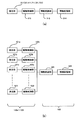
図1は、本実施形態における利用形態を示す図であり、都市の情景を簡略的に表現したものである。同図において、都市は、道路500、600で区切られた、区画100、200、300、400からなる。またこれらの区画のうち、区画100には野球場110を含む公園が存在し、区画200はビル210と220とが、区画400はビル410が夫々建造されている。更に、遠景700には、塔の形状を模した建造物710、ビル720、730が存在する。
FIG. 1 is a diagram showing a usage pattern in the present embodiment, which is a simplified representation of a city scene. In the figure, a city is composed of
区画100には、発光部121a〜121lが設けられた街灯120a〜120lが上記公園を囲むように敷設されるとともに、これらの発光部の発光駆動を制御する施設122が存在する。また、ビル210、220、410、720、及び、730には発光部211、221、411、721、及び、731が敷設され、建造物710にも発光部711が備えられている。800は情報復号装置としてのデジタルカメラであり、本実施の形態は、デジタルカメラ800の操作者が当該都市を俯瞰撮影する場合について述べるものである。
In the
発光部121a〜121l、211、221、411、711、721、及び、731は、照明や飛翔体に対して自己位置を識別させるための用途の他、時間的に輝度変化するように発光駆動することにより可視光通信システムにおける情報送信装置としての用途も有するが、詳細については、特開2003−179556号公報において述べられているので省略する。
The
図2(a)は、発光部211、221、411、711、721、及び、731を含む発光装置の機能構成を示す図である。同図において、発光装置は、発光部221(221、411、711、721、及び、731)、駆動制御部212、情報変調部213、及び、情報記憶部214とを含む。
FIG. 2A is a diagram illustrating a functional configuration of the light emitting device including the
発光部221(221、411、711、721、及び、731)はLED等の発光デバイスで構成されている。情報記憶部214は情報復号装置へ伝送すべき情報を記憶する。典型的にはこの発光部221(221、411、711、721、及び、731)が備えられた建造物の名称、敷設された階数、フロア情報、及び、その建造物若しくはその階(フロア)で催されているイベント等、コマーシャル的な要素を含む表示情報をデジタルデータとして記憶する。情報変調部213は、情報記憶部214に記憶されたデジタルデータを時間的に輝度変化する情報に符号化、及び、変調するための回路部である。符号化方式、及び、変調方式については任意ではあるが、望ましくは周波数を28.8(kHz)とする副搬送波(サブキャリア)を採用した4PPM(Pulse−position modulation)を採用する。
The light emitting unit 221 (221, 411, 711, 721, and 731) is composed of a light emitting device such as an LED. The
駆動制御部212は情報変調部213にて変調されたデータに従って、発光部221(221、411、711、721、及び、731)を例えば、規格化された可視光通信システムで伝送可能な周期で点滅駆動させる等、時間的に輝度が変化するように駆動制御する回路部である。尚、発光部221(221、411、711、721、及び、731)に接続されるこれらの回路部は、敷設されているビル210、220、410、720、730、及び、建造物710の内部に備えられている。
In accordance with the data modulated by the
図2(b)は、発光部121a〜121lを含む発光装置の機能構成を示す図である。同図において、発光装置は、発光部121a〜121l、駆動制御部123a〜123l、情報変調部124、及び、情報記憶部125とを含む。
発光部121a〜121lはLED等の発光デバイスで構成されている。情報記憶部125は情報復号装置へ伝送すべき情報を記憶する。この情報記憶部125に格納される情報は詳細には図3にて示すように、発光部121a〜121lに個別に設定される光源ユニークID情報901と、発光部121a〜121lに共通に設定される案内ポイントID情報902と、表示情報903とで構成されている。尚、表示情報903については、発光部121a〜121lが敷設された街灯120a〜120lで囲まれる区画の施設(本実施の形態では公園)の名称、及び、その施設で催されているイベント等、コマーシャル的な要素を含む表示情報をデジタルデータとして記憶する。
FIG. 2B is a diagram illustrating a functional configuration of the light emitting device including the
The
情報変調部124は、情報記憶部125に記憶されたデジタルデータを時間的に輝度変化する情報に符号化、及び、変調するための回路部である。符号化方式、及び、変調方式については任意ではあるが、望ましくは周波数を28.8(kHz)とする副搬送波(サブキャリア)を採用した4PPM(Pulse−position modulation)を採用する。駆動制御部123a〜123l、情報変調部124にて変調されたデータに従って、発光部121a〜121lを例えば、規格化された可視光通信システムで伝送可能な周期で点滅駆動させる等、時間的に輝度が変化するように駆動制御する回路部である。尚、この発光装置の機能構成において、街灯120a〜120lは夫々が発光部121a〜121l、及び、駆動制御部123a〜123lを備え、施設122は、情報変調部124、及び、情報記憶部125を備える。そして、施設122と街灯120a〜120lとを繋ぐ伝送ケーブルを区画100に埋設する等により、施設122にて発光部121a〜121lの照明制御、変調制御、及び、情報送信のための発光タイミングの同期制御を集中管理するようになっている。
The
したがって、この区画100において、イベント等が一時的に催される場合であっても、施設122にて情報記憶部125に設定される情報を書き換えるのみで発光部121a〜121l夫々が送信する情報を制御できるので、送信すべき情報の管理が容易になる。
Therefore, even if an event or the like is temporarily held in this
図3は、上述の情報記憶部125に格納される情報を示すが、発光部121a〜121lが送信する情報のデータフォーマット900でもある。発光部121a〜121lは夫々時間的に輝度を変化させて発光することにより、このデータフォーマット900の内容を巡回的に外部の不特定多数の情報復号装置に送信する。
FIG. 3 shows information stored in the
図4は、デジタルカメラ800の概念的な回路構成を示す図である。同図において、デジタルカメラ800は、レンズ801、撮像部802、バッファ803、復号処理部804、画像処理部805、制御部806、プログラムメモリ807、表示部808、操作部809、画像記録部810、及び、バス811を備える。
FIG. 4 is a diagram showing a conceptual circuit configuration of the
レンズ801は、ズームレンズ、及び、フォーカスレンズからなり、操作部809からのズーム制御操作、及び、制御部806による合焦制御に基づく制御信号が入力されることにより、撮像部802が撮像する撮像画角や光学像を制御する機能を有する。
撮像部802は、規則的に二次元配列された複数の受光素子として、CCDやCMOS等の撮像デバイスで構成され、レンズ801を介して入光された光学像を、制御部806からの制御信号に基づいて所定範囲の撮像画角で撮像(受光)し、その撮像画角内の画像信号をデジタルデータに変換して、画像処理部805へ出力する。また、撮像部802は、後述の撮影モードにおいては、撮像画角内の画像を時間的に連続して撮像し、その撮像画角を連続するフレームとして画像処理部805に出力して、スルー画像として表示部808に表示するとともに、上記フレームをバッファ803に逐次出力する。
The
The
バッファ803は、記憶手段、記憶部としての座標データリスト8031を含み、制御部806からの制御信号に基づいて上記撮像部803から出力されたフレームを所定量(詳細には、少なくとも上記データフォーマット900にて送信される輝度変化された情報に相当する枚数)を一時的に蓄積する。また、上記所定量のフレーム夫々に上記発光部121a〜121l、211、221、411、711、721、及び、731の光を受光することによる「輝き」が存在する場合には、撮像画角におけるこの「輝き」が存在する受光位置(詳細には上記「輝き」を受光した撮像範囲の中心座標、以後輝点座標という)と、この座標における上記所定量のフレーム間の時間的な輝度変化の態様を、例えば点灯=「1」/消灯=「0」からなるビットデータ列として座標データリスト8031に格納し、更新する。
The
復号処理部804は、制御部806からの制御信号に基づいて、上記の座標データリスト8031に格納された上記の輝度変化の態様をデジタルデータの情報に復号する機能を有する。
画像処理部805は、制御部806からの制御信号に基づいて、撮像部802から出力されたフレーム(デジタルデータ)について、表示部808にスルー画像として表示させるべく画質や画像サイズを調整して出力させる他、操作部809からの記録指示操作に基づく制御信号が入力されると、記録指示された時点の撮像部802における撮像画角内(若しくは表示部808に表示された表示範囲内)の光学像を例えば、JPEG等の圧縮符号化方式にて符号化・ファイル化する機能を有する。
The
Based on the control signal from the
制御部806はプログラムメモリ807に記憶されたプログラムに基づいて、デジタルカメラ全体の制御を行う機能を有する。
プログラムメモリ807は、本実施の形態におけるデジタルカメラ800の動作をプログラムとして記憶し、例えば操作部809において電源投入等の操作が検出されると、制御部806がこのプログラムを読み出してロードし、各処理を実行する。
表示部808は、例えば液晶デバイス等の表示素子とこの表示素子を駆動させるドライバとを備え、画像処理部805から出力されたスルー画像を表示するとともに、復号処理部804にて復号された情報をこの情報が読み出された輝点座標と対応付けて、上述のスルー画像に重畳表示して出力報知する機能を有する。
The
The
The
操作部809は、記録指示を検出するためのシャッターキー、前記レンズ801のズームレンズを操作するためのズームキー等を備える。
画像記録部810は、画像処理部805にてファイル化された光学像を格納するとともに、復号処理部804にて復号された情報を格納する。
The
The
次に、本実施の形態のデジタルカメラ800の制御部806の処理内容を図5のフローチャートを用いて説明する。
Next, processing contents of the
まずスタート時、デジタルカメラ800が撮影モードに設定されると、制御部806は撮像部802に対し撮像画角内の画像を時間的に連続して撮像させ、その撮像画角を連続するフレームとして画像処理部805に出力させ、このフレームに対応するスルー画像を表示部808に逐次表示・更新させる。また、上記フレームをバッファ803に逐次出力させ、蓄積させる(ステップS1)。
ステップS1にてバッファ803へのフレームの蓄積が開始されると、このバッファ803が所定量のフレーム(詳細には、少なくとも上記データフォーマット900にて送信される輝度変化された情報に相当する枚数)を蓄積したか否かを判断する(ステップS2)。所定量のフレームが蓄積されたと判断したならば、ステップS3に進み、蓄積されていないと判断したならばステップS1に戻る。
First, at the start, when the
When accumulation of frames in the
ステップS2にて、バッファ803が所定量のフレームを蓄積したと判断すると、座標データリスト8031の生成を行う(ステップS3)。詳細には、上記の所定量のフレーム夫々に上記発光部121a〜121l、211、221、411、711、721、及び、731の光による輝点座標を求め、この座標における上記所定量のフレーム間の時間的な輝度変化の態様を、例えば点灯=「1」/消灯=「0」からなるビットデータ列として生成し、上述の輝点座標と対応付けた座標データリスト8031を生成する。
If it is determined in step S2 that the
ステップS3にて座標データリスト8031が生成されると、復号処理部804に対し、この座標データリスト8031から輝点座標毎に輝度変化の態様を読出させ、情報に復号させる(ステップS4)。そして、これら復号された情報において、図3に示したデータフォーマット900で送信され、同一の案内ポイントID情報902を有する輝点座標が複数存在するか否かを判断する(ステップS5)。
When the coordinate
同一の案内ポイントID情報902を有する輝点座標が複数存在すると判断した場合(ステップS5→Yes)、それら同一の案内ポイントID情報902を有する複数の輝点座標の分布状態を解析し(ステップS6)、これらを頂点とした外接多角形をスルー画像上に重畳させるように描画する(ステップS7)。そして、この描画された外接多角形の内部を半透明の特定色でハッチング処理し(ステップS8)、そのハッチング領域の中心に復号された情報(表示情報903)を重畳表示するよう制御する(ステップS9)。
If it is determined that there are a plurality of bright spot coordinates having the same guide point ID information 902 (step S5 → Yes), the distribution state of the plurality of bright spot coordinates having the same guide
一方、同一の案内ポイントID情報を有する輝点座標が複数存在しないと判断した場合(ステップS5→No)、その輝点座標からは独立した情報が送信されていると判断し、その情報を吹き出しの形状を模した画像と合成し、画像処理部805から出力されるスルー画像の対応する輝点座標に重畳表示するよう制御する(ステップS10)。
そしてステップS9、ステップS10による表示制御の後、操作部809に対する任意の操作を検出することによる当該撮影モードを抜ける旨が検出されたか否かを判断し(ステップS11)、当該撮影モードを抜ける旨が検出されたと判断すると本処理を終了させる一方(ステップS11→No)、当該撮影モードを抜ける旨が検出されたと判断すると(ステップS11→Yes)ステップS1に戻る。
On the other hand, when it is determined that there are not a plurality of bright spot coordinates having the same guide point ID information (step S5 → No), it is determined that information independent from the bright spot coordinates is transmitted, and the information is ballooned. Is combined with an image imitating the shape of the image and controlled to be superimposed and displayed on the corresponding bright spot coordinates of the through image output from the image processing unit 805 (step S10).
After the display control in steps S9 and S10, it is determined whether or not the exit from the shooting mode is detected by detecting any operation on the operation unit 809 (step S11), and the exit from the shooting mode is determined. If it is determined that the image capturing mode has been detected, the process is terminated (step S11 → No). If it is determined that exit from the shooting mode is detected (step S11 → Yes), the process returns to step S1.
図6は図5のステップS9における表示部808の表示態様を示す図である。
同図は、図1に示した「都市を俯瞰撮影した状態」を表示部808に表示させた状態を示すものであり、図1の発光部211の発光を撮像した輝点座標には、吹き出し215が合成され、更にこの吹き出し215には復号された表示情報としてこの表示ビルの名称である「Aビル」が合成され、スルー画像に重畳表示されている。また、図1の発光部221の発光を撮像した輝点座標には、吹き出し222が合成され、更にこの吹き出し222には復号された表示情報としてこのビルの名称とフロアの説明である「Bビル 3Fショウルーム」が合成され、スルー画像に重畳表示されている。また、図1の発光部411の発光を撮像した輝点座標には、吹き出し412が合成され、更にこの吹き出し412には復号された表示情報としてこのビルの名称とテナントの説明である「Cビル 展望レストラン」が合成され、スルー画像に重畳表示されている。
FIG. 6 is a diagram showing a display mode of the
This figure shows a state in which the “state where the city is viewed from above” shown in FIG. 1 is displayed on the
また、図1の発光部711の発光を撮像した輝点座標には、吹き出し712が合成され、更にこの吹き出し712には復号された表示情報としてこの建造物の名称とイベントの説明である「Dタワー ○○開催中」が合成され、スルー画像に重畳表示されている。また、図1の発光部721の発光を撮像した輝点座標には、吹き出し722が合成され、更にこの吹き出し722には復号された表示情報としてこのビルの名称とテナントの説明である「Eビル レストラン**」が合成され、スルー画像に重畳表示されている。また、図1の発光部731の発光を撮像した輝点座標には、吹き出し732が合成され、更にこの吹き出し732には復号された表示情報としてこのビルの名称とイベントの説明である「Fビル 催し物##」が合成され、スルー画像に重畳表示されている。
Further, a
一方、図1の発光部121a〜121lの発光を撮像した複数の輝点座標には、夫々から復号された情報に共通する案内ポイントID情報が設定されていることから、これら発光部121a〜121lに対応する輝点座標を頂点とした外接多角形126が描画されるとともに、この外接多角形の内部が半透明の特定色でハッチング処理され、そのハッチング領域の中心に復号された表示情報903としてこの区画100にある施設の名称である表示内容127、すなわち、「○×総合公園」が合成され、スルー画像に重畳表示されている。
On the other hand, since a plurality of bright spot coordinates obtained by imaging the light emission of the
このように、発光部121a〜121lの時間的な輝度変化を伴う発光により報知される内容はハッチング処理された面によるものであり、発光部211、221、411、711、721、731の発光により報知される内容とは区別が可能になっている。
したがって、第1の実施の形態によれば、情報復号装置に対し単一の情報を面による情報表示が可能になり、より表現力の豊かな情報の報知が可能となる。
Thus, the content notified by the light emission accompanied by the temporal luminance change of the
Therefore, according to the first embodiment, it is possible to display information with a single piece of information on the information decoding apparatus, and it is possible to notify information with more expressive power.
(第2の実施の形態)
上記第1の実施の形態では、発光部121a〜121lの全てを撮像画角に収めた場合に面による情報表示を行うものであったが、現実に操作者がデジタルカメラ800を操作して撮像する場合、操作者が光学ズーム操作を行ったり、デジタルカメラ800の本体を他の方角へ向けたり、或いは撮像画角に収まる風景とデジタルカメラ800との間に障害物が入る等により、発光部121a〜121lの全てを撮像画角に収められないケースが発生する。
本第2の実施形態では、上記の場合を鑑みた改善方法について詳述する。尚、本第2の実施の形態において、機能構成を同じくするものはその符号を同じくし、その説明は省略する。
(Second Embodiment)
In the first embodiment, information is displayed on the surface when all of the
In the second embodiment, an improvement method considering the above case will be described in detail. In the second embodiment, components having the same functional configuration are denoted by the same reference numerals, and description thereof is omitted.
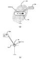
図7は、本実施形態における街灯(発光部)の配置状態を示す図であり、特定の範囲に発光部121m〜121tが設けられた街灯120m〜120tが敷設される。尚、これらの街灯120m〜120tは上記第1の実施の形態と同様、施設122を備え、この施設により照明制御、変調制御、及び、情報送信のための発光タイミングの同期制御が集中管理されている。
FIG. 7 is a diagram illustrating an arrangement state of street lamps (light emitting units) in the present embodiment, and
図8(a)は、発光部121m〜121tが送信する情報のデータフォーマット910である。このデータフォーマットは上記第1の実施の形態にて詳述した、光源ユニークID情報911、案内ポイントID情報912、表示情報903に相当する「表示情報1」916、「表示情報2」917に加え、境界線フラグ913、境界ポイントナンバー情報914、及び、トータル境界数情報915が設定されている。
FIG. 8A shows a
図8(b)は、発光部121m〜121tが夫々時間的に輝度変化しながら発光することにより送信する情報の内容を示すものである。同図において、例えば、発光部121mは、光源ユニークID情報911として「01」、案内ポイントID情報912として「123」、境界線フラグ913として「1」、境界ポイントナンバー情報914として「1」、トータル境界数情報915として「6」、「表示情報1」916としてこの特定の範囲に存在する施設情報「××公園」、「表示情報2」917としてこの発光部121mを有する街灯120m付近の地点情報「○○交差点付近」が設定されている。
FIG. 8B shows the contents of information transmitted by the
また、この図8(a)、及び、(b)において、境界線フラグ913は、その発光部(街灯)が設置された地点が、当該特定の範囲の外周に存在するか否かに基づいて「1」或いは「0」が設定されるものである。例えば、図7において、発光部121m、121n、121o、121t、121s、及び、121pを有する街灯120m、120n、120o、120t、120s、及び、120pはこの特定の範囲の外周部に敷設されたものであるため、境界線フラグ913に「1」が設定されるが、発光部121q、及び、121rを有する街灯120q、及び、120rはこの特定の範囲の内部に敷設されたものであるため、境界線フラグ913に「0」が設定される。
8A and 8B, the
境界線ポイントナンバー情報914は、上記境界線フラグ913に「1」が設定された発光部において所定の規則に従い順番付けた番号(数)が設定される。例えば、本実施の形態では右回りに順次番号が付される。例えば、図7において、発光部121m、121n、121o、121t、121s、及び、121pを有する街灯120m、120n、120o、120t、120s、及び、120pは右回りに1〜6の番号が設定される。尚、境界線フラグ913に「0」が設定された発光部においては、「0」若しくは“null”コードが付される。トータル境界数情報915は、この特定の範囲に敷設され、上記境界線フラグ913に「1」が設定された発光部の総数を示すものである。
The boundary
次に、本実施の形態のデジタルカメラ800の制御部806の処理内容を図9、及び、図10のフローチャートを用いて説明する。
まず、ステップ5にて同一の案内ポイントID情報を有する輝点座標が複数存在すると判断した場合(ステップS5→Yes)、これら複数の輝点座標の復号された情報に共通して含まれる、トータル境界数情報915に設定された数だけの輝点座標が存在するか否かを判断する(ステップS61)。トータル境界数情報915に設定された数だけ輝点座標が存在すると判断すると(ステップS61→Yes)、境界ポイントナンバー情報914に設定された番号の順に各基点座標を接続して外接多角形を設定し(ステップS62)、図5のステップS7に移行する。
Next, processing contents of the
First, when it is determined in
一方、トータル境界数情報915に設定された数だけ輝点座標が存在しない判断すると(ステップS61→No)、複数の輝点座標から復号した夫々の情報の境界ポイントナンバー情報914を参照し、境界ポイントナンバー“1”と、トータル境界数情報915に設定された数と同じ値の境界ポイントナンバーと、を有する情報に対応する輝点座標が存在するか否かを判断する(ステップS63)。
そして、境界ポイントナンバー“1”と、トータル境界数情報915に設定された数と同じ値の境界ポイントナンバーと、を有する情報に対応する輝点座標が存在すると判断すると(ステップS63→Yes)、それらの輝点座標を接続した確定境界線を設定し(ステップS64)、さらに、複数の輝点座標から復号した夫々の情報における境界ポイントナンバー情報914を再度参照し、境界ポイントナンバーが続く情報に対応する輝点座標が存在するか否かを判断する(ステップS65)。
On the other hand, if it is determined that there are no bright spot coordinates as many as the number set in the total boundary number information 915 (step S61 → No), the boundary
When it is determined that there is a bright point coordinate corresponding to information having the boundary point number “1” and the boundary point number having the same value as the number set in the total boundary number information 915 (step S63 → Yes), A definite boundary line connecting these bright spot coordinates is set (step S64), and the boundary
そして、境界ポイントナンバーが続く情報に対応する輝点座標が存在すると判断すると(ステップS65→Yes)、それらの輝点座標を接続した確定境界線を設定し(ステップS66)、ステップS64にて設定した確定境界線とステップS66で設定した確定境界線との間について特定のパターンのハッチング領域を設定する(ステップS67)。そして、この設定された確定境界線とこれらの確定境界線の端部に位置する輝点座標に「表示情報2」917を、ハッチング領域とこのハッチング領域の中心に「表示情報1」916を夫々スルー画像上に重畳表示するよう制御し(ステップS68)、ステップS11に移行する。
If it is determined that there is a bright spot coordinate corresponding to the information with the boundary point number (step S65 → Yes), a definite boundary line connecting these bright spot coordinates is set (step S66), and set in step S64. A hatching area having a specific pattern is set between the determined boundary line and the determined boundary line set in step S66 (step S67). Then, “
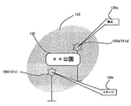
図11はステップS68における表示部808の表示態様を示す図である。
同図は、図7に示した「街灯(発光部)の配置状態」を表示部808に表示させた状態、すなわち、撮像画角内に発光部121m、121o、121p、及び、121tによる輝点のみが含まれる場合を示したものであり、図8(b)において、境界ポイントナンバー“1”を送信する発光部121mによる輝点座標とトータル境界数情報915に設定された数、すなわち“6”と同じ値の境界ポイントナンバーを送信する発光部121pによる輝点座標とを接続する確定境界線128が設定されている。
一方、境界ポイントナンバーが続く情報を送信する発光部は、図8(b)において、境界ポイントナンバー“3”を送信する発光部121o、及び、境界ポイントナンバー“4”を送信する発光部121tになるので、これらの輝点座標を接続する確定境界線128が設定されている。
FIG. 11 is a diagram showing a display mode of the
The figure shows a state where the “street lamp (light emitting unit) arrangement state” shown in FIG. 7 is displayed on the
On the other hand, in FIG. 8B, the light emitting unit that transmits the information having the boundary point number is transmitted to the light emitting unit 121o that transmits the boundary point number “3” and the
また、これらの確定境界線128の間は特定のパターンのハッチング領域129が設定されており、このハッチング領域の中心に、「表示情報1」916である表示内容127、すなわち「××公園」が、また、発光部121m、121o、121p、及び、121tによる輝点座標には、「表示情報2」917である「○○交差点付近」の吹き出し表示130m、「××交差点付近」の吹き出し表示130o、「中央入口」の吹き出し表示130p、及び、「南口」の吹き出し表示130tが、夫々重畳表示されている。
In addition, a
したがって、範囲内に存在する全ての発光部から情報を受け取ることができない場合であっても、操作者は、その範囲のおおよその広さ、及び、名称等の表示情報や、各発光部付近の表示情報を把握することができる。 Therefore, even if information cannot be received from all the light emitting units existing in the range, the operator can display information such as the approximate size of the range and the name, and the vicinity of each light emitting unit. Display information can be grasped.
一方、ステップS65において、境界ポイントナンバーが続く情報に対応する輝点座標が存在しないと判断すると(ステップS65→No)、さらに、複数の輝点座標から復号した夫々の情報における境界線フラグ913を参照し、境界線フラグ913に「0」が設定されている情報に対応する輝点座標が存在するか否かを判断する(ステップS71)。
そして、境界線フラグ913に「0」が設定されている情報に対応する輝点座標が存在すると判断すると(ステップS71→Yes)、この境界線フラグに「0」が設定されている情報に対応する輝点座標が存在する方向に向けて特定の形状、具体的には矢印を模した特定のパターンのハッチング領域を設定する(ステップS72)。そして、この設定された確定境界線の端部に位置する輝点座標に「表示情報2」917を、ハッチング領域とこのハッチング領域の中心に「表示情報1」916を夫々スルー画像上に重畳表示するよう制御し(ステップS68)、ステップS11に移行する。
On the other hand, if it is determined in step S65 that there is no bright spot coordinate corresponding to the information with the boundary point number (step S65 → No), the
When it is determined that there is a bright spot coordinate corresponding to information for which “0” is set in the boundary line flag 913 (step S71 → Yes), it corresponds to information in which “0” is set in the boundary line flag. A hatching area having a specific shape, specifically a specific pattern imitating an arrow, is set in the direction in which the bright spot coordinates exist (step S72). Then, “
図12はステップS72を経由してステップS68の処理を行った場合における表示部808の表示態様を示す図である。
同図は、図7に示した「街灯(発光部)の配置状態」を表示部808に表示させた状態、すなわち、撮像画角内に発光部121m、121p、及び、121qによる輝点のみが含まれる場合を示したものであり、図8(b)において、境界ポイントナンバー“1”を送信する発光部121mによる輝点座標とトータル境界数情報915に設定された数、すなわち“6”と同じ値の境界ポイントナンバーを送信する発光部121pによる輝点座標とを接続する確定境界線128が設定されている。
FIG. 12 is a diagram showing a display mode of the
This figure shows a state in which the “arrangement state of street lamps (light emitting units)” shown in FIG. In FIG. 8B, the bright spot coordinates by the
一方、境界フラグ913に「0」が設定されている情報を送信する発光部は、図8(b)において、発光部121qになるので、この発光部121qによる輝点座標が存在する方向に向けて矢印を模した特定のパターンのハッチング領域131が設定されている。
また、このハッチング領域131の中心には、「表示情報1」916である表示内容127、すなわち「××公園」が、また、発光部121m、121p、121qによる輝点座標には、「表示情報2」917である「○○交差点付近」の吹き出し表示130m、「中央入口」の吹き出し表示130p、及び、「噴水」の吹き出し表示130qが夫々重畳表示されている。
On the other hand, the light-emitting unit that transmits information in which “0” is set in the
Further, in the center of the
したがって、範囲内に存在する全ての発光部から情報を受け取ることができない場合であっても、その範囲の内部領域に存在する発光部からの情報を受け取ることができれば、操作者は、その範囲の広がりの方向、及び、名称等の表示情報や、各発光部付近の表示情報を把握することができる。 Therefore, even if the information cannot be received from all the light emitting units existing in the range, if the information from the light emitting unit existing in the inner area of the range can be received, the operator It is possible to grasp display information such as the direction of spread and name, and display information near each light emitting unit.
また、ステップS71において、境界線フラグ913に「0」が設定されている情報に対応する輝点座標が存在しない、すなわち、境界フラグ913に「1」が設定されている輝点座標が存在すると判断すると(ステップS71→No)、予め設定された解析方法に従って特定のパターンのハッチング領域を設定し(ステップS73)、この設定された確定境界線の端部に位置する輝点座標に「表示情報2」917を、ハッチング領域とこのハッチング領域の中心に「表示情報1」916を夫々スルー画像上に重畳表示するよう制御し(ステップS68)、ステップS11に移行する。
In step S71, if there is no bright spot coordinate corresponding to information for which “0” is set in the
上記ステップS73にて処理される「予め設定された解析方法」とは、具体的には以下の通りである。
・トータル境界数情報と同じ値の境界ポイントナンバー情報を送信する輝点座標と、境界ポイントナンバー情報“1”を送信する輝点座標とを結ぶ確定境界線が設定される場合、トータル境界数情報と同じ値の境界ポイントナンバー情報を送信する輝点座標から境界ポイントナンバー情報“1”を送信する輝点座標へ向かう方向の右側をハッチング領域を設定すべき範囲とする。
・輝点座標が少なくとも2つ存在し、これらの輝点座標に対応する情報において境界ポイントナンバー情報の番号が順次続く場合、この番号の小さい方の輝点座標から大きい方の輝点座標へ向かう方向の右側をハッチング領域を設定すべき範囲とする。
The “preliminary analysis method” processed in step S73 is specifically as follows.
When the definite boundary line connecting the bright spot coordinates that transmit the boundary point number information having the same value as the total boundary number information and the bright spot coordinates that transmit the boundary point number information “1” is set, the total boundary number information The hatching area is to be set on the right side in the direction from the bright spot coordinates for transmitting the boundary point number information having the same value to the bright spot coordinates for transmitting the boundary point number information “1”.
When there are at least two bright spot coordinates and the boundary point number information number sequentially follows information corresponding to these bright spot coordinates, the smaller bright spot coordinates go to the larger bright spot coordinates. The right side of the direction is the range where the hatching area should be set.
したがって、範囲内に存在する全ての発光部から情報を受け取ることができない場合であっても、その範囲の外周部の一部の発光部からの情報を受け取ることができれば、操作者は、その範囲の広がりの方向、及び、名称等の表示情報や、各発光部付近の表示情報を把握することができる。 Therefore, even if information cannot be received from all the light emitting units existing in the range, if the information can be received from a part of the light emitting units on the outer periphery of the range, the operator can change the range. Display information such as the direction of spread and name, and display information in the vicinity of each light emitting unit can be grasped.
また、ステップS63において、境界ポイントナンバー“1”と、トータル境界数情報915に設定された数と同じ値の境界ポイントナンバーと、を有する情報に対応する輝点座標が存在しないと判断すると(ステップS63→No)、上記ステップS65と同様に、境界ポイントナンバーが続く情報に対応する輝点座標が存在するか否かを判断する(ステップS69)。
そして、境界ポイントナンバーが続く情報に対応する輝点座標が存在すると判断すると(ステップS69→Yes)、それらの輝点座標を接続した確定境界線を設定し(ステップS70)、更に、さらに、複数の輝点座標から復号した夫々の情報における境界線フラグ913を参照し、境界線フラグ913に「0」が設定されている情報に対応する輝点座標が存在するか否かを判断する(ステップS71)。
If it is determined in step S63 that there is no bright spot coordinate corresponding to the information having the boundary point number “1” and the boundary point number having the same value as the number set in the total boundary number information 915 (step S63). S63 → No), similarly to step S65 described above, it is determined whether there is a bright spot coordinate corresponding to the information with the boundary point number (step S69).
If it is determined that there is a bright spot coordinate corresponding to the information with the boundary point number (step S69 → Yes), a fixed boundary line connecting these bright spot coordinates is set (step S70). Referring to the
そして、境界線フラグ913に「0」が設定されている情報に対応する輝点座標が存在すると判断すると(ステップS71→Yes)、この境界線フラグに「0」が設定されている情報に対応する輝点座標が存在する方向に向けて特定の形状、具体的には矢印を模した特定のパターンのハッチング領域を設定する(ステップS72)。そして、この設定された確定境界線の端部に位置する輝点座標に「表示情報2」917を、ハッチング領域とこのハッチング領域の中心に「表示情報1」916を夫々スルー画像上に重畳表示するよう制御し(ステップS68)、ステップS11に移行する。
When it is determined that there is a bright spot coordinate corresponding to information for which “0” is set in the boundary line flag 913 (step S71 → Yes), it corresponds to information in which “0” is set in the boundary line flag. A hatching area having a specific shape, specifically a specific pattern imitating an arrow, is set in the direction in which the bright spot coordinates exist (step S72). Then, “
したがって、範囲内に存在する全ての発光部から情報を受け取ることができない場合であっても、その範囲の内部領域に存在する発光部からの情報を受け取ることができれば、操作者は、その範囲の広がりの方向、及び、名称等の表示情報や、各発光部付近の表示情報を把握することができる。 Therefore, even if the information cannot be received from all the light emitting units existing in the range, if the information from the light emitting unit existing in the inner area of the range can be received, the operator It is possible to grasp display information such as the direction of spread and name, and display information near each light emitting unit.
一方、ステップS71において、境界線フラグ913に「0」が設定されている情報に対応する輝点座標が存在しないと判断すると(ステップS71→No)、上述の予め設定された解析方法に従って特定のパターンのハッチング領域を設定し(ステップS73)、この設定された確定境界線の端部に位置する輝点座標に「表示情報2」917を、ハッチング領域とこのハッチング領域の中心に「表示情報1」916を夫々スルー画像上に重畳表示するよう制御し(ステップS68)、ステップS11に移行する。
On the other hand, if it is determined in step S71 that there is no bright spot coordinate corresponding to the information for which the
図12はステップS69(Yes)→ステップS70→ステップS71(No)→ステップS73を経由してステップS68の処理を行った場合における表示部808の表示態様を示す図である。
同図は、図7に示した「街灯(発光部)の配置状態」を表示部808に表示させた状態、すなわち、撮像画角内に発光部121n、121o、及び、121tによる輝点のみが含まれる場合を示したものであり、図8(b)において、境界ポイントナンバー“2”を送信する発光部121nによる輝点座標と上記境界ポイントナンバー“2”の次の“3”を送信する発光部121oによる輝点座標とを接続する確定境界線128が設定されている。また、境界ポイントナンバー“3”を送信する発光部121oによる輝点座標と上記境界ポイントナンバー“3”の次の“4”を送信する発光部121tによる輝点座標とを接続する確定境界線128が設定されている。
FIG. 12 is a diagram showing a display mode of the
This figure shows a state in which the “street lamp (light emitting unit) arrangement state” shown in FIG. 7 is displayed on the
そして、確定境界線の境界ポイントナンバーが“2”→“3”→“4”と続く方向の右側がハッチング領域の設定範囲となり、発光部121n、121o、及び、121tを頂点する三角形の内部にハッチング領域132が設定されている。
また、このハッチング領域132の中心には、「表示情報1」916である表示内容127、すなわち「××公園」が、また、発光部121n、121o、121tによる輝点座標には、「表示情報2」917である「北口」の吹き出し表示130n、「××交差点付近」の吹き出し表示130o、及び、「南口」の吹き出し表示130tが夫々重畳表示されている。
Then, the right side of the direction in which the boundary point number of the definite boundary line is “2” → “3” → “4” is the setting range of the hatching area, and inside the triangles that apex the
Further, in the center of the
したがって、範囲内に存在する全ての発光部から情報を受け取ることができない場合であっても、その範囲の外周部の一部の発光部からの情報を受け取ることができれば、操作者は、その範囲の広がりの方向、及び、名称等の表示情報や、各発光部付近の表示情報を把握することができる。 Therefore, even if information cannot be received from all the light emitting units existing in the range, if the information can be received from a part of the light emitting units on the outer periphery of the range, the operator can change the range. Display information such as the direction of spread and name, and display information in the vicinity of each light emitting unit can be grasped.
一方、ステップS69にて境界ポイントナンバーが続く情報に対応する輝点座標が存在しないと判断すると(ステップS69→No)、撮影画角内に輝点座標が一つのみ存在するか否かを判断する(ステップS74)。
そして、一つのみ存在すると判断した場合(ステップS74→Yes)、その輝点座標から送信された情報において境界線フラグ913に「0」が設定されているか否かを判断する(ステップS75)。境界線フラグ913に「0」が設定されていると判断した場合(ステップS75→Yes)、この輝点座標を中心とする特定パターンのハッチング領域を設定し(ステップS76)、このハッチング領域の中心に「表示情報1」916を、この輝点座標に「表示情報2」917を、夫々スルー画像上に重畳表示するよう制御し(ステップS77)、ステップS11に移行する。
On the other hand, if it is determined in step S69 that there is no bright spot coordinate corresponding to the information followed by the boundary point number (step S69 → No), it is determined whether or not there is only one bright spot coordinate within the shooting angle of view. (Step S74).
If it is determined that only one exists (step S74 → Yes), it is determined whether or not “0” is set in the
図14(a)はステップS77の処理を行った場合における表示部808の表示態様を示す図である。
同図は、図7に示した「街灯(発光部)の配置状態」を表示部808に表示させた状態、すなわち、撮像画角内に発光部121rによる輝点のみが含まれる場合を示したものであり、図8(b)において発光部121rは、境界フラグ913に「0」が設定されている情報を送信しているので、この発光部121rによる輝点座標を中心に特定パターンのハッチング領域133が設定されている。
また、このハッチング領域131の中心には、「表示情報1」916である表示内容127、すなわち「××公園」が、また、発光部121rによる輝点座標には、「表示情報2」917である「ステージ」の吹き出し表示130rが夫々重畳表示されている。
FIG. 14A is a diagram illustrating a display mode of the
This figure shows a state where the “street lamp (light emitting unit) arrangement state” shown in FIG. 7 is displayed on the
Further, in the center of the
したがって、範囲内に存在する全ての発光部から情報を受け取ることができない場合であっても、その範囲の内部領域に存在する発光部からのみの情報を受け取ることができれば、操作者は、その範囲が座標点のみの情報ではなく、ある程度の広がりがある範囲であることを把握することができるとともに、その範囲の名称等の表示情報や、発光部付近の表示情報を把握することができる。 Therefore, even if information cannot be received from all the light emitting units existing in the range, if the information can be received only from the light emitting units existing in the inner area of the range, the operator can change the range. Is not only information on coordinate points but a range with a certain extent, and display information such as the name of the range and display information in the vicinity of the light emitting unit can be recognized.
一方、ステップS75において、境界線フラグ913に「0」が設定されていない、すなわち、境界線フラグ913に「1」が設定されていると判断した場合(ステップS75→No)、この輝点座標を中心とした特定の確定境界線を設定し(ステップS78)、この輝点座標に「表示情報1」916、「表示情報2」917を、夫々スルー画像上に重畳表示するよう制御し(ステップS79)、ステップS11に移行する。
On the other hand, if it is determined in step S75 that “0” is not set in the
図14(b)はステップS79の処理を行った場合における表示部808の表示態様を示す図である。
同図は、図7に示した「街灯(発光部)の配置状態」を表示部808に表示させた状態、すなわち、撮像画角内に発光部121nによる輝点のみが含まれる場合を示したものであり、図8(b)において発光部121nは、境界フラグ913に「1」が設定されている情報を送信しているので、この発光部121nによる輝点座標を中心に十字の特定の確定境界線134が設定されている。
また、この輝点座標には、「表示情報1」916である「××公園」と「表示情報2」917である「北口」とが吹き出し表示130nが夫々重畳表示されている。
FIG. 14B is a diagram showing a display mode of the
The figure shows a state in which the “street lamp (light emitting unit) arrangement state” shown in FIG. 7 is displayed on the
In addition, a
したがって、範囲内に存在する全ての発光部から情報を受け取ることができない場合であっても、その範囲の外周に存在する発光部からのみの情報を受け取ることができれば、操作者は、その輝点座標が示す地点が、ある程度の広がりがある範囲の外周であることを把握することができるとともに、その外周で囲まれる範囲の名称等の表示情報や、発光部付近の表示情報を把握することができる。 Therefore, even if the information cannot be received from all the light emitting units existing in the range, if the information can be received only from the light emitting units existing in the outer periphery of the range, the operator can obtain the bright spot. It is possible to grasp that the point indicated by the coordinates is the outer periphery of a range that has a certain extent, and it is possible to grasp the display information such as the name of the range surrounded by the outer periphery, and the display information near the light emitting unit it can.
一方、ステップS74にて撮影画角内に輝点座標が一つのみ存在しない、すなわち、複数存在すると判断した場合(ステップS74→No)、それらの輝点座標から送信された情報において、境界線フラグ913に「0」が設定されているか否かを判断する(ステップS80)。境界線フラグ913に「0」が設定されていると判断した場合(ステップS80→Yes)、これらの輝点座標を含む特定パターンのハッチング領域を設定し(ステップS81)、ステップS77に移行する。 On the other hand, when it is determined in step S74 that only one bright spot coordinate does not exist within the shooting angle of view, that is, there are a plurality of bright spot coordinates (step S74 → No), in the information transmitted from these bright spot coordinates, the boundary line It is determined whether or not “0” is set in the flag 913 (step S80). When it is determined that “0” is set in the boundary flag 913 (step S80 → Yes), a hatching area of a specific pattern including these bright spot coordinates is set (step S81), and the process proceeds to step S77.
図15はステップS81を経由したステップS77の処理を行った場合における表示部808の表示態様を示す図である。
同図は、図7に示した「街灯(発光部)の配置状態」を表示部808に表示させた状態、すなわち、撮像画角内に発光部121qによる輝点と、発光部121rによる輝点が含まれる場合を示したものであり、図8(b)において発光部121q、121rはともに境界フラグ913に「0」が設定されている情報を送信しているので、これら発光部121q、121rによる輝点座標を含む特定パターンのハッチング領域133が設定されている。
また、このハッチング領域131の中心には、「表示情報1」916である表示内容127、すなわち「××公園」が、また、発光部121qによる輝点座標には、「表示情報2」917である「噴水」の吹き出し表示130r、発光部121rによる輝点座標には、「表示情報2」917である「ステージ」の吹き出し表示130rが、夫々重畳表示されている。
FIG. 15 is a diagram showing a display mode of the
This figure shows a state in which the “arrangement state of street lamps (light emitting units)” shown in FIG. 7 is displayed on the
Further, in the center of the
したがって、範囲内に存在する全ての発光部から情報を受け取ることができない場合であっても、その範囲の内部領域に存在する複数の発光部から情報を受け取ることができれば、操作者は、それらの発光部が互いに独立しておらず共通の範囲に含まれていることを把握することができるとともに、その共通の範囲の名称等の表示情報や、発光部付近の表示情報を把握することができる。 Therefore, even if information cannot be received from all the light emitting units existing in the range, if the information can be received from a plurality of light emitting units existing in the inner area of the range, the operator can It is possible to grasp that the light emitting parts are not independent from each other and are included in a common range, and it is possible to grasp display information such as the name of the common range and display information near the light emitting part. .
一方、ステップS78にて境界線フラグ913に「0」が設定されていない、すなわち、「1」が設定されていると判断した場合(ステップS80→No)、これらの輝点座標について、その輝点座標を中心とした特定の確定境界線を設定し(ステップS82)、夫々の輝点座標に「表示情報1」916、「表示情報2」917を、夫々スルー画像上に重畳表示するよう制御し(ステップS83)、ステップS11に移行する。
On the other hand, if it is determined in step S78 that “0” is not set in the
図16はステップS83における表示部808の表示態様を示す図である。
同図は、図7に示した「街灯(発光部)の配置状態」を表示部808に表示させた状態、すなわち、撮像画角内に発光部121mによる輝点と、発光部121tによる輝点のみが含まれる場合を示したものであり、図8(b)において発光部121m、121tはともに境界フラグ913に「1」が設定されている情報を送信しているので、夫々の輝点座標を中心に十字の特定の確定境界線134が設定されている。
また、発光部121mに対応する輝点座標には、「表示情報1」916である「××公園」と「表示情報2」917である「○○交差点付近」とが吹き出し表示1301mに重畳表示されており、発光部121tに対応する輝点座標には、「表示情報1」916である「××公園」と「表示情報2」917である「南口」とが吹き出し表示1301tに重畳表示されている。
FIG. 16 is a diagram showing a display mode of the
The figure shows a state in which the “street lamp (light emitting unit) arrangement state” shown in FIG. 7 is displayed on the
In addition, in the bright spot coordinates corresponding to the
したがって、範囲内に存在する全ての発光部から情報を受け取ることができない場合であっても、その範囲の外周に存在する複数の発光部から情報を受け取ることができれば、操作者は、それらの発光部が互いに独立しておらず共通の範囲に含まれていることを把握することができるとともに、その共通の範囲の名称等の表示情報や、発光部付近の表示情報を把握することができる。
このように第2の実施の形態によれば、範囲内の全ての発光部から情報を受け取ることができない場合であっても、その範囲の広がりや広がりの方向、または、共通の範囲に含まれることや、その範囲の名称等の表示情報や、その発光部付近の表示情報を把握することができる。
Therefore, even when information cannot be received from all the light emitting units existing in the range, if the information can be received from a plurality of light emitting units existing in the outer periphery of the range, the operator can emit the light from those units. It is possible to grasp that the parts are not independent from each other and are included in a common range, and it is possible to grasp display information such as the name of the common range and display information in the vicinity of the light emitting part.
As described above, according to the second embodiment, even when information cannot be received from all the light emitting units within the range, the range is expanded or expanded, or included in a common range. And display information such as the name of the range, and display information in the vicinity of the light emitting unit.
尚、第2の実施の形態においては、送信すべき情報に境界線フラグ913を設定することにより、その発光部がある特定の範囲の外周に存在するか、或いは、その特定の範囲の内部に存在するのかを規定していたが、この境界線フラグ913を設定することなく、境界ポイントナンバー情報914に「0(もしくは“null”コード)」が設定されているか否かで、その発光部がある特定の範囲の外周に存在するか、或いは、その特定の範囲の内部に存在するのかを規定するようにしてもよい。
そしてこのようにすることで、発光部が送信すべき情報を少なくし、情報の復号処理にかかる負担を軽減させることができる。
In the second embodiment, by setting the
By doing so, it is possible to reduce the information to be transmitted by the light emitting unit and reduce the burden on the information decoding process.
また、本実施の形態では、情報を送信する発光部(発光装置)が敷設された都市を俯瞰撮影する場合について述べたが、これに限ることなく、面による表現や三次元CGなど立体的なオブジェクトを表示することによる表現等、ある程度広がりのある情報についての送信・復号表示に有効である。 In the present embodiment, the case where the city where the light emitting unit (light emitting device) for transmitting information is laid down is photographed is described, but the present invention is not limited to this. This is effective for transmission / decoding display of information having a certain degree of spread, such as expression by displaying an object.
120a〜120t 街灯
121a〜121t 発光部
123a〜123l 駆動制御部
124 情報変調部
125 情報記憶部
126 外接多角形
127 表示内容
128、134 確定境界線
129、131〜133 ハッチング領域
130m〜130r、130t 吹き出し表示
800 デジタルカメラ
802 撮像部
803 バッファ
804 復号処理部
805 画像処理部
806 制御部
807 プログラムメモリ
808 表示部
900、910 データフォーマット
901、911 光源ユニークID情報
902、912 案内ポイントID情報
903 表示情報
913 境界線フラグ
914 境界ポイントナンバー情報
915 トータル境界数情報
916 表示情報1
917 表示情報2
1301m、1301t 吹き出し表示
8031 座標データリスト
120a to
917
1301m,
Claims (8)
この受光手段が受光した光の変化から情報を夫々復号する復号手段と、Decoding means for respectively decoding information from changes in light received by the light receiving means;
この復号手段によって夫々復号された情報に含まれる共通情報と、前記複数の発光装置が発光した前記時間的な変化を有する光の前記受光手段における受光位置と、を対応付けて複数組記憶する記憶手段と、A memory for storing a plurality of sets of the common information included in the information decoded by the decoding means and the light receiving positions in the light receiving means of the light having the temporal change emitted by the plurality of light emitting devices in association with each other. Means,
前記記憶手段が、更に境界線情報を複数記憶したか否かを判断する第1の判断手段と、First determining means for determining whether or not the storage means further stores a plurality of boundary line information;
この第1の判断手段により更に境界線情報を記憶したと判断すると、これら境界線情報が記憶された受光位置を線で結ぶように表示する表示手段と、When it is determined that the boundary line information is further stored by the first determination unit, the display unit displays the light receiving positions where the boundary line information is stored so as to be connected by a line;
を備えることを特徴とする情報復号装置。An information decoding apparatus comprising:
前記表示手段は、前記記憶手段によって記憶された受光位置のうち、前記境界線情報が記憶された受光位置について前記順番情報に沿って線で結ぶように表示することを特徴とする請求項1又は2記載の情報復号装置。 The storage means further comprises second determination means for determining whether or not the order information is stored in addition to the boundary line information;
The display means displays the light receiving positions where the boundary line information is stored among the light receiving positions stored by the storage means so as to be connected by a line along the order information. 2. The information decoding device according to 2 .
前記表示手段は、前記境界線情報が記憶された受光位置を線で結び、且つ、その境界線で囲まれた範囲に前記第1の表示情報を表示することを特徴とする請求項1乃至4の何れかに記載の情報復号装置。 The common information includes first display information common to a range surrounded by the boundary line information,
5. The display unit connects the light receiving positions where the boundary line information is stored with a line, and displays the first display information in a range surrounded by the boundary line. An information decoding device according to any one of the above .
前記表示手段は、前記記憶された受光位置のうち、前記第2の表示情報が記憶された受光位置についてその受光位置の近くに前記第2の表示情報を表示することを特徴とする請求項1乃至5の何れかに記載の情報復号装置。 The storage means further comprises third determination means for determining whether or not the second display information individually set for the plurality of light emitting devices is stored in addition to the common information.
The display means displays the second display information in the vicinity of the light receiving position of the stored light receiving position for the light receiving position in which the second display information is stored. The information decoding device according to any one of 1 to 5 .
この受光ステップにて受光された光の変化から情報を夫々復号する復号ステップと、A decoding step for respectively decoding information from changes in the light received in the light receiving step;
この復号ステップにて夫々復号された情報に含まれる共通情報と、前記複数の発光装置が発光した前記時間的な変化を有する光の前記受光部における受光位置と、を対応付けて複数組記憶させる記憶ステップと、A plurality of sets of common information included in the information decoded in the decoding step and a light receiving position in the light receiving unit of the light having the temporal change emitted by the plurality of light emitting devices are stored in association with each other. A memory step;
前記記憶ステップにて更に境界線情報を複数記憶したか否かを判断する判断ステップと、A determination step of determining whether or not a plurality of boundary line information is stored in the storage step;
この判断ステップにて更に境界線情報を記憶したと判断すると、これら境界線情報が記憶された受光位置を線で結ぶように表示させる表示ステップと、If it is determined that the boundary line information is further stored in this determination step, a display step for displaying the light receiving positions where the boundary line information is stored so as to be connected by a line;
を含むことを特徴とする情報復号方法。An information decoding method comprising:
外部に存在し、情報を時間的な光の変化に変調させて発光する複数の発光装置による発光を連続して受光させる受光手段、A light receiving means for continuously receiving light emitted by a plurality of light emitting devices that exist outside and modulate light by temporal change in light;
この受光手段によって受光された光の変化から情報を夫々復号する復号手段、Decoding means for decoding information from changes in light received by the light receiving means,
この復号手段によって夫々復号された情報に含まれる共通情報と、前記複数の発光装置が発光した前記時間的な変化を有する光の前記受光部における受光位置と、を対応付けて複数組記憶させる記憶手段、A storage for storing a plurality of sets of common information included in the information decoded by the decoding unit and a plurality of sets of light receiving positions of the light having a temporal change emitted from the plurality of light emitting devices in association with each other. means,
前記記憶手段によって更に境界線情報を複数記憶したか否かを判断する判断手段、Determination means for determining whether or not a plurality of boundary line information is further stored by the storage means;
この判断手段によって更に境界線情報を記憶したと判断すると、これら境界線情報が記憶された受光位置を線で結ぶように表示させる表示手段、When it is determined that the boundary line information is further stored by the determination unit, the display unit displays the light receiving positions where the boundary line information is stored so as to be connected by lines.
として機能させることを特徴とするプログラム。A program characterized by functioning as
Priority Applications (1)
| Application Number | Priority Date | Filing Date | Title |
|---|---|---|---|
| JP2010142131A JP5099180B2 (en) | 2010-06-23 | 2010-06-23 | Information decoding apparatus, information decoding method, and program |
Applications Claiming Priority (1)
| Application Number | Priority Date | Filing Date | Title |
|---|---|---|---|
| JP2010142131A JP5099180B2 (en) | 2010-06-23 | 2010-06-23 | Information decoding apparatus, information decoding method, and program |
Related Parent Applications (1)
| Application Number | Title | Priority Date | Filing Date |
|---|---|---|---|
| JP2008140704A Division JP4552074B2 (en) | 2008-05-29 | 2008-05-29 | Information transmission system, information decoding apparatus, notification method, and program |
Publications (3)
| Publication Number | Publication Date |
|---|---|
| JP2010268485A JP2010268485A (en) | 2010-11-25 |
| JP2010268485A5 JP2010268485A5 (en) | 2011-07-14 |
| JP5099180B2 true JP5099180B2 (en) | 2012-12-12 |
Family
ID=43365009
Family Applications (1)
| Application Number | Title | Priority Date | Filing Date |
|---|---|---|---|
| JP2010142131A Active JP5099180B2 (en) | 2010-06-23 | 2010-06-23 | Information decoding apparatus, information decoding method, and program |
Country Status (1)
| Country | Link |
|---|---|
| JP (1) | JP5099180B2 (en) |
Families Citing this family (3)
| Publication number | Priority date | Publication date | Assignee | Title |
|---|---|---|---|---|
| JP5928382B2 (en) * | 2013-03-21 | 2016-06-01 | カシオ計算機株式会社 | Imaging device, visible light communication control system, output control method, visible light communication control method, and program |
| JP6285954B2 (en) * | 2013-11-21 | 2018-02-28 | パナソニック インテレクチュアル プロパティ コーポレーション オブ アメリカPanasonic Intellectual Property Corporation of America | Information communication method |
| WO2018142599A1 (en) * | 2017-02-03 | 2018-08-09 | 三菱電機株式会社 | Information acquisition system and device |
Family Cites Families (4)
| Publication number | Priority date | Publication date | Assignee | Title |
|---|---|---|---|---|
| JP3750132B2 (en) * | 2000-03-01 | 2006-03-01 | カシオ計算機株式会社 | Imaging device |
| JP2003179556A (en) * | 2001-09-21 | 2003-06-27 | Casio Comput Co Ltd | Information transmission method, information transmission system, imaging apparatus and information transmission method |
| JP2003348424A (en) * | 2002-05-27 | 2003-12-05 | Sony Corp | Motion tracking apparatus and method thereof |
| JP2007295490A (en) * | 2006-04-27 | 2007-11-08 | Kyocera Corp | Visible optical communication apparatus, and visible light receiving method |
-
2010
- 2010-06-23 JP JP2010142131A patent/JP5099180B2/en active Active
Also Published As
| Publication number | Publication date |
|---|---|
| JP2010268485A (en) | 2010-11-25 |
Similar Documents
| Publication | Publication Date | Title |
|---|---|---|
| JP4552074B2 (en) | Information transmission system, information decoding apparatus, notification method, and program | |
| JP7066822B2 (en) | Image production method at the performance venue using a light emitting device for cheering and an image production system using this | |
| JP4797415B2 (en) | Illumination device, photographing device, and photographing system | |
| EP3002995A1 (en) | Lighting device | |
| CN105121955A (en) | Electric lighting devices having multiple light sources to simulate a flame | |
| KR100707698B1 (en) | Method for arranging light emitting diode module, data converting method for displaying moving picture by using light emitting diode module and data converting apparatus therefor | |
| CN103019014A (en) | Projection apparatus, and projection control method | |
| JP5099180B2 (en) | Information decoding apparatus, information decoding method, and program | |
| JP7241309B2 (en) | PRESENTATION SYSTEM, PRESENTATION DEVICE, AND PRESENTATION METHOD | |
| KR100949516B1 (en) | The system of monitoring or control for led electric sign examination to locate remote area over real time | |
| TWI746973B (en) | Method for guiding a machine capable of autonomous movement through optical communication device | |
| JP5181633B2 (en) | Information transmission system, imaging apparatus, information transmission method, and program | |
| CN104113737B (en) | System for preventing monitoring video from being replaced and method thereof | |
| CN117521179B (en) | Atmosphere lamp equipment, luminous partition layout construction method and device and computer equipment | |
| KR100930950B1 (en) | Lighting control system of miniature | |
| JP4952977B2 (en) | Information transmission system, imaging device, and route guidance program | |
| JP5879839B2 (en) | Image projection system | |
| WO2021031879A1 (en) | Optical communication device and information transmitting and receiving method | |
| JP2000131018A (en) | Three-dimensional spatial position detector, and light emitter and virtual space indicator using the same | |
| JP2006259668A (en) | Emission element bundle lighting point bundle control system | |
| JP2006166406A (en) | Image display system, control method therefor, image processing apparatus, lighting apparatus and control method therefor | |
| KR102084482B1 (en) | System for controlling multi lighting and method lighting control using the same | |
| US20230395013A1 (en) | Image processing apparatus, image processing method, and storage medium | |
| JP2000132325A (en) | Light emitting device for three-dimensional space position detection and virtual space display device using the same | |
| JP2007072548A (en) | Object indication specification system, information terminal, operation object equipment and object indication specification method |
Legal Events
| Date | Code | Title | Description |
|---|---|---|---|
| A521 | Request for written amendment filed |
Free format text: JAPANESE INTERMEDIATE CODE: A523 Effective date: 20110527 |
|
| A621 | Written request for application examination |
Free format text: JAPANESE INTERMEDIATE CODE: A621 Effective date: 20110527 |
|
| TRDD | Decision of grant or rejection written | ||
| A01 | Written decision to grant a patent or to grant a registration (utility model) |
Free format text: JAPANESE INTERMEDIATE CODE: A01 Effective date: 20120828 |
|
| A01 | Written decision to grant a patent or to grant a registration (utility model) |
Free format text: JAPANESE INTERMEDIATE CODE: A01 |
|
| A61 | First payment of annual fees (during grant procedure) |
Free format text: JAPANESE INTERMEDIATE CODE: A61 Effective date: 20120910 |
|
| FPAY | Renewal fee payment (event date is renewal date of database) |
Free format text: PAYMENT UNTIL: 20151005 Year of fee payment: 3 |
|
| R150 | Certificate of patent or registration of utility model |
Ref document number: 5099180 Country of ref document: JP Free format text: JAPANESE INTERMEDIATE CODE: R150 Free format text: JAPANESE INTERMEDIATE CODE: R150 |