JP5097705B2 - Chemical injection device - Google Patents
Chemical injection device Download PDFInfo
- Publication number
- JP5097705B2 JP5097705B2 JP2008522644A JP2008522644A JP5097705B2 JP 5097705 B2 JP5097705 B2 JP 5097705B2 JP 2008522644 A JP2008522644 A JP 2008522644A JP 2008522644 A JP2008522644 A JP 2008522644A JP 5097705 B2 JP5097705 B2 JP 5097705B2
- Authority
- JP
- Japan
- Prior art keywords
- piston
- flange
- chemical
- contact
- actuator
- Prior art date
- Legal status (The legal status is an assumption and is not a legal conclusion. Google has not performed a legal analysis and makes no representation as to the accuracy of the status listed.)
- Active
Links
Images


Classifications
-
- A—HUMAN NECESSITIES
- A61—MEDICAL OR VETERINARY SCIENCE; HYGIENE
- A61M—DEVICES FOR INTRODUCING MEDIA INTO, OR ONTO, THE BODY; DEVICES FOR TRANSDUCING BODY MEDIA OR FOR TAKING MEDIA FROM THE BODY; DEVICES FOR PRODUCING OR ENDING SLEEP OR STUPOR
- A61M5/00—Devices for bringing media into the body in a subcutaneous, intra-vascular or intramuscular way; Accessories therefor, e.g. filling or cleaning devices, arm-rests
- A61M5/14—Infusion devices, e.g. infusing by gravity; Blood infusion; Accessories therefor
- A61M5/142—Pressure infusion, e.g. using pumps
- A61M5/145—Pressure infusion, e.g. using pumps using pressurised reservoirs, e.g. pressurised by means of pistons
- A61M5/1452—Pressure infusion, e.g. using pumps using pressurised reservoirs, e.g. pressurised by means of pistons pressurised by means of pistons
- A61M5/14546—Front-loading type injectors
-
- A—HUMAN NECESSITIES
- A61—MEDICAL OR VETERINARY SCIENCE; HYGIENE
- A61M—DEVICES FOR INTRODUCING MEDIA INTO, OR ONTO, THE BODY; DEVICES FOR TRANSDUCING BODY MEDIA OR FOR TAKING MEDIA FROM THE BODY; DEVICES FOR PRODUCING OR ENDING SLEEP OR STUPOR
- A61M5/00—Devices for bringing media into the body in a subcutaneous, intra-vascular or intramuscular way; Accessories therefor, e.g. filling or cleaning devices, arm-rests
- A61M5/14—Infusion devices, e.g. infusing by gravity; Blood infusion; Accessories therefor
- A61M5/142—Pressure infusion, e.g. using pumps
- A61M5/145—Pressure infusion, e.g. using pumps using pressurised reservoirs, e.g. pressurised by means of pistons
- A61M5/1452—Pressure infusion, e.g. using pumps using pressurised reservoirs, e.g. pressurised by means of pistons pressurised by means of pistons
- A61M5/1458—Means for capture of the plunger flange
-
- A—HUMAN NECESSITIES
- A61—MEDICAL OR VETERINARY SCIENCE; HYGIENE
- A61M—DEVICES FOR INTRODUCING MEDIA INTO, OR ONTO, THE BODY; DEVICES FOR TRANSDUCING BODY MEDIA OR FOR TAKING MEDIA FROM THE BODY; DEVICES FOR PRODUCING OR ENDING SLEEP OR STUPOR
- A61M2205/00—General characteristics of the apparatus
- A61M2205/14—Detection of the presence or absence of a tube, a connector or a container in an apparatus
-
- A—HUMAN NECESSITIES
- A61—MEDICAL OR VETERINARY SCIENCE; HYGIENE
- A61M—DEVICES FOR INTRODUCING MEDIA INTO, OR ONTO, THE BODY; DEVICES FOR TRANSDUCING BODY MEDIA OR FOR TAKING MEDIA FROM THE BODY; DEVICES FOR PRODUCING OR ENDING SLEEP OR STUPOR
- A61M2205/00—General characteristics of the apparatus
- A61M2205/33—Controlling, regulating or measuring
- A61M2205/332—Force measuring means
-
- A—HUMAN NECESSITIES
- A61—MEDICAL OR VETERINARY SCIENCE; HYGIENE
- A61M—DEVICES FOR INTRODUCING MEDIA INTO, OR ONTO, THE BODY; DEVICES FOR TRANSDUCING BODY MEDIA OR FOR TAKING MEDIA FROM THE BODY; DEVICES FOR PRODUCING OR ENDING SLEEP OR STUPOR
- A61M5/00—Devices for bringing media into the body in a subcutaneous, intra-vascular or intramuscular way; Accessories therefor, e.g. filling or cleaning devices, arm-rests
- A61M5/007—Devices for bringing media into the body in a subcutaneous, intra-vascular or intramuscular way; Accessories therefor, e.g. filling or cleaning devices, arm-rests for contrast media
-
- A—HUMAN NECESSITIES
- A61—MEDICAL OR VETERINARY SCIENCE; HYGIENE
- A61M—DEVICES FOR INTRODUCING MEDIA INTO, OR ONTO, THE BODY; DEVICES FOR TRANSDUCING BODY MEDIA OR FOR TAKING MEDIA FROM THE BODY; DEVICES FOR PRODUCING OR ENDING SLEEP OR STUPOR
- A61M5/00—Devices for bringing media into the body in a subcutaneous, intra-vascular or intramuscular way; Accessories therefor, e.g. filling or cleaning devices, arm-rests
- A61M5/14—Infusion devices, e.g. infusing by gravity; Blood infusion; Accessories therefor
- A61M5/142—Pressure infusion, e.g. using pumps
- A61M5/145—Pressure infusion, e.g. using pumps using pressurised reservoirs, e.g. pressurised by means of pistons
- A61M5/1452—Pressure infusion, e.g. using pumps using pressurised reservoirs, e.g. pressurised by means of pistons pressurised by means of pistons
- A61M5/1456—Pressure infusion, e.g. using pumps using pressurised reservoirs, e.g. pressurised by means of pistons pressurised by means of pistons with a replaceable reservoir comprising a piston rod to be moved into the reservoir, e.g. the piston rod is part of the removable reservoir
-
- A—HUMAN NECESSITIES
- A61—MEDICAL OR VETERINARY SCIENCE; HYGIENE
- A61M—DEVICES FOR INTRODUCING MEDIA INTO, OR ONTO, THE BODY; DEVICES FOR TRANSDUCING BODY MEDIA OR FOR TAKING MEDIA FROM THE BODY; DEVICES FOR PRODUCING OR ENDING SLEEP OR STUPOR
- A61M5/00—Devices for bringing media into the body in a subcutaneous, intra-vascular or intramuscular way; Accessories therefor, e.g. filling or cleaning devices, arm-rests
- A61M5/14—Infusion devices, e.g. infusing by gravity; Blood infusion; Accessories therefor
- A61M5/168—Means for controlling media flow to the body or for metering media to the body, e.g. drip meters, counters ; Monitoring media flow to the body
- A61M5/16831—Monitoring, detecting, signalling or eliminating infusion flow anomalies
- A61M5/16854—Monitoring, detecting, signalling or eliminating infusion flow anomalies by monitoring line pressure
Description
本発明は、薬液が充填された薬液シリンジから被験者へ薬液を注入する薬液注入装置に関する。 The present invention relates to a chemical liquid injector that injects a chemical liquid from a chemical syringe filled with the chemical liquid to a subject.
医療用の画像診断装置としては、CT(Computed Tomography)スキャナ、MRI(Magnetic Resonance Imaging)装置、PET(Positron
Emission Tomography)装置、アンギオ装置、およびMRA(MR Angio)装置などがある。これらの装置を使用する際は、被験者に造影剤や生理食塩水などの薬液を注入する必要がある。そこで、薬液の注入を自動で行う種々の薬液注入システムが提案され、実用化されている。Medical diagnostic imaging apparatuses include CT (Computed Tomography) scanner, MRI (Magnetic Resonance Imaging) apparatus, PET (Positron).
Emission Tomography) apparatus, Angio apparatus, MRA (MR Angio) apparatus, and the like. When these devices are used, it is necessary to inject a medical solution such as a contrast medium or physiological saline into the subject. Accordingly, various chemical solution injection systems for automatically injecting chemical solutions have been proposed and put into practical use.
従来の薬液注入システムの一例について説明する。薬液注入システムは、薬液シリンジが着脱自在に装着される注入ヘッドを備えた薬液注入装置と、MRI装置といった画像診断装置と、を有する。 An example of a conventional chemical solution injection system will be described. The chemical solution injection system includes a chemical solution injection device including an injection head to which a chemical solution syringe is detachably attached, and an image diagnostic apparatus such as an MRI apparatus.
薬液シリンジは、一端が開放されているとともに他端に導管部が形成されたシリンダ部材と、シリンダ部材の開放された一端からシリンダ部材内にスライド自在に挿入されているピストン部材と、を有する。シリンダ部材およびピストン部材の一端部にはそれぞれフランジが形成されている。 The chemical syringe includes a cylinder member having one end opened and a conduit portion formed at the other end, and a piston member slidably inserted into the cylinder member from the opened one end of the cylinder member. A flange is formed at one end of each of the cylinder member and the piston member.
注入ヘッドは、薬液シリンジのシリンダ部材が着脱自在に装着されるシリンジ装着部と、保持された薬液シリンジを動作させるシリンジ駆動機構と、を有する。シリンジ駆動機構は、モータ駆動によって前進および後退するロッドを有し、その先端部には、ピストン部材のフランジを保持してピストン部材を押圧するピストン押圧部が設けられている。 The injection head has a syringe mounting portion on which a cylinder member of the chemical syringe is detachably mounted, and a syringe drive mechanism that operates the held chemical syringe. The syringe drive mechanism has a rod that moves forward and backward by motor drive, and a piston pressing portion that holds the flange of the piston member and presses the piston member is provided at the tip thereof.
薬液シリンジは、シリンジ装着部にシリンダ部材が装着されることによって、注入ヘッドに保持される。一方、ピストン部材のフランジはピストン押圧部に保持される。シリンダ部材の導管部には、延長チューブを介して注入針が連結される。注入針を被験者の血管に刺入した状態でロッドを前進させ、ピストン部材をシリンダ部材内に押し込むことにより、シリンダ部材内に充填された薬液が被験者の血管に注入される。 The chemical liquid syringe is held by the injection head by mounting the cylinder member on the syringe mounting portion. On the other hand, the flange of the piston member is held by the piston pressing portion. An injection needle is connected to the conduit portion of the cylinder member via an extension tube. The rod is advanced with the injection needle inserted into the blood vessel of the subject, and the piston member is pushed into the cylinder member, so that the drug solution filled in the cylinder member is injected into the blood vessel of the subject.
被験者へ薬液を注入する際、過剰な圧力が薬液シリンジに加わることによる薬液シリンジの破損を防止するために、所望の圧力で薬液を注入することが重要である。そのため、従来の薬液注入装置はロードセルを内蔵しており、このロードセルによって、ピストン部材に作用する圧力を検出している(特許文献1、2参照)。
特許文献1:特開2003−290343号公報
特許文献2:特開2005−74065号公報When injecting a chemical solution to a subject, it is important to inject the chemical solution at a desired pressure in order to prevent the chemical solution syringe from being damaged due to excessive pressure applied to the chemical solution syringe. Therefore, the conventional chemical injection device has a built-in load cell, and the pressure acting on the piston member is detected by this load cell (see Patent Documents 1 and 2).
Patent Document 1: Japanese Patent Laid-Open No. 2003-290343 Patent Document 2: Japanese Patent Laid-Open No. 2005-74065
しかしながら、ロードセルは抵抗値の変化に基づいてリアルタイムに圧力を検出することができるものであり、その検出回路も複雑なものとなる。また、実際の薬液注入動作においては、過剰な圧力が作用することによる薬液シリンジの破損を防止できればよく、リアルタイムでの詳細な圧力データまでは必要としない場合も多い。また、薬液シリンジが正常に装着されていない状態でシリンジ駆動機構を動作させた場合も、薬液シリンジを破損させる原因となる。 However, the load cell can detect the pressure in real time based on the change of the resistance value, and its detection circuit becomes complicated. Further, in an actual chemical solution injection operation, it is only necessary to prevent the chemical syringe from being damaged due to an excessive pressure acting, and in many cases, detailed pressure data in real time is not required. In addition, when the syringe drive mechanism is operated in a state where the chemical syringe is not normally attached, it may cause damage to the chemical syringe.
本発明は、薬液注入時における薬液シリンジの破損をより簡易な構成で防止できる薬液注入装置を提供することを目的とする。 An object of this invention is to provide the chemical | medical solution injection device which can prevent the failure | damage of the chemical | medical solution syringe at the time of chemical | medical solution injection | pouring with a simpler structure.
上記目的を達成するため本発明の薬液注入装置は、薬液が充填されているシリンダ部材と、シリンダ部材にスライド自在に挿入されているピストン部材と、を有する薬液シリンジを操作して薬液を注入対象へ注入する薬液注入装置であって、シリンダ部材を着脱自在に保持することによって薬液シリンジが装着されるシリンジ装着部と、シリンジ装着部に装着された薬液シリンジのピストン部材を押圧することによって、ピストン部材をシリンダ部材内に押し込むピストン押圧部と、を備えている。ピストン押圧部は、ピストン部材の端部に設けられているフランジを保持するフランジ保持部と、フランジ保持部に保持されたフランジと接触するように突出しており、フランジが保持されることによって変位し、かつ、ピストン押圧部がピストン部材を押し込むことによって、フランジから受ける力でさらに変位することができるように設けられたピストン接触部材と、ピストン接触部材の変位に応じて、フランジを保持する前と保持した後、およびフランジから受ける力が予め決められた力に達する前と達した後で、それぞれ開閉状態が切り替わるスイッチ機構と、一端に設けられた開口部からピストン接触部材を突出させてピストン接触部材を変位可能に収容する中空構造の筐体と、を有している。そして、スイッチ機構は、ピストン接触部材の変位に応じて作動されるアクチュエータおよびアクチュエータを付勢するばねを備えた、筐体の内部に固定された1つまたは2つのスイッチを有する。 In order to achieve the above object, a chemical injection device according to the present invention operates a chemical syringe having a cylinder member filled with a chemical solution and a piston member slidably inserted into the cylinder member to inject the chemical solution. A chemical liquid injection device for injecting into a syringe, a syringe mounting portion to which a chemical liquid syringe is mounted by detachably holding a cylinder member, and a piston member by pressing a piston member of the chemical liquid syringe mounted on the syringe mounting portion. A piston pressing portion for pressing the member into the cylinder member. The piston pressing part protrudes so as to contact the flange holding part that holds the flange provided at the end of the piston member and the flange held by the flange holding part, and is displaced by holding the flange. And a piston contact member provided so as to be able to be further displaced by the force received from the flange when the piston pressing portion pushes the piston member, and before holding the flange according to the displacement of the piston contact member; After holding, before and after the force received from the flange reaches a predetermined force, the switch contact mechanism that switches between open and closed states, and the piston contact member protrudes from the opening provided at one end to contact the piston And a hollow housing that accommodates the member in a displaceable manner. The switch mechanism includes one or two switches fixed inside the housing, each of which includes an actuator that is operated in accordance with the displacement of the piston contact member and a spring that biases the actuator.
上記のとおり構成された本発明の薬液注入装置では、フランジ保持部に保持されたフランジと接触するように、変位可能なピストン接触部材がフランジ押圧部に設けられており、スイッチ機構は、このピストン接触部材の変位に応じて上記のように開閉状態が切り替わる。このことにより、スイッチ機構の開閉状態から、ピストン部材のフランジがピストン押圧部のフランジ保持部に保持されたこと、およびピストン押圧部がピストン部材を押圧している間に、ピストン接触部材がフランジから受ける力が予め決められた力に達したことが検出される。ここで、スイッチ機構によって検出される、ピストン接触部材がフランジから受ける予め決められた力を、薬液シリンジによる薬液の注入圧力が薬液シリンジを破損させるおそれのある注入圧力に対応する力に設定すれば、注入圧力が薬液シリンジを破損させるおそれのある注入圧力に達したか否かが検出される。 In the chemical injection device of the present invention configured as described above, a displaceable piston contact member is provided in the flange pressing portion so as to come into contact with the flange held in the flange holding portion, and the switch mechanism is provided with the piston. The open / close state is switched as described above in accordance with the displacement of the contact member. As a result, from the open / closed state of the switch mechanism, the piston contact member is removed from the flange while the flange of the piston member is held by the flange holding portion of the piston pressing portion, and while the piston pressing portion is pressing the piston member. It is detected that the force received has reached a predetermined force. Here, if the predetermined force received by the piston contact member from the flange, which is detected by the switch mechanism, is set to a force corresponding to the injection pressure at which the injection pressure of the drug solution by the drug syringe may damage the drug syringe. It is detected whether or not the injection pressure has reached an injection pressure that may damage the chemical syringe.
本発明の薬液注入装置において、ピストン押圧部は、筐体の内部に、ピストン接触部材が接触した状態でピストン接触部材がフランジから力を受けて変位することによって、ピストン接触部材と一緒に変位可能に設けられた可動部材と、可動部材をピストン接触部材に向けて付勢する付勢部材と、フランジ保持部にフランジが保持されていないときに、可動部材が付勢部材の付勢力でピストン接触部材と接触しないように、可動部材の位置を規制するストッパと、をさらに有する構成とすることができる。これによれば、ピストン接触部材を上記のように変位するように設けることができる。
In the chemical injection device of the present invention, the piston pressing portion can be displaced together with the piston contact member by the piston contact member being displaced by receiving a force from the flange while the piston contact member is in contact with the inside of the housing. A movable member provided on the movable member, a biasing member that biases the movable member toward the piston contact member, and when the flange is not held by the flange holding portion, the movable member is in piston contact with the biasing force of the biasing member. It can be set as the structure which further has a stopper which controls the position of a movable member so that a member may not be contacted. According to this, a piston contact member can be provided so that it may displace as mentioned above.
スイッチ機構は、ピストン接触部材の変位によって作動されるアクチュエータを備えた双投形の1つのスイッチを有していてもよいし、それぞれピストン接触部材の変位によって作動するアクチュエータを備えた単投形の2つのスイッチを有していてもよい。 The switch mechanism may have a single-throw switch having an actuator that is actuated by displacement of the piston contact member, or a single-throw type that has an actuator that is actuated by displacement of the piston contact member. You may have two switches.
本発明によれば、ロードセルを用いることなく、薬液注入時に薬液シリンジに作用する力が予め決められた力に達したか否かを検出することができる。さらに、薬液シリンジが正常に装着されたか否かも検出することができる。したがって、薬液注入時における薬液シリンジの破損を、簡単な構成でかつ効果的に防止することができる。 According to the present invention, it is possible to detect whether or not the force acting on the drug solution syringe at the time of drug solution injection reaches a predetermined force without using a load cell. Furthermore, it can also be detected whether the chemical | medical solution syringe was mounted | worn normally. Therefore, it is possible to effectively prevent the chemical syringe from being damaged during the injection of the chemical solution with a simple configuration.
100 薬液注入装置
110 注入ヘッド
118 ピストン押圧部
121 押圧部本体
124 ピストン接触部材
125 可動板
126 コイルばね
130、140、150 検出スイッチ
200C、200P 薬液シリンジ
210 シリンダ部材
220 ピストン部材
300 MRI装置
1000 薬液注入システムDESCRIPTION OF
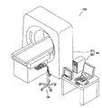
図1を参照すると、薬液注入システム1000は、薬液注入装置100と、撮像装置であるMRI装置300と、を有している。MRI装置300は、被験者から透視画像を撮像する撮像実行機構である撮像ユニット301と、撮像ユニット301の動作を制御する撮像制御ユニット302と、を有している。
Referring to FIG. 1, a chemical
薬液注入装置100は、図2に示すように、注入ヘッド110と、注入ヘッド110と、ケーブル102で電気的に接続された注入制御ユニット101と、を有している。注入制御ユニット101は、CPU、ROM、およびRAM等を内蔵した、所定のプログラムにしたがって注入ヘッド110の動作を制御するコンピュータとして構成されている。注入ヘッド110は、キャスタスタンド111の上端部に、可動アーム112を介して支持されている。
As shown in FIG. 2, the
注入制御ユニット101は、操作パネル103、タッチパネル104、スピーカユニット105、等がハウジング106の前面に配置されている。また、注入制御ユニット101には、コントローラユニット107がケーブル108を介して電気的に接続されている。
The
図3に示すように、注入ヘッド110は、2本の薬液シリンジ200P、200Cを着脱自在に装着し、装着された薬液シリンジ200P、200Cを操作して被験者に薬液を注入する。注入ヘッド110は、薬液シリンジ200P、200Cが着脱自在に装着されるシリンジ装着部113と、装着された薬液シリンジ200P、200Cを動作させるシリンジ駆動機構を内蔵した注入ヘッド本体部116と、を有する。さらに、本実施形態の薬液注入装置は、基本的には注入制御ユニット101(図2参照)への入力操作で注入ヘッド110の動作が制御されるが、簡単な入力操作を受ける操作パネル119が、注入ヘッド本体部116の上面にも設けられている。
As shown in FIG. 3, the
薬液シリンジ200C、200Pは、先端部に導管部212が形成されたシリンダ部材210と、シリンダ部材210内にスライド自在に挿入されるピストン部材220と、を有している。シリンダ部材210およびピストン部材220の後端部には、それぞれフランジ213、221が形成されている。本実施形態では、一方の薬液シリンジ200Cには薬液として造影剤が充填され、他方の薬液シリンジ200Pには、薬液として生理食塩水が充填される。
The chemical syringes 200 </ b> C and 200 </ b> P have a
薬液シリンジ200C、200Pには、分岐管230を接続することができる。分岐管230は、2つに分岐した末端部分と、1つに集約した先端部分と、を有している。分岐管230の先端部分には延長チューブを介してカテーテルが連結される。
A
注入ヘッド本体部116からは、シリンジ駆動機構によって互いに独立して駆動される2つの駆動ロッド117が突出している。各駆動ロッド117はそれぞれ、作動時にも磁界を発生しない超音波モータ(不図示)を駆動源として駆動される。超音波モータの回転は、ネジ機構(不図示)といった運動伝達機構によって、駆動ロッド117の軸方向に沿った直線運動に変換される。駆動ロッド117の先端部には、ピストン部材220の端面(詳しくはフランジ221)を押圧することによって、ピストン部材220をシリンダ部材210内に押し込むピストン押圧部118が取り付けられている。また、ピストン押圧部118は、ピストン部材220のフランジ221を着脱自在に保持することのできるように構成されている。
From the injection head
シリンジ装着部113は、それぞれ駆動ロッド117に対応して配され、駆動ロッド117の移動方向に沿って延びているU字溝状の2つの凹部114を有する。各凹部114は、薬液シリンジ200P、200Cのシリンダ部材210を着脱自在に保持する第1の部分114aと、ピストン押圧部118がスライドする第2の部分114bを、を有する。
The
第1の部分114aと第2の部分114bとの境界部には、シリンダ部材210のフランジ213が嵌め込まれることによってシリンダ部材210をシリンジ装着部113の所定の位置に固定するフランジ係合機構115が設けられている。
A
シリンジ装着部113に薬液シリンジ200P、200Cを装着し、かつピストン押圧部118でピストン部材220のフランジ221を保持した状態で駆動ロッド117を動作させると、ピストン部材220はシリンダ部材210に対して進退移動する。これによって、シリンダ部材210内に薬液を充填したり、充填された薬液を吐出させたりすることができる。
When the
注入ヘッド110の各構成部材は、非磁性体で構成可能な部分は非磁性体で構成され、かつ、非磁性体で構成できない部分は防磁されている。例えば、超音波モータなど金属製の部品は、燐青銅合金、チタン合金、マグネシウム合金などの非磁性金属で形成される。また、注入ヘッド110の筐体などは、非磁性体の樹脂で形成されている。
In each component of the
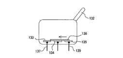
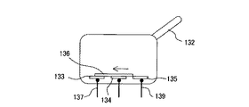
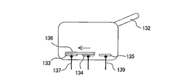
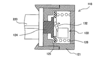
ここで、ピストン押圧部118について、その移動方向に沿った断面図である図4を参照して説明する。
Here, the
ピストン押圧部118は、駆動ロッド117(図3参照)による移動方向である矢印M方向における一端面に開口部121aが形成された押圧部本体121を有している。押圧部本体121は、他端面側が開放され、全体として筒状に構成されている。押圧部本体121の開放した他端面は蓋部材122によって塞がれており、これら押圧部本体121と蓋部材122とによって、ピストン押圧部118の、中空構造を有する筐体が構成されている。
The
押圧部本体121の外周面には、ピストン部材220のフランジ221(図3参照)と係合するための、互いに対向して配置された一対のフランジ保持部材123が、ピストン押圧部118の一端側から突出して設けられている。フランジ保持部材123の先端部には楔形のフランジ受け爪123aが一体に形成されており、このフランジ受け爪123aがフランジ221に係合する。
A pair of
ピストン押圧部220の中空部には、ピストン接触部材124と、可動板125と、コイルばね126と、検出スイッチ130と、が配置されている。
A
ピストン接触部材124は、平板部とその中央領域に設けられた凸部とを有しており、平板部がピストン押圧部118の中空部内に位置し、かつ凸部が開口部121aを介して押圧部本体121から突出する向きで、矢印M方向に移動自在に設けられている。ピストン押圧部118がピストン部材220を押圧するとき、凸部の先端面が、ピストン部材220の端面すなわちフランジ221を押圧する。
The
平板部の直径は開口部121aの直径よりも大きい。したがって、ピストン接触部材124の平板部の凸部を有する面が押圧部本体121の内面に当接することによって、押圧部本体121からのピストン接触部材124の最大突出量が規定される。ピストン接触部材124の凸部の高さは、ピストン接触部材124が押圧部本体121から最も突出した状態で、矢印M方向での凸部の先端面からフランジ受け爪123aまでの距離d1がピストン部材220のフランジ221の厚さよりも小さくなるように設定されている。
The diameter of the flat plate portion is larger than the diameter of the
可動板125は、ピストン接触部材124と接触可能に設けられたリング状の部材であり、ピストン接触部材124が接触した状態でピストン接触部材124が可動板125側へ変位することによって、ピストン接触部材124と一緒に変位する。また、可動板125は、可動板125と蓋部材122との間に設けられたコイルばね126によって、ピストン接触部材124に向けて付勢されている。
The
ただし、少なくともピストン接触部材124が押圧部本体121から最も突出した状態では可動板125がピストン接触部材124に接触しないように、押圧部本体121の内周面は、ピストン接触部材124が設けられた側の端部に、可動板125が当接する段差部を有している。この段差部は、ピストン押圧部118にフランジ221が支持されていないときに、可動板125がコイルばね126の付勢力でピストン接触部材124と接触しないように可動板125の位置を規制するストッパとして機能する。本実施形態では、段差部は、コイルばね126が最大たわみに達しない範囲で圧縮した状態で支持されるように設けられている。したがって、この状態でコイルばね126に作用している応力よりも大きい応力がコイルばね126に作用することによってコイルばね126をさらに圧縮させることが可能である。コイルばね126をさらに圧縮させることのできるような応力がピストン接触部材124に作用すると、ピストン接触部材126はさらに変位することができる。
However, the
検出スイッチ130は、DT(双投)形のマイクロスイッチであり、開閉動作する複数の接点(不図示)を収容したケース131と、接点機構を開閉動作させるためのアクチュエータ132と、を有する。ケース131は、不図示の取り付け部材によって押圧部本体121内の定位置に固定されている。
The
アクチュエータ132は、本実施形態ではレバー状の部材であり、不図示のばねによって先端部がピストン接触部材124に接触するように付勢されつつ、ケース131に対して回動可能に設けられている。したがって、アクチュエータ132はピストン接触部材124をその凸部が押圧部本体121から突出する向きに付勢している。これによって、ピストン部材220のフランジ221がフランジ保持部材123によって保持された状態では、ピストン接触部材124はピストン部材220のフランジ221と接触している。アクチュエータ132の形態は、レバーに限らず、押しボタンやスライド部材など、スイッチのアクチュエータとして用いられる任意の形態を適用することができる。
The
次に、本実施形態で用いた検出スイッチ130について図5A〜図5Dおよび図6を参照して説明する。
Next, the
図5Aに示すように、検出スイッチ130は、互いに電気的に独立して設けられた第1〜第3の固定接点133〜135と、各固定接点133〜135のうち少なくとも第2の固定接点134と電気的に接続するように各固定接点133〜135に対して移動可能に設けられた可動接点136と、をケース131内に有する。可動接点136は、不図示の動作機構を介してアクチュエータ132と連結されており、アクチュエータ132の回動に伴って、図5A〜図5Dに示した各状態をとる。
As shown in FIG. 5A, the
さらに、検出スイッチ130は、外部端子として、NO端子(常時開路端子)137、COM端子(共通端子)138、およびNC端子(常時閉路端子)139を有している。NO端子137は第1の固定接点133と電気的に接続されている。COM端子138は、第2の固定接点134と電気的に接続されている。NC端子139は、第3の固定接点135と電気的に接続されている。
Furthermore, the
本実施形態では、検出スイッチ130として、切り替えタイミングがショーティングタイプであるものを用いている。ショーティングタイプとは、切り替え前の接点とこれから切り替えようとする接点が、可動接点によって切り替え途中に短絡されるタイプをいう。以下に、検出スイッチ130の動作を説明する。
In the present embodiment, the
図5Aは、アクチュエータ132がFP(自由位置)にある状態を示している。この状態では、可動接点136は第2の固定接点134および第3の固定接点135と接触しているが、第1の固定接点133とは接触していない。したがって、NO端子137からの出力はオフ、NC端子139からの出力はオンとなっている。
FIG. 5A shows a state where the
アクチュエータ132に外力が加えられることによってアクチュエータ132が回動すると、図5Bに示すように、可動接点136は矢印方向へ移動し、第3の固定接点135と接触した状態を維持しつつ、第1の固定接点133と接触する。つまり、可動接点136は、すべての固定接点133〜135と接触する。可動接点136が第1の固定接点135と接触したときのアクチュエータ132の位置を、OP1(第1動作位置)という。この状態では、NO端子137からの出力およびNC端子139からの出力はどちらもオンとなっている。
When the
アクチュエータ132がさらに回動すると、図5Cに示すように、可動接点136もさらに矢印方向へ移動し、第3の固定接点135から離れるようになる。可動接点136が第3の固定接点135から離れる直前のアクチュエータ132の位置を、OP2(第2動作位置)という。可動接点136が第3の固定接点135から離れると、NC端子139からの出力はオフになる。可動接点136が第3の固定接点135から離れた後も、可動接点136は第1および第2の固定接点133,134との接触状態を維持しており、NO端子137からの出力はオンとなっている。
When the
アクチュエータ132がさらに回動し、TTP(動作限度位置)まで移動した状態を図5Dに示す。この状態では、可動接点136は第1および第2の固定接点133,134とのみ接触し、第3の固定接点135とは接触していない。したがって、NO端子137からの出力はオンであるが、NC端子139からの出力はオフとなっている。
FIG. 5D shows a state where the
上述した一連の動作におけるNO端子137からの出力およびNC端子139からの出力を、アクチュエータ132の位置を横軸にとって表したのが図6である。図6を参照すると、アクチュエータ132がFPからOP1およびOP2を経てTTPへ移動する間、NC端子139からの出力はFPからOP2までの間でオンであり、NO端子137からの出力はOP1からTTPまでの間でオンであることがわかる。したがって、OP1からOP2までの間では、NC端子139からの出力およびNO端子137からの出力はいずれもオンである。NO端子137およびNC端子139からの出力は注入制御ユニット101(図2参照)へ入力される。
FIG. 6 shows the output from the NO terminal 137 and the output from the
なお、アクチュエータ132に加わる外力が取り除かれると、不図示のばねの付勢力によってFPへ戻る。
When the external force applied to the
次に、上述した検出スイッチ130を利用した検出動作について説明する。
Next, a detection operation using the above-described
まず、図4に示すように、ピストン押圧部118にピストン部材220が装着される前は、検出スイッチ130のアクチュエータ132は、ピストン接触部材124をその凸部が押圧部本体121の開口部121aから突出する向きに付勢し、これによって、ピストン接触部材124は押圧部本体121の内面に押しつけられている。アクチュエータ132は、OP1には達しておらず、検出スイッチ130はNC端子139のみがオンになっている。
First, as shown in FIG. 4, before the
仮に、この段階でNO端子137およびNC端子139からの出力がいずれもオフであると、注入制御ユニット101(図2参照)は、検出スイッチ130等に異常が発生したと判断し、エラーが発生した旨をタッチパネル104(図2参照)に表示させる。また、NO端子137およびNC端子139からの出力がいずれもONである場合も、注入制御ユニット101(図2参照)は、検出スイッチ130等に異常が発生したと判断し、エラーが発生した旨をタッチパネル104に表示させる。
If the outputs from the NO terminal 137 and the
この段階では、NC端子139のみがオンとなっていればよいため、アクチュエータ132がFPにあるように、アクチュエータ132とピストン接触部材124との位置関係が設定されていてもよい。
At this stage, since only the
次いで、図3に示すように、注入ヘッド110に、薬液が充填された薬液シリンジ200P、200Cを装着する。具体的には、凹部114の第2の部分114aに薬液シリンジ200P(200C)のシリンダ部材210を保持させるとともに、図7Aに示すように、ピストン部材220のフランジ221をピストン押圧部118のフランジ保持部材123に係合させる。ピストン押圧部118にピストン部材220が装着されると、ピストン接触部材124は、フランジ221によってピストン押圧部118内に押し込まれる。ピストン接触部材124が押し込まれることによって、アクチュエータ132は、OP1を超えるがOP2へは達しない位置まで矢印方向に回動する。
Next, as shown in FIG. 3, chemical liquid syringes 200 </ b> P and 200 </ b> C filled with the chemical liquid are attached to the
これによって、検出スイッチ130は、NC端子139だけでなくNO端子137からの出力もオンになる。NO端子137からの出力がオンになったとき、注入制御ユニット101は、薬液シリンジ200P(200C)が正常に装着されたと判断し、その後の、操作者からの入力操作等にしたがって注入ヘッド110の動作を制御する。一方、NC端子137からの出力がオフのままであれば、注入制御ユニット101は、薬液シリンジ200P(200C)が装着されていないと判断し、その旨をタッチパネル104に表示させる。
As a result, the
この状態では、ピストン接触部材124は、可動板125に接触していてもよいし、可動板125から離れていてもよい。ただし、ピストン接触部材124の凸部は押圧部本体121の開口部121aから突出した位置にある。
In this state, the
ピストン押圧部118にピストン部材220が装着された状態で、駆動ロッド117(図3参照)を前進させると、ピストン部材220にはピストン押圧部118による圧力が作用する。この圧力によって、ピストン部材220がシリンダ部材210内に押し込まれ、シリンダ部材210内に充填されている薬液がシリンダ部材210から押し出される。
When the drive rod 117 (see FIG. 3) is advanced in a state where the
ピストン押圧部118がピストン部材220をシリンダ部材210内に押し込むことによって、ピストン接触部材124は、押圧部本体121内に押し込まれる向きの反力をピストン部材220から受ける。この反力によって、ピストン接触部材124は、コイルばね126を圧縮させる向きに可動板125を押圧する。コイルばね126は、前述したように、押圧部本体121に設けられた段差部をストッパとして支持されているので、図8のグラフに示すように、ある一定の応力が作用するまでは、コイルばね126のたわみは一定である。コイルばね126に作用する応力が、ある一定の応力を超えると、図7Bに示すように、ピストン接触部材124は、可動板125を介してコイルばね126をさらに圧縮しながら、押圧部本体121内に押し込まれる。ピストン接触部材124が押し込まれることによって、その押し込み量に応じてアクチュエータ132は矢印方向にさらに回動する。
When the
ピストン接触部材124の押し込み量は、ピストン部材220からの反力の大きさ、すなわちピストン部材220に作用する応力の大きさに依存し、その応力が大きいほどピストン接触部材124の押し込み量は大きくなる。ピストン部材220からの反力は、薬液シリンジ200P、200Cに作用する注入圧力に対応する。ここで、ピストン接触部材124の、押圧部本体121の端面からの突出量は、ピストン接触部材124の先端面が押圧部本体121の端面と同一平面上に位置するまでピストン接触部材124がピストン部材220によって押し込まれる間に、アクチュエータ132がOP2に達するように設定されている。
The pushing amount of the
また、コイルばね126のばね特性は、ピストン接触部材124がピストン部材220に加える応力が、予め決められた所定の応力となったとき、すなわち注入圧力が予め決められた注入圧力となったときに、アクチュエータ132がOP2に達するように設定されている。本実施形態では、注入圧力が、薬液シリンジ200P、200Cを破損に至らせるおそれのある注入圧力である、1.18×10⁵Pa(1.2kg/cm2)となるときに、アクチュエータ132がOP2に達するように、コイルばね126のばね特性を設定している。Further, the spring characteristic of the
アクチュエータ132がOP2に達すると、NC端子139からの出力はオフになる。NC端子139からの出力がオフになったとき、注入制御ユニット101は、注入圧力が限界圧力に達したと判断し、注入ヘッド110の動作を停止するとともに、タッチパネル104に、圧力異常が発生した旨を表示する。
When the
以上のように、本実施形態では、ピストン部材220に圧力を加えることによって変位することのできるピストン接触部材124と、このピストン接触部材124の変位に基づいて、ピストン接触部材124がフランジ221から受ける力が予め決められた力に達する前と達した後で、開閉状態が切り替わる検出スイッチ130をピストン押圧部118に内蔵している。これにより、ロードセルを用いることなく、薬液注入時に薬液シリンジ200P、200Cに作用する圧力異常を検出することができる。その結果、簡易な構成で安価な薬液注入装置100が提供される。しかも、ピストン押圧部118にピストン部材220が保持された後、ピストン接触部材124は、ピストン部材220から受ける力がある一定の力に達する前の初期段階では変位しないので、検出スイッチ130による圧力異常の検出を安定して行うことができる。
As described above, in this embodiment, the
さらに、ピストン接触部材124は、ピストン押圧部118がピストン部材220のフランジ221を保持する前と保持した後でも変位し、検出スイッチ130は、ピストン部材220に加える圧力に応じたピストン接触部材124の変位とは別に、ピストン部材220の着脱によるピストン接触部材124の変位によっても、開閉状態が切り替わる。したがって、本実施形態の薬液注入装置100は、圧力異常だけでなく薬液シリンジ200P、200Cが正常に着脱されたか否かも検出することができる。その結果、薬液シリンジ200P、200Cが不完全に装着された状態で薬液注入動作を実施することによる、薬液シリンジ200P、200Cの破損をも防止することができる。
Further, the
本実施形態では、押圧部本体121に段差部を設け、これによって圧縮ばね126を圧縮させた状態で支持した例を示したが、段差部を設けず、外力が作用しない状態で圧縮ばね126を支持してもよい。この場合は、コイルばね126の付勢力に抗してピストン接触部材124を押し込みながら、ピストン押圧部118にピストン部材220を保持させることができるように、コイルばね126のばね定数を設定する。あるいは、スペース的に余裕がある場合は、ピストン部材220を保持したときにピストン接触部材124が変位してもコイルばね126が圧縮しないように、ピストン接触部材124、可動板125およびコイルばね126の寸法を設定する。
In the present embodiment, the step portion is provided in the pressing portion
また、本実施形態では、検出スイッチ130としてショーティングタイプのものを用いたが、ノンショーティングタイプのものを用いることもできる。ノンショーティングタイプの検出スイッチは、図9に示すように、アクチュエータ132の位置がOP1とOP2の間にあるとき、可動接点136は第1の固定接点133および第3の固定接点135のいずれとも接触しない。その切り替えタイミングは図10に示すとおりであり、ショーティングタイプとの違いは、OP1とOP2との間でNC端子139からの出力およびNO端子137からの出力がいずれもオフとなることである。
In this embodiment, a shorting type switch is used as the
ノンショーティングタイプの検出スイッチを用いた場合、薬液シリンジ200P(200C)が装着されたか否かの検出は、NC端子139からの出力がオンからオフになったことによって行われる。また、圧力異常の検出は、NO端子137からの出力がオンになったことによって行われる。
When the non-shorting type detection switch is used, whether or not the
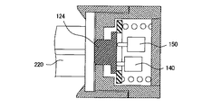
また、本実施形態では、双投形の1つの検出スイッチ130を用いて、薬液シリンジ200P(200C)の着脱、および薬液注入時の圧力異常を検出したが、図11に示すように、単投形の2つの検出スイッチ140、150を用いることもできる。これら検出スイッチ140、150は、図4に示した検出スイッチ130に置き換えられて、前述したピストン押圧部118内に設置される。
Further, in this embodiment, a single-throw
単投形の検出スイッチ140、150では、そのアクチュエータは1つのOPを有している。また、単投形の検出スイッチ140、150はさらに、接触形式がNO(常時開路)形とNC(常時閉路)形とに分けられる。 In the single-throw detection switches 140 and 150, the actuator has one OP. The single throw type detection switches 140 and 150 are further classified into a NO (normally open) type and an NC (normally closed) type.
例えば、一方の検出スイッチ140をNO形とするとともに、他方の検出スイッチ150をNC形とした場合、各検出スイッチ140、150を次のように設置する。NO形の検出スイッチ140は、図12Aに示すようにピストン部材220が装着されたときにピストン接触部材124の変位によってアクチュエータがOPを超える位置まで移動するように設置する。NC形の検出スイッチ150は、ピストン部材220が装着されただけではアクチュエータがOPに達しないが、図12Bに示すように、検出すべき圧力異常が発生したときのピストン接触部材124の変位によってアクチュエータがOPに達する位置に設置する。このように各検出スイッチ140、150を設置することで、前述したショーティング形の検出スイッチ130を用いた場合と同じシーケンスで、薬液シリンジの着脱、および薬液注入時の圧力異常を検出することができる。
For example, when one
あるいは、上記のNO形の検出スイッチ140の位置とNC形の検出スイッチ150の位置を入れ替えれば、前述したノンショーティング形の検出スイッチを用いた場合と同様のシーケンスで、薬液シリンジの着脱、および薬液注入時の圧力異常を検出することができる。
Alternatively, if the position of the NO-
各検出スイッチ140、150は、どちらもNO形であってもよいし、NC形であってもよい。いずれの場合も、上記のようにNO形とNC形を組み合わせた場合と同様に各検出スイッチ140、150を設置し、それに応じて検出のためのシーケンスを適宜変更することで、薬液シリンジの着脱、および薬液注入時の圧力異常を検出することができる。 Each of the detection switches 140 and 150 may be an NO type or an NC type. In any case, as in the case where the NO type and NC type are combined as described above, the detection switches 140 and 150 are installed, and the detection sequence is appropriately changed accordingly. , And a pressure abnormality at the time of injecting a chemical solution can be detected.
図13に、本発明の他の実施形態によるピストン押圧部の斜視図を示す。 FIG. 13 shows a perspective view of a piston pressing portion according to another embodiment of the present invention.
図13に示すピストン押圧部160の、前述した実施形態と相違する点は、フランジ保持部材163の構造、およびピストン押圧部160を進退移動させるための駆動ロッド165に対する、薬液シリンジのピストン部材の保持位置である。
The piston
前述した実施形態では、本発明におけるフランジ保持部は、ピストン押圧部の両側部に設けられたピストン保持部材を有していたが、本実施形態では、ピストン部材のフランジが設けられた部分が載せられることによって下方から支持する受け部材としてフランジ保持部材163が構成されている。このように、フランジ保持部は、ピストン押圧部160が進退移動するのと一緒にピストン部材を進退移動させることができる構成であれば任意の構成を有するものとすることができる。
In the embodiment described above, the flange holding portion in the present invention has the piston holding members provided on both sides of the piston pressing portion. However, in this embodiment, the portion of the piston member provided with the flange is mounted. Accordingly, a
また、前述した実施形態では、ピストン押圧部は、駆動ロッド165と同軸上でピストン部材を保持するものであったが、本実施形態では、ピストン押圧部160は、ピストン駆動ロッド165の軸心と異なる位置でピストン部材を保持する。
In the above-described embodiment, the piston pressing portion is configured to hold the piston member coaxially with the
その他、ピストン押圧部160が中空構造の筐体161を有していること、その筐体161内に、ピストン接触部材162が先端部を突出させて変位可能に設けられていること、および前述した実施形態で説明したようなスイッチ機構が筐体161内に設けられていること等は、前述した実施形態と同様である。
In addition, the
本発明は、上述した各実施形態に限定されるものではなく、種々の変更を加えることができる。例えば、注入ヘッドに装着できる薬液シリンジの数は、2本に限らず、1本でもよいし3本以上であってもよい。凹部114、および駆動ロッド117等は、装着される薬液シリンジの数に応じた数だけ設けられる。また、注入ヘッド110に装着できる薬液シリンジのサイズも任意であり、凹部114のサイズや駆動ロッド117のストローク等は、装着すべき薬液シリンジのサイズに適合するように設定される。複数の薬液シリンジを装着する場合、各薬液シリンジのサイズは互いに異なるものであってもよい。
The present invention is not limited to the above-described embodiments, and various modifications can be made. For example, the number of chemical syringes that can be attached to the injection head is not limited to two, and may be one or three or more. The
さらに、上述した実施形態では、MRI装置に適用したものとして説明したが、本発明は、透視撮像装置がCTスキャナ装置、PET装置、アンギオ装置、あるいはMRA装置であっても適用することができる。 Furthermore, in the above-described embodiments, the description has been made assuming that the present invention is applied to an MRI apparatus, but the present invention can be applied even if the fluoroscopic imaging apparatus is a CT scanner apparatus, a PET apparatus, an angio apparatus, or an MRA apparatus.
Claims (7)
前記シリンダ部材を着脱自在に保持することによって前記薬液シリンジが装着されるシリンジ装着部と、
前記シリンジ装着部に装着された薬液シリンジの前記ピストン部材を押圧することによって、前記ピストン部材を前記シリンダ部材内に押し込むピストン押圧部と、
を備え、
前記ピストン押圧部は、
前記ピストン部材の端部に設けられているフランジを保持するフランジ保持部と、
前記フランジ保持部に保持されたフランジと接触するように突出しており、前記フランジが保持されることによって変位し、かつ、前記ピストン押圧部が前記ピストン部材を押し込むことによって、前記フランジから受ける力でさらに変位することができるように設けられたピストン接触部材と、
前記ピストン接触部材の変位に応じて、前記フランジを保持する前と保持した後、および前記フランジから受ける力が予め決められた力に達する前と達した後で、それぞれ開閉状態が切り替わるスイッチ機構と、
一端に設けられた開口部から前記ピストン接触部材を突出させて前記ピストン接触部材を変位可能に収容する中空構造の筐体と、
を有し、
前記スイッチ機構は、前記ピストン接触部材の変位に応じて作動されるアクチュエータおよび前記アクチュエータを付勢するばねを備えた、前記筐体の内部に固定された1つまたは2つのスイッチを有する薬液注入装置。A chemical liquid injection device for operating a chemical liquid syringe having a cylinder member filled with a chemical liquid and a piston member slidably inserted into the cylinder member to inject the chemical liquid into an injection target,
A syringe mounting portion on which the chemical syringe is mounted by detachably holding the cylinder member;
A piston pressing portion for pressing the piston member into the cylinder member by pressing the piston member of the chemical syringe mounted on the syringe mounting portion;
With
The piston pressing part is
A flange holding portion for holding a flange provided at an end of the piston member;
It protrudes so as to come into contact with the flange held by the flange holding portion, is displaced by holding the flange, and is received by the force received from the flange by the piston pressing portion pushing the piston member. A piston contact member provided so as to be further displaceable;
A switch mechanism that switches between open and closed states before and after holding the flange and before and after the force received from the flange reaches a predetermined force according to the displacement of the piston contact member; ,
A hollow housing that projects the piston contact member from an opening provided at one end and accommodates the piston contact member in a displaceable manner;
I have a,
The switching mechanism, said piston contacting with a spring for urging the actuator and the actuator is operated in response to displacement of the member, the liquid injector to have a one or two switches secured to the inside of the housing apparatus.
前記筐体の内部に、前記ピストン接触部材が接触した状態で前記ピストン接触部材が前記フランジから力を受けて変位することによって、前記ピストン接触部材と一緒に変位可能に設けられた可動部材と、
前記可動部材を前記ピストン接触部材に向けて付勢する付勢部材と、
前記フランジ保持部に前記フランジが保持されていないときに、前記可動部材が前記付勢部材の付勢力で前記ピストン接触部材と接触しないように、前記可動部材の位置を規制するストッパと、
をさらに有する、請求項1に記載の薬液注入装置。The piston pressing part is
Inside the front Kikatamitai by said piston contacting member is displaced by a force from the flange in a state where the piston contact member is in contact, a movable member provided to be displaceable together with the piston contact member ,
A biasing member that biases the movable member toward the piston contact member;
A stopper that regulates the position of the movable member so that the movable member does not come into contact with the piston contact member by the biasing force of the biasing member when the flange is not held by the flange holding portion;
The chemical injection device according to claim 1, further comprising:
Priority Applications (1)
| Application Number | Priority Date | Filing Date | Title |
|---|---|---|---|
| JP2008522644A JP5097705B2 (en) | 2006-06-29 | 2007-06-29 | Chemical injection device |
Applications Claiming Priority (4)
| Application Number | Priority Date | Filing Date | Title |
|---|---|---|---|
| JP2006179458 | 2006-06-29 | ||
| JP2006179458 | 2006-06-29 | ||
| JP2008522644A JP5097705B2 (en) | 2006-06-29 | 2007-06-29 | Chemical injection device |
| PCT/JP2007/063082 WO2008001881A1 (en) | 2006-06-29 | 2007-06-29 | Chemical liquid injection device |
Publications (2)
| Publication Number | Publication Date |
|---|---|
| JPWO2008001881A1 JPWO2008001881A1 (en) | 2009-11-26 |
| JP5097705B2 true JP5097705B2 (en) | 2012-12-12 |
Family
ID=38845644
Family Applications (1)
| Application Number | Title | Priority Date | Filing Date |
|---|---|---|---|
| JP2008522644A Active JP5097705B2 (en) | 2006-06-29 | 2007-06-29 | Chemical injection device |
Country Status (2)
| Country | Link |
|---|---|
| JP (1) | JP5097705B2 (en) |
| WO (1) | WO2008001881A1 (en) |
Families Citing this family (6)
| Publication number | Priority date | Publication date | Assignee | Title |
|---|---|---|---|---|
| CH701492A1 (en) * | 2009-07-20 | 2011-01-31 | Tecpharma Licensing Ag | Delivery device with a means for detecting pressure changes. |
| CN102724947A (en) * | 2010-01-29 | 2012-10-10 | 松下电器产业株式会社 | Syringe drive device and syringe drive method |
| US8479595B2 (en) | 2010-10-20 | 2013-07-09 | Medtronic Minimed, Inc. | Sensor assembly and medical device incorporating same |
| US8495918B2 (en) * | 2010-10-20 | 2013-07-30 | Medtronic Minimed, Inc. | Sensor assembly and medical device incorporating same |
| US8474332B2 (en) | 2010-10-20 | 2013-07-02 | Medtronic Minimed, Inc. | Sensor assembly and medical device incorporating same |
| CN110652628B (en) * | 2013-12-06 | 2021-06-29 | 尤尼特拉克特注射器控股有限公司 | Drive mechanism for drug delivery pump with integrated status indication |
Citations (8)
| Publication number | Priority date | Publication date | Assignee | Title |
|---|---|---|---|---|
| JPS5580027A (en) * | 1978-12-13 | 1980-06-16 | Nippon Air Brake Co Ltd | Fluid pressure switch |
| JPH03129619A (en) * | 1989-10-13 | 1991-06-03 | Sumitomo Electric Ind Ltd | Pressure switch |
| JPH09129087A (en) * | 1995-11-02 | 1997-05-16 | Mic Electron Co | Change-over lever switch |
| US5879360A (en) * | 1994-01-21 | 1999-03-09 | The University Of Melbourne | Syringe pumps |
| GB2356349A (en) * | 1999-10-08 | 2001-05-23 | Sarmed Ltd | Syringe actuator assembly |
| JP2003520625A (en) * | 1999-07-29 | 2003-07-08 | アラリス メディカル システムズ インコーポレイテッド | Syringe plunger driver system and method |
| US20030229311A1 (en) * | 2002-06-05 | 2003-12-11 | Matthew G. Morris | Syringe plunger driver system |
| JP2004236734A (en) * | 2003-02-04 | 2004-08-26 | Nemoto Kyorindo:Kk | Medical solution injection system |
-
2007
- 2007-06-29 WO PCT/JP2007/063082 patent/WO2008001881A1/en active Application Filing
- 2007-06-29 JP JP2008522644A patent/JP5097705B2/en active Active
Patent Citations (8)
| Publication number | Priority date | Publication date | Assignee | Title |
|---|---|---|---|---|
| JPS5580027A (en) * | 1978-12-13 | 1980-06-16 | Nippon Air Brake Co Ltd | Fluid pressure switch |
| JPH03129619A (en) * | 1989-10-13 | 1991-06-03 | Sumitomo Electric Ind Ltd | Pressure switch |
| US5879360A (en) * | 1994-01-21 | 1999-03-09 | The University Of Melbourne | Syringe pumps |
| JPH09129087A (en) * | 1995-11-02 | 1997-05-16 | Mic Electron Co | Change-over lever switch |
| JP2003520625A (en) * | 1999-07-29 | 2003-07-08 | アラリス メディカル システムズ インコーポレイテッド | Syringe plunger driver system and method |
| GB2356349A (en) * | 1999-10-08 | 2001-05-23 | Sarmed Ltd | Syringe actuator assembly |
| US20030229311A1 (en) * | 2002-06-05 | 2003-12-11 | Matthew G. Morris | Syringe plunger driver system |
| JP2004236734A (en) * | 2003-02-04 | 2004-08-26 | Nemoto Kyorindo:Kk | Medical solution injection system |
Also Published As
| Publication number | Publication date |
|---|---|
| JPWO2008001881A1 (en) | 2009-11-26 |
| WO2008001881A1 (en) | 2008-01-03 |
Similar Documents
| Publication | Publication Date | Title |
|---|---|---|
| JP5097705B2 (en) | Chemical injection device | |
| JP4708189B2 (en) | Chemical solution injection system for detecting attachment / detachment of a chemical solution syringe to / from a chemical solution injection device | |
| JP4338447B2 (en) | Chemical injection system | |
| JP4286019B2 (en) | Chemical injection system | |
| US9943680B2 (en) | Systems and method for assessing functionality of dual check valve arrangements in medical tubing sets | |
| EP2337595B1 (en) | Power injector syringe clamp assembly with rfid antenna | |
| US20050049556A1 (en) | Liquid injector in which a device for detecting the pressure exerted upon the liquid syringe piston is not arranged on a movable part | |
| JP4833984B2 (en) | Chemical injection system | |
| US20200121848A1 (en) | Injector device | |
| JPWO2006057089A1 (en) | Chemical injection system | |
| JP6998897B2 (en) | Injection device drive unit with block device | |
| WO2008007674A1 (en) | Chemical liquid loading device | |
| US8496612B2 (en) | Adapter for power injections | |
| WO2006054650A1 (en) | Controller unit | |
| WO2007114447A1 (en) | Medical liquid injecting device | |
| JP4044780B2 (en) | Injection head | |
| JP4447243B2 (en) | Chemical injection system | |
| US7192417B2 (en) | Injectors and syringe interfaces for syringes of variable size | |
| JPWO2007116841A1 (en) | Chemical injection system | |
| JP4481585B2 (en) | Chemical injection device | |
| JPWO2011145464A1 (en) | Injection head and chemical injection system | |
| JP4414128B2 (en) | Chemical injection device |
Legal Events
| Date | Code | Title | Description |
|---|---|---|---|
| A621 | Written request for application examination |
Free format text: JAPANESE INTERMEDIATE CODE: A621 Effective date: 20100617 |
|
| A131 | Notification of reasons for refusal |
Free format text: JAPANESE INTERMEDIATE CODE: A131 Effective date: 20120509 |
|
| A521 | Request for written amendment filed |
Free format text: JAPANESE INTERMEDIATE CODE: A523 Effective date: 20120706 |
|
| TRDD | Decision of grant or rejection written | ||
| A01 | Written decision to grant a patent or to grant a registration (utility model) |
Free format text: JAPANESE INTERMEDIATE CODE: A01 Effective date: 20120828 |
|
| A01 | Written decision to grant a patent or to grant a registration (utility model) |
Free format text: JAPANESE INTERMEDIATE CODE: A01 |
|
| A61 | First payment of annual fees (during grant procedure) |
Free format text: JAPANESE INTERMEDIATE CODE: A61 Effective date: 20120924 |
|
| R150 | Certificate of patent or registration of utility model |
Free format text: JAPANESE INTERMEDIATE CODE: R150 Ref document number: 5097705 Country of ref document: JP Free format text: JAPANESE INTERMEDIATE CODE: R150 |
|
| FPAY | Renewal fee payment (event date is renewal date of database) |
Free format text: PAYMENT UNTIL: 20150928 Year of fee payment: 3 |
|
| R250 | Receipt of annual fees |
Free format text: JAPANESE INTERMEDIATE CODE: R250 |
|
| R250 | Receipt of annual fees |
Free format text: JAPANESE INTERMEDIATE CODE: R250 |
|
| R250 | Receipt of annual fees |
Free format text: JAPANESE INTERMEDIATE CODE: R250 |
|
| S802 | Written request for registration of partial abandonment of right |
Free format text: JAPANESE INTERMEDIATE CODE: R311802 |
|
| R350 | Written notification of registration of transfer |
Free format text: JAPANESE INTERMEDIATE CODE: R350 |
|
| R250 | Receipt of annual fees |
Free format text: JAPANESE INTERMEDIATE CODE: R250 |
|
| R250 | Receipt of annual fees |
Free format text: JAPANESE INTERMEDIATE CODE: R250 |