JP5096362B2 - Mounting mat for pollution control - Google Patents
Mounting mat for pollution control Download PDFInfo
- Publication number
- JP5096362B2 JP5096362B2 JP2008545750A JP2008545750A JP5096362B2 JP 5096362 B2 JP5096362 B2 JP 5096362B2 JP 2008545750 A JP2008545750 A JP 2008545750A JP 2008545750 A JP2008545750 A JP 2008545750A JP 5096362 B2 JP5096362 B2 JP 5096362B2
- Authority
- JP
- Japan
- Prior art keywords
- fibers
- pollution control
- mat
- fiber
- mixture
- Prior art date
- Legal status (The legal status is an assumption and is not a legal conclusion. Google has not performed a legal analysis and makes no representation as to the accuracy of the status listed.)
- Expired - Fee Related
Links
Images
Classifications
-
- D—TEXTILES; PAPER
- D04—BRAIDING; LACE-MAKING; KNITTING; TRIMMINGS; NON-WOVEN FABRICS
- D04H—MAKING TEXTILE FABRICS, e.g. FROM FIBRES OR FILAMENTARY MATERIAL; FABRICS MADE BY SUCH PROCESSES OR APPARATUS, e.g. FELTS, NON-WOVEN FABRICS; COTTON-WOOL; WADDING ; NON-WOVEN FABRICS FROM STAPLE FIBRES, FILAMENTS OR YARNS, BONDED WITH AT LEAST ONE WEB-LIKE MATERIAL DURING THEIR CONSOLIDATION
- D04H1/00—Non-woven fabrics formed wholly or mainly of staple fibres or like relatively short fibres
- D04H1/40—Non-woven fabrics formed wholly or mainly of staple fibres or like relatively short fibres from fleeces or layers composed of fibres without existing or potential cohesive properties
- D04H1/42—Non-woven fabrics formed wholly or mainly of staple fibres or like relatively short fibres from fleeces or layers composed of fibres without existing or potential cohesive properties characterised by the use of certain kinds of fibres insofar as this use has no preponderant influence on the consolidation of the fleece
- D04H1/4209—Inorganic fibres
- D04H1/4218—Glass fibres
-
- D—TEXTILES; PAPER
- D04—BRAIDING; LACE-MAKING; KNITTING; TRIMMINGS; NON-WOVEN FABRICS
- D04H—MAKING TEXTILE FABRICS, e.g. FROM FIBRES OR FILAMENTARY MATERIAL; FABRICS MADE BY SUCH PROCESSES OR APPARATUS, e.g. FELTS, NON-WOVEN FABRICS; COTTON-WOOL; WADDING ; NON-WOVEN FABRICS FROM STAPLE FIBRES, FILAMENTS OR YARNS, BONDED WITH AT LEAST ONE WEB-LIKE MATERIAL DURING THEIR CONSOLIDATION
- D04H1/00—Non-woven fabrics formed wholly or mainly of staple fibres or like relatively short fibres
- D04H1/40—Non-woven fabrics formed wholly or mainly of staple fibres or like relatively short fibres from fleeces or layers composed of fibres without existing or potential cohesive properties
- D04H1/42—Non-woven fabrics formed wholly or mainly of staple fibres or like relatively short fibres from fleeces or layers composed of fibres without existing or potential cohesive properties characterised by the use of certain kinds of fibres insofar as this use has no preponderant influence on the consolidation of the fleece
- D04H1/4209—Inorganic fibres
-
- D—TEXTILES; PAPER
- D04—BRAIDING; LACE-MAKING; KNITTING; TRIMMINGS; NON-WOVEN FABRICS
- D04H—MAKING TEXTILE FABRICS, e.g. FROM FIBRES OR FILAMENTARY MATERIAL; FABRICS MADE BY SUCH PROCESSES OR APPARATUS, e.g. FELTS, NON-WOVEN FABRICS; COTTON-WOOL; WADDING ; NON-WOVEN FABRICS FROM STAPLE FIBRES, FILAMENTS OR YARNS, BONDED WITH AT LEAST ONE WEB-LIKE MATERIAL DURING THEIR CONSOLIDATION
- D04H1/00—Non-woven fabrics formed wholly or mainly of staple fibres or like relatively short fibres
- D04H1/40—Non-woven fabrics formed wholly or mainly of staple fibres or like relatively short fibres from fleeces or layers composed of fibres without existing or potential cohesive properties
- D04H1/42—Non-woven fabrics formed wholly or mainly of staple fibres or like relatively short fibres from fleeces or layers composed of fibres without existing or potential cohesive properties characterised by the use of certain kinds of fibres insofar as this use has no preponderant influence on the consolidation of the fleece
- D04H1/4382—Stretched reticular film fibres; Composite fibres; Mixed fibres; Ultrafine fibres; Fibres for artificial leather
- D04H1/43835—Mixed fibres, e.g. at least two chemically different fibres or fibre blends
-
- D—TEXTILES; PAPER
- D04—BRAIDING; LACE-MAKING; KNITTING; TRIMMINGS; NON-WOVEN FABRICS
- D04H—MAKING TEXTILE FABRICS, e.g. FROM FIBRES OR FILAMENTARY MATERIAL; FABRICS MADE BY SUCH PROCESSES OR APPARATUS, e.g. FELTS, NON-WOVEN FABRICS; COTTON-WOOL; WADDING ; NON-WOVEN FABRICS FROM STAPLE FIBRES, FILAMENTS OR YARNS, BONDED WITH AT LEAST ONE WEB-LIKE MATERIAL DURING THEIR CONSOLIDATION
- D04H1/00—Non-woven fabrics formed wholly or mainly of staple fibres or like relatively short fibres
- D04H1/40—Non-woven fabrics formed wholly or mainly of staple fibres or like relatively short fibres from fleeces or layers composed of fibres without existing or potential cohesive properties
- D04H1/42—Non-woven fabrics formed wholly or mainly of staple fibres or like relatively short fibres from fleeces or layers composed of fibres without existing or potential cohesive properties characterised by the use of certain kinds of fibres insofar as this use has no preponderant influence on the consolidation of the fleece
- D04H1/4382—Stretched reticular film fibres; Composite fibres; Mixed fibres; Ultrafine fibres; Fibres for artificial leather
- D04H1/43838—Ultrafine fibres, e.g. microfibres
-
- D—TEXTILES; PAPER
- D04—BRAIDING; LACE-MAKING; KNITTING; TRIMMINGS; NON-WOVEN FABRICS
- D04H—MAKING TEXTILE FABRICS, e.g. FROM FIBRES OR FILAMENTARY MATERIAL; FABRICS MADE BY SUCH PROCESSES OR APPARATUS, e.g. FELTS, NON-WOVEN FABRICS; COTTON-WOOL; WADDING ; NON-WOVEN FABRICS FROM STAPLE FIBRES, FILAMENTS OR YARNS, BONDED WITH AT LEAST ONE WEB-LIKE MATERIAL DURING THEIR CONSOLIDATION
- D04H1/00—Non-woven fabrics formed wholly or mainly of staple fibres or like relatively short fibres
- D04H1/40—Non-woven fabrics formed wholly or mainly of staple fibres or like relatively short fibres from fleeces or layers composed of fibres without existing or potential cohesive properties
- D04H1/44—Non-woven fabrics formed wholly or mainly of staple fibres or like relatively short fibres from fleeces or layers composed of fibres without existing or potential cohesive properties the fleeces or layers being consolidated by mechanical means, e.g. by rolling
- D04H1/46—Non-woven fabrics formed wholly or mainly of staple fibres or like relatively short fibres from fleeces or layers composed of fibres without existing or potential cohesive properties the fleeces or layers being consolidated by mechanical means, e.g. by rolling by needling or like operations to cause entanglement of fibres
-
- D—TEXTILES; PAPER
- D04—BRAIDING; LACE-MAKING; KNITTING; TRIMMINGS; NON-WOVEN FABRICS
- D04H—MAKING TEXTILE FABRICS, e.g. FROM FIBRES OR FILAMENTARY MATERIAL; FABRICS MADE BY SUCH PROCESSES OR APPARATUS, e.g. FELTS, NON-WOVEN FABRICS; COTTON-WOOL; WADDING ; NON-WOVEN FABRICS FROM STAPLE FIBRES, FILAMENTS OR YARNS, BONDED WITH AT LEAST ONE WEB-LIKE MATERIAL DURING THEIR CONSOLIDATION
- D04H13/00—Other non-woven fabrics
-
- D—TEXTILES; PAPER
- D04—BRAIDING; LACE-MAKING; KNITTING; TRIMMINGS; NON-WOVEN FABRICS
- D04H—MAKING TEXTILE FABRICS, e.g. FROM FIBRES OR FILAMENTARY MATERIAL; FABRICS MADE BY SUCH PROCESSES OR APPARATUS, e.g. FELTS, NON-WOVEN FABRICS; COTTON-WOOL; WADDING ; NON-WOVEN FABRICS FROM STAPLE FIBRES, FILAMENTS OR YARNS, BONDED WITH AT LEAST ONE WEB-LIKE MATERIAL DURING THEIR CONSOLIDATION
- D04H5/00—Non woven fabrics formed of mixtures of relatively short fibres and yarns or like filamentary material of substantial length
- D04H5/02—Non woven fabrics formed of mixtures of relatively short fibres and yarns or like filamentary material of substantial length strengthened or consolidated by mechanical methods, e.g. needling
-
- D—TEXTILES; PAPER
- D04—BRAIDING; LACE-MAKING; KNITTING; TRIMMINGS; NON-WOVEN FABRICS
- D04H—MAKING TEXTILE FABRICS, e.g. FROM FIBRES OR FILAMENTARY MATERIAL; FABRICS MADE BY SUCH PROCESSES OR APPARATUS, e.g. FELTS, NON-WOVEN FABRICS; COTTON-WOOL; WADDING ; NON-WOVEN FABRICS FROM STAPLE FIBRES, FILAMENTS OR YARNS, BONDED WITH AT LEAST ONE WEB-LIKE MATERIAL DURING THEIR CONSOLIDATION
- D04H5/00—Non woven fabrics formed of mixtures of relatively short fibres and yarns or like filamentary material of substantial length
- D04H5/12—Glass fibres
-
- F—MECHANICAL ENGINEERING; LIGHTING; HEATING; WEAPONS; BLASTING
- F01—MACHINES OR ENGINES IN GENERAL; ENGINE PLANTS IN GENERAL; STEAM ENGINES
- F01N—GAS-FLOW SILENCERS OR EXHAUST APPARATUS FOR MACHINES OR ENGINES IN GENERAL; GAS-FLOW SILENCERS OR EXHAUST APPARATUS FOR INTERNAL COMBUSTION ENGINES
- F01N3/00—Exhaust or silencing apparatus having means for purifying, rendering innocuous, or otherwise treating exhaust
- F01N3/08—Exhaust or silencing apparatus having means for purifying, rendering innocuous, or otherwise treating exhaust for rendering innocuous
- F01N3/10—Exhaust or silencing apparatus having means for purifying, rendering innocuous, or otherwise treating exhaust for rendering innocuous by thermal or catalytic conversion of noxious components of exhaust
- F01N3/24—Exhaust or silencing apparatus having means for purifying, rendering innocuous, or otherwise treating exhaust for rendering innocuous by thermal or catalytic conversion of noxious components of exhaust characterised by constructional aspects of converting apparatus
- F01N3/28—Construction of catalytic reactors
- F01N3/2839—Arrangements for mounting catalyst support in housing, e.g. with means for compensating thermal expansion or vibration
- F01N3/2853—Arrangements for mounting catalyst support in housing, e.g. with means for compensating thermal expansion or vibration using mats or gaskets between catalyst body and housing
- F01N3/2864—Arrangements for mounting catalyst support in housing, e.g. with means for compensating thermal expansion or vibration using mats or gaskets between catalyst body and housing the mats or gaskets comprising two or more insulation layers
-
- F—MECHANICAL ENGINEERING; LIGHTING; HEATING; WEAPONS; BLASTING
- F01—MACHINES OR ENGINES IN GENERAL; ENGINE PLANTS IN GENERAL; STEAM ENGINES
- F01N—GAS-FLOW SILENCERS OR EXHAUST APPARATUS FOR MACHINES OR ENGINES IN GENERAL; GAS-FLOW SILENCERS OR EXHAUST APPARATUS FOR INTERNAL COMBUSTION ENGINES
- F01N3/00—Exhaust or silencing apparatus having means for purifying, rendering innocuous, or otherwise treating exhaust
- F01N3/08—Exhaust or silencing apparatus having means for purifying, rendering innocuous, or otherwise treating exhaust for rendering innocuous
- F01N3/10—Exhaust or silencing apparatus having means for purifying, rendering innocuous, or otherwise treating exhaust for rendering innocuous by thermal or catalytic conversion of noxious components of exhaust
- F01N3/24—Exhaust or silencing apparatus having means for purifying, rendering innocuous, or otherwise treating exhaust for rendering innocuous by thermal or catalytic conversion of noxious components of exhaust characterised by constructional aspects of converting apparatus
- F01N3/28—Construction of catalytic reactors
- F01N3/2839—Arrangements for mounting catalyst support in housing, e.g. with means for compensating thermal expansion or vibration
- F01N3/2853—Arrangements for mounting catalyst support in housing, e.g. with means for compensating thermal expansion or vibration using mats or gaskets between catalyst body and housing
-
- Y—GENERAL TAGGING OF NEW TECHNOLOGICAL DEVELOPMENTS; GENERAL TAGGING OF CROSS-SECTIONAL TECHNOLOGIES SPANNING OVER SEVERAL SECTIONS OF THE IPC; TECHNICAL SUBJECTS COVERED BY FORMER USPC CROSS-REFERENCE ART COLLECTIONS [XRACs] AND DIGESTS
- Y10—TECHNICAL SUBJECTS COVERED BY FORMER USPC
- Y10T—TECHNICAL SUBJECTS COVERED BY FORMER US CLASSIFICATION
- Y10T156/00—Adhesive bonding and miscellaneous chemical manufacture
- Y10T156/10—Methods of surface bonding and/or assembly therefor
- Y10T156/1052—Methods of surface bonding and/or assembly therefor with cutting, punching, tearing or severing
- Y10T156/1062—Prior to assembly
-
- Y—GENERAL TAGGING OF NEW TECHNOLOGICAL DEVELOPMENTS; GENERAL TAGGING OF CROSS-SECTIONAL TECHNOLOGIES SPANNING OVER SEVERAL SECTIONS OF THE IPC; TECHNICAL SUBJECTS COVERED BY FORMER USPC CROSS-REFERENCE ART COLLECTIONS [XRACs] AND DIGESTS
- Y10—TECHNICAL SUBJECTS COVERED BY FORMER USPC
- Y10T—TECHNICAL SUBJECTS COVERED BY FORMER US CLASSIFICATION
- Y10T428/00—Stock material or miscellaneous articles
- Y10T428/26—Web or sheet containing structurally defined element or component, the element or component having a specified physical dimension
Abstract
Description
本発明は、汚染制御要素又はモノリスを汚染制御装置に実装するための実装マットに関する。本発明は、さらに汚染制御要素を実装するための実装マットを備える汚染制御装置に関する。本発明は、さらに汚染制御装置及び、特にディーゼルエンジンからの排気ガスを汚染制御装置で処理する方法を有する機械に関する。 The present invention relates to a mounting mat for mounting a pollution control element or monolith in a pollution control device. The invention further relates to a pollution control device comprising a mounting mat for mounting a pollution control element. The invention further relates to a pollution control device and in particular to a machine having a method for treating exhaust gas from a diesel engine with the pollution control device.
汚染制御装置は、典型的に弾力的で柔軟性のある実装マットによってケーシング内にしっかりとしっかりと実装された一体式の要素を有する金属ハウジングを備える。汚染制御装置は、大気汚染を制御するために自動車に広く採用されている。一般に汚染制御装置は、排気ガスを生じさせるエンジンのタイプによって排気ガスの組成並びにその温度が異なる可能性があるために、処理される排気ガスのタイプにしたがって設計されている。それ故に、汚染制御装置が、ガソリンエンジン並びにディーゼルエンジンの排気ガスを処理するために使われることが知られている。汚染制御装置は、触媒コンバータ及び微粒子フィルター又はトラップを備えている。触媒コンバータ及びディーゼル微粒子フィルター又はトラップの2つのタイプの装置が現在は広範囲で使用されている。触媒コンバータは、典型的に金属ハウジング内に実装された一体型構造物にコーティングされた触媒を含む。一体型構造物は、典型的にセラミックであるが、金属モノリスも使われてきた。触媒は、大気汚染を制御するために、自動車排出ガス中の一酸化炭素及び炭化水素を酸化させ、窒素酸化物を低減する。 Contamination control devices typically comprise a metal housing having an integral element that is securely and securely mounted within a casing by a resilient and flexible mounting mat. Pollution control devices are widely used in automobiles to control air pollution. In general, pollution control devices are designed according to the type of exhaust gas being processed because the composition of the exhaust gas and its temperature can vary depending on the type of engine that produces the exhaust gas. It is therefore known that pollution control devices are used to treat the exhaust gas of gasoline engines as well as diesel engines. The pollution control device includes a catalytic converter and a particulate filter or trap. Two types of devices are currently in widespread use: catalytic converters and diesel particulate filters or traps. Catalytic converters typically include a catalyst coated on a unitary structure mounted within a metal housing. Monolithic structures are typically ceramic, but metal monoliths have also been used. The catalyst oxidizes carbon monoxide and hydrocarbons in automobile exhaust to reduce nitrogen oxides in order to control air pollution.
ディーゼル微粒子フィルター又はトラップは、通常多孔質の結晶性セラミック材料から典型的に作られるハニカム状の一体型構造体を有する典型的な壁状フローフィルターである。ハニカム構造の代替セルは、1つのセルに入った排気ガスが多孔質の壁を通って、構造体から出ることができる隣接したセルに強制的に抜けるように、典型的に詰められている。このようにして、ディーゼル排気ガス中に存在する小さな煤煙粒子が集められる。 A diesel particulate filter or trap is a typical wall flow filter having a monolithic honeycomb structure typically made from a normally porous crystalline ceramic material. Alternate cells of the honeycomb structure are typically packed so that exhaust gas entering one cell is forced through the porous wall into adjacent cells that can exit the structure. In this way, small soot particles present in the diesel exhaust gas are collected.
モノリス及び特に汚染制御装置に使われるセラミック製汚染制御モノリスは脆く、振動又は衝撃によるダメージ及び破損を生じやすい。それらは、一般にそれらを含む金属ハウジングより小さい桁の熱膨張係数を有する。これは、汚染制御装置が加熱されたとき、ハウジングの内部の周壁とモノリスの外壁間の間隙が増加することを意味する。同様に、汚染制御装置の温度が下がるとき(例えば、エンジンがとめられたとき)、この間隙は減少する。金属ハウジングがマットの断熱効果によってより小さな温度変化を受けるにもかかわらず、金属ハウジングのより高い熱膨張係数が一体型要素の膨張よりも速くより大きな周辺サイズにハウジングを膨張させる。このより高い熱膨張係数はまた、一体型要素よりも速く金属ハウジングをより小さな周辺サイズに収縮させる。熱サイクル及びこれらの結果としての物理的変化は、汚染制御装置の耐用期間および使用期間の間に何百回さらには何千回と起こりうる。 Monoliths and especially ceramic pollution control monoliths used in pollution control devices are brittle and prone to damage and breakage due to vibration or impact. They generally have a coefficient of thermal expansion that is smaller than the metal housing that contains them. This means that when the pollution control device is heated, the gap between the inner peripheral wall of the housing and the outer wall of the monolith increases. Similarly, this gap decreases when the pollution control device cools (eg, when the engine is turned off). Despite the metal housing undergoing smaller temperature changes due to the insulating effect of the mat, the higher coefficient of thermal expansion of the metal housing causes the housing to expand to a larger peripheral size faster than the expansion of the integral element. This higher coefficient of thermal expansion also causes the metal housing to shrink to a smaller peripheral size faster than the monolithic element. Thermal cycles and the resulting physical changes can occur hundreds or even thousands of times during the lifetime and use of the pollution control device.
セラミックモノリスのような汚染制御要素へのダメージ(例えば、道路からの衝撃又は振動)を避けるため、熱膨張の差を相殺するため、及び排気ガスがモノリスと金属ハウジングの間を通ること(それによって触媒及び/又はフィルターを迂回すること)を防ぐため、実装マットが汚染制御要素とハウジングの間に配置される。これらのマットは、汚染制御要素を望まれる温度範囲にわたって所定の位置に保つために充分な、しかし汚染制御要素(例えば、セラミックモノリス)を損なうような大きな圧力ではない圧力を発揮しなければならない。 To avoid damage to pollution control elements such as ceramic monoliths (eg road impact or vibration), to offset thermal expansion differences, and to allow exhaust gases to pass between the monolith and the metal housing (thus In order to prevent (bypassing the catalyst and / or the filter) a mounting mat is arranged between the pollution control element and the housing. These mats must exert a pressure sufficient to keep the pollution control element in place over the desired temperature range, but not at such a high pressure that damages the pollution control element (eg, ceramic monolith).
当該技術分野において記述される多くの実装マットは、典型的に高温で作動するガソリンエンジンからの排気ガスを処理するため、触媒コンバータの触媒担体を実装するために開発されてきた。既知の実装マットは、セラミック繊維、膨張性材料及び有機及び/又は無機結合剤からなる膨張性シート材料を含む。ハウジング中に触媒コンバータを実装するために有用な膨張性シート材料が、例えば、米国特許第3,916,057号(ハッチ(Hatch)ら)、同第4,305,992号(ランガー(Langer)ら)、同第5,151,253号(メリー(Merry)ら)、同第5,250,269号(ランガー(Langer))及び同第5,736,109号(ハワーズ(Howorth)ら)に記載されている。近年、多結晶性セラミック繊維及び結合剤からなる非膨張性マットが特に、極めて薄いセル壁によって著しく低い強度を有する、いわゆる超薄壁モノリス用に使われてきた。非膨張性マットの例は、例えば、米国特許第4,011,651号(ブラッドバリ(Bradbury)ら)、同第4,929,429号(メリー(Merry))、同第5,028,397号(メリー(Merry))、同第5,996,228号(ショージ(Shoji)ら)、及び同第5,580,532号(ロビンソン(Robinson)ら)に記載されている。多結晶性繊維は、標準的な溶融成形セラミック繊維よりはるかに高価であり、それ故、マットである。 Many mounting mats described in the art have been developed for mounting the catalytic support of a catalytic converter to process exhaust gases from gasoline engines that typically operate at high temperatures. Known mounting mats include an inflatable sheet material consisting of ceramic fibers, an intumescent material and organic and / or inorganic binders. Inflatable sheet materials useful for mounting a catalytic converter in a housing are described, for example, in U.S. Pat. Nos. 3,916,057 (Hatch et al.), 4,305,992 (Langer). Et al., 5,151,253 (Merry et al.), 5,250,269 (Langer) and 5,736,109 (Howorth et al.). Are listed. In recent years, non-intumescent mats composed of polycrystalline ceramic fibers and binders have been used especially for so-called ultra-thin wall monoliths, which have significantly lower strength due to very thin cell walls. Examples of non-inflatable mats include, for example, U.S. Pat. Nos. 4,011,651 (Bradbury et al.), 4,929,429 (Merry), 5,028,397. No. (Merry), No. 5,996,228 (Shoji et al.), And No. 5,580,532 (Robinson et al.). Polycrystalline fibers are much more expensive than standard melt-formed ceramic fibers and are therefore matte.
これらの繊維の使用は、例えば超薄壁モノリスを持つような絶対に必要なところにのみ使われる。 The use of these fibers is only used where absolutely necessary, for example with an ultra-thin wall monolith.
米国特許第5,290,522号は、少なくとも60重量%の5マイクロメータを超える直径の塊りのない高強度ケイ酸マグネシウム・アルミニウムガラス繊維を含む、不織布実装マットを有する触媒コンバータを記述している。この参照で教示されている実装マットは、700℃を超える温度の排気ガスにマットが曝されている例におけるテストデータからわかるように、主に高温での用途に使うよう意図されている。 U.S. Pat. No. 5,290,522 describes a catalytic converter having a nonwoven mounting mat comprising at least 60% by weight of non-bulk high strength magnesium silicate aluminum glass fibers having a diameter greater than 5 micrometers. Yes. The mounting mat taught in this reference is intended primarily for high temperature applications, as can be seen from test data in an example where the mat is exposed to exhaust gases at temperatures in excess of 700 ° C.
米国特許第5,380,580号は、(a)ケイ酸アルミニウム系繊維の総重量に対して60重量%〜約85重量%の範囲の酸化アルミニウム及び40重量%〜約15重量%の範囲の酸化ケイ素を含み、ケイ酸アルミニウム系繊維が少なくとも20重量%の結晶性であるケイ酸アルミニウム繊維、(b)結晶性石英繊維、及び(c)(a)及び(b)の混合物からなる群から選ばれる塊りのないセラミック酸化物繊維を含む柔軟性に富む不織布マットを記述しており、ケイ酸アルミニウム系繊維と結晶性石英繊維を合わせた重量は不織布マットの総重量の少なくとも50重量%である。柔軟性に富む不織布マットはさらに、炭化ケイ素繊維、窒化ケイ素繊維、炭素繊維、窒化ケイ素繊維、ガラス繊維、ステンレススチール繊維、黄銅繊維、不堅牢性繊維、及びこれらの混合から選択される高強度繊維を含むことができる。 US Pat. No. 5,380,580 describes (a) aluminum oxide in the range of 60 wt% to about 85 wt% and in the range of 40 wt% to about 15 wt% based on the total weight of the aluminum silicate-based fiber. From the group consisting of aluminum silicate fibers comprising silicon oxide and wherein the aluminum silicate-based fibers are at least 20% by weight crystalline, (b) crystalline quartz fibers, and (c) a mixture of (a) and (b) Describes a flexible non-woven mat that includes selected non-lumped ceramic oxide fibers, wherein the combined weight of the aluminum silicate fiber and the crystalline quartz fiber is at least 50% by weight of the total weight of the non-woven mat. is there. The flexible nonwoven mat is further a high strength fiber selected from silicon carbide fibers, silicon nitride fibers, carbon fibers, silicon nitride fibers, glass fibers, stainless steel fibers, brass fibers, non-stick fibers, and mixtures thereof. Can be included.
ディーゼル酸化触媒(DOC’s)は、近代的なディーゼルエンジンで、放出されるディーゼル微粒子の溶解性有機画分(SOF)を酸化するために使われる。比較的低い排気ガス温度の故に、従来の実装材料でのDOC’sの実装は問題の多いものであった。ターボチャージャー付きの直接噴射式(TDI)エンジンのような近代的なディーゼルエンジンの排気ガスは、300℃を決して超えない可能性がある。この温度は、殆どの膨張性マットを膨張させるのに必要な温度より低い。この膨張は、触媒コンバータ内に適当な圧力を生じさせ維持するために必要である。 Diesel oxidation catalysts (DOC's) are used in modern diesel engines to oxidize the soluble organic fraction (SOF) of emitted diesel particulates. Due to the relatively low exhaust gas temperature, mounting DOC's with conventional mounting materials has been problematic. The exhaust gas of modern diesel engines such as turbocharged direct injection (TDI) engines can never exceed 300 ° C. This temperature is lower than that required to expand most expandable mats. This expansion is necessary to create and maintain the proper pressure in the catalytic converter.
米国特許第6,231,818号は、低温でディーゼル触媒を実装することの現在の困難さを、非晶質無機繊維からなる非膨張性マットを使うことによって克服することを試みている。この特許でマットは有機結合剤不要でありうることが教示されているが、例に使われるいくつかのマットは実質的な量の結合剤の使用を必要とするようである。さらに、この米国特許に開示されている実装マットが、ディーゼルエンジン、特にTDIエンジンからの排気ガスの処理にまだ適切に機能しないことが見出された。 US Pat. No. 6,231,818 attempts to overcome the current difficulty of implementing diesel catalysts at low temperatures by using non-intumescent mats made of amorphous inorganic fibers. Although this patent teaches that mats may not require organic binders, it appears that some mats used in the examples require the use of substantial amounts of binders. Furthermore, it has been found that the mounting mat disclosed in this US patent still does not function properly for the treatment of exhaust gases from diesel engines, particularly TDI engines.
欧州特許第1388649号は、金属ケーシングとディーゼル汚染制御モノリスの間に配置された不織布マットで金属ケーシングに配置されたディーゼル汚染制御モノリスを含む、ディーゼルエンジンで使うのに適した汚染制御装置を開示している。不織布マットは、マットの総重量に対して、5μm又はそれ以上の数平均直径及び0.5cm〜15cmの長さを有するチョップドケイ酸マグネシウム・アルミニウムガラス繊維を少なくとも90重量%含む、非膨張マットであり、ガラス繊維が、ニードルパンチ又はスティッチボンドされ、マットが有機結合剤を含まない又は実質的に含まない。 EP 1388649 discloses a pollution control device suitable for use in a diesel engine, comprising a diesel pollution control monolith disposed in the metal casing with a nonwoven mat disposed between the metal casing and the diesel pollution control monolith. ing. The nonwoven mat is a non-intumescent mat comprising at least 90% by weight of chopped magnesium silicate aluminum glass fibers having a number average diameter of 5 μm or more and a length of 0.5 cm to 15 cm, based on the total weight of the mat. Yes, the glass fibers are needle punched or stitch bonded and the mat is free or substantially free of organic binder.
先行技術に開示されている実装マットはディーゼル汚染制御モノリスに対し良好な保持特性を提供できるが、さらに実装マットを改善する、特に低温における回復力及び保持力が望ましく改善される、要求が存在しつづけている。 While the mounting mats disclosed in the prior art can provide good retention characteristics for diesel pollution control monoliths, there is a need to further improve the mounting mats, particularly improving the resiliency and retention at low temperatures. It continues.
そのような改善された、より容易でより便利な方法で、またより手頃な価格で製造することができる実装マットを得ることはさらなる念願である。加えて、以下の試験、実条件取り付け試験(RCFT)(Real Condition Fixture Test)、周期的圧縮試験、及び熱振動試験、の少なくとも1つ以上においてさらに良好から優秀な性能を示す実装マットを見出すことは念願である。望ましくは、実装マットは、また良好な健康、安全、及び環境特性を有する。 It is a further desire to obtain a mounting mat that can be manufactured in such an improved, easier and more convenient manner and at a more affordable price. In addition, to find a mounting mat that exhibits better to excellent performance in at least one of the following tests: Real Condition Fixture Test (RCFT), cyclic compression test, and thermal vibration test. Is a desire. Desirably, the mounting mat also has good health, safety, and environmental properties.
1つの観点において、本発明は、汚染制御装置に汚染制御要素又はモノリスを取り付けるための実装マットであって、無機短繊維及び無機長繊維の混合物を有する層を備え、短繊維が約13mm以下の長さを有し、長繊維が少なくとも約20mmの長さを有し、及び短繊維の量が長繊維及び短繊維の混合物の総重量を基にして少なくとも約3重量%である実装マット、を提供する。 In one aspect, the present invention is a mounting mat for attaching a pollution control element or monolith to a pollution control device, comprising a layer comprising a mixture of inorganic short fibers and inorganic long fibers, wherein the short fibers are about 13 mm or less. A mounting mat having a length, wherein the long fibers have a length of at least about 20 mm, and the amount of short fibers is at least about 3% by weight, based on the total weight of the mixture of long fibers and short fibers, provide.
特殊な実施形態では、長繊維及び短繊維は、連続的に形成され細断される又は別の方法で(例えば、繊維をその後の繊維又はマットの処理工程で破断することによって)所望の長さに分割された、長セラミック繊維及び短セラミック繊維の混合物である。 In particular embodiments, the long and short fibers are continuously formed and chopped or otherwise desired length (eg, by breaking the fibers in subsequent fiber or mat processing steps). A mixture of long and short ceramic fibers.
本発明の特定の実施形態では、実装マットは、層の総重量に対して少なくとも約90重量%のケイ酸マグネシウム・アルミニウムガラス繊維を有する層を含み、ガラス繊維は長繊維及び短繊維の混合物を含んでおり、短繊維は約13mm以下の長さを有し、長繊維は少なくとも約20mmの長さを有し、短繊維の量はガラス繊維の総重量に対して少なくとも約3重量%である。 In certain embodiments of the present invention, the mounting mat includes a layer having at least about 90% by weight magnesium silicate aluminum silicate glass fibers, based on the total weight of the layer, wherein the glass fibers comprise a mixture of long and short fibers. The short fibers have a length of about 13 mm or less, the long fibers have a length of at least about 20 mm, and the amount of short fibers is at least about 3% by weight based on the total weight of the glass fibers .
実装マットは、汚染制御要素又はモノリス及び特にディーゼル汚染制御要素を実装することにおいて有益な特性を有することが見出されてきた。例えば、実施例で述べる圧縮試験によって測定される低温保持力は改善されうる。少なくとも約200kPa及び、好ましくは少なくとも約250kPaの静的圧縮試験結果を示すことは、そのようなより長い繊維及びより短い繊維を含む現在の実装マットにとって望ましい。また、熱振動試験において現在の実装マットで良好な結果を得ることができる。 Mounting mats have been found to have beneficial properties in mounting pollution control elements or monoliths and in particular diesel pollution control elements. For example, the cold holding force measured by the compression test described in the examples can be improved. Showing static compression test results of at least about 200 kPa, and preferably at least about 250 kPa, is desirable for current mounting mats containing such longer and shorter fibers. Also, good results can be obtained with the current mounting mat in the thermal vibration test.
別の態様において、本発明は実装マットを作る方法を提供する。方法が、複数の連続成形された無機繊維を供給すること、連続成形された無機繊維を約13mm以下の長さを有する短繊維及び少なくとも約20mmの長さを有する長繊維で長繊維及び短繊維へ分割すること、長繊維及び短繊維を繊維混合物を作るために合わせて混合すること、及び長繊維及び短繊維の混合物を使って実装マットを形成すること、を含む。分割工程が、約13mm以下の長さを有する短繊維及び少なくとも約20mmの長さを有する長繊維の少なくとも1つを製造するために実装マット形成工程の間に、長繊維及び短繊維を繊維混合物中で破断することを含みうる。分割工程が、約13mm以下の長さを有する短繊維及び少なくとも約20mmの長さを有する長繊維の少なくとも1つを製造するために、連続的に形成された無機繊維を長繊維及び短繊維に細断することも含みうる。方法は、さらに連続成形された無機繊維を分割作業を実行する前に、所望の長さより長く細断することを含みうる。 In another aspect, the present invention provides a method of making a mounting mat. The method provides a plurality of continuously formed inorganic fibers, the continuously formed inorganic fibers are short fibers having a length of about 13 mm or less and long fibers having a length of at least about 20 mm. Dividing the long fibers and short fibers together to form a fiber mixture, and using the mixture of long fibers and short fibers to form a mounting mat. A fiber mixture of the long and short fibers during the mounting mat forming step to produce at least one of short fibers having a length of about 13 mm or less and long fibers having a length of at least about 20 mm. Can include breaking inside. The splitting process converts the continuously formed inorganic fibers into long fibers and short fibers to produce at least one of short fibers having a length of about 13 mm or less and long fibers having a length of at least about 20 mm. Shredding can also be included. The method may further include chopping the continuously formed inorganic fibers longer than desired before performing the split operation.
更なる態様において、本発明は、ケーシング内に配置された汚染制御要素又はモノリスを含み、実装マットがケーシングと汚染制御要素の間に配置されており、実装マットが上記に規定される実装マットである、汚染制御装置を提供する。 In a further aspect, the present invention includes a contamination control element or monolith disposed within a casing, wherein the mounting mat is disposed between the casing and the contamination control element, wherein the mounting mat is a mounting mat as defined above. Provide a pollution control device.
さらに別の態様では、本発明は、ディーゼルエンジン及び上記に規定されている汚染制御装置を備える機械を提供する。 In yet another aspect, the present invention provides a machine comprising a diesel engine and a pollution control device as defined above.
まださらなる態様では、本発明は、上記に規定される汚染制御装置に排気ガスを導入することでディーゼルエンジンからの排気ガスを処理する方法を提供する。 In yet a further aspect, the present invention provides a method of treating exhaust gas from a diesel engine by introducing the exhaust gas into a pollution control device as defined above.
用語「ディーゼル汚染制御要素」は、ディーゼルエンジンからの排気ガスによって引き起こされる汚染を減らすのに適し及び/又は採用される構造を意味し、とりわけ例えば350℃以下の低い温度で汚染を減らすよう作用する一体型構造物を含む。ディーゼル汚染制御要素は、触媒担体、ディーゼル微粒子フィルター要素又はトラップ、及びNOx吸着装置又はトラップを含むがこれに限定されるものではない。 The term “diesel pollution control element” means a structure suitable and / or employed to reduce pollution caused by exhaust gas from a diesel engine, especially acting to reduce pollution, for example at a low temperature below 350 ° C. Includes monolithic structures. Diesel pollution control elements include, but are not limited to, catalyst supports, diesel particulate filter elements or traps, and NOx adsorbers or traps.
用語「ケイ酸マグネシウム・アルミニウムガラス繊維」は、他の酸化物特に他の金属酸化物の存在を排除することなく、ケイ素、アルミニウム及びマグネシウムの酸化物からなるガラス繊維を含む。 The term “magnesium silicate / aluminum glass fiber” includes glass fibers composed of oxides of silicon, aluminum and magnesium, without excluding the presence of other oxides, especially other metal oxides.
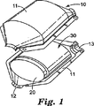
図1を参照すると、汚染制御装置10は、一般に円錐台形の入口及び出口末端部、それぞれ12及び13を有する金属ケーシング11を備える。ケーシング11内に配置されているのは、汚染制御モノリス20である。本発明の特定の実施形態に従えば、汚染制御モノリス20は、例えば、複数のそこを抜けるガス流路(示されていない)を有するハニカム構造の一体型ボディから形成されたディーゼル汚染制御モノリスである。汚染制御モノリス20は、ガソリンエンジンからの排気ガスの処理に採用されるものであってもよい。それにもかかわらず、本発明の実装マットは、特にディーゼル汚染制御モノリスと共に使うのに適しており、従って本発明はディーゼルエンジン排気ガスの処理に関連してさらに記述されるが、本発明を限定する意図は無い。ディーゼル汚染制御モノリス20の周囲は、長無機繊維及び短無機繊維、例えば長く及び短く細断された、ないしは別の方法で分割された(例えば、繊維又はマット処理の次工程で繊維を破断することによって)ケイ酸アルミニウムガラス繊維の層を含む実装マット30であり、ケーシング11内に一体型要素20をしっかりとしかし弾力的に支持する役目をはたす。実装マット30は、ディーゼル汚染制御モノリス20をケーシングの中で定位置に保持し、ディーゼル排気ガスがディーゼル汚染制御モノリス20を迂回するのを防止し又は最小にするために、ディーゼル汚染制御モノリス20とケーシング11の間の隙間を密封する。
Referring to FIG. 1, the
金属ケーシングは、ステンレススチールを含むそのような用途に対し当該技術分野において既知の材料から作ることができる。 The metal casing can be made from materials known in the art for such applications including stainless steel.
汚染制御装置10に使うディーゼル汚染制御モノリスの実施例は、触媒コンバータ及びディーゼル微粒子フィルター又はトラップを含む。触媒コンバータは、典型的に金属ハウジング内に実装された一体型構造物にコーティングされた触媒を含む。触媒は、作用し、効果的であり、低温であり、350℃以下であるように、適合させられる。一体型構造物は、典型的にセラミックであるが、金属モノリスも使われてきた。触媒は、大気汚染を制御するために、排気ガス中の一酸化炭素及び炭化水素を酸化させ、窒素酸化物を還元する。ガソリンエンジンでは3つのこれら汚染物質全てが、いわゆる「三元コンバータ」内で同時に反応しうるが、殆どのディーゼルエンジンは、ディーゼル酸化触媒コンバータのみを装備している。今日ディーゼルエンジンに対して限られた使い方しかされていない窒素酸化物を減らすための触媒コンバータは、一般に別々の触媒コンバータからなる。触媒担体として使われる好適なセラミックモノリスは、コーニング有限会社(Corning Inc.)(ニューヨーク州コーニング(Corning N.Y))の商標名である「セルカー(CELCOR)」から市販、またNGK絶縁有限会社(NGK Insulated Ltd)(日本、名古屋)の商標名である「ハニーセラム(HONEYCERAM)」から市販。
Examples of diesel pollution control monoliths for use in
ディーゼル微粒子フィルター又はトラップは、典型的に、多孔質の結晶性セラミック材料から作られるハニカム状の一体型構造体を有する、典型的に壁状フローフィルターである。ハニカム構造の代替セルは典型的に、1つのセルに入った排気ガスが多孔質の壁を通って、構造体から出ることができる隣接したセルに強制的に抜けるように詰められている。このようにして、ディーゼル排気ガス中に存在する小さな煤煙粒子が集められる。コージライトから作られる好適なディーゼル微粒子フィルターは、コーニング有限会社(Corning Inc.)(ニューヨーク州コーニング( Corning N.Y.))から、またNGK絶縁有限会社(NGK Insulated Inc.)(日本、名古屋)から商業的に得られる。シリコンカーバイドから作られたディーゼル微粒子フィルターは、イビデン株式会社(Ibiden Co. Ltd.)(日本)から商業的に得られ、また例えば日本公開特許第2002047070A号に記載されている。 Diesel particulate filters or traps are typically wall flow filters that typically have a honeycomb-like unitary structure made from a porous crystalline ceramic material. Alternative cells of a honeycomb structure are typically packed so that exhaust gas entering one cell is forced through a porous wall into an adjacent cell that can exit the structure. In this way, small soot particles present in the diesel exhaust gas are collected. Suitable diesel particulate filters made from cordierite are commercially available from Corning Inc. (Corning NY, NY) and from NGK Insulated Inc. (Nagoya, Japan). Is obtained. Diesel particulate filters made from silicon carbide are obtained commercially from Ibiden Co. Ltd. (Japan) and are described, for example, in Japanese Patent Publication No. 2002047070A.
長繊維及び短繊維の混合物の繊維は、好ましくは非呼吸性である。繊維は、典型的に少なくとも5μmの平均直径を有する。好ましくは、平均直径は少なくとも7μmであり、また典型的には7μm〜14μmの範囲である。一般に長繊維及び短繊維の混合物は、連続的に形成されたセラミック繊維、例えばガラス繊維の混合物である。典型的に短繊維は、13mm以下、例えば10mm又は8mm以下の長さを有する。長繊維は、典型的に少なくとも20mm、例えば少なくとも25mm又は特定の実施形態では少なくとも30mmの長さを有する。長繊維の最大長さは特に重大ではないが、便宜的には最大約15cmである。短繊維の量は、典型的に長繊維及び短繊維の混合物の総重量に対して少なくとも3重量%、例えば、少なくとも5重量%又は特殊な実施形態では少なくとも6重量%である。典型的に長繊維及び短繊維の混合物は、層における繊維の少なくとも50重量%、例えば、層における繊維の総重量の少なくとも80重量%及び典型的には多分90重量%又は約100重量%を構成する。一般に短繊維が、繊維層全体に均質に分散していることが望ましい。この文脈で「均質」は、層中に短繊維が濃縮された区域が無いか又は小さくあるだけであると理解されるべきである。換言すれば、第一層はかなり均一にみえるはずである。それにもかかわらず、層内での短繊維の不均一又は不均質な分散は同じように使うことができるが、そのとき前述の利点を得るために一般には多量の短繊維を使うことが必要になる。 The fibers of the mixture of long and short fibers are preferably non-breathing. The fibers typically have an average diameter of at least 5 μm. Preferably, the average diameter is at least 7 μm and typically ranges from 7 μm to 14 μm. In general, the mixture of long and short fibers is a mixture of continuously formed ceramic fibers, such as glass fibers. Typically, short fibers have a length of 13 mm or less, such as 10 mm or 8 mm or less. Long fibers typically have a length of at least 20 mm, such as at least 25 mm or in certain embodiments at least 30 mm. The maximum length of the long fiber is not particularly critical, but for convenience it is up to about 15 cm. The amount of short fibers is typically at least 3% by weight, for example at least 5% by weight or in special embodiments at least 6% by weight, based on the total weight of the mixture of long and short fibers. Typically, the mixture of long and short fibers comprises at least 50% by weight of the fibers in the layer, for example at least 80% by weight and typically 90% or about 100% by weight of the total weight of fibers in the layer. To do. In general, it is desirable that the short fibers are uniformly dispersed throughout the fiber layer. “Homogeneous” in this context should be understood as having no or small areas where the short fibers are concentrated in the layer. In other words, the first layer should appear fairly uniform. Nevertheless, a non-uniform or heterogeneous dispersion of short fibers within the layer can be used in the same way, but then it is generally necessary to use a large amount of short fibers in order to obtain the aforementioned advantages. Become.
短繊維及び長繊維の混合物を包含する層は、13mm及び20mmの間の長さを有する繊維を含む他の繊維を含んでもよい。特殊な実施形態において、短繊維及び長繊維の混合物は、ガラス繊維の混合物、特にケイ酸マグネシウム・アルミニウムガラス繊維である。特殊な実施形態では、実装マットの繊維層は、実装マットの層における繊維の総重量の少なくとも50重量%を構成する長ケイ酸マグネシウム・アルミニウムガラス繊維及び短ケイ酸マグネシウム・アルミニウムガラス繊維の混合物を含む。特殊な実施形態では、混合物の量は、少なくとも60%又は少なくとも80%であり、典型的な実施形態では繊維層のほぼ全て(90%〜100%)が長ケイ酸アルミニウムガラス繊維及び短ケイ酸アルミニウムガラス繊維の混合物によって構成されている。 The layer containing a mixture of short fibers and long fibers may include other fibers including fibers having a length between 13 mm and 20 mm. In a special embodiment, the mixture of short fibers and long fibers is a mixture of glass fibers, in particular magnesium silicate aluminum glass fibers. In a special embodiment, the fiber layer of the mounting mat comprises a mixture of long magnesium silicate / aluminum glass fibers and short magnesium silicate / aluminum glass fibers comprising at least 50% by weight of the total weight of fibers in the layers of the mounting mat. Including. In a special embodiment, the amount of the mixture is at least 60% or at least 80%, and in a typical embodiment almost all of the fiber layers (90% -100%) are long aluminum silicate glass fibers and short silicates It is composed of a mixture of aluminum glass fibers.
繊維が、好ましくは個別化される。個別化された(即ち、各繊維を互いに分離する)繊維を供給するために、繊維のトウ又は糸が、例えば、ガラスロービングカッター(例えば、カリフォルニア州パコマ(Pacoma, Calif.)のフィンアンドフラム有限会社(Finn & Fram, Inc.)の商標名である「モデル90ガラスロービングカッター(MODEL 90 GLASS ROVING CUTTER)」で商業的に得られる)を使って所望の長さに細断され得る。繊維は典型的に、塊りを含まないか又は非常に低い量、典型的には繊維の総重量に対して1重量%未満の、塊りを含む。加えて、繊維は、典型的に適度に均一な直径であり、即ち、平均値の+/−3μm以内の直径を有する繊維の量は、一般に繊維の総重量の少なくとも70重量%、好ましくは少なくとも80重量%及び最も好ましくは少なくとも90重量%である。 The fibers are preferably individualized. To supply individualized fibers (ie, separate each fiber from each other), fiber tows or yarns are, for example, glass and roving cutters (eg, Fin and Fram Co., Pacoma, Calif.). It can be shredded to the desired length using a trade name “MODEL 90 GLASS ROVING CUTTER” which is a trade name of the company (Finn & Fram, Inc.). The fibers typically contain no lumps or very low amounts, typically less than 1% by weight, based on the total weight of the fiber. In addition, the fibers are typically of a reasonably uniform diameter, i.e. the amount of fibers having a diameter within +/- 3 [mu] m of the mean value is generally at least 70% by weight of the total weight of the fibers, preferably at least 80% by weight and most preferably at least 90% by weight.
マットは、異なる繊維の混合物、例えばケイ酸マグネシウム・アルミニウムガラス繊維と、例えばアルミニウムシリカ繊維又は多結晶性繊維のような他の繊維との混合物を含んでもよい。しかし好ましくは、マットは、実質的に全て又は殆どケイ酸マグネシウム・アルミニウムガラス繊維しか含まない。もし他の繊維がマットに含まれるならば、それらは短繊維及び長繊維混合物の層に含まれてよいか、或いはそれらは実装マットの別々の層又は部分に存在し得る。一般に、ケイ酸マグネシウム・アルミニウムガラス繊維以外のさらなる繊維は、非晶質繊維であり、またそれらは好ましくは少なくとも5μmの平均直径も有するべきである。好ましくは、マットは、直径3μm以下の繊維を含むか実質的に含まず、より好ましくはマットは直径5μm未満の繊維を含むか実質的に含まない。本明細書で本質的に含まないとは、そのような小さな直径の繊維の量がマットにおける繊維の総重量の2重量%以下、好ましくは1重量%以下であることを意味する。 The mat may comprise a mixture of different fibers, such as magnesium silicate aluminum glass fibers, and other fibers, such as aluminum silica fibers or polycrystalline fibers. Preferably, however, the mat contains substantially all or almost only magnesium silicate aluminum fiberglass. If other fibers are included in the mat, they may be included in layers of short fibers and long fiber mixtures, or they may be present in separate layers or portions of the mounting mat. In general, further fibers other than magnesium silicate aluminum glass fibers are amorphous fibers and they should preferably also have an average diameter of at least 5 μm. Preferably, the mat includes or is substantially free of fibers having a diameter of 3 μm or less, more preferably the mat includes or is substantially free of fibers having a diameter of less than 5 μm. Essentially free herein means that the amount of such small diameter fibers is not more than 2%, preferably not more than 1% by weight of the total weight of fibers in the mat.
本発明において使用しうるケイ酸マグネシウム・アルミニウムガラス繊維の例は、10重量%及び30重量%の間の酸化アルミニウム、52重量%及び70重量%の間の酸化ケイ素、並びに1%及び12%の間の酸化マグネシウムを有するガラス繊維を含む。前述の酸化物の重量パーセントは、Al2O3、SiO2、及びMgOの理論的な量に基づいている。ケイ酸マグネシウム・アルミニウムガラス繊維が、追加の酸化物を含んでよいことはさらに理解される。例えば、存在してもよい追加の酸化物は、酸化ナトリウム又は酸化カリウム、酸化ホウ素及び酸化カルシウムを含む。マグネジウムアルミニウムケイ酸塩ガラス繊維の特殊な例は、典型的に約55%のSiO2、約11%のAl2O3、約6%のB2O3、約18%のCaO、約5%のMgO及び約5%の他の酸化物の組成物を有するE−ガラス繊維、典型的に約65%のSiO2、約25%のAl2O3及び約10%のMgOの組成物を有するS及びS−2ガラス繊維、並びに典型的に60%のSiO2、25%のAl2O3、9%のCaO及び6%のMgOの組成物を有するR−ガラス繊維を含む。E−ガラス、S−ガラス及びS−2ガラスは、例えばアドバンストグラスファイバーヤーン有限責任会社(Advanced Glassfiber Yarns LLC)から得られ、またR−ガラスは、セントゴバインヴィトロテックス(Saint-Gobain Vetrotex)から得られる。 Examples of magnesium silicate aluminum glass fibers that can be used in the present invention include between 10% and 30% by weight aluminum oxide, between 52% and 70% by weight silicon oxide, and 1% and 12%. Includes glass fiber with magnesium oxide in between. The weight percentages of the aforementioned oxides are based on the theoretical amounts of Al 2 O 3 , SiO 2 , and MgO. It is further understood that the magnesium silicate aluminum glass fibers may include additional oxides. For example, additional oxides that may be present include sodium or potassium oxide, boron oxide and calcium oxide. Special examples of magnedium aluminum silicate glass fibers are typically about 55% SiO 2 , about 11% Al 2 O 3 , about 6% B 2 O 3 , about 18% CaO, about 5 % of MgO and about 5% of the E- glass fiber having a composition of other oxides, typically about 65% SiO 2, the composition of about 25% of Al 2 O 3 and about 10% MgO S and S-2 glass fibers having, and typically containing 60% of SiO 2, 25% of the Al 2 O 3, 9% of the CaO and 6% of the R- glass fibers having an MgO composition. E-glass, S-glass and S-2 glass are obtained, for example, from Advanced Glassfiber Yarns LLC, and R-glass is from Saint-Gobain Vetrotex. can get.
実装マットを作る特殊な方法において、繊維は切られ又は細断され、それからそれらを従来の2ゾーンラロシュオープナー(two zone Laroche Opener)(例えば、フランス、ラクール市のラロシュS.A.社(Laroche S.A., Cours la Ville, France)から商業的に得られる)を通すことによって分けることができる。繊維は、またそれらをハンマーミル、好ましくは送風排出ハンマーミル(blow discharge hammer mill)(例えば、オハイオ州チフィンのC.S.ベル社の商標名である「ブロアーディスチャージモデル20ハンマーミル」から市販(commercially available under the trade designation “BLOWER DISCHARGE MODEL 20 HAMMER MILL” from C.S. Bell Co. of Tiffin, Ohio))を通して分けることもできる。効果は少ないが、イリノイ州シカゴのW.W.グレンジャー(W. W. Grainger of Chicago, Ill.)から市販の商標名である「ダイトンラジアルブロアー(DAYTON RADIAL BLOWER)」モデル3C539、31.1cm(12.25インチ、3馬力、のような従来のブロアーを使って繊維は個々に分けることができる。細断された繊維は、通常、ラロシュオープナーを一度だけ通す必要がある。ハンマーミルを使うときは、それらは一般に二度通されなければならない。ブロアーが単独で使われると、繊維は典型的にそれに少なくとも二回通される。好ましくは、繊維の少なくとも50重量%が、実装マットの層に形成される前に別々に分けられる。そのような分離処理工程が、所望よりも長い繊維を所望の長さに、さらに分割又は破断するために使われうることが見出されてきた。
In a special way of making mounting mats, the fibers are cut or chopped, and then they are converted into a conventional two zone Laroche Opener (eg Laroche SA, Lacourt, France). , Cours la Ville, France)). The fibers are also commercially available from a hammer mill, preferably a blow discharge hammer mill (eg, “
実装マットを作成する方法によると、裁断され、別々に分けられた繊維は、従来のウェブ成形機(例えば、ニューヨーク州マチェドン(Macedon, N.Y.)のランドマシン社(Rando Machine Corp.)の商標名である「ランドウエバー(RANDO WEBBER)」、又はデンマークのスキャンウェブ社(ScanWeb Co.)からの「ダンウェブ(DAN WEB)」から市販)に供給され、繊維は、ワイヤスクリーン又はメッシュベルト(例えば、金属又はナイロンベルト)の上に引き出される。もし「ダンウェブ」−タイプウェブ−成形機が使われるならば、繊維は、好ましくはハンマーミルを使って次いでブロアーで個別化される。約2.5cmを超える長さを有する繊維は、ウェブ形成工程で混線する傾向がある。マットの処理を容易にするために、マットはスクリムの上で形成されてもよく、又は上に置かれ得る。繊維の長さに依存して、結果として得られるマットは典型的に、ニードルパンチ機に支持体(例えば、スクリム)を必要としないで移送される十分な取り扱い性を有する。 According to the method of making the mounting mat, the cut and separately separated fibers are known under the trade name of a conventional web forming machine (eg, Rando Machine Corp., Macedon, NY). Supplied to certain “RANDO WEBBER” or “DAN WEB” from ScanWeb Co., Denmark, and the fibers can be wire screens or mesh belts (eg metal or Nylon belt). If a "dan web" -type web-forming machine is used, the fibers are preferably individualized with a blower and then with a blower. Fibers having a length greater than about 2.5 cm tend to cross-link during the web forming process. To facilitate the processing of the mat, the mat may be formed on or placed on the scrim. Depending on the length of the fiber, the resulting mat typically has sufficient handleability to be transferred without the need for a support (eg, scrim) to the needle punch machine.
短繊維及び長繊維の工夫に富む混合物は、所望の短繊維及び長繊維の混合物をウェブ形成機に供給することによって実現されてもよい。或いは、所望よりも長い繊維だけが、ウェブ形成機に供給されることが可能であり、個別化及び/又はウェブ形成の条件は、通常の場合のように繊維の切断を避ける条件を設定するよりはむしろある程度の量の繊維を慎重に切断させるように、設定される。その場で繊維を分割又は切断する方法は、特に繊維層で繊維の均一分散を生じるのに適している。しかし、所望の混合物をウェブ形成プロセスに供給することも可能である。また、所望の短繊維及び長繊維の混合物の供給及び所望よりも長いある程度の量の繊維を切断させる条件との組合せも実行できる。 A rich mixture of short and long fibers may be achieved by feeding the desired mixture of short and long fibers to a web forming machine. Alternatively, only fibers that are longer than desired can be fed into the web forming machine, and the conditions for individualization and / or web formation are more than setting conditions to avoid fiber cutting as is usual. Rather, it is set to carefully cut a certain amount of fiber. The method of splitting or cutting the fibers in situ is particularly suitable for producing a uniform dispersion of the fibers in the fiber layer. However, it is also possible to feed the desired mixture to the web forming process. Also, a combination of supplying the desired mixture of short fibers and long fibers and conditions for cutting a certain amount of fibers longer than desired can be performed.
実装マットの作成において繊維の切断又は他の分割は、個々の繊維に応力を加えること、例えば繊維ストランド(束)を間隙を通し、テーカインロールが高速回転している間に間隙内で繊維をクランプして供給し、又は繊維の切断を起こすピン又は歯を持つテーカインロールを使うこと、によって引き起こされてもよい。繊維の切断は、開口部或いはウェブ形成段階のどちらか又は両方で起きてもよい。 In the creation of the mounting mat, the cutting or other splitting of the fibers applies stress to the individual fibers, for example, passing the fiber strands (bundles) through the gaps and pulling the fibers within the gaps while the take-in roll is rotating at high speed. It may be caused by clamping and feeding or by using a take-in roll with pins or teeth that cause fiber cutting. Fiber cutting may occur at either or both the opening and web forming stages.
特殊な実施形態においては、実装マットは、ニードルパンチされた不織布マットである。ニードルパンチされた不織布マットとは、例えばかかりのついた針による、複数の全体的又は部分的(好ましくは、全体的)なマットの貫通によってもたらされる繊維の物理的なもつれがあるマットのことを言う。不織布マットは、従来のニードルパンチ装置(例えば、ドイツのディロ(Dilo of Germany)の商標名である「ディロ(DIRO)」の市販のニードルパンチャーで、かかりのついた針(例えばウイスコンシン州マニトウォク(Manitowoc, Wis.)のフォスターニードルカンパニー社(Foster Needle Company, Inc.,)から市販)を備えた)を使って、ニードルパンチされた不織布マットを提供するために、ニードルパンチすることができる。繊維のもつれを与えるニードルパンチングは、典型的にマットを圧縮し、それからかかりのついた針をマットを貫いて押込んで引き出すことを含む。マットの面積当たりのニードルパンチの最適な数は、特定の用途によって変わる。典型的には、不織布マットは、約5/cm2〜約60/cm2のニードルパンチを供給するようにニードルパンチされる。好ましくは、マットは、約10/cm2〜約20/cm2のニードルパンチを供給するようにニードルパンチされる。 In a special embodiment, the mounting mat is a needle punched nonwoven mat. A needle-punched non-woven mat is a mat with physical entanglement of fibers brought about by the penetration of a plurality of total or partial (preferably total) mats, for example by barbed needles. To tell. Nonwoven mats are conventional needle punchers such as the commercial needle puncher under the trade name “DIRO” under the trade name Dilo of Germany, for example, with a barbed needle (eg Manitowoc, Wis.). , Wis.) (Commercially available from Foster Needle Company, Inc.)) can be needle punched to provide a needle punched nonwoven mat. Needle punching to provide fiber entanglement typically involves compressing the mat and then pushing the barbed needle through the mat and pulling it out. The optimum number of needle punches per mat area will vary depending on the particular application. Typically, the nonwoven mat is needle punched to provide a needle punch of about 5 / cm 2 to about 60 / cm 2 . Preferably, the mat is needle punched to provide a needle punch of about 10 / cm 2 to about 20 / cm 2 .
好ましくは、ニードルパンチされた不織布マットは、約1000g/m2〜約3000g/m2の範囲にある単位面積当たりの重量値、また別の態様では約0.5センチメートル〜約3センチメートルの範囲の厚さを有する。5kPaの荷重下での典型的な嵩密度は、0.1g/cc〜0.2g/ccの範囲である。 Preferably, the needle punched nonwoven mat has a weight value per unit area in the range of about 1000 g / m 2 to about 3000 g / m 2 , and in another embodiment about 0.5 centimeters to about 3 centimeters. Have a thickness in the range. Typical bulk density under a load of 5 kPa is in the range of 0.1 g / cc to 0.2 g / cc.
不織布マットは、従来のテクニック(例えば、米国特許番号第4,181,514(レフコヴィッツ(Lefkowitz)ら)を参照、その開示は本明細書にスティッチボンディング不織布マットの教示のために参照として盛り込まれている)を使ってスティッチボンドすることができる。典型的に、マットは、有機系の糸でスティッチボンドされる。有機又は無機のシート材料の薄い層が、スティッチボンディングの間、糸がマットを通して切断することを防ぎ又は最小にするために、マットのどちらか一方又は両方のサイド上に置かれ得る。使用する際にスティッチング糸が分解しないことが望まれるところでは、セラミック又は金属(例えば、ステンレススチール)のような無機繊維を使うことができる。スティッチの間隔は、繊維がマットの全領域で均一に圧縮されるように、通常3mm〜30mmである。本発明の特定の実施形態にしたがって、マットはケイ酸マグネシウム・アルミニウムガラス繊維の複数の層、そのうちの少なくとも1つは短繊維及び長繊維の混合物を有する、を含んでよい。そのような繊維は、使われる繊維の平均直径、使われる繊維の長さ、及び/又は使われる繊維の化学的組成で、互いに区別されてよい。温度での繊維の熱抵抗性及び機械的強度は、組成及び程度は少ないが繊維直径で変わる故に、コストを最小にして性能を最適にするように繊維層を選ぶことができる。例えば、E−ガラスの層と組み合わせたS−2ガラスの層層からなる不織布マットは、ディーゼル触媒コンバータを実装することができる。使用中、S−2ガラス層は、より熱い触媒コンバータのモノリス側に対して直接配置され、一方E−ガラス層は、より冷たい触媒コンバータの金属ハウジング側に対している。層状混合マットは、S−2ガラス繊維のみからなるマットに比べて大幅に減らしたコストで、E−ガラス繊維のみからなるマットよりかなり高温に耐えることができる。層状マットは、最初に特定のタイプの繊維を有する個々の不織布マットを先に述べた成形技術を使って形成することによって、製造する。これらの層は、次に所望の別個の層を有する完成したマットを形成するために一緒にニードルボンドされる。 Nonwoven mats refer to conventional techniques (eg, US Pat. No. 4,181,514 (Lefkowitz et al.), The disclosure of which is incorporated herein by reference for the teaching of stitchbonded nonwoven mats. Can be stitch-bonded. Typically, the mat is stitchbonded with organic yarns. A thin layer of organic or inorganic sheet material can be placed on either or both sides of the mat to prevent or minimize yarn cutting through the mat during stitch bonding. Where it is desired that the stitching yarn not break down in use, inorganic fibers such as ceramic or metal (eg, stainless steel) can be used. The stitch spacing is typically 3-30 mm so that the fibers are uniformly compressed over the entire area of the mat. In accordance with certain embodiments of the present invention, the mat may include a plurality of layers of magnesium silicate aluminum glass fibers, at least one of which has a mixture of short and long fibers. Such fibers may be distinguished from each other by the average diameter of the fibers used, the length of the fibers used, and / or the chemical composition of the fibers used. Since the thermal resistance and mechanical strength of the fiber at temperature is less in composition and degree but varies with fiber diameter, the fiber layer can be chosen to minimize cost and optimize performance. For example, a nonwoven mat comprising a layer layer of S-2 glass combined with a layer of E-glass can be mounted with a diesel catalytic converter. In use, the S-2 glass layer is placed directly against the monolith side of the hotter catalytic converter, while the E-glass layer is against the metal housing side of the cooler catalytic converter. The layered mixed mat can withstand considerably higher temperatures than a mat consisting of only E-glass fibers at a cost significantly reduced compared to a mat consisting of only S-2 glass fibers. Layered mats are manufactured by first forming individual nonwoven mats having specific types of fibers using the molding techniques described above. These layers are then needle bonded together to form a finished mat with the desired separate layers.
本発明の実装マットは、特にディーゼル汚染制御モノリスを汚染制御装置に実装するのに適している。典型的に、マットの実装密度、即ち組み立て後のマットの嵩密度は、モノリスを定位置に安全に保持するよう十分な圧力を与えるために、少なくとも0.2g/cm3にすべきである。約0.70g/cm3より上の実装密度で繊維は、ひどく破砕され得る。非常に高い実装密度でも、モノリスが汚染制御装置の組み立て中に壊れる危険がある可能性がある。好ましくは、実装密度は、約0.25g/cm3〜約0.45g/cm3の間にあるべきである。汚染制御装置は、ディーゼルエンジン排気ガスの処理におけるような低温用途の使用に対して優れた性能特性を有する。汚染制御装置は、そこに備えられているディーゼルエンジンから出る排気ガスを処理するために、固定機械に使われてもよい。そのような固定機械は、例えば電気又はポンプ流体を発生させる電源を含む。 The mounting mat of the present invention is particularly suitable for mounting a diesel pollution control monolith on a pollution control device. Typically, the mat packing density, ie the bulk density of the mat after assembly, should be at least 0.2 g / cm 3 to provide sufficient pressure to safely hold the monolith in place. Fibers can be severely crushed at packaging densities above about 0.70 g / cm 3 . Even at very high packaging densities, there is a risk that the monolith will break during assembly of the pollution control device. Preferably, packing density should be between about 0.25 g / cm 3 ~ about 0.45 g / cm 3. The pollution control device has excellent performance characteristics for use in low temperature applications such as in diesel engine exhaust gas treatment. The pollution control device may be used in a stationary machine to treat the exhaust gas emitted from the diesel engine provided therein. Such stationary machines include, for example, a power source that generates electricity or pump fluid.
汚染制御装置は、特にモータービヒクルのディーゼルエンジンからの排気ガスの処理に適している。そのようなモータービヒクルの例は、汽車、バス、トラック及び「低定員」乗用車を含む。「低定員」乗用車は少人数、典型的には15人以下、の乗客を運ぶために設計された自動車を意味する。それらの例は、乗用車、バン及びいわゆる一人乗り(mono-volume)自動車を含む。汚染制御装置は、特にヨーロッパでモータービヒクルに非常に頻繁に使われているターボチャージャー付直接噴射式ディーゼルエンジン(TDI)からの排気ガスの処理に、特に適している。 The pollution control device is particularly suitable for the treatment of exhaust gas from a motor vehicle diesel engine. Examples of such motor vehicles include trains, buses, trucks and “low-capacity” passenger cars. “Low-capacity” passenger car refers to an automobile designed to carry a small number of passengers, typically no more than 15 passengers. Examples include passenger cars, vans and so-called mono-volume cars. Pollution control devices are particularly suitable for the treatment of exhaust gases from turbocharged direct injection diesel engines (TDI), which are very frequently used in motor vehicles in Europe.
以下の実施例は本発明を更に、しかし本発明の範囲をそれに加えて制限する意図無しに、説明する。 The following examples illustrate the invention further, but without intending to limit the scope of the invention in addition thereto.
実施例で用いられる材料
平均直径約10μm及び長さ36mmのR−ガラス繊維(RC−10P109)(フランス、チャンベリセデクスのセントゴバインヴィトロテックスフランス社(Saint-Gobain Vetrotex France SA, Chambery Cedex, France)から得られる)が使われる。
Materials used in the examples R-glass fibers (RC-10P109) with an average diameter of about 10 μm and a length of 36 mm (Saint-Gobain Vetrotex France SA, Chambery Cedex, France ) Obtained from) is used.
試験方法
繊維長の測定
繊維長の測定は、12.7mm未満の長さを有する繊維の量を決めるために、実施例で準備されたマットからの試料について実施される。
Test Method Fiber Length Measurement Fiber length measurement is performed on samples from the mats prepared in the Examples to determine the amount of fiber having a length of less than 12.7 mm.
試験装置は、試料の重さを検知するためのはかり、繊維束が単繊維測定のために分離される領域、及び単繊維が光センサーを通過して空気で輸送される領域を備えている。使用された特殊な装置は、モデル「アドバンストファイバーインフォメーションシステム(Advanced Fiber Information System)」(AFIS)(スイス、ウスター、ウスターテクノロジー株式会社(USTER Technologies AG, Uster, Switzerland))として市販されている測定装置である。機器は、繊維長測定のために「L−モジュール」モードで使われる。機械は、既知の長さのポリエステル繊維を使って較正される。 The test apparatus includes a scale for detecting the weight of the sample, a region where the fiber bundle is separated for single fiber measurement, and a region where the single fiber is transported by air through the optical sensor. The special device used is a measuring device marketed as model "Advanced Fiber Information System" (AFIS) (USTER Technologies AG, Uster, Switzerland). It is. The instrument is used in “L-module” mode for fiber length measurement. The machine is calibrated using polyester fibers of known length.
各々約0.5gを秤量された繊維10試料が、試験されるためにマットから取り出される。各試料は、次にAFISテスターで秤量される。試料は、次に繊維が輸送方向に平行になるよう繊維束が向いていることを確かめながら、手で輸送バンドに置かれる。 Ten fiber samples, each weighing about 0.5 g, are removed from the mat to be tested. Each sample is then weighed with an AFIS tester. The sample is then placed by hand in the transport band, making sure that the fiber bundle is oriented so that the fibers are parallel to the transport direction.
繊維が、逆回転しているカーディングロールが繊維束が単繊維に分けられた細い針を有する分離領域に、自動的に搬送される。繊維は、次にさらに、決められた速度で空気流によって、光学的赤外線センサーを通過して空気輸送される。このセンサーは、単繊維の数及びそれらの長さを検知する。測定は、3000繊維を検知した後に終了する。 The fibers are automatically transported to the separation area where the carding roll, which is rotating in the reverse direction, has a fine needle in which the fiber bundle is divided into single fibers. The fibers are then further pneumatically transported through the optical infrared sensor by air flow at a determined speed. This sensor detects the number of single fibers and their length. The measurement ends after detecting 3000 fibers.
テスト結果は、繊維の頻度(%)対繊維長(mm)、を示すグラフとして表示される。グラフから、12.7mm未満の長さを有する繊維のパーセンテージが、AFISシステムに内蔵されたソフトウエアを使って導かれる。10測定が、平均され報告される。報告されたパーセンテージは、W、重量に対しての繊維の中央値の長さ、に基づく。 The test results are displayed as a graph showing fiber frequency (%) versus fiber length (mm). From the graph, the percentage of fibers having a length of less than 12.7 mm is derived using software built into the AFIS system. Ten measurements are averaged and reported. The reported percentage is based on W, the median length of fiber relative to weight.
静的圧縮試験
静的圧縮試験は、圧縮に対する抵抗性を決めるために実施例で準備されたマットについての周囲条件で実施される。試験装置は、互いに向かって進むことができる2つのアンビルを、それらの間に置かれたマット試料を圧迫するように、備える。使われた特殊な装置は、材料試験システム(Material Test System)モデルRT/30(米国、ミネソタ州エデンプレイリー、MTSアライアンス(商標)(MTS Allience, Eden Prairie MN, USA)から得られる)である。装置は、マット試料の圧縮に対する抵抗性を測定するために5kNのロードセルと、及び圧縮の様々なステージでの試料の厚さを測定する高さ測定装置とが取り付けられる。
Static compression test The static compression test is performed at ambient conditions on the mats prepared in the examples to determine resistance to compression. The test device is equipped with two anvils that can be advanced towards each other so as to compress a mat sample placed between them. The special equipment used is the Material Test System Model RT / 30 (obtained from MTS Alliance ™, Eden Prairie, Minnesota, USA). . The apparatus is fitted with a 5 kN load cell to measure the resistance of the mat sample to compression and a height measurement device that measures the thickness of the sample at various stages of compression.
試料は、完成した実装マットから50.8mmの直径の円形に型抜きすることで準備される。3試料が、端から少なくとも25mmでマットの幅を横切って等間隔で取り出される。試料間の距離は、少なくとも100mmである。各試料は、面積当たりの重量約1300g/m2(+/−15%)を有した。試験は、以下の手順で実施される。各試料は、最初に秤量される。次に、各試料の面積当たりの重量は、試料の重量を試料の表面積(既知の直径50.8mmから計算する)で割ることによって計算され、g/mm2で記録される。 The sample is prepared by die-cutting from a completed mounting mat into a circle with a diameter of 50.8 mm. Three samples are taken at equal intervals across the width of the mat at least 25 mm from the edge. The distance between the samples is at least 100 mm. Each sample had a weight per area of about 1300 g / m 2 (+/− 15%). The test is performed according to the following procedure. Each sample is first weighed. The weight per area of each sample is then calculated by dividing the weight of the sample by the surface area of the sample (calculated from a known diameter of 50.8 mm) and recorded in g / mm 2 .
最終的な圧縮された密度0.40g/cm3に達するために必要なアンビル間の間隙が次に計算される。これは圧縮に対する抵抗を測るには所望の密度である。 The gap between the anvils required to reach the final compressed density of 0.40 g / cm 3 is then calculated. This is the desired density to measure resistance to compression.
計算例: Calculation example:

このように、1300g/m2の面積当たりの重量及び初期密度約0.15g/cm3をもつ試料は、最終的な密度0.4g/cm3を得るために厚さ0.325cm(3.25mm)に圧縮される必要がある。試料は、次に試験装置の下のアンビルに置かれる。アンビル間の間隙は、次にアンビル間の距離20mmから始まって、1分当たり25.4mmの速度で閉じられる。アンビルの前進は、次いで上で計算されたアンビル間の間隙で止められる。 Thus, 1300 g / m samples with weight and an initial density of about 0.15 g / cm 3 per unit area of 2, the final density of 0.4 g / cm 3 in order to obtain a thickness of 0.325cm (3. 25 mm). The sample is then placed on the anvil under the test apparatus. The gap between the anvils is then closed at a rate of 25.4 mm per minute, starting with a distance of 20 mm between the anvils. Anvil advance is then stopped at the gap between the anvils calculated above.
計算された間隙距離での45秒間の圧縮の後、圧縮に対する抵抗性が測定されkPaで記録される。 After 45 seconds of compression with the calculated gap distance, the resistance to compression is measured and recorded in kPa.
(実施例1)
平均直径約10μm及び長さ36mmのR−ガラスP109繊維は、フランス、チャンベリセデクス、セントゴバインヴィトロテックスフランス社(Saint-Gobain Vetrotex France SA, Chambery Cedex, France)から得られる。繊維は、実質的に塊りの無いものである。
Example 1
R-glass P109 fibers having an average diameter of about 10 μm and a length of 36 mm are obtained from Saint-Gobain Vetrotex France SA, Chambery Cedex, France. The fiber is substantially free of lumps.
40kgの量のガラス繊維が、ピンを備えたテーカインロールを有するラロッシュオープナーに広げられる。ストランドは、第二領域に搬送速度3m/min及び2,000rpmのテーカインロール速度で直接供給される。排出速度は、6.0m/minである。広げられた繊維は、次いで従来のウェブ形成機ランドウエバー(Rando webber)に供給され、繊維は連続ウェブを形成するために多孔質の金属ロール上に吹き出される。テーカインロールは、歯を有し、テーカインの速度は1900rpm、持ち上がり装置の速度は300rpm、ストリッパーの速度は350rpmである。フィードロールの速度は1.1rpmであり、フィーダーの押下は51.7kPa(7.5psi)であり、ウエバーの押下は48kPa(7psi)である。蓋の開口は、30mmである。ライン速度は、1m/minである。 A 40 kg quantity of glass fiber is spread on a Laroche opener with a take-in roll with pins. The strands are fed directly to the second area at a transport speed of 3 m / min and a take-in roll speed of 2,000 rpm. The discharge speed is 6.0 m / min. The spread fibers are then fed to a conventional web forming machine Rando webber, where the fibers are blown onto a porous metal roll to form a continuous web. The take-in roll has teeth, the take-in speed is 1900 rpm, the lifting device speed is 300 rpm, and the stripper speed is 350 rpm. The feed roll speed is 1.1 rpm, the feeder press is 51.7 kPa (7.5 psi), and the weber press is 48 kPa (7 psi). The opening of the lid is 30 mm. The line speed is 1 m / min.
連続ウェブは、次いで従来のニードル打ち込み機でニードルボンドされた。ニードルタイプGB15×16×31/2R222G53047(ドイツ、グロズベッケルトグループ(Groz-Beckert Group, Germany))。ニードル密度は、19の目盛り付けされた天板でランダム化されたcm2当たり1.2ニードルである。ニードルボードは、頂上からニードル回転数100サイクル/分で稼動する。投入速度は、1m/minであり、排出速度は1.05m/minである。ニードルの侵入は10mmであり、製品はcm2当たり24パンチを有し、ランド(Rando)坪量は1000g/m2である。 The continuous web was then needle bonded with a conventional needle drive. Needle type GB15 × 16 × 3 1/2 R222G53047 ( Germany, Gros's Becker capital group (Groz-Beckert Group, Germany) ). The needle density is 1.2 needles per cm 2 randomized with 19 calibrated tops. The needle board operates at a needle rotation rate of 100 cycles / minute from the top. The charging speed is 1 m / min and the discharging speed is 1.05 m / min. The penetration of the needle is 10 mm, the product has 24 punches per cm 2 and the Rando basis weight is 1000 g / m 2 .
開繊プロセスは、従来の条件で行われるが、しかしウェブ形成はピンに代わって歯を持ったテーカインロールが使われた事実により非常に挑戦的である。このことが、12.7mmより短い長さを有する繊維のパーセンテージを10.5にする結果になる。 The fiber opening process takes place under conventional conditions, but web formation is very challenging due to the fact that toothed take-in rolls are used instead of pins. This results in the percentage of fibers having a length shorter than 12.7 mm being 10.5.
表1は、実施例1の製造のためのプロセスパラメータを要約している。表1にはまた、上述の試験方法に従って測定された、12.7mmより短い長さを有する繊維の%表示の量がある。表1では、各実施例に対するプロセスパラメータが、殆どの切断が生じたプロセス工程に関係なく、平滑、適度、挑戦的の区分に分けられている。静的圧縮試験の結果は、表1で見つけることができる。 Table 1 summarizes the process parameters for the manufacture of Example 1. Table 1 also has a percentage amount of fibers having a length less than 12.7 mm, measured according to the test method described above. In Table 1, the process parameters for each example are divided into smooth, moderate, and challenging categories, regardless of the process step where most cutting occurred. The results of the static compression test can be found in Table 1.
(実施例2)
実施例2は、ピンを装備したテーカインロールを各々有するラロッシュの前開繊機及び精密開繊機が使われたことを除き、実施例1に記述された方法によって準備される。
(Example 2)
Example 2 is prepared by the method described in Example 1 except that a Laroche pre-opening machine and a precision opening machine, each having a take-in roll equipped with pins, were used.
回転速度は、両開繊機ロールとも2000rpmであり、前開繊機の間隙は0.8mmであり、精密開繊機の間隙は実施例2に対しては2mmであった。 The rotational speed was 2000 rpm for both spreader rolls, the gap for the pre-opener was 0.8 mm, and the gap for the precision spreader was 2 mm for Example 2.
実施例2の生産に使われたウェブ成形機は、ピン付きのテーカインロールが装備されたラロッシュのウェブ成形機である。回転速度は、2000rpmであった。ラインスピードは、2.4m/minである。 The web forming machine used in the production of Example 2 is a Laroche web forming machine equipped with a pinned take-in roll. The rotation speed was 2000 rpm. The line speed is 2.4 m / min.
ニードルプロセスは、天板及び底板を持つディロ(Dilo)(商標)タッカー上でなされる。侵入深さは15mmであり、ニードル頻度は分当たり330hubsである。タッカーのラインスピードは、3m/minである。 The needle process is done on a Dilo ™ tucker with a top and bottom plate. The penetration depth is 15 mm and the needle frequency is 330 hubs per minute. The line speed of the tucker is 3 m / min.
開繊プロセスは、両開繊工程において、固定された繊維とテーカインロールのピンの間のやや小さい開口部の間隙によって得られた、積極的な条件で行われる。個々の繊維は、小さな間隙を通ってそれらを搬送する時に、テーカインロールのピンによってより効果的に叩かれる。しかしながら、ウェブ形成は、ピンを持つテーカインロールが歯を持つそれに代わって使われたという事実による繊維の切断を避けるために設計される。ウスターAFIS試験方法は、12.7mm未満の長さの繊維6.5%を示す。 The opening process is carried out under aggressive conditions obtained by a slightly smaller opening gap between the fixed fiber and the pin of the take-in roll in both opening steps. Individual fibers are struck more effectively by the pins of the take-in roll as they are conveyed through small gaps. However, web formation is designed to avoid fiber cuts due to the fact that a takein roll with pins was used instead of that with teeth. The Worcester AFIS test method shows 6.5% fiber with a length of less than 12.7 mm.
実施例2は、上述のように低温圧縮試験でテストされる。結果は、表1に要約されている。 Example 2 is tested in the cold compression test as described above. The results are summarized in Table 1.
(実施例3)
実施例3は、第一開繊機における間隙が2mm、第二開繊機の間隙が3mmであることを除いて、実施例2に記述された方法によって準備される。
(Example 3)
Example 3 is prepared by the method described in Example 2 except that the gap in the first spreader is 2 mm and the gap in the second spreader is 3 mm.
ニードルタッキングと同様に、ウェブ形成は、ニードル頻度が分当たり300hubsであることを1つの例外として、実施例2に記載されたものと同じ方法によって進められる。 Similar to needle tacking, web formation proceeds in the same manner as described in Example 2, with one exception that the needle frequency is 300 hubs per minute.
開繊プロセスは、両開繊工程において開口部の適度な間隙によって得られた適度の条件で行われる。2mm及び3mmの小さな間隙は、実施例2におけるより繊維の切断発生が少ない。このことは、12.7mm未満の長さの繊維が4.3%という結果になったウスターAFIS試験方法から分かる。 The opening process is performed under appropriate conditions obtained by appropriate gaps in the openings in both opening processes. Small gaps of 2 mm and 3 mm cause less fiber cutting than in Example 2. This can be seen from the Worcester AFIS test method which resulted in 4.3% fiber length less than 12.7 mm.
実施例3は、上述のように低温圧縮試験でテストされる。結果は、表1に要約されている。 Example 3 is tested in the cold compression test as described above. The results are summarized in Table 1.
(実施例4)
実施例4は、開繊機が、80重量%の直径約10μm、長さ36mm(1.5インチ)に細断された、R−ガラス繊維(R−ガラス分散性チョップトストランド、セントゴバインヴィトロテックスフランス社、シャンベリセデックス、フランス(Saint-Gobain Vetrotex France SA, Chambery Cedex, France)から得られる)及び20重量%の直径約10μm、長さ12mm(0.5インチ)に細断されたR−繊維(同じ供給元から得られる)からなる繊維混合物を供給されたことを除いて実施例2で記述された方法で準備される。
Example 4
Example 4 is an R-glass fiber (R-glass dispersible chopped strand, St. Gobain Vitro) in which the opening machine was chopped to 80% by weight diameter about 10 μm and length 36 mm (1.5 inches). Tex France, Chambery Cedex, France (obtained from Saint-Gobain Vetrotex France SA, Chambery Cedex, France) and 20 wt% diameter about 10 μm, chopped to 12 mm (0.5 inch) length Prepared in the manner described in Example 2 except that a fiber mixture consisting of R-fiber (obtained from the same supplier) was fed.
ニードルタッキングと同様にウェブ形成は、実施例2に記述されたのと同じ方法で進めらる。プロセスパラメータは表1に要約されている。 As with needle tacking, web formation proceeds in the same manner as described in Example 2. Process parameters are summarized in Table 1.
0.8mm及び2mmの間隙で繊維にかかる機械的応力は、実施例2に記述されているのと同様である。 The mechanical stress on the fiber with a gap of 0.8 mm and 2 mm is similar to that described in Example 2.
実施例4は、上述のように低温圧縮試験でテストされる。結果は、表1に要約されている。 Example 4 is tested in the cold compression test as described above. The results are summarized in Table 1.
(実施例5)
実施例5は、繊維が第1及び第2開繊機を通って処理される前に、第3開繊機を通って積極的に前開繊されたこと、第1開繊機の間隙が3mmであり、第2開繊機の間隙が4mmであったこと、を除いて実施例2に記述された方法によって準備される。第3開繊機は、1.0mmの間隙でセットされ、また開繊機2(ロロシュ社、クールスラヴィレ、フランス(Laroche S.A., Cours la Ville, France)から市販)と同じ製造者によって製造されているが、開繊機2に見られるピンの数の2倍を使う。
(Example 5)
In Example 5, the fiber was actively pre-opened through the third opening machine before the fiber was processed through the first and second opening machines, the gap of the first opening machine was 3 mm, Prepared by the method described in Example 2 except that the gap of the second spreader was 4 mm. The third spreader is set with a gap of 1.0 mm and is manufactured by the same manufacturer as the spreader 2 (commercially available from Laroche SA, Cours la Ville, France) But use twice the number of pins found in the spreader 2.
ニードルタッキングと同様にウェブ形成は実施例2に記述されたのと同じ方法で進められる。実施例5のプロセスパラメータは、表1に要約されている。 As with needle tacking, web formation proceeds in the same manner as described in Example 2. The process parameters for Example 5 are summarized in Table 1.
実施例5は、上述のように低温圧縮試験でテストされる。結果は、表1に要約されている。 Example 5 is tested in the cold compression test as described above. The results are summarized in Table 1.
比較例1
比較例1は、第1開繊機の間隙が3mm、第2開繊機の間隙が4mmであることを除いて実施例3に記述された方法によって準備される。
Comparative Example 1
Comparative Example 1 is prepared by the method described in Example 3 except that the first spreader gap is 3 mm and the second spreader gap is 4 mm.
ニードルタッキングと同様にウェブ形成は実施例3に記述されたのと同じ方法で進められる。 As with needle tacking, web formation proceeds in the same manner as described in Example 3.
開繊プロセスは、両開繊工程において開口部の広い間隙によって得られた穏かな条件で行われる。3mm及び4mmの間隙で発生した応力は、実施例2及び3におけるよりも少ない繊維の切断を引き起こす。比較例1のプロセスパラメータは、表1に要約されている。試験結果は、表1で見られる。 The opening process is performed under the mild conditions obtained by the wide gaps in the openings in both opening processes. The stress generated in the 3 mm and 4 mm gaps causes less fiber cutting than in Examples 2 and 3. The process parameters for Comparative Example 1 are summarized in Table 1. The test results are seen in Table 1.
* 積極的に前開繊された
単に本発明の説明及びより良い理解の目的のために、並びに、その上いかなる方法でも本発明を限定する意図無しに図面が提供される。
* Actively pre-opened The drawings are provided solely for the purposes of explanation and better understanding of the invention, and without any intention to limit the invention in any way.
Claims (7)
Applications Claiming Priority (3)
| Application Number | Priority Date | Filing Date | Title |
|---|---|---|---|
| GBGB0525375.2A GB0525375D0 (en) | 2005-12-14 | 2005-12-14 | Mounting mat for a pollution control device |
| GB0525375.2 | 2005-12-14 | ||
| PCT/US2006/047428 WO2007070531A2 (en) | 2005-12-14 | 2006-12-13 | Mounting mat for a pollution control device |
Publications (3)
| Publication Number | Publication Date |
|---|---|
| JP2009520121A JP2009520121A (en) | 2009-05-21 |
| JP2009520121A5 JP2009520121A5 (en) | 2010-01-28 |
| JP5096362B2 true JP5096362B2 (en) | 2012-12-12 |
Family
ID=35736050
Family Applications (1)
| Application Number | Title | Priority Date | Filing Date |
|---|---|---|---|
| JP2008545750A Expired - Fee Related JP5096362B2 (en) | 2005-12-14 | 2006-12-13 | Mounting mat for pollution control |
Country Status (11)
| Country | Link |
|---|---|
| US (3) | US9765458B2 (en) |
| EP (1) | EP1960578B1 (en) |
| JP (1) | JP5096362B2 (en) |
| KR (1) | KR101367058B1 (en) |
| CN (1) | CN101331255B (en) |
| AT (1) | ATE458078T1 (en) |
| BR (1) | BRPI0619832A2 (en) |
| CA (1) | CA2634002A1 (en) |
| DE (1) | DE602006012362D1 (en) |
| GB (1) | GB0525375D0 (en) |
| WO (1) | WO2007070531A2 (en) |
Families Citing this family (11)
| Publication number | Priority date | Publication date | Assignee | Title |
|---|---|---|---|---|
| GB0525375D0 (en) * | 2005-12-14 | 2006-01-18 | 3M Innovative Properties Co | Mounting mat for a pollution control device |
| PL2212072T3 (en) * | 2007-10-09 | 2014-01-31 | 3M Innovative Properties Co | Method of making mounting mats for mounting pollution control element |
| DE102009014435A1 (en) * | 2009-03-26 | 2010-10-14 | J. Eberspächer GmbH & Co. KG | Exhaust gas treatment device |
| EP2419613B1 (en) * | 2009-04-17 | 2016-08-17 | Unifrax I LLC | Exhaust gas treatment device |
| US8071040B2 (en) * | 2009-09-23 | 2011-12-06 | Unifax I LLC | Low shear mounting mat for pollution control devices |
| WO2011130048A2 (en) * | 2010-04-13 | 2011-10-20 | 3M Innovative Properties Company | Inorganic fiber webs and methods of making and using |
| WO2013149622A1 (en) * | 2012-04-04 | 2013-10-10 | Fiber Resolution Aps | Method of converting a glass fibre fabric material and products obtained by the method |
| KR102115058B1 (en) | 2012-11-02 | 2020-05-25 | 유니프랙스 아이 엘엘씨 | Treatment of tough inorganic fibers and their use in a mounting mat for exhaust gas treatment device |
| JP5598622B1 (en) * | 2014-03-10 | 2014-10-01 | 日東紡績株式会社 | Glass chopped strand mat, glass chopped strand mat roll, method of manufacturing glass chopped strand mat, and automobile molded ceiling material |
| US10632718B2 (en) | 2014-09-30 | 2020-04-28 | The Boeing Company | Filament network for a composite structure |
| WO2022200867A1 (en) | 2021-03-22 | 2022-09-29 | 3M Innovative Properties Company | Edge-sealed porous substrate diagnostic devices and methods of making same |
Family Cites Families (27)
| Publication number | Priority date | Publication date | Assignee | Title |
|---|---|---|---|---|
| US4011651A (en) * | 1973-03-01 | 1977-03-15 | Imperial Chemical Industries Limited | Fibre masses |
| US3916057A (en) * | 1973-08-31 | 1975-10-28 | Minnesota Mining & Mfg | Intumescent sheet material |
| US4181514A (en) * | 1978-02-14 | 1980-01-01 | Huyck Corporation | Stitch knitted filters for high temperature fluids and method of making them |
| JPS5571684A (en) * | 1978-11-24 | 1980-05-29 | Isolite Babcock Refractories | Ceramic fiber felt |
| JPS6333991Y2 (en) | 1979-06-12 | 1988-09-08 | ||
| US4305992A (en) * | 1979-11-28 | 1981-12-15 | Minnesota Mining And Manufacturing Company | Intumescent sheet material |
| US4929429A (en) * | 1988-02-11 | 1990-05-29 | Minnesota Mining And Manufacturing Company | Catalytic converter |
| US5028397A (en) * | 1988-02-11 | 1991-07-02 | Minnesota Mining And Manufacturing Company | Catalytic converter |
| US5151253A (en) * | 1991-04-18 | 1992-09-29 | Minnesota Mining And Manufacturing Company | Catalytic converter having a monolith mounting of which is comprised of partially dehydrated vermiculite flakes |
| US5145811A (en) * | 1991-07-10 | 1992-09-08 | The Carborundum Company | Inorganic ceramic papers |
| US5250269A (en) * | 1992-05-21 | 1993-10-05 | Minnesota Mining And Manufacturing Company | Catalytic converter having a metallic monolith mounted by a heat-insulating mat of refractory ceramic fibers |
| CA2152085C (en) * | 1993-01-07 | 2004-04-27 | John J. Rogers | Flexible nonwoven mat |
| US5290522A (en) * | 1993-01-07 | 1994-03-01 | Minnesota Mining And Manufacturing Company | Catalytic converter mounting mat |
| JPH06299846A (en) | 1993-04-16 | 1994-10-25 | Asahi Glass Co Ltd | Flexible and thermally expansilble sheet |
| WO1994024425A1 (en) * | 1993-04-22 | 1994-10-27 | The Carborundum Company | Mounting mat for fragile structures such as catalytic converters |
| WO1996032574A1 (en) * | 1995-04-13 | 1996-10-17 | Mitsubishi Chemical Corporation | Monolith holding material, method for producing the same, catalytic converter using the monolith, and method for producing the same |
| US5736109A (en) * | 1995-06-30 | 1998-04-07 | Minnesota Mining And Manufacturing Company | Intumescent sheet material and paste with organic binder |
| US6051193A (en) * | 1997-02-06 | 2000-04-18 | 3M Innovative Properties Company | Multilayer intumescent sheet |
| KR100593226B1 (en) * | 1998-12-08 | 2006-06-28 | 유니프랙스 코포레이션 | Amorphous non-intumescent inorganic fiber mat for low temperature exhaust gas treatment devices |
| JP4327393B2 (en) * | 1999-06-08 | 2009-09-09 | スリーエム イノベイティブ プロパティズ カンパニー | High temperature mat for pollution control equipment |
| JP2002047070A (en) | 2000-07-31 | 2002-02-12 | Ibiden Co Ltd | Ceramics structure |
| AU2002346693A1 (en) * | 2001-12-07 | 2003-06-23 | Dan T. Moore Company | Insulated exhaust manifold having internal catalyst support body |
| ATE419456T1 (en) * | 2002-07-31 | 2009-01-15 | 3M Innovative Properties Co | MAT FOR STORING A MONOLITH CLEANING DEVICE IN AN EXHAUST GAS PURIFICATION DEVICE FOR THE TREATMENT OF EXHAUST GASES FROM A DIESEL ENGINE |
| GB0229380D0 (en) | 2002-12-17 | 2003-01-22 | Saffil Ltd | Mats |
| EP1486648B1 (en) | 2003-06-10 | 2006-02-15 | 3M Innovative Properties Company | Mounting mat for a catalytic converter |
| GB0525375D0 (en) * | 2005-12-14 | 2006-01-18 | 3M Innovative Properties Co | Mounting mat for a pollution control device |
| JP6299846B2 (en) | 2016-11-17 | 2018-03-28 | 株式会社セガゲームス | Information processing device |
-
2005
- 2005-12-14 GB GBGB0525375.2A patent/GB0525375D0/en not_active Ceased
-
2006
- 2006-12-13 CA CA002634002A patent/CA2634002A1/en not_active Abandoned
- 2006-12-13 KR KR1020087014208A patent/KR101367058B1/en active IP Right Grant
- 2006-12-13 AT AT06847578T patent/ATE458078T1/en not_active IP Right Cessation
- 2006-12-13 JP JP2008545750A patent/JP5096362B2/en not_active Expired - Fee Related
- 2006-12-13 DE DE602006012362T patent/DE602006012362D1/en active Active
- 2006-12-13 CN CN2006800473475A patent/CN101331255B/en active Active
- 2006-12-13 WO PCT/US2006/047428 patent/WO2007070531A2/en active Application Filing
- 2006-12-13 BR BRPI0619832-5A patent/BRPI0619832A2/en not_active IP Right Cessation
- 2006-12-13 US US12/097,167 patent/US9765458B2/en active Active
- 2006-12-13 EP EP06847578A patent/EP1960578B1/en active Active
-
2017
- 2017-08-16 US US15/678,454 patent/US10662560B2/en active Active
-
2020
- 2020-03-05 US US16/809,690 patent/US11293125B2/en active Active
Also Published As
| Publication number | Publication date |
|---|---|
| JP2009520121A (en) | 2009-05-21 |
| EP1960578B1 (en) | 2010-02-17 |
| ATE458078T1 (en) | 2010-03-15 |
| CA2634002A1 (en) | 2007-06-21 |
| GB0525375D0 (en) | 2006-01-18 |
| EP1960578A2 (en) | 2008-08-27 |
| KR20080076941A (en) | 2008-08-20 |
| KR101367058B1 (en) | 2014-02-24 |
| US11293125B2 (en) | 2022-04-05 |
| WO2007070531A2 (en) | 2007-06-21 |
| US10662560B2 (en) | 2020-05-26 |
| US20170342613A1 (en) | 2017-11-30 |
| US20090208732A1 (en) | 2009-08-20 |
| WO2007070531A3 (en) | 2007-08-09 |
| US20200199796A1 (en) | 2020-06-25 |
| DE602006012362D1 (en) | 2010-04-01 |
| US9765458B2 (en) | 2017-09-19 |
| CN101331255A (en) | 2008-12-24 |
| CN101331255B (en) | 2011-06-22 |
| BRPI0619832A2 (en) | 2011-10-18 |
Similar Documents
| Publication | Publication Date | Title |
|---|---|---|
| JP5096362B2 (en) | Mounting mat for pollution control | |
| EP1388649B1 (en) | Mat for mounting a pollution control monolith in a pollution control device for the treatment of exhaust gas of a diesel engine powered machine | |
| JP4550806B2 (en) | Method for manufacturing molded preform and exhaust system parts | |
| US7704459B2 (en) | Mat for mounting a pollution control element in a pollution control device for the treatment of exhaust gas | |
| JP6375268B2 (en) | Non-woven mat | |
| EP2350367B1 (en) | Mounting mat and pollution control device with the same | |
| BRPI0619832B1 (en) | ASSEMBLY MATTER FOR A POLLUTION CONTROL DEVICE, POLLUTION CONTROL DEVICE AND METHOD FOR TREATING GAS EXHAUST GAS |
Legal Events
| Date | Code | Title | Description |
|---|---|---|---|
| A521 | Request for written amendment filed |
Free format text: JAPANESE INTERMEDIATE CODE: A523 Effective date: 20091203 |
|
| A621 | Written request for application examination |
Free format text: JAPANESE INTERMEDIATE CODE: A621 Effective date: 20091203 |
|
| A977 | Report on retrieval |
Free format text: JAPANESE INTERMEDIATE CODE: A971007 Effective date: 20120222 |
|
| A131 | Notification of reasons for refusal |
Free format text: JAPANESE INTERMEDIATE CODE: A131 Effective date: 20120228 |
|
| A521 | Request for written amendment filed |
Free format text: JAPANESE INTERMEDIATE CODE: A523 Effective date: 20120510 |
|
| TRDD | Decision of grant or rejection written | ||
| A01 | Written decision to grant a patent or to grant a registration (utility model) |
Free format text: JAPANESE INTERMEDIATE CODE: A01 Effective date: 20120821 |
|
| A01 | Written decision to grant a patent or to grant a registration (utility model) |
Free format text: JAPANESE INTERMEDIATE CODE: A01 |
|
| A61 | First payment of annual fees (during grant procedure) |
Free format text: JAPANESE INTERMEDIATE CODE: A61 Effective date: 20120920 |
|
| R150 | Certificate of patent or registration of utility model |
Ref document number: 5096362 Country of ref document: JP Free format text: JAPANESE INTERMEDIATE CODE: R150 Free format text: JAPANESE INTERMEDIATE CODE: R150 |
|
| FPAY | Renewal fee payment (event date is renewal date of database) |
Free format text: PAYMENT UNTIL: 20150928 Year of fee payment: 3 |
|
| R250 | Receipt of annual fees |
Free format text: JAPANESE INTERMEDIATE CODE: R250 |
|
| R250 | Receipt of annual fees |
Free format text: JAPANESE INTERMEDIATE CODE: R250 |
|
| R250 | Receipt of annual fees |
Free format text: JAPANESE INTERMEDIATE CODE: R250 |
|
| R250 | Receipt of annual fees |
Free format text: JAPANESE INTERMEDIATE CODE: R250 |
|
| R250 | Receipt of annual fees |
Free format text: JAPANESE INTERMEDIATE CODE: R250 |
|
| R250 | Receipt of annual fees |
Free format text: JAPANESE INTERMEDIATE CODE: R250 |
|
| LAPS | Cancellation because of no payment of annual fees |