JP5095533B2 - Mold, method for manufacturing precision press-molding preform, method for manufacturing optical element - Google Patents
Mold, method for manufacturing precision press-molding preform, method for manufacturing optical element Download PDFInfo
- Publication number
- JP5095533B2 JP5095533B2 JP2008178879A JP2008178879A JP5095533B2 JP 5095533 B2 JP5095533 B2 JP 5095533B2 JP 2008178879 A JP2008178879 A JP 2008178879A JP 2008178879 A JP2008178879 A JP 2008178879A JP 5095533 B2 JP5095533 B2 JP 5095533B2
- Authority
- JP
- Japan
- Prior art keywords
- molding
- glass
- preform
- mold
- precision press
- Prior art date
- Legal status (The legal status is an assumption and is not a legal conclusion. Google has not performed a legal analysis and makes no representation as to the accuracy of the status listed.)
- Active
Links
Images


Landscapes
- Re-Forming, After-Treatment, Cutting And Transporting Of Glass Products (AREA)
- Glass Melting And Manufacturing (AREA)
Description
本発明は精密プレス成形用プリフォームを成形するための成形型、前記成形型を使用したプリフォームの製造方法ならびに光学素子の製造方法に関する。 The present invention relates to a molding die for molding a precision press molding preform, a preform manufacturing method using the molding die, and an optical element manufacturing method.
光学ガラス製のプリフォームを加熱し、プレス成形して型の成形面の形状をガラスに精密に転写し、非球面レンズなどの光学素子を生産する方法として精密プレス成形法(モールドプレス法ともいう。)が知られている。レンズなどの光学素子は、回転対称形状を有するため、プリフォームの形状も回転対称形状とし、対称軸方向からプリフォームをプレスしてプレス成形型内にガラスを均等に押し広げる。特許文献1、2には、このようなプリフォームと精密プレス成形法による光学素子の製造方法の一例が記載されている。
A precision press molding method (also called a mold press method) is a method for producing optical elements such as aspherical lenses by heating an optical glass preform and press molding to precisely transfer the shape of the molding surface of the mold onto the glass. .)It has been known. Since optical elements such as lenses have a rotationally symmetric shape, the shape of the preform is also rotationally symmetric, and the preform is pressed from the direction of the symmetric axis to uniformly spread the glass into the press mold.
近年、凹メニスカスレンズ、両凹レンズ、平凹レンズなどの少なくとも一方の光学機能面が凹形状のレンズの需要が高まっている。特許文献3および4は、こうした一方または両方の光学機能面が凹形状のレンズの製造方法について開示する。特許文献3には、第1の型部材と第2の型部材とからなる1対の成形型を用いて、加熱下でガラスをプレス成形することによりメニスカス状の光学素子を製造する方法が記載されている。この方法は、光学素子成形用ガラス素材として、平面部を鏡面とした円柱状ガラスを、103 Pa以下の雰囲気で、前記ガラスの屈伏点以上の温度に加熱し、自重変形により、片面が凸形状、他面が凹形状になるように、熱変形させたものを用いることを特徴とする。特許文献4には、互いに対向する第1の型と第2の型とからなる一対の成形用型を用いて、ガラス素材を加熱下でプレス成形する光学素子の成形法が記載され、前記ガラス素材は、直径の異なる円柱状のガラス素材を2ヶ以上、前記両型の間で、重ねられて、プレス成形されることを特徴とする。
凹メニスカスレンズ、両凹レンズ、平凹レンズなどの少なくとも一方の光学機能面が凹形状のレンズの需要が高まっていることは、前述のとおりである。このようなレンズは、両凸レンズや平凸レンズと比較して、レンズ全体の体積中、光軸付近よりも光軸から離れた部分(レンズの周辺部分)の占める体積の割合が高い。つまり、こうしたレンズを成形する際、成形型内の空間は型の中心軸(成形されるレンズの光軸と一致する。)付近で狭く、軸から離れるにつれて広くなる。この空間内にガラスを押し広げようとすると、ガラスが成形面に沿って広がらず、側面方向に逃げてしまう。その結果、成形面全域にガラスが十分行き渡らず、光学機能面全域にわたり高い面精度を有するレンズが得られない。こうした傾向は、凹状の光学機能面の周辺部で特に顕著になる。 As described above, there is an increasing demand for lenses having at least one optical function surface such as a concave meniscus lens, a biconcave lens, and a plano-concave lens. In such a lens, the proportion of the volume occupied by the part (peripheral part of the lens) away from the optical axis is higher than the vicinity of the optical axis in the entire volume of the lens compared to the biconvex lens and the plano-convex lens. That is, when molding such a lens, the space in the mold is narrow near the center axis of the mold (which coincides with the optical axis of the lens to be molded) and becomes wider as the distance from the axis increases. When trying to spread the glass into this space, the glass does not spread along the molding surface and escapes in the side direction. As a result, the glass does not sufficiently spread over the entire molding surface, and a lens having high surface accuracy over the entire optical functional surface cannot be obtained. Such a tendency becomes particularly remarkable in the peripheral portion of the concave optical functional surface.
成形の際に上記のような問題がある凹メニスカスレンズ等について、面精度の優れたレンズを作製するためには、例えば、レンズ形状に近似する形状にプリフォームを加工し、精密プレス成形する方法が考えられる(第一の方法)。しかし、この方法では、プリフォームの被プレス面、すなわち、精密プレス成形時に成形型によって加圧される面の形状を精密に加工しないと、ガラスと成形面の間に雰囲気ガスが閉じ込められ(ガストラップという。)、その部分で成形面の形状をガラスに転写できないため、面精度が低下してしまうという問題がある。 In order to produce a lens with excellent surface accuracy, such as a concave meniscus lens that has the above-mentioned problems during molding, for example, a method of processing a preform into a shape approximating the lens shape and precision press molding Can be considered (first method). However, in this method, if the shape of the surface to be pressed of the preform, that is, the surface pressed by the mold during precision press molding is not precisely processed, atmospheric gas is trapped between the glass and the molding surface (gas This is called a strap.) Since the shape of the molding surface cannot be transferred to the glass at that portion, there is a problem that the surface accuracy is lowered.
他の方法として、中心肉厚の大きいプリフォームを使用する方法が考えられる(第二の方法)。この方法は、精密プレス成形時のガラス変形量を積極的に大きくすることにより、成形面全域にガラスを行き渡らせ、それにより、成形面全域をガラスに転写する方法である。しかし、この方法では、レンズの体積に比べてプリフォームの体積を大幅に大きくしなければならず、成形面の外側にはみ出すガラス(余肉という。)も多くなる。こうした余肉が多い成形品を冷却すると、ヒケと呼ばれる現象によって余肉部分の体積収縮が大きくなり、光学機能面の余肉に近い部分が変形し、レンズの面精度が低下してしまう。 As another method, a method using a preform having a large center thickness can be considered (second method). In this method, the amount of glass deformation during precision press molding is positively increased to spread the glass over the entire molding surface, thereby transferring the entire molding surface to the glass. However, in this method, the volume of the preform must be significantly increased compared to the volume of the lens, and the amount of glass (referred to as surplus) that protrudes outside the molding surface increases. When such a molded product with a large surplus is cooled, the volume shrinkage of the surplus portion increases due to a phenomenon called sink, the portion close to the surplus of the optical function surface is deformed, and the surface accuracy of the lens decreases.
さらに、余肉部分が大きいと、プレス成形品を収容するため、プレス成形型を構成するスリーブ型の内径を大きくせざるを得ず、プレス成形型全体も大きくせざるを得なくなる。しかし、プレス成形型を大きくすると型の均熱性が低下し、レンズの面精度を十分高められない。また、プレス成形型はSiCや超硬材など高価な材料から作られるため、型の大型化は型材費用の増加につながる。また、型を大型化することにより加工費もアップしてしまう。 Furthermore, if the surplus portion is large, the press-molded product is accommodated, so the inner diameter of the sleeve mold constituting the press mold must be increased, and the entire press mold must be increased. However, when the press mold is enlarged, the heat uniformity of the mold is lowered, and the surface accuracy of the lens cannot be sufficiently increased. Further, since the press mold is made of an expensive material such as SiC or cemented carbide, an increase in size of the mold leads to an increase in mold material cost. Further, the processing cost is increased by increasing the size of the mold.
さらに、余肉が多いと芯取り加工に要する時間が増加し、生産コストを押し上げることになってしまう。さらに、精密プレス成形法の特長の一つであるガラスの利用率を高める観点からも、余肉の多い成形は好ましいとはいえない。 Furthermore, if there is a lot of surplus, the time required for the centering process increases, which increases the production cost. Furthermore, from the viewpoint of increasing the utilization rate of glass, which is one of the features of the precision press molding method, it cannot be said that molding with a large surplus is preferable.
また、レンズ体積に比べてプリフォーム体積を大幅に大きくしなければならないので、プリフォームの加熱や精密プレス成形品の冷却に要する時間を長くしなければならず、スループットが低下してしまう、という問題も生じる。 Also, since the preform volume must be significantly increased compared to the lens volume, the time required to heat the preform and cool the precision press-molded product must be lengthened, resulting in reduced throughput. Problems also arise.
こうした事情に照らして前記特許文献3及び4に記載の方法を検討すると、特許文献3に記載の方法は、加熱による自由変形を利用する方法であるため、直径に対して肉厚を大きく取れない。従って、特許文献3に記載の方法は、上記第2の方法に適さない。また、自由変形を利用する方法であるため、レンズ形状に極めて近似した形状のガラス素材を作ることも難しいため、第1の方法にも適さない。
In light of such circumstances, the methods described in
特許文献4に記載の方法では、重ね合わせるガラスの枚数が多いと研磨時の手間やコストが増加し、反対に少ない場合には精密プレス成形のときの余肉が増えてレンズの面精度が低下したり、芯取り時の手間とコストが増加する。 In the method described in Patent Document 4, if the number of stacked glass sheets is large, the labor and cost for polishing increase. On the other hand, if the number of glass sheets is small, the surplus at the time of precision press molding increases and the surface accuracy of the lens decreases. And the labor and cost for centering increase.
精密プレス成形時に成形型によって加圧される面の形状を精密に加工することなしに、光学素子の体積に比べてプリフォーム体積を大幅に大きくすることなく、所定の面精度を有する光学素子、特にメニスカスレンズや両凹レンズなど凹状の光学機能面を備える光学素子を効率よく生産する新たな技術が必要とされているが、そのような技術が存在しないのが現状である。 An optical element having a predetermined surface accuracy without significantly increasing the volume of the preform compared to the volume of the optical element without precisely processing the shape of the surface pressed by the mold during precision press molding, In particular, new technologies for efficiently producing optical elements having concave optical functional surfaces such as meniscus lenses and biconcave lenses are required, but there is no such technology at present.
さらに、上記のような凹形状の光学機能面を備えるレンズにおいては、光学設計上、高屈折率のガラスを用いることが好ましい。屈折率の高いガラスとしては、例えば、B2O3−La2O3系ガラスに代表される高屈折率中低分散ガラス、リン酸系ガラスに代表される高屈折率高分散ガラスが挙げられる。 Further, in a lens having a concave optical function surface as described above, it is preferable to use a glass having a high refractive index in terms of optical design. Examples of the glass having a high refractive index include a high refractive index medium / low dispersion glass represented by B 2 O 3 —La 2 O 3 glass, and a high refractive index / high dispersion glass represented by phosphate glass. .
高屈折率中低分散ガラスは、精密プレス成形に適した粘性に相当する温度幅が狭いので、プレス成形時の温度制御が難しい。温度が低すぎると必要なレンズの面精度が得られず、あるいはカン、割れが生じることがある。一方、温度が高すぎると、プレス成形型との融着を引き起こす。 High refractive index medium and low dispersion glass has a narrow temperature range corresponding to the viscosity suitable for precision press molding, and therefore it is difficult to control the temperature during press molding. If the temperature is too low, the required lens surface accuracy may not be obtained, or cracks may occur. On the other hand, if the temperature is too high, it causes fusion with the press mold.
高屈折率高分散ガラスは、プレス成形型との反応性が高く、型との融着を引き起こしやすい。また、型との反応によると思われる放射状の傷がレンズ表面に生じやすい。ガラスと型との反応を抑えるには、プレス成形時の温度を下げて、前記反応性を低下させることが望まれる。 The high refractive index and high dispersion glass has high reactivity with the press mold and tends to cause fusion with the mold. In addition, radial flaws that appear to be due to reaction with the mold tend to occur on the lens surface. In order to suppress the reaction between the glass and the mold, it is desirable to lower the reactivity by lowering the temperature during press molding.
こうしたトラブル(融着や放射傷の発生)を解消するには、精密プレス成形時のガラスの温度をなるべく低くすることが望ましい。そのため、高粘度状態のガラスをプレスすることになる。前述のようにプリフォーム表面に研削痕などの微細な傷が存在すると、精密プレス成形時にガラスの破損などの不良が生じやすい。また、ガラスの研磨では、水などの液体をガラス表面に適用しながら研磨を行うが、リン酸ガラスの場合、特に表面に水和層などの変質層が形成されやすく、この変質層が精密プレス成形時に型成形面との融着を助長してしまう。 In order to eliminate such troubles (occurrence of fusion and radiation flaws), it is desirable to lower the temperature of the glass during precision press molding as much as possible. Therefore, high viscosity glass is pressed. If fine scratches such as grinding marks are present on the preform surface as described above, defects such as glass breakage are likely to occur during precision press molding. In polishing glass, polishing is performed while applying a liquid such as water to the surface of the glass. In the case of phosphate glass, a modified layer such as a hydrated layer is likely to be formed on the surface. During molding, the fusion with the mold forming surface is promoted.
こうした傾向は、高屈折率中低分散ガラスでは、ガラス転移温度(Tg)が540℃以上を超えるか屈折率(nd)が1.75以上になると顕著になり、高屈折率高分散ガラスでは、屈折率(nd)が1.75以上になると顕著になる。 Such a tendency becomes remarkable when the glass transition temperature (Tg) exceeds 540 ° C. or higher or the refractive index (nd) exceeds 1.75 in the high refractive index medium / low dispersion glass, It becomes remarkable when the refractive index (nd) is 1.75 or more.
いずれにしても面精度の高い光学素子を得るにあたり、ガラスの破損防止を確実に行う必要がある。 In any case, in order to obtain an optical element with high surface accuracy, it is necessary to surely prevent the glass from being damaged.
本発明はこうした問題を解決するためになされたものであり、
(1)精密プレス成形時にプレス成形型によって加圧されるプリフォームの面の形状を精密に加工することなしに、
(2)レンズ体積に比べてプリフォーム体積を大幅に大きくすることなく、
(3)ガラスを破損させることなく、
(4)所定の面精度を有する光学素子を効率的に生産することができる。
精密プレス成形用プリフォームを成形するための成形型、前記成形型を用いたプリフォームの製造方法、および前記方法で作製したプリフォームを用いて光学素子を製造する方法を提供することを目的とする。
The present invention has been made to solve these problems,
(1) Without precisely processing the shape of the surface of the preform pressed by the press mold during precision press molding,
(2) Without significantly increasing the preform volume compared to the lens volume,
(3) Without damaging the glass
(4) An optical element having a predetermined surface accuracy can be produced efficiently.
It is an object to provide a mold for molding a precision press-molding preform, a method for producing a preform using the mold, and a method for producing an optical element using the preform produced by the method. To do.
[1]熔融ガラス流から分離された熔融ガラス塊を収容して該熔融ガラス塊を精密プレス成形用プリフォームに成形するための凹部を備える精密プレス成形用プリフォーム成形用の成形型であって、
前記凹部は、底部の少なくとも一部にガス噴出口を有し、かつ前記底部の少なくとも一部は成形面であり、
前記凹部の側壁部内周面の少なくとも一部は成形面であり、
前記凹部の底部の周縁部及び/又は側壁部の下端の少なくとも一部に前記ガス噴出口より噴出する噴出ガスの少なくとも一部を前記凹部外へ導くガス排出口を有し、
前記凹部の底部の少なくとも一部が多孔質体で構成され、前記多孔質体の裏面に噴出ガスを導くガス供給路を備え、
前記ガス排出口は、成形型の外周面または上面に通じるガス排出路に連通し、
前記凹部の側壁部内面形状は円筒形状であり前記成形時に前記側壁部の内面に熔融ガラス塊の側面を接触させて側面が円筒形状の精密プレス成形用プリフォームを成形するために使用されるか、または前記凹部の側壁部内面形状は裁頭円錐の側面形状であり前記成形時に前記側壁部の内面に熔融ガラス塊の側面を接触させて側面が裁頭円錐の側面形状である精密プレス成形用プリフォームを成形するために使用されることを特徴とする、前記成形型。
[2]前記側壁部は、前記側壁部内周面を含む部分が着脱可能であり、前記側壁部の着脱可能部は、外周面に上端面に対して垂直または傾斜した上端から下端まで連続するスリットを有し、このスリット下端は前記ガス排出口と連通する[1]に記載の成形型。
[3]熔融ガラス流から分離された熔融ガラス塊を成形して精密プレス成形用プリフォームを得る精密プレス成形用プリフォームの製造方法において、
[1]または[2]に記載の成形型の前記凹部中の成形面上に熔融ガラス塊を供給し、
成形面のガス噴出口からガスを噴出して前記ガラス塊に風圧を加えて浮上させながら、前記側壁部の内面にガラス塊の側面を接触させて、底面は成形面の形状を転写した形状を有し、かつ円筒形状または裁頭円錐の側面形状の側面を有するプリフォームを成形し、
前記噴出ガスの量を、噴出ガスが前記ガス噴出口から排出されるとともに、前記熔融ガラス塊が前記側壁部で囲まれた空間を閉塞し得るように設定することを特徴とする、精密プレス成形用プリフォームの製造方法。
[4]成形されたプリフォームは、円筒形状または裁頭円錐の側面形状の側面を有する[3]に記載の精密プレス成形用プリフォームの製造方法。
[5]前記成形面が凸面であり、前記プリフォームは、成形面の形状を転写した面が凹面形状を有する[3]または[4]に記載の精密プレス成形用プリフォームの製造方法。
[6]成形型の凹部に収容したガラス塊を上方に配した上型と前記成形型とによりプレス成形する工程をさらに含む[3]〜[5]のいずれかに記載の精密プレス成形用プリフォームの製造方法。
[7][3]〜[6]のいずれかに記載の方法により精密プレス成形用プリフォームを作製し、作製した加熱し、プレス成形型を用いて精密プレス成形する光学素子の製造方法。
[8]精密プレス成形用プリフォームをプレス成形型に導入し、前記プリフォームとプレス成形型とを一緒に加熱する[7]に記載の光学素子の製造方法。
[9]予熱した精密プレス成形用プリフォームをプレス成形型に導入し、精密プレス成形する[7]に記載の光学素子の製造方法。
[10]メニスカスレンズまたは両凹レンズを精密プレス成形により作製する[7]〜[9]のいずれかに記載の光学素子の製造方法。
[1] to accommodate the separated molten glass gob from a molten glass flow a mold for precision press molding preform for molding a recess for forming the glass melt gob to precision press molding preform ,
The recess has a gas outlet at least at a part of the bottom, and at least a part of the bottom is a molding surface,
At least a part of the inner peripheral surface of the side wall of the recess is a molding surface,
Have a bottom peripheral edge and / or the gas outlet at least a portion leading to the outside the recess of the side wall portion of the lower end of at least a portion ejected from the gas ejection port ejecting gas of the recess,
At least a part of the bottom of the recess is formed of a porous body, and includes a gas supply path that guides the jet gas to the back surface of the porous body;
The gas discharge port communicates with a gas discharge path leading to the outer peripheral surface or the upper surface of the mold,
Whether the inner surface of the recess has a cylindrical shape and is used to form a precision press-molding preform having a cylindrical shape by bringing the side surface of the molten glass into contact with the inner surface of the side wall during molding. Alternatively, the shape of the inner surface of the side wall portion of the concave portion is a side shape of a truncated cone, and the side surface of the molten glass block is brought into contact with the inner surface of the side wall portion at the time of molding, and the side surface is a side shape of the truncated cone. characterized in that it is used to shape the preform, said mold.
[ 2 ] The side wall portion is detachable at a portion including the inner peripheral surface of the side wall portion, and the detachable portion of the side wall portion is a slit that continues from the upper end to the lower end that is perpendicular or inclined with respect to the upper end surface on the outer peripheral surface. have the mold according to the slit lower end communicates with the gas outlet [1].
[ 3 ] In a method for producing a precision press-molding preform, a molten glass lump separated from a molten glass stream is molded to obtain a precision press-molding preform.
Supplying a molten glass lump on the molding surface in the recess of the molding die according to [ 1] or [2] ,
While the gas is blown out from the gas outlet of the molding surface and air pressure is applied to the glass lump, the side surface of the glass lump is brought into contact with the inner surface of the side wall, and the shape of the bottom surface is transferred from the shape of the molding surface. And forming a preform having a cylindrical shape or a side surface of a truncated cone side shape ,
Precision press molding characterized in that the amount of the ejected gas is set so that the ejected gas is discharged from the gas ejection port and the molten glass lump can block the space surrounded by the side wall portion. Method for manufacturing preform.
[ 4 ] The method for producing a precision press-molding preform according to [ 3 ], wherein the molded preform has a side surface of a cylindrical shape or a truncated cone side surface shape.
[5] The method for producing a precision press-molding preform according to [ 3] or [4], wherein the molding surface is a convex surface, and the preform has a concave shape on a surface to which the shape of the molding surface is transferred.
[ 6 ] The press for precision press molding according to any one of [ 3 ] to [ 5 ], further comprising a step of press molding with the upper mold having the glass block accommodated in the concave portion of the molding mold disposed above and the mold. Reform manufacturing method.
[7] [3] - to prepare a Risei tight press-molding preform by the method according to any one of [6], and heated to produce, manufacture of optical elements precision press molding using a press mold Method.
[ 8 ] The method for producing an optical element according to [ 7 ], wherein a preform for precision press molding is introduced into a press mold, and the preform and the press mold are heated together.
[ 9 ] The method for producing an optical element according to [ 7 ], wherein the preheated precision press molding preform is introduced into a press mold and precision press molding is performed.
[ 10 ] The method for producing an optical element according to any one of [ 7 ] to [ 9 ], wherein a meniscus lens or a biconcave lens is produced by precision press molding.
本発明によれば、高精度な光学素子を効率よく生産するための精密プレス成形用プリフォームとこのプリフォームを成形するための成形型、ならびにこのプリフォームを用いた光学素子の製造方法を提供することができる。 According to the present invention, there are provided a precision press-molding preform for efficiently producing a high-precision optical element, a molding die for molding the preform, and an optical element manufacturing method using the preform. can do.
[成形型]
本発明の成形型は、軟化状態のガラス塊を収容して該ガラス塊をガラス成形体に成形するための凹部を備える成形型であって、
前記凹部は、底部の少なくとも一部にガス噴出口を有し、かつ前記底部の少なくとも一部は成形面であり、
前記凹部の側壁部内周面の少なくとも一部は成形面であり、
前記凹部の底部の周縁部及び/又は側壁部の下端の少なくとも一部に前記ガス噴出口より噴出する噴出ガスの少なくとも一部を前記凹部外へ導くガス排出口を有することを特徴とする。
[Molding mold]
The mold of the present invention is a mold having a recess for accommodating a softened glass lump and forming the glass lump into a glass molded body,
The recess has a gas outlet at least at a part of the bottom, and at least a part of the bottom is a molding surface,
At least a part of the inner peripheral surface of the side wall of the recess is a molding surface,
It has a gas discharge port for guiding at least a part of the ejected gas ejected from the gas ejection port to the outside of the recessed part at at least a part of the peripheral edge of the bottom part of the recessed part and / or the lower end of the side wall part.
以下、図1に示す成形型の例をもとに本発明の形態について説明する。
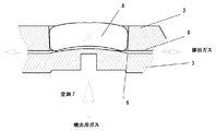
図1は、本発明の成形型の平面図(上図)および平面図(上図)のA-O-Bの垂直断面図(下図)である。尚、図中の白抜きの矢印は、ガスの流れを示す。
Hereinafter, the embodiment of the present invention will be described based on the example of the mold shown in FIG.
FIG. 1 is a plan view (upper view) and a vertical sectional view (lower view) of the AOB in the plan view (upper view) of the mold of the present invention. In addition, the white arrow in a figure shows the flow of gas.
成形型の本体1の上部にはガラス塊Aを収容する凹部2があり、凹部2は、開口を有し、底部の少なくとも一部にガス噴出口(図示せず)を有し、かつ前記底部3−1の少なくとも一部は成形面である。ガス噴出口は、例えば、凹部2の底部3−1を多孔質体3で構成することで、多孔質体の各孔が噴出口となることができる。図1では、多孔質体3の上面が凹部2の底部3−1となり、その少なくとも一部(底部3−1の中央部)はガラス塊Aの下面を成形する成形面となる。図1に示す態様の成形型においては、凹部2の底部3−1は全面が多孔質体3で形成されていることから、この態様では、凹部2の底部3−1は全面がガス噴出口を有する。
The
凹部2は、内周面を有する側壁部4を備え、側壁部4の内周面5の少なくとも一部は成形面である。側壁部4の内周面5の少なくとも一部は、プリフォームの側面を形成(成形)するための成形面として機能する。側壁部4の内側がガラス塊Aを収容し、成形するスペースとなる。側壁部4の内周面5は、例えば、円筒形状または裁頭円錐の側面形状(上方に行くにつれて内径が増加、すなわち上開き形状)とすることができる。
The
側壁部4は、底部3−1の成形面上方の空間の周囲を囲み、凹部2の底部3−1の周縁部及び/又は側壁部4の下端の少なくとも一部にガス噴出口より噴出する噴出ガスの少なくとも一部を凹部外へ導くガス排出口6を有する。
The side wall portion 4 surrounds the space above the molding surface of the bottom portion 3-1, and is ejected from the gas outlet to at least a part of the peripheral edge portion of the bottom portion 3-1 and / or the lower end of the side wall portion 4. A
ガス排出口6は、成形型1の外周面または上面に通じるガス排出路に連通する。成形型1の外周面または上面は、側壁部4の外周面または上面であることができる。具体的には、図1に示すように、側壁部4が、側壁部内周面5を含む部分4aが着脱可能であり、側壁部の着脱可能部4aは、外周面にセレーションを有する(図1上図参照)。セレーションは、外周面に上端面に対して垂直または傾斜した上端から下端まで連続するスリット4bを有することで形成されている。側壁部の着脱可能部4aのスリット4b下端は、内周面5側に連通する構造を有し、これにより、スリット4b下端はガス排出口6と連通する。側壁部4の着脱可能部4aと側壁部4の残りの部分(外周部4c)が一体となって側壁部4を構成し、着脱可能部4aのセレーション(スリット)を有する外周面と外周部4cの内面との間に、セレーション(スリット)に起因する隙間4bを形成し、この隙間4bがガス排出路となる。
The
側壁部の着脱可能部4aの外面と外周部4cの内面との間の隙間4bおよび側壁部の着脱可能部4aの一方の末端との間の隙間であるガス排出口6は、多孔質体3の上面(凹部底部3−1)が有するガス噴出口より噴出する噴出ガスを凹部外へ導くガス排出路として機能する。
The
側壁部の着脱可能部4aを、目的とするガラス塊の外径に相当する内径を有するものとして選択し、選択した側壁部4の着脱可能部4aを側壁部4の外周部4cに装着して使用すれば、側壁部全体を交換しなくても所望の外径のプリフォームを成形することができる。
The
凹部2の底部3−1は、側壁部の着脱可能部4aの下方の末端との間の少なくとも一部にガス排出口6を有する。図1の下図(A-O-B断面)では、描かれている底部3−1と側壁部の着脱可能部4aとの間には、両方ともガス排出口6が存在するが、A-O-B断面以外の部分には、底部3−1と側壁部の着脱可能部4aの下方の末端との間にスペーサ(例えば、側壁部の着脱可能部4aの下末端から延びる突起部)が設けられ、スペーサと底部3−1との間に隙間がなく直接接触している。但し、側壁部の外周部4cの内面を裁頭円錐の側面形状とし、側壁部の着脱可能部4aの外面も外周部4cの内面に対応する裁頭円錐の側面形状とすれば、前記スペーサがなくても、ガス排出口6のための隙間を設けた状態で、側壁部の着脱可能部4aを側壁部の外周部4cの内部に保持することもできる。
The bottom part 3-1 of the recessed
ガス排出口6は、後述するガスクッションの厚みを均一に近づけるという観点からは、全周にわたり均等に配置することが望ましく、隙間(ガス排出路)4bも全周にわたり均等に配置することが望ましい。図示しない多孔質体と側壁部の間のスペーサ、本体1と側壁部の間のスペーサは、全周に沿って等間隔に配置することがガスの排出を軸対称にし、ガスクッションの厚さを均等に近づける上から好ましい。
From the viewpoint of making the thickness of the gas cushion, which will be described later, uniform, the
こうした構造の成形型では、ガラス塊の量を所定量以上とすれば、ガラス塊側面を全周にわたって側壁部内周面により精密に規制することができる。すなわち、ガスクッションを介してガラス塊側面を規制するのとは異なり、ガラス塊の外径を精度よく成形することができる。 In the mold having such a structure, when the amount of the glass lump is set to a predetermined amount or more, the side surface of the glass lump can be precisely regulated by the inner peripheral surface of the side wall portion over the entire circumference. That is, unlike the regulation of the glass lump side surface via the gas cushion, the outer diameter of the glass lump can be accurately formed.
側壁部内周面を前述のように円筒形状もしくは裁頭円錐の側面形状など上開き形状にすることで、成形後にガラスを上方に持ち上げて側壁部から円滑に抜き取りやすくすることができる。例えば、側壁部は、ステンレス製とすることができ、表面にメッキを施したものであることが好ましい。特に、側壁部内周面にクロムメッキ等のメッキを施すことで、高温のガラスとの融着を防ぐことができ、好ましい。さらに、こうしたメッキは融着を防止だけでなく、成形したガラスをスムーズに取り出す上からも有効である。 By making the inner peripheral surface of the side wall part into an open shape such as a cylindrical shape or a side surface shape of a truncated cone as described above, the glass can be lifted upward after molding to facilitate smooth extraction from the side wall part. For example, the side wall portion can be made of stainless steel, and the surface is preferably plated. In particular, it is preferable to perform plating such as chrome plating on the inner peripheral surface of the side wall portion because fusion with high-temperature glass can be prevented. Furthermore, such plating is effective not only for preventing fusion but also for taking out the molded glass smoothly.
多孔質体3の下部には空洞7を設けることができ、空洞7には図示しないガス供給路から高圧ガスが供給される構造とすることができる。多孔質体3の下面3−2は上記空洞7に接しており、側面3−3および上面の周辺部3−4は、側壁部4の下部に密接に当接されている。
A
空洞7に高圧ガスを供給すると底部(成形面)3−1より前記ガスが噴出するが、この状態で底部(成形面)3−1上の側壁部4の内周面5で囲まれた空間に軟化状態のガラス塊Aを供給すると、ガラス塊Aは自重により変形し、ガラス塊Aの側面が側壁部内周面5に接触し、多孔質体から噴出するガスは、底部3−1の成形面とガラス塊Aの間にガスクッションを形成しつつ、ガス排出口6から隙間(ガス排出路)4bを通って凹部2の外へ排出する。このようにガス排出口6及び隙間4bは多孔質体から噴出したガスの排出路として機能する。
When high pressure gas is supplied to the
成形面から噴出するガスの圧力分布は、底部(成形面)3−1の形状によって、最適化することが望ましい。例えば、底部(成形面)3−1を軸対称な凸面としたとき、成形面の中央付近で噴出ガスがスムーズに排出されず、成形面とガラス塊下面の間に閉じ込められやすい。こうしたガスの閉じ込めがおきると、ガラス塊下面の形状が意図した形状からずれてしまう。このような場合、底部(成形面)3−1の中央における単位面積あたりのガス噴出量を底部(成形面)3−1の周辺部における量より少なく調整することができる。この調整は、例えば、多孔質体下面3−2の中央に窪み3−5を形成し、窪み3−5の底部3−6を目止めすることが行うことができる。こうすることで高圧ガスは底部3−6を通ることができず、底部(成形面)3−1の中央からは底部3−6の周辺から多孔質体の中を回り込んだガスだけが噴出する。また、窪み3−5の深さを深くするほど、目止めした底部3−6の周辺を回り込むガス量が少なくなり、底部(成形面)3−1の中央から噴出するガス量が少なくなり、窪み3−5の深さを浅くすれば、底部(成形面)3−1の中央から噴出するガス量の減少は小さくなる。このように窪み3−5の内径とともに深さを調整することにより、成形面から噴出するガス量の分布を制御することができ、成形面中央におけるガスの閉じ込めを回避することができる。 It is desirable to optimize the pressure distribution of the gas ejected from the molding surface according to the shape of the bottom (molding surface) 3-1. For example, when the bottom (molding surface) 3-1 is an axisymmetric convex surface, the jet gas is not smoothly discharged near the center of the molding surface, and is easily trapped between the molding surface and the lower surface of the glass lump. When such gas confinement occurs, the shape of the lower surface of the glass lump deviates from the intended shape. In such a case, the amount of gas ejection per unit area at the center of the bottom (molding surface) 3-1 can be adjusted to be less than the amount at the periphery of the bottom (molding surface) 3-1. This adjustment can be performed, for example, by forming a recess 3-5 in the center of the lower surface 3-2 of the porous body, and closing the bottom 3-6 of the recess 3-5. By doing so, the high-pressure gas cannot pass through the bottom 3-6, and only the gas that has entered the porous body from the periphery of the bottom 3-6 is ejected from the center of the bottom (molding surface) 3-1. To do. Moreover, the deeper the depth of the recess 3-5, the smaller the amount of gas that goes around the perimeter of the bottom 3-6 that has been sealed, and the lesser the amount of gas that is ejected from the center of the bottom (molded surface) 3-1. If the depth of the recess 3-5 is reduced, the reduction in the amount of gas ejected from the center of the bottom (molding surface) 3-1 is reduced. Thus, by adjusting the depth together with the inner diameter of the recess 3-5, the distribution of the amount of gas ejected from the molding surface can be controlled, and gas confinement at the center of the molding surface can be avoided.
こうしたガス噴出量分布の制御は、底部(成形面)3−1の形状が平面の場合にも有効である。また、底部(成形面)3−1の形状が凹面の場合も、凸面や平面の場合より顕著でないものの有効である。 Such control of the gas ejection amount distribution is also effective when the shape of the bottom (molding surface) 3-1 is a plane. In addition, even when the shape of the bottom portion (molding surface) 3-1 is concave, it is effective although it is less remarkable than the case of a convex surface or a flat surface.
このようにして多孔質体から噴出するガスによりガラス塊に上向きの風圧が加わり、ガラス塊が浮上して、多孔質体と非接触の状態で成形される。高温のガラス塊が成形型に直接接触すると、型との接触部分が局部的に急冷されてガラス表面にシワが生じる。上記のようにガラス塊を浮上させて高温のガラスが型の成形面に実質的に接触しないようにすれば、シワのない滑らかな表面のプリフォームを成形することができる。ガラス塊の下面は多孔質体の成形面と継続的に接触することはないが、上記ガスクッションが均一な厚みになるように、噴出ガスの流量等を調整すれば、成形面の形状がガラス塊下面に転写成形される。したがって、目的とするガラス塊の下面形状の反転形状に成形面を加工することで、所望形状の下面を有するガラスを成形することができる。図1の成形型の成形面は凸面であり、この成形型を用いると下面形状が凹面のプリフォームを成形することができる。 In this way, an upward wind pressure is applied to the glass lump by the gas ejected from the porous body, the glass lump floats and is molded in a non-contact state with the porous body. When the high-temperature glass lump comes into direct contact with the mold, the contact portion with the mold is locally quenched to cause wrinkles on the glass surface. If the glass lump is floated as described above so that the high-temperature glass does not substantially contact the molding surface of the mold, a preform having a smooth surface without wrinkles can be molded. The lower surface of the glass lump does not continuously come into contact with the molding surface of the porous body, but if the flow rate of the jet gas is adjusted so that the gas cushion has a uniform thickness, the shape of the molding surface is glass. Transfer molded on the bottom surface of the lump. Therefore, the glass having the lower surface of the desired shape can be formed by processing the molding surface into the inverted shape of the lower surface shape of the target glass lump. The molding surface of the mold shown in FIG. 1 is a convex surface. By using this mold, a preform having a concave bottom surface can be molded.
図2は、成形面を凹面とした本発明の成形型の平面図(上図)および平面図(上図)のA-O-Bの垂直断面図(下図)である。この成形型を用いると、ガラス塊の下面を凸面に成形することができる。成形型の構成は、成形面が凹面であること、多孔質体下面の中央部に窪みや目止めを設けないこと以外は、図1に示した成形型と実質的に同じである。 FIG. 2 is a plan view (upper view) and a vertical cross-sectional view (lower view) of A-O-B in the plan view (upper view) of the molding die of the present invention having a concave molding surface. When this mold is used, the lower surface of the glass block can be formed into a convex surface. The configuration of the molding die is substantially the same as that of the molding die shown in FIG. 1 except that the molding surface is a concave surface and no depression or seal is provided in the central portion of the lower surface of the porous body.
図3は、図1と同様に成形面を凸面とした本発明の成形型の垂直断面図である。この成形型は、側壁部4が一体型であり、ガス排出路8は、側壁部4の底部と多孔質体3の上面の間に設けられる。ガス排出路8の凹部2内部側の末端は、ガス排出口6となる。成形型の構成は、側壁部4が一体型であり、ガス排出路8が側壁部4の底部と多孔質体3の上面の間に設けられる成形面が凹面であること以外は、図1に示した成形型と実質的に同じである。ガス排出路8は、放射状に均等な間隔で設けることが、上記ガスクッションが均一な厚みになるという観点から好ましい。
FIG. 3 is a vertical sectional view of the molding die of the present invention in which the molding surface is convex as in FIG. In this molding die, the side wall 4 is an integral type, and the
[精密プレス成形用プリフォームの製造方法]
次に、本発明の精密プレス成形用プリフォームの製造方法について説明する。
本発明の精密プレス成形用プリフォームの製造方法は、熔融ガラス塊を成形して精密プレス成形用プリフォームを得る精密プレス成形用プリフォームの製造方法である。
[Precision press molding preform manufacturing method]
Next, the manufacturing method of the precision press molding preform of this invention is demonstrated.
The method for producing a precision press-molding preform according to the present invention is a method for producing a precision press-molding preform by molding a molten glass lump to obtain a precision press-molding preform.
本発明の製造方法は、
(1)上記の本発明の成形型を用い、この成形型の成形面上の側壁部で囲まれた空間に熔融ガラス塊を供給する工程、および
(2)成形面からガスを噴出して該ガラス塊に風圧を加えて浮上させながら、
前記側壁部の内面にガラス塊の側面を接触させて、側面を有するプリフォームを成形する工程を有する。
The production method of the present invention comprises:
(1) Using the mold of the present invention described above, supplying a molten glass lump to the space surrounded by the side wall on the molding surface of the mold, and (2) ejecting gas from the molding surface While applying wind pressure to the glass lump,
A step of bringing a side surface of the glass block into contact with the inner surface of the side wall portion and molding a preform having the side surface;
(1)熔融ガラス塊の供給
本発明の製造方法では、成形面上の側壁部の内周面で囲まれた空間(成形スペース)に熔融ガラス塊を供給する。例えば、公知の方法により熔解、清澄、均質化された熔融ガラスをパイプから一定流量で流出して熔融ガラス流の下端を上記成形型の成形面で受ける。このとき、成形面からガスを噴出してガスクッションを介して熔融ガラスを受けてもよいし、成形面に直接受けてもよい。この状態で熔融ガラス流には表面張力によるくびれが生じる。次に成形型を下方に急降下させて表面張力によって前記くびれで熔融ガラスを分離する。こうしてくびれより下の熔融ガラスが成形型の凹部に供給される。成形型の代わりに熔融ガラス流の下端を受ける受け具を用い、所定のタイミングで受け具を急降下して熔融ガラス塊を分離し、得られた熔融ガラス塊を成形型の凹部に供給してもよい。
(1) Supply of molten glass lump In the manufacturing method of this invention, a molten glass lump is supplied to the space (molding space) enclosed by the internal peripheral surface of the side wall part on a molding surface. For example, molten glass that has been melted, clarified, and homogenized by a known method flows out from a pipe at a constant flow rate, and the lower end of the molten glass flow is received by the molding surface of the mold. At this time, gas may be ejected from the molding surface and the molten glass may be received via a gas cushion, or may be received directly on the molding surface. In this state, the molten glass flow is constricted by surface tension. Next, the mold is lowered rapidly, and the molten glass is separated by the constriction by surface tension. In this way, the molten glass below the constriction is supplied to the concave portion of the mold. Even if a receiving tool that receives the lower end of the molten glass flow is used instead of the forming mold, the receiving glass is rapidly lowered at a predetermined timing to separate the molten glass lump, and the obtained molten glass lump is supplied to the recess of the forming mold. Good.
(2)浮上成形
凹部に供給された熔融ガラス塊の粘度は低く、側壁部の内周面で囲まれた空間内に広がる。凹部の底部からはガスが噴出しているので、前述のようにガラス塊は浮上状態になり、成形面とガラスの間にガスクッションが形成される。しかし、噴出ガスはガス排出路から優先的に排出されるため、ガラスと側壁部内周面の間にはガスクッションは実質的に形成されず、ガラス側面と側壁部とが直接接触する。こうして熔融ガラス塊は、底面は成形面の形状を転写した形状を有し、かつ側面を有するプリフォームに成形される。プリフォームに成形される側面の形状は、側壁部内周面の形状を選択することで適宜選択でき、側面の高さは、側壁部を含む成形型が同一の場合、供給される熔融ガラス塊の量に応じて、増減する。
(2) Floating molding The viscosity of the molten glass lump supplied to the recess is low and spreads in the space surrounded by the inner peripheral surface of the side wall. Since gas is ejected from the bottom of the recess, the glass lump is floated as described above, and a gas cushion is formed between the molding surface and the glass. However, since the jet gas is preferentially discharged from the gas discharge path, a gas cushion is not substantially formed between the glass and the inner peripheral surface of the side wall, and the glass side surface and the side wall are in direct contact. Thus, the molten glass lump is molded into a preform having a shape obtained by transferring the shape of the molding surface on the bottom surface and having a side surface. The shape of the side surface molded into the preform can be selected as appropriate by selecting the shape of the inner peripheral surface of the side wall, and the height of the side surface is the same as that of the molten glass lump supplied when the mold including the side wall is the same. Increase or decrease depending on the amount.
噴出ガスの量は、噴出ガスが前記ガス噴出口から排出されるとともに、前記熔融ガラス塊が前記側壁部で囲まれた空間を閉塞し得るように設定される。前記噴出ガスは、成形型の凹部の底部と側壁部の下端との間に設けられた隙間であるガス排出口からガス排出路を介して凹部(成形型)外へと排出される。前記ガスの噴出量が過剰だと、ガス排出路から排出しきれないガスが、熔融ガラス塊と側壁部の間に入り込んだり、熔融ガラス塊中に入り込んでガラス塊の変形や気泡の混入を引き起こし、品質を低下させることになる。したがって、上記ガスの噴出量は、側壁部の内面5で囲まれた空間(成形スペース)が熔融ガラス塊により閉塞され、かつ、熔融ガラス塊が成形スペース内で浮上するに適した量に設定することが適当である。そして、こうした状態が維持されるよう、前記ガスの噴出量を制御することが、目的とするガラス塊を高品質かつ安定して製造する上から好ましい。
The amount of the ejection gas is set so that the ejection gas is discharged from the gas ejection port and the molten glass lump can block the space surrounded by the side wall portion. The ejected gas is discharged out of the recess (mold) from a gas discharge port which is a gap provided between the bottom of the recess of the mold and the lower end of the side wall. If the gas ejection amount is excessive, the gas that cannot be exhausted from the gas discharge passage enters between the molten glass lump and the side wall, or enters the molten glass lump, causing deformation of the glass lump and mixing of bubbles. , Will reduce the quality. Therefore, the gas ejection amount is set to an amount suitable for the space (molding space) surrounded by the
熔融ガラス塊の量
本発明の製造方法においては、熔融ガラス塊の量と側壁部の内周面で囲まれた空間(成形スペース)とは、側面を有するプリフォームを成形するためには、一定の関係を有することが必要である。少なくとも過少量の熔融ガラス塊を側壁部の内周面で囲まれた空間(成形スペース)に供給しても、側面を有するプリフォームを成形することはできない。そこで、成形型に供給される熔融ガラス塊は、側壁部の内周面で囲まれた空間を閉塞して、噴出ガスがガス排出口から排出され得る量に設定される。具体的には、例えば、側壁部の内周面で囲まれた空間(成形スペース)の容量を100とした場合、熔融ガラス塊の容量を65〜111の範囲とすることができる。但し、この比率の適切な範囲は、側壁部の内周面で囲まれた空間(成形スペース)の開口寸法と深さによっても変化する。上記範囲は、側壁部の内周面で囲まれた空間(成形スペース)の開口寸法と深さの比が1.75〜2.72の範囲の場合である。この開口寸法と深さの比を外れる場合でも、開口寸法と深さの比を考慮すれば、上記側壁部の内周面で囲まれた空間(成形スペース)の容量と熔融ガラス塊の容量の比は適宜設定することができる。
In the production method of the present invention, the amount of molten glass lump and the space (molding space) surrounded by the inner peripheral surface of the side wall portion are constant for molding a preform having side surfaces. It is necessary to have the relationship of Even if at least a small amount of molten glass ingot is supplied to the space (molding space) surrounded by the inner peripheral surface of the side wall portion, a preform having side surfaces cannot be molded. Therefore, the molten glass lump supplied to the mold is set to an amount capable of closing the space surrounded by the inner peripheral surface of the side wall and ejecting the gas from the gas outlet. Specifically, for example, when the capacity of the space (molding space) surrounded by the inner peripheral surface of the side wall is 100, the capacity of the molten glass lump can be in the range of 65 to 111. However, the appropriate range of this ratio varies depending on the opening size and depth of the space (molding space) surrounded by the inner peripheral surface of the side wall. The said range is a case where ratio of the opening dimension and depth of the space (molding space) enclosed by the inner peripheral surface of the side wall part is in the range of 1.75 to 2.72. Even when the ratio between the opening dimension and the depth is out of consideration, if the ratio between the opening dimension and the depth is taken into consideration, the capacity of the space (molding space) surrounded by the inner peripheral surface of the side wall and the capacity of the molten glass lump The ratio can be set as appropriate.
ガラス塊の上面は、形状をコントロールするための特段の操作をしない場合は、ガラスに働く重力と表面張力などによって、凸状の曲面に成形される。こうした形状以外にガラス塊の上面を成形したい場合は、例えば、ガラス上面を非接触で吸引して、ガラス上面の中央に負圧を与えて前記中央を盛り上げること、ガスを前記上面にガスを吹き付けて窪ませること、前記上面をプレスすることなどの操作を行うことができる。 When the special operation for controlling the shape is not performed, the upper surface of the glass block is formed into a convex curved surface by gravity and surface tension acting on the glass. If you want to shape the upper surface of the glass lump in addition to these shapes, for example, suction the upper surface of the glass in a non-contact manner, apply a negative pressure to the center of the upper surface of the glass to raise the center, and blow a gas on the upper surface. Such as pressing the upper surface and pressing the upper surface.
この中で上面形状を最も精密に成形するという観点からは、上型を用いて成形型に収容されているガラス塊をプレスする方法が好ましい。図4は、図1の成形型に収容されたガラス塊を、上型10を用いてプレスした例である。上型10の成形面10−1は凸状の曲面であり、前記プレスによってガラス塊上面の形状が成形面10−1の反転形状に成形される。
Among these, from the viewpoint of forming the upper surface shape most precisely, a method of pressing the glass block accommodated in the forming die using the upper die is preferable. FIG. 4 is an example in which the glass block accommodated in the mold shown in FIG. 1 is pressed using the
熔融ガラスの成形型への供給工程における流出時の熔融ガラスの粘度は、例えば、3.8〜4.5dPa・sの範囲であることができ、成形型の凹部に供給される熔融ガラス塊の粘度は9〜60dPa・sの範囲であることができる。また、浮上成形時のガラス塊の粘度は60〜103dPa・sの範囲であることができる。さらに、上記プレス時のガラス塊の粘度は1.2×10²〜1.1×10⁴dPa・s、好ましくは1.2×10²〜103dPa・sとすることがプリフォームの形状精度を高める上から望ましい。多孔質体からガスを噴出した状態でプレスすることにより、多孔質体の微小孔へのガラスの侵入を防ぐことができる。ただし、多孔質体からのガス噴出量が多すぎるとガラス塊下面と成形面の間にガスが閉じ込められて前記下面の形状が所望形状からずれてしまう場合がある。そこで、プレス時には多孔質体からのガス噴出量をプレス開始前より減少させることが望ましく、プレス終了後に前記ガス噴出量をプレス時より増加させることが望ましい。 The viscosity of the molten glass at the time of outflow in the process of supplying molten glass to the mold can be, for example, in the range of 3.8 to 4.5 dPa · s, and the viscosity of the molten glass lump supplied to the recess of the mold. The viscosity can range from 9 to 60 dPa · s. Moreover, the viscosity of the glass lump at the time of float forming can be in the range of 60 to 10 3 dPa · s. Furthermore, the viscosity of the glass lump at the time of pressing is 1.2 × 10 2 to 1.1 × 10 4 dPa · s, preferably 1.2 × 10 2 to 10 3 dPa · s. It is desirable for improving accuracy. By pressing in a state where gas is ejected from the porous body, glass can be prevented from entering the micropores of the porous body. However, if the amount of gas ejected from the porous body is too large, gas may be trapped between the lower surface of the glass lump and the molding surface, and the shape of the lower surface may deviate from the desired shape. Therefore, it is desirable to reduce the gas ejection amount from the porous body at the time of pressing than before the start of pressing, and it is desirable to increase the gas ejection amount after the pressing from the time of pressing.
ガス噴出量の増加減少量については、実際に成形を行い、噴出量を変化させてガラス塊下面に多孔質体表面の微細な凹凸がガラスに転写されず(プリフォーム表面が滑らかになるよう)、高温のガラス塊と型の接触によるシワが表面にできないように前記増加減少量を調整する。 As for the increase and decrease of the gas ejection amount, the molding is actually performed and the ejection amount is changed so that the fine irregularities on the porous body surface are not transferred to the glass underside of the glass lump (so that the preform surface becomes smooth) The increase / decrease amount is adjusted so that the surface is not wrinkled by contact between the hot glass block and the mold.
成形工程でガラス塊をプレスする場合、ガラス塊の側面は側壁部内周面によって規制され、前記内周面は凹凸のない曲面(好ましくは円筒形状または裁頭円錐の側面形状)なので、プレスされたガラスが上記内周面のへこみに進入することがない。したがって、凹部からプリフォームを取り出す際、内周面のへこみに進入したガラスが取り出しを妨げることもなく、スムーズな取り出しが可能になる。 When pressing the glass lump in the molding process, the side surface of the glass lump is regulated by the inner peripheral surface of the side wall, and the inner peripheral surface is a curved surface (preferably a cylindrical shape or a truncated conical side shape). Glass does not enter the dent of the inner peripheral surface. Therefore, when the preform is taken out from the concave portion, the glass that has entered the dent on the inner peripheral surface does not hinder the taking out and can be taken out smoothly.
このようにして側面が円筒形状または裁頭円錐の側面形状であって、対向する2つの端面が平面または曲面のプリフォームを成形することができる。端面の形状は成形型の成形面の形状、プレスする場合は加えて上型成形面の形状の反転形状になる。したがって、前記成形面の形状を適宜選択することにより、両端面がともに凸曲面、凹曲面、平面のいずれかのプリフォーム、あるいは、一方の端面が凸曲面で他方の端面が凹曲面、一方の端面が凸曲面で他方の端面が平面、一方の端面が平面で他方の端面が凹曲面、のいずれかのプリフォームを成形することができる。 In this way, it is possible to form a preform having a cylindrical side surface or a truncated cone side surface and two opposing end surfaces being flat or curved. The shape of the end surface is the shape of the molding surface of the mold, and in the case of pressing, the shape of the upper mold surface is reversed. Therefore, by appropriately selecting the shape of the molding surface, both the end surfaces are either a convex curved surface, a concave curved surface, or a flat preform, or one end surface is a convex curved surface and the other end surface is a concave curved surface. It is possible to form a preform having an end surface that is a convex curved surface, the other end surface is a flat surface, one end surface is a flat surface, and the other end surface is a concave curved surface.
成形型からプリフォームを取り出すときは、プリフォーム上面を吸引具で吸引して保持し、真上に持ち上げて成形型から取り出し、徐冷する。なお、必要に応じてプリフォーム表面の一部または全部を研磨してもよい。 When taking out the preform from the mold, the upper surface of the preform is sucked and held with a suction tool, lifted right above, taken out from the mold, and slowly cooled. If necessary, a part or all of the preform surface may be polished.
[精密プレス成形用プリフォーム]
次に本発明の方法で製造されるプリフォームの具体例について説明する。
上記プリフォームの一例は、回転対称軸を有し、かつ前記回転対称軸と各々交差する2つの端面及び前記2つの端面の外周に接続する1つの側面を備える、ガラス製の精密プレス成形用プリフォームである。さらに、本発明のプリフォームの前記2つの端面は、被プレス面であり、かつ独立に凸面または凹面であり、前記側面は熔融状態のガラスを固化して得られた面からなる。さらに、このプリフォームは、前記回転対称軸に一致する軸を有し、かつ前記プリフォームに外接する仮想的な円柱を想定したときに、当該円柱の高さhに対する直径φの比(φ/h)が1以上かつ3以下である。さらに、前記円柱の容積V0に対する前記プリフォームの体積Vの比(V/V0)が68%以上である。
[Preform for precision press molding]
Next, specific examples of the preform manufactured by the method of the present invention will be described.
An example of the above preform is a glass precision press-molding preform having two end faces each having a rotational symmetry axis and one side face connected to the outer periphery of each of the two end faces. It is a reform. Furthermore, the two end surfaces of the preform of the present invention are pressed surfaces and are independently convex surfaces or concave surfaces, and the side surfaces are surfaces obtained by solidifying molten glass. Furthermore, when the preform has an axis that coincides with the rotational symmetry axis and is assumed to be a virtual cylinder circumscribing the preform, the ratio of the diameter φ to the height h of the cylinder (φ / h) is 1 or more and 3 or less. Furthermore, the ratio (V / V 0 ) of the volume V of the preform to the volume V 0 of the cylinder is 68% or more.
上記プリフォームは、回転対称軸を有し、かつ前記回転対称軸と各々交差する2つの端面及び前記2つの端面の外周に接続する1つの側面を備える。 The preform includes two end faces each having a rotational symmetry axis and intersecting the rotational symmetry axis, and one side face connected to the outer periphery of the two end faces.
レンズのように光学機能面の形状が極めて高い回転対称性を有する光学素子を成形するには、回転対称軸を有するプリフォームを用いることが適切である。回転対称軸のまわりに任意の角度だけ回転する操作に対し、回転前後のプリフォームの輪郭を重ね合わせることができる。ただし、この回転対称性は、幾何学的に厳密である必要はなく、精密プレス成形によって所望の光学素子を作製できる程度であればよい。 In order to form an optical element having an extremely high rotational symmetry such as a lens and having a very high optical function surface shape, it is appropriate to use a preform having a rotationally symmetric axis. The contour of the preform before and after the rotation can be superimposed on the operation of rotating by an arbitrary angle around the rotational symmetry axis. However, this rotational symmetry does not need to be exact geometrically, and it is sufficient if it can produce a desired optical element by precision press molding.
このプリフォームの典型的な形状は、円筒形であるが、純粋に円筒形であるものもみならず、2つの端面の一方または両方が凸面であることができる。さらに、側面が、回転対称軸と並行である場合と非並行である場合のいずれであることもできる。 The typical shape of this preform is cylindrical, but not purely cylindrical, and one or both of the two end faces can be convex. Further, the side surface can be either parallel or non-parallel to the rotational symmetry axis.
精密プレス成形によってガラスを均等に押し広げ、偏肉の少ない光学素子を得るには、回転対称軸の方向を向く面、すなわち、端面を精密プレス成形時の被プレス面とする。端面は凸面または凹面とすることができる。例えば、2つの端面とも凸面としたり、2つの端面と凹面としたり、2つの端面のうち、一方を凸面、他方を凹面とする。端面を凸面とするか凹面とするかは、成形するレンズなどの光学素子の形状を考慮して決めればよく、例えば、凹メニスカスレンズや凸メニスカスレンズを成形する場合は、2つの端面とも凸面とするか、2つの端面のうち、一方を凸面、他方を凹面とすることが好ましく、両凹レンズを成形する場合は、2つの端面とも凸面とするか、2つの端面とも凹面とするか、2つの端面のうち、一方を凸面、他方を凹面とすることが好ましい。そして、端面の曲率をプレス成形型の成形面の形状にあわせて決めることにより、精密プレス成形時のガストラップを防止することができる。 In order to obtain an optical element that spreads the glass evenly by precision press molding and has a small thickness deviation, the surface facing the direction of the rotational symmetry axis, that is, the end surface is used as a surface to be pressed during precision press molding. The end face can be convex or concave. For example, both end surfaces are convex surfaces, two end surfaces and concave surfaces, or one of the two end surfaces is convex and the other is concave. Whether the end surface is a convex surface or a concave surface may be determined in consideration of the shape of an optical element such as a lens to be molded. For example, when molding a concave meniscus lens or a convex meniscus lens, both end surfaces are convex surfaces. It is preferable that one of the two end surfaces is a convex surface and the other is a concave surface. When a biconcave lens is molded, either the two end surfaces are convex surfaces or the two end surfaces are concave surfaces. Of the end surfaces, it is preferable that one is a convex surface and the other is a concave surface. And the gas trap at the time of precision press molding can be prevented by determining the curvature of the end face according to the shape of the molding surface of the press mold.
端面が凸面または凹面である場合、その曲率は、プレス成形型の成形面が球面の場合には当該球面、前記成形面が非球面の場合には当該非球面の非球面式の基準曲率等を考慮して、適宜決定できる。2つの端面の曲率は、同一または異なることができる。 When the end surface is a convex surface or a concave surface, the curvature is the spherical surface when the molding surface of the press mold is a spherical surface, and the aspherical reference curvature of the aspherical surface when the molding surface is an aspheric surface. It can be determined as appropriate in consideration. The curvatures of the two end faces can be the same or different.
さらに、前記凸面には、凸面の回転対称軸との交点を含む領域に凹部を備えることもできる。凹部の大きさ(凸面に対する割合)は、レンズの光学機能面が球面であれば当該球面の曲率、非球面であれば当該非球面の非球面式の基準曲率等を考慮して適宜決定できる。例えば、前記レンズの光学機能面の直径をdとすると前記凹部の直径はd/3〜d/2の範囲とすることができる。凹部の深さはレンズの球欠等を考慮して適宜決定できる。例えば、高さhとすると凹部の深さはh/5〜h/4とすることができる。 Further, the convex surface may be provided with a concave portion in a region including an intersection with the rotational symmetry axis of the convex surface. The size of the concave portion (ratio to the convex surface) can be appropriately determined in consideration of the curvature of the spherical surface if the optical functional surface of the lens is a spherical surface, and the reference curvature of the aspherical surface of the aspherical surface if the surface is aspherical. For example, when the diameter of the optical functional surface of the lens is d, the diameter of the concave portion can be in the range of d / 3 to d / 2. The depth of the concave portion can be determined as appropriate in consideration of a lens notch or the like. For example, when the height is h, the depth of the recess can be set to h / 5 to h / 4.
また、端面(被プレス面)が凸面の場合、前記端面の回転対称軸との交点を含む領域に凹部を設けることにより、前記被プレス面を凸形状の型成形面でプレスする際、成形面の中心とプリフォームの中心を位置合せしやすくなる。また、精密プレス成形品の量産時、プレス成形型内にプリフォームを導入し、上記被プレス面の凹部を凸形状の成形面の頂部で押さえることにより、プリフォームを導入したプレス成形型を移動しても型内のプリフォームの位置を固定状態に保つこともできる。端面が凹面の場合であって、凹面の中心、すなわち、最も窪んだ部分が端面の回転対称軸との交点を含む領域である場合にもこうした効果を得ることができる。 Further, when the end surface (surface to be pressed) is a convex surface, a concave surface is provided in a region including the intersection with the rotational symmetry axis of the end surface, so that when the surface to be pressed is pressed with a convex mold surface, the molding surface It becomes easy to align the center of the preform and the center of the preform. Also, during mass production of precision press-molded products, the preform is introduced into the press mold, and the press mold with the preform introduced is moved by pressing the concave portion of the pressed surface with the top of the convex molding surface. Even so, the position of the preform in the mold can be kept fixed. Such an effect can also be obtained when the end surface is concave and the center of the concave surface, that is, the most depressed portion is a region including the intersection with the rotational symmetry axis of the end surface.
このプリフォームの側面の2つの外周縁は、2つの端面の外周のそれぞれに接続する。接続部分は、角を形成しているか、あるいは曲面であってもよい。あるいは、側面の2つの外周縁と端面の外周との間に、側面の2つの外周縁と端面の外周のそれぞれと接続する接続面が形成されていてもよい。 The two outer peripheral edges of the side surface of the preform are connected to the outer peripheries of the two end faces. The connecting portion may form a corner or may be a curved surface. Alternatively, a connection surface connected to each of the two outer peripheral edges of the side surface and the outer periphery of the end surface may be formed between the two outer peripheral edges of the side surface and the outer periphery of the end surface.
また、このプリフォームの側面は、円柱の側面形状または円柱の側面形状に近似する形状、もしくは裁頭円錐の側面形状または裁頭円錐の側面形状に近似する形状であることができる。このような形状のプリフォームによれば、充填率(V/V0)を一層高めることができる。円柱の側面形状とは、円柱断面の直径が断面のどの位置でも等しく、かつ側面の表面はなめらかな円柱に則したなめらかな曲面(曲平坦面)である。それに対して、円柱の側面形状に近似する形状とは、プリフォームの側面に後述する溝を備える場合など、幾何学的観点から厳密には円柱の側面形状ではないが、精密プレス成形やプリフォームの製造工程等の観点から円柱の側面形状と同等と見なせる形状を意味する。 Further, the side surface of the preform can be a side surface shape of a cylinder or a shape approximating a side surface shape of a cylinder, or a shape approximating a side shape of a truncated cone or a side shape of a truncated cone. According to the preform having such a shape, the filling rate (V / V 0 ) can be further increased. The side surface shape of the cylinder is a smooth curved surface (curved flat surface) in which the diameter of the cylinder cross section is equal at any position in the cross section and the surface of the side surface conforms to a smooth cylinder. On the other hand, the shape that approximates the shape of the side surface of the cylinder is not strictly the shape of the side surface of the cylinder from a geometrical point of view, such as when a groove that will be described later is provided on the side surface of the preform. This means a shape that can be regarded as equivalent to the side shape of a cylinder from the viewpoint of the manufacturing process.
また、裁頭円錐の側面形状は、円柱断面の直径が、一方の端面から他方の端面に向かって、減少または増加し、かつ側面の表面はなめらかな円柱に則したなめらかな曲面(曲平坦面)である。円柱断面の直径の減少または増加の程度は、プリフォームに要求される形状を考慮して適宜決定されるが、裁頭円錐の側面を側面の一部とする仮想的な円錐の頂角(全角2α)を4°〜6°の範囲にすることが、プリフォームの徐冷工程へ取り出しやすさという観点から適当である。なお、上記αは仮想的な円錐の中心軸と母線のなす角度(内角)である。 In addition, the side shape of the truncated cone is such that the diameter of the cross section of the cylinder decreases or increases from one end face to the other end face, and the side surface is a smooth curved surface (curved flat surface conforming to a smooth cylinder). ). The degree of decrease or increase in the diameter of the cylindrical section is appropriately determined in consideration of the shape required for the preform, but the apex angle (full angle) of a virtual cone with the side face of the truncated cone as a part of the side face It is appropriate that 2α) be in the range of 4 ° to 6 ° from the viewpoint of easy removal into the slow cooling step of the preform. Note that α is an angle (inner angle) formed by a central axis of a virtual cone and a generatrix.
精密プレス成形では、高粘度のガラスを高い圧力でプレスする。そして、このプリフォームはプレス時の変形量が大きいため、プリフォーム表面に研削痕や傷が存在すると、その部分を起点としてガラスが破損しやすい。こうしたトラブルを防ぐ上から、少なくともプリフォームの側面を熔融状態のガラスを固化して得られた面、好ましくは前記側面に加えて2つの端面(被プレス面)も熔融状態のガラスを固化して得られた面とする。熔融状態のガラスを固化して得られた面とは、プリフォーム全体あるいはプリフォームの母材となるガラス成形体全体を、熔融ガラスを冷却、固化して作ったときに得られるガラス表面を意味し、後述する火作り面、すなわち、ガラス表面のみを加熱、再熔融した後に固化して得られる面とは異なる。熔融状態のガラスを固化して得られた面には研削、研磨などの冷間加工が施されていないので、研削痕や研磨痕が存在せず、上記破壊の起点が存在しない。特に、上記観点から全表面が熔融状態のガラスを固化して得られた面であるプリフォームが好ましい。また、ガラス表面を再熔融した後、冷却、固化して得られる火作り面も、再熔融によって研削痕や研磨痕が修復されて、微視的にも平滑な面になるので、上記破壊の起点が存在しない。 In precision press molding, high-viscosity glass is pressed at high pressure. And since this preform has a large amount of deformation at the time of pressing, if there are grinding marks or scratches on the surface of the preform, the glass tends to be damaged starting from that portion. In order to prevent such troubles, at least the side surface of the preform is obtained by solidifying the molten glass, preferably the two side surfaces (surfaces to be pressed) in addition to the side surface also solidify the molten glass. The obtained surface. The surface obtained by solidifying molten glass means the glass surface obtained by cooling and solidifying the entire preform or the glass molded body that is the preform base material. However, it is different from the fire-making surface described later, that is, the surface obtained by heating and remelting only the glass surface and then solidifying. Since the surface obtained by solidifying the glass in the molten state is not subjected to cold working such as grinding and polishing, there is no grinding mark or polishing mark, and there is no origin of the destruction. In particular, a preform whose surface is obtained by solidifying glass in a molten state is preferable from the above viewpoint. In addition, after re-melting the glass surface, the fire-making surface obtained by cooling and solidifying the ground surface will be repaired by re-melting, so that the surface becomes microscopically smooth. There is no starting point.
火作り面はファイヤーポリッシュと呼ばれる方法で得られる。しかし、火作り面ではガラス表面を高温に再加熱するため、ガラス表面が変質するおそれがある。特に、B2O3、アルカリ金属、フッ素、塩素などの揮発しやすい成分を含むガラスでは、ファイヤーポリッシュ時に揮発によってガラス表面が変質しやすい。また、一端、所望の形状に成形したガラスを再加熱、再熔融するため、ガラスが所望形状から変形してしまう。このような理由で、火作り面と熔融状態のガラスを固化して得られた面とを比較すると後者のほうが格段優れている。鏡面研磨面は、荒ずり、砂かけなどのラッピング工程を経た後、ポリシングされた面である。ラッピングされた面には多数の研削痕、研磨痕が存在し、これらが上記破壊の起点になる。鏡面研磨面では、こうした起点のうち大きなものは除去されるが、潜傷と呼ばれる極めて微細な傷が存在するため、鏡面研磨面を有するプリフォームは、熔融状態のガラスを固化して得られた面や火作り面によって全表面が構成されるプリフォームに比べて耐破損性が低くなる。エッチング面も研削痕や研磨痕がエッチングにより除去されるので、表面がエッチング面のプリフォームも耐破壊性に優れている。ただし、潜傷がある表面をエッチングすると、傷が顕在化することにより耐破壊性が低下することがある。いずれにしても熔融状態のガラスを固化して得られる面とすることが格段と好ましい。 The fire-making surface is obtained by a method called fire polish. However, since the glass surface is reheated to a high temperature on the fire-making surface, the glass surface may be altered. In particular, in a glass containing a component that tends to volatilize such as B 2 O 3 , alkali metal, fluorine, and chlorine, the glass surface is likely to be altered by volatilization during fire polishing. Moreover, since the glass shape | molded at the end and the desired shape is reheated and remelted, glass will deform | transform from a desired shape. For this reason, when comparing the fire-making surface with the surface obtained by solidifying glass in the molten state, the latter is much better. The mirror-polished surface is a polished surface after a lapping process such as roughening or sanding. There are a number of grinding marks and polishing marks on the lapped surface, and these are the starting points of the destruction. On the mirror-polished surface, large ones of these starting points are removed, but because there are very fine scratches called latent scratches, a preform having a mirror-polished surface was obtained by solidifying molten glass. Breakage resistance is lower than a preform whose entire surface is composed of a surface and a fire-making surface. Since the grinding marks and polishing marks are also removed by etching on the etched surface, the preform whose surface is the etched surface is also excellent in fracture resistance. However, if a surface having a latent flaw is etched, the flaw resistance may be reduced due to the appearance of the flaw. In any case, it is particularly preferable to obtain a surface obtained by solidifying molten glass.
なお、熔融状態のガラスを固化して得られた面の例としては、自由表面、型成形面を熔融ガラスに転写して得られる型転写面などをあげることができる。自由表面は、例えば、熔融ガラス塊を浮上しながら成形することによって形成することができる。型転写面はプレス成形型でガラスをプレスしたり、熔融ガラスを鋳型に流し込むことによって形成することができる。 Examples of the surface obtained by solidifying the molten glass include a free surface and a mold transfer surface obtained by transferring the mold forming surface to the molten glass. The free surface can be formed, for example, by forming a molten glass lump while floating. The mold transfer surface can be formed by pressing glass with a press mold or pouring molten glass into a mold.
このプリフォームは、形状を、プリフォームに外接する仮想的な円柱の高さhに対する直径φの比(φ/h)が1以上かつ3以下となるように調整したものである。比(φ/h)が1より小さいと、側面部分または側面と端面(被プレス面)の境界部分がレンズの有効径内に入ってしまい、レンズ表面の品質を低下させるおそれが高くなる。一方、比(φ/h)が3より大きいと、精密プレス成形時のガラスの変形量が小さくなり、ガラスを成形面全域に行き渡らせるのが難しくなる。また、プリフォームがプレス成形型の中で傾いて、レンズの偏肉・偏芯の原因になるおそれがある。したがって、比(φ/h)を上記範囲にするが、比(φ/h)の好ましい範囲は1〜2.6、より好ましい範囲は1〜2.4、さらに好ましい範囲は1〜2.0とする。 In this preform, the shape is adjusted so that the ratio (φ / h) of the diameter φ to the height h of a virtual cylinder circumscribing the preform is 1 or more and 3 or less. When the ratio (φ / h) is smaller than 1, the side surface portion or the boundary portion between the side surface and the end surface (pressed surface) falls within the effective diameter of the lens, and there is a high possibility that the quality of the lens surface is deteriorated. On the other hand, if the ratio (φ / h) is larger than 3, the amount of deformation of the glass during precision press molding becomes small, and it becomes difficult to spread the glass over the entire molding surface. In addition, the preform may be tilted in the press mold, which may cause lens thickness deviation or eccentricity. Therefore, the ratio (φ / h) is set to the above range, but the preferable range of the ratio (φ / h) is 1 to 2.6, more preferably 1 to 2.4, and still more preferably 1 to 2.0.
全表面が熔融状態のガラスを固化して得られた面であるプリフォームを作製する上からも、本発明のプリフォームの形状は好都合である。全表面が熔融状態のガラスを固化して得られた面であるプリフォームの作製では、後述するように熔融ガラス塊に風圧を加えて浮上させながら成形する。このとき、ガラス塊底面にガスを吹き付けて浮上させる風圧を得るが、φ/hが大きすぎると前記ガスがガラス塊の底面から側面に沿って抜けにくくなり、ガラス塊を安定して浮上させるのが困難になる。一方、φ/hが小さすぎるとガラス塊の底面に加わる風圧だけでガラス塊を浮上させることが困難になる。φ/hが上記の範囲にあることにより、ガラス塊を安定して浮上させながら成形することもできる。なお、ガラス塊の浮上の安定化の観点からもφ/hの好ましい範囲は前述の範囲となる。 The shape of the preform of the present invention is also advantageous from the viewpoint of producing a preform whose entire surface is a surface obtained by solidifying molten glass. In preparation of a preform whose entire surface is a surface obtained by solidifying glass in a molten state, the molten glass lump is molded while being floated by applying wind pressure as described later. At this time, a wind pressure is obtained by blowing a gas to the bottom surface of the glass lump to obtain a wind pressure. However, if φ / h is too large, the gas is difficult to escape from the bottom surface of the glass lump along the side surface, and the glass lump is stably floated. Becomes difficult. On the other hand, if φ / h is too small, it is difficult to float the glass lump only by the wind pressure applied to the bottom surface of the glass lump. When φ / h is in the above range, the glass lump can be molded while being stably floated. From the viewpoint of stabilizing the floating of the glass lump, the preferable range of φ / h is the above-described range.
このようにして精密プレス成形時のガラスの変形量を確保した上で、ガラスの成形面からのはみ出し量を低減、抑制する上から、前記円柱の容積V0に対するプリフォームの体積Vの比(V/V0)を68%以上とする。比(V/V0)は仮想的円柱内のガラスの充填率とも言える量であり、光学機能面全域の面精度を良好にしつつ、使用するガラスの量を低減するための指標と考えることができる。上記効果を高める上から、比(V/V0)を69%以上にすることが好ましく、70%以上にすることがより好ましく、71%以上にすることがさらに好ましく、72%以上にすることが一層好ましい。充填率(V/V0)の上限は96%程度であり、後述する側面の溝や端面が曲面であることによる充填率の減少を考慮すると、前記充填率の上限を94%とすることが好ましく、92%とすることがより好ましく、90%とすることがさらに好ましく、88%とすることが一層好ましい。 The ratio of the volume V of the preform to the volume V 0 of the cylinder (from the viewpoint of reducing and suppressing the amount of protrusion of the glass from the molding surface while ensuring the amount of deformation of the glass during precision press molding in this way ( V / V 0 ) is set to 68% or more. The ratio (V / V 0 ) is an amount that can be said to be the filling rate of the glass in the virtual cylinder, and can be considered as an index for reducing the amount of glass to be used while improving the surface accuracy of the entire optical functional surface. it can. In order to enhance the above effect, the ratio (V / V 0 ) is preferably 69% or more, more preferably 70% or more, further preferably 71% or more, and 72% or more. Is more preferable. The upper limit of the filling rate (V / V 0 ) is about 96%, and the upper limit of the filling rate may be set to 94% in consideration of the reduction of the filling rate due to the side grooves and end faces described later being curved. Preferably, it is 92%, more preferably 90%, still more preferably 88%.
プリフォームが回転楕円体の場合、充填率(V/V0)は2/3(66.7%)となり、プリフォームが球の場合も充填率(V/V0)は2/3(66.7%)となる。したがって、これらの形状のプリフォームでは精密プレス成形時のガラスの変形量を増加させるためにスケールアップしても、充填率(V/V0)は一定のため、ガラスの変形量を大きくできても、成形面からはみ出るガラスの量、すなわち、余肉の量も増加してしまう。その結果、余肉部分のヒケによってレンズの面精度が低下してしまう。また、余肉部分が大きいと、ガラスを収容するスリーブ型も大きくせざるを得ず、プレス成形型全体も大きくなるため、型の均熱性が低下して、光学機能面全域にわたり高い面精度の光学素子を作るのが難しくなる。 When the preform is a spheroid, the filling rate (V / V 0 ) is 2/3 (66.7%), and when the preform is a sphere, the filling rate (V / V 0 ) is 2/3 (66 .7%). Therefore, with preforms of these shapes, even if scaled up to increase the amount of glass deformation during precision press molding, the filling rate (V / V 0 ) is constant, so the amount of glass deformation can be increased. However, the amount of glass that protrudes from the molding surface, that is, the amount of surplus, also increases. As a result, the surface accuracy of the lens decreases due to sink marks in the surplus part. In addition, if the surplus portion is large, the sleeve mold that accommodates the glass must be enlarged, and the entire press mold becomes large, so that the heat uniformity of the mold is reduced, and high surface accuracy is achieved over the entire optical functional surface. It becomes difficult to make optical elements.
一方、本発明では、比(φ/h)を1以上かつ3以下とし、かつ(V/V0)を68%以上とするので、余肉の少ないプレス成形が可能になり、その結果、光学機能面全域にわたり面精度の高い光学素子を得ることができる。また、所定の光学素子に対してプレス成形型の大型化を抑えることができるので、型材費用や型の加工費を低減することもできる。さらに、芯取り加工によって除去されるガラスの量を削減するとともに、芯取り加工に要する時間を短縮化すること、ガラスの利用率を高めることができる。また、プリフォームの加熱や精密プレス成形品の冷却に要する時間を短縮し、スループットを上げることもできる。 On the other hand, in the present invention, since the ratio (φ / h) is 1 or more and 3 or less and (V / V 0 ) is 68% or more, it is possible to perform press molding with less surplus, and as a result, optical An optical element with high surface accuracy can be obtained over the entire functional surface. Moreover, since the enlargement of the press mold can be suppressed with respect to a predetermined optical element, the mold material cost and the mold processing cost can be reduced. Furthermore, the amount of glass removed by the centering process can be reduced, the time required for the centering process can be shortened, and the utilization rate of the glass can be increased. In addition, the time required for heating the preform and cooling the precision press-molded product can be shortened, and the throughput can be increased.
φが成形面を平面視したときの直径よりも小さいプリフォームを使用すると、プリフォーの側面が精密プレス成形によって光学機能面になることがある。その場合でも、側面を鏡面にすることにより、平滑かつ面精度の高い光学機能面を成形することができる。ただし、平滑かつ面精度の高い光学機能面を成形し、精密プレス成形時のガラスの破損を低減、防止する上から、被プレス面と側面とが交わる稜を曲面とし、前記曲面も鏡面にしておくことが望ましい。ただし、平滑かつ面精度の高い光学機能面を成形する上から、φが成形面を平面視したときの直径よりも大きくなるようにすることが望ましい。 If a preform having a diameter φ smaller than the diameter when the molding surface is viewed in plan is used, the side surface of the preform may become an optical functional surface by precision press molding. Even in such a case, a smooth and highly accurate optical functional surface can be formed by making the side surface a mirror surface. However, from the viewpoint of molding a smooth and highly accurate optical function surface and reducing or preventing glass breakage during precision press molding, the ridge where the pressed surface and the side surface intersect is a curved surface, and the curved surface is also a mirror surface. It is desirable to keep it. However, it is desirable that φ be larger than the diameter when the molding surface is viewed in plan, from the viewpoint of molding a smooth and highly accurate optical functional surface.
なお、側面の最大高さRy(JIS B0601-1994による)に比べて、被プレス面の最大高さRyを小さくすることが平滑な光学機能面を形成する上から好ましい。具体的には、側面の最大高さRyは、好ましくは1μm 以下、概ね0.3μm〜1μmの範囲とし、被プレス面である端面の最大高さRyは、0.02μm 以下、概ね0.01μm〜0.02μmの範囲とする。 It is preferable that the maximum height Ry of the pressed surface is smaller than the maximum height Ry of the side surface (according to JIS B0601-1994) from the viewpoint of forming a smooth optical functional surface. Specifically, the maximum height Ry of the side surface is preferably 1 μm or less, generally in the range of 0.3 μm to 1 μm, and the maximum height Ry of the end surface that is the pressed surface is 0.02 μm or less, generally 0.01 μm to 0.02 μm. The range.
上記プリフォームは、凹メニスカスレンズ、凸メニスカスレンズ、両凹レンズの成形に好適に使用することができ、凹メニスカスレンズ、両凹レンズの成形に特に好適である。 The preform can be suitably used for molding a concave meniscus lens, a convex meniscus lens, and a biconcave lens, and is particularly suitable for molding a concave meniscus lens and a biconcave lens.
凹メニスカスレンズ、凸メニスカスレンズ、両凹レンズ等の材料として好ましいガラスは、ガラス成分としてB2O3およびLa2O3を含有するガラスである。こうしたガラスは、高屈折率低分散ガラスあるいは高屈折率中分散ガラスであり、前述のように精密プレス成形に適した粘度が得られる温度域が狭く、ガラス転移温度も高い。したがって、プレス成形温度が僅かに変動しただけで、プリフォーム側面に存在する破壊の起点から破壊がおきやすい。また、ガラス転移温度が高いガラスは、精密プレス成形時のプリフォーム加熱温度、プレス成形型の加熱温度も高くなるが、プレス成形型や型成形面に設ける離型膜の消耗を低減、防止する上から、プリフォーム、プレス成形型の両加熱温度をできるだけ低く抑えることが好ましい。こうした要望に応えると、ガラス変形量が大きい精密プレス成形において、高粘度のガラスをプレスすることになる。そのとき、表面に前述の破壊の起点が存在しない上記プリフォームであれば破損することなく、凹メニスカスレンズ、凸メニスカスレンズ、両凹レンズといった光学素子を成形することができる。 A preferable glass as a material for a concave meniscus lens, a convex meniscus lens, a biconcave lens, or the like is a glass containing B 2 O 3 and La 2 O 3 as glass components. Such a glass is a high refractive index low dispersion glass or a high refractive index medium dispersion glass. As described above, the temperature range in which a viscosity suitable for precision press molding can be obtained is narrow, and the glass transition temperature is also high. Therefore, even if the press molding temperature fluctuates slightly, the breakage easily occurs from the starting point of breakage existing on the side surface of the preform. In addition, glass with a high glass transition temperature increases the preform heating temperature during precision press molding and the heating temperature of the press mold, but reduces and prevents wear of the release film provided on the press mold and mold surface. From the top, it is preferable to keep both the heating temperatures of the preform and the press mold as low as possible. In response to such a demand, high-viscosity glass is pressed in precision press molding with a large amount of glass deformation. At that time, an optical element such as a concave meniscus lens, a convex meniscus lens, and a biconcave lens can be molded without being damaged if the preform does not have the above-described destruction starting point.
上記プリフォームの好ましい第1の具体例としては、ガラス転移温度(Tg)が540℃以上の光学ガラスにより構成されるプリフォーム、より好ましくはガラス転移温度(Tg)が570℃以上の光学ガラスにより構成されるプリフォーム、さらに好ましくはガラス転移温度(Tg)が590℃以上のガラスにより構成されるプリフォーム、より一層好ましくはガラス転移温度(Tg)が600℃以上のガラスにより構成されるプリフォームである。ただし、ガラス転移温度(Tg)が余りに高温になると精密プレス成形が困難になるおそれがあることから、ガラス転移温度(Tg)を690℃以下にすることが好ましい。 As a preferred first specific example of the preform, a preform composed of an optical glass having a glass transition temperature (Tg) of 540 ° C. or higher, more preferably an optical glass having a glass transition temperature (Tg) of 570 ° C. or higher. Preforms constituted, more preferably preforms made of glass having a glass transition temperature (Tg) of 590 ° C. or higher, and even more preferably preforms made of glass having a glass transition temperature (Tg) of 600 ° C. or higher It is. However, if the glass transition temperature (Tg) is too high, precision press molding may be difficult, and therefore the glass transition temperature (Tg) is preferably 690 ° C. or lower.
上記精密プレス成形用プリフォームを構成するガラスとして好ましいものは、例えば、以下の光学ガラスである。 A preferable example of the glass constituting the precision press-molding preform is the following optical glass.
上記プリフォームは、メニスカスレンズ、両凹レンズなど凹状のレンズ面を有するレンズの成形に適しているが、中でも凹メニスカスレンズ、両凹レンズといった負の屈折力を有するレンズの成形に好適である。こうしたレンズは、正の屈折力を有するレンズと組み合わせて色消しを行うのに適しており、正の屈折力を有するレンズを構成するガラスよりも低分散のガラスを使用することが望ましい。また、光学系のコンパクト化、およびレンズ面の曲率の絶対値を低減して精密プレス成形型の型加工や精密プレス成形を容易にする上から屈折率の高いガラスが望ましい。 The preform is suitable for molding a lens having a concave lens surface such as a meniscus lens or a biconcave lens, but is particularly suitable for molding a lens having negative refractive power such as a concave meniscus lens or a biconcave lens. Such a lens is suitable for achromatization in combination with a lens having a positive refractive power, and it is desirable to use a glass having a lower dispersion than the glass constituting the lens having a positive refractive power. In addition, a glass having a high refractive index is desirable in order to make the optical system compact and to reduce the absolute value of the curvature of the lens surface, thereby facilitating mold processing of the precision press mold and precision press molding.
こうした観点から、プリフォームを構成するガラスとしては、アッベ数νdが35以上の範囲では屈折率ndが1.70以上、アッベ数νdが35未満の範囲では、下記(1)式を満たす屈折率ndを有する光学ガラスが好ましい。
nd≧2.4−0.02×νd …… (1)
From this point of view, the glass constituting the preform has a refractive index satisfying the following formula (1) when the Abbe number νd is 35 or more and the refractive index nd is 1.70 or more and the Abbe number νd is less than 35: An optical glass having nd is preferred.
nd ≧ 2.4−0.02 × νd (1)
より好ましくは上記範囲内で屈折率ndが1.75以上のガラスが好ましい。ただし、低分散性を維持しつつ屈折率をいっそう高めるとガラス安定性が低下するため、前記範囲内の光学特性のうち、下記(2)式を満たす範囲にすることが好ましく、下記(3)式を満たす範囲にすることがより好ましい。 More preferably, a glass having a refractive index nd of 1.75 or more within the above range is preferable. However, if the refractive index is further increased while maintaining low dispersibility, the glass stability is lowered. Therefore, among the optical characteristics within the above range, the range satisfying the following formula (2) is preferable, and the following (3) More preferably, the range satisfies the formula.
nd≦2.48−0.012×νd (ただし、屈折率ndが2.2以下)…… (2)
nd≦2.42−0.012×νd (ただし、屈折率ndが2.2以下)…… (3)
(注)
(1)式はnd=1.90、νd=25とnd=1.7、νd=35を結ぶ直線
(2)式はnd=2.00、νd=45とnd=1.7、νd=65を結ぶ直線
(3)式はnd=2.00、νd=35とnd=1.7、νd=60を結ぶ直線
nd ≦ 2.48−0.012 × νd (however, the refractive index nd is 2.2 or less) (2)
nd ≦ 2.42−0.012 × νd (however, the refractive index nd is 2.2 or less) (3)
(note)
Formula (1) is nd = 1.90, straight line connecting νd = 25 and nd = 1.7, νd = 35. Formula (2) is nd = 2.00, νd = 45, nd = 1.7, νd = A straight line connecting 65 (3) is a straight line connecting nd = 2.00, νd = 35, nd = 1.7, νd = 60.
光学特性に加えて精密プレス成形用のガラスには比較的低いガラス転移温度を示すガラスが好ましい。こうした性質を実現するガラスとして、モル%表示において、ガラス成分として、
B2O3 5〜70%、
SiO2 0〜50%、
ZnO 1〜50%、
La2O3 5〜30%、
Gd2O3 0〜22%、
Y2O3 0〜10%、
Yb2O3 0〜10%、
Li2O 0〜20%、
Na2O 0〜10%、
K2O 0〜10%、
MgO 0〜10%、
CaO 0〜10%、
SrO 0〜10%、
BaO 0〜10%、
ZrO2 0〜15%、
Ta2O5 0〜20%、
WO3 0〜20%、
Nb2O5 0〜15%、
TiO2 0〜40%、
Bi2O3 0〜10%、
GeO2 0〜10%、
Ga2O3 0〜10%、
Al2O3 0〜10%、
を含む光学ガラスを例示することができる。
In addition to the optical properties, a glass exhibiting a relatively low glass transition temperature is preferred as the glass for precision press molding. As a glass that realizes these properties, as a glass component in mol% display,
B 2 O 3 5~70%,
SiO 2 0-50%,
ZnO 1-50%,
La 2 O 3 5-30%,
Gd 2 O 3 0-22%,
Y 2 O 3 0-10%,
Yb 2 O 3 0-10%,
Li 2 O 0-20%,
Na 2 O 0-10%,
K 2 O 0-10%,
MgO 0-10%,
CaO 0-10%,
SrO 0-10%,
BaO 0-10%,
ZrO 2 0-15%,
Ta 2 O 5 0-20%,
WO 3 0~20%,
Nb 2 O 5 0-15%,
TiO 2 0-40%,
Bi 2 O 3 0-10%,
GeO 2 0-10%,
Ga 2 O 3 0~10%,
Al 2 O 3 0-10%,
The optical glass containing can be illustrated.
上記光学ガラスについて、以下に説明する。尚、以下、特記しない限り各成分の量はモル%にて表示するものとする。 The optical glass will be described below. Hereinafter, unless otherwise specified, the amount of each component is expressed in mol%.
B2O3は必須成分であり、ガラス網目を形成する酸化物の役割を果たす。La2O3などの高屈折率成分を多く導入する場合、ガラスの形成のためにB2O3を5%以上導入して主なネットワーク構成成分とし、失透に対する十分な安定性を付与するとともに、ガラスの熔融性を維持する必要があるが、70%を超えて導入すると、ガラスの屈折率が低下し、高屈折率ガラスを得るという目的に適さなくなる。したがって、B2O3の導入量は5〜70%、好ましくは10〜65%、より好ましくは10〜60%、更に好ましくは15〜60%である。 B 2 O 3 is an essential component and serves as an oxide that forms a glass network. When a large amount of high refractive index component such as La 2 O 3 is introduced, 5% or more of B 2 O 3 is introduced as a main network component for forming glass, and sufficient stability against devitrification is given. At the same time, it is necessary to maintain the meltability of the glass. However, if it is introduced in excess of 70%, the refractive index of the glass is lowered, and it is not suitable for the purpose of obtaining a high refractive index glass. Therefore, the amount of B 2 O 3 introduced is 5 to 70%, preferably 10 to 65%, more preferably 10 to 60%, and still more preferably 15 to 60%.
SiO2は任意成分であり、La2O3などの希土類酸化物成分を多量に含有するガラスに対して、ガラスの液相温度を低下させ、高温粘性を向上させ、さらにガラスの安定性を大きく向上させるが、過剰の導入により、ガラスの屈折率が下がることに加え、ガラス転移温度が高くなり精密プレス成形が困難になる。そのため、SiO2の導入量は0〜50%、好ましくは0〜40%、より好ましくは0〜30%、更に好ましくは0〜25%である。 SiO 2 is an optional component, and lowers the liquidus temperature of glass, improves high-temperature viscosity, and increases the stability of glass relative to glass containing a large amount of rare-earth oxide components such as La 2 O 3. Although it is improved, in addition to the decrease in the refractive index of the glass due to the excessive introduction, the glass transition temperature becomes high and precision press molding becomes difficult. Therefore, the amount of SiO 2 introduced is 0 to 50%, preferably 0 to 40%, more preferably 0 to 30%, and still more preferably 0 to 25%.
ZnOは必須成分であり、ガラスの熔融温度や液相温度及び転移温度を低下させ、屈折率の調整にも欠かせない。その含有量が1%未満だと上記効果が弱く、50%を超えて導入すると、分散が大きくなり、失透に対する安定性も悪化し、化学的耐久性も低下するので、その導入量は1〜50%の範囲とし、好ましい範囲は3〜45%、より好ましい範囲は5〜40%、更に好ましい範囲は10〜35%である。 ZnO is an essential component and is indispensable for adjusting the refractive index by lowering the melting temperature, liquidus temperature and transition temperature of glass. When the content is less than 1%, the above effect is weak. When the content exceeds 50%, the dispersion increases, the stability against devitrification deteriorates, and the chemical durability also decreases. The preferred range is 3 to 45%, the more preferred range is 5 to 40%, and the still more preferred range is 10 to 35%.
La2O3も必須成分であり、ガラスの失透に対する安定性を低下させずに、または分散を高めずに、屈折率を高くし、化学的耐久性を向上させる。しかし、5%未満では十分な効果が得られず、30%を超えると失透に対する安定性が著しく悪化するため、その導入量は5〜30%、好ましくは5〜25%、より好ましくは5〜22%、更に好ましくは5〜20%とする。 La 2 O 3 is also an essential component, and increases the refractive index and improves the chemical durability without decreasing the stability of the glass against devitrification or without increasing the dispersion. However, if it is less than 5%, a sufficient effect cannot be obtained, and if it exceeds 30%, the stability against devitrification is remarkably deteriorated. Therefore, the introduction amount is 5 to 30%, preferably 5 to 25%, more preferably 5 -22%, more preferably 5-20%.
Gd2O3は、La2O3と同様、ガラスの失透に対する安定性や低分散性を悪化させずにガラスの屈折率や化学的耐久性を向上させる成分である。Gd2O3は、22%を超えて導入すると失透に対する安定性が悪化し、ガラス転移温度が上昇して精密プレス成形性が悪化する傾向があるため、その導入量は0〜22%、好ましくは0〜20%、より好ましくは0〜18%、更に好ましくは0〜15%とする。 Gd 2 O 3 , like La 2 O 3 , is a component that improves the refractive index and chemical durability of glass without deteriorating the stability to glass devitrification and low dispersibility. When Gd 2 O 3 is introduced in excess of 22%, the stability against devitrification deteriorates, and the glass transition temperature tends to increase and precision press formability tends to deteriorate. Preferably it is 0 to 20%, more preferably 0 to 18%, still more preferably 0 to 15%.
Y2O3、Yb2O3は、高屈折率・低分散なガラスを実現する任意成分であり、少量導入する場合、ガラスの安定性を高め、化学的耐久性を向上させるが、過剰の導入によりガラスの失透に対する安定性を大きく損ない、ガラス転移温度や屈伏点温度を上昇させる。そのため、Y2O3の含有量は0〜10%とし、Yb2O3の含有量は0〜10%とする。 Y 2 O 3 and Yb 2 O 3 are optional components that realize a glass having a high refractive index and low dispersion. When introduced in a small amount, the stability of the glass is improved and the chemical durability is improved. By introducing it, the stability of the glass against devitrification is greatly impaired, and the glass transition temperature and yield point temperature are increased. Therefore, the Y 2 O 3 content is 0 to 10%, and the Yb 2 O 3 content is 0 to 10%.
Li2Oはガラス転移温度を低下させる効果が大きいが、過剰導入により屈折率が低下するとともに、ガラス安定性も低下する。したがって、Li2Oの量を0〜20%、好ましくは0〜15%、より好ましくは0〜10%、更に好ましくは0〜8%とする。なお、低温軟化性の付与を優先させる場合はLi2Oの量を0.1%以上とする。 Li 2 O has a great effect of lowering the glass transition temperature. However, when it is excessively introduced, the refractive index is lowered and the glass stability is also lowered. Therefore, the amount of Li 2 O is 0 to 20%, preferably 0 to 15%, more preferably 0 to 10%, and still more preferably 0 to 8%. Incidentally, the amount of Li 2 O is the case of prioritizing the low-temperature softening property of imparting to 0.1% or more.
Na2O、K2Oは熔融性を改善させる働きがあるが、過剰導入により屈折率やガラス安定性が低下するため、それぞれの導入量を0〜10%とする。 Na 2 O and K 2 O have a function of improving the meltability. However, since the refractive index and the glass stability are reduced by excessive introduction, the respective introduction amounts are set to 0 to 10%.
MgO、CaO、SrOも熔融性を改善させる働きがあるが、過剰導入により屈折率やガラス安定性が低下するため、それぞれの導入量を0〜10%とする。 MgO, CaO, and SrO also have a function of improving the meltability. However, since the refractive index and the glass stability are reduced by excessive introduction, the respective introduction amounts are set to 0 to 10%.
BaOは屈折率を高める働きをするが過剰導入により、ガラス安定性が低下するため、その導入量を0〜10%とする。 BaO functions to increase the refractive index, but the glass stability decreases due to excessive introduction, so the amount introduced is 0 to 10%.
ZrO2は、高屈折率なガラスを実現し、かつガラスの低分散性を維持するために使われる必須成分である。ZrO2を導入することにより、ガラスの屈折率を低下させずに、高温粘性や失透に対する安定性を改善する効果が得られるが、15%を超えて導入すると液相温度が急激に上昇し、失透に対する安定性も悪化するので、その導入量は0〜15%、好ましくは0〜12%、より好ましくは0〜10%、更に好ましくは0〜8%とする。 ZrO 2 is an essential component used to realize a glass having a high refractive index and maintain the low dispersibility of the glass. By introducing ZrO 2 , the effect of improving the stability against high temperature viscosity and devitrification can be obtained without lowering the refractive index of the glass, but when introduced over 15%, the liquidus temperature rises rapidly. Since the stability against devitrification is also deteriorated, the introduction amount is 0 to 15%, preferably 0 to 12%, more preferably 0 to 10%, and further preferably 0 to 8%.
Ta2O5は、高屈折率・低分散なガラスを実現する任意成分である。Ta2O5を導入することにより、ガラスの屈折率を低下させずに、高温粘性や失透に対する安定性を改善する効果があるが、20%を超えて導入すると液相温度が急激に上昇し、分散が増大するので、その導入量は0〜20%、好ましくは0〜17%、より好ましくは0〜14%、更に好ましくは0〜10%とする。 Ta 2 O 5 is an optional component that realizes a glass having a high refractive index and low dispersion. By introducing Ta 2 O 5 , there is an effect of improving the stability against high temperature viscosity and devitrification without lowering the refractive index of the glass, but when introduced over 20%, the liquidus temperature rapidly increases. Since the dispersion increases, the introduction amount is 0 to 20%, preferably 0 to 17%, more preferably 0 to 14%, and still more preferably 0 to 10%.
WO3は、ガラスの安定性、熔融性を改善し、屈折率を向上させるために適宜導入される成分であるが、その導入量が20%を超えると、分散が大きくなり、必要な分散特性が得られなくなり、ガラスの着色も増大するため、その導入量は0〜20%、好ましくは0〜18%、より好ましくは0〜16%、更に好ましくは0〜14%とする。 WO 3 is a component that is introduced as appropriate in order to improve the stability and meltability of the glass and improve the refractive index. However, if the amount introduced exceeds 20%, the dispersion becomes large and the necessary dispersion characteristics are required. Is not obtained, and the coloration of the glass also increases. Therefore, the introduction amount is 0 to 20%, preferably 0 to 18%, more preferably 0 to 16%, and still more preferably 0 to 14%.
Nb2O5は、ガラスの安定性を維持しつつ屈折率を高める任意成分であるが、過剰導入により分散が増大するため、その導入量は0〜15%、好ましくは0〜13%、より好ましくは0〜10%、更に好ましくは0〜8%とする。 Nb 2 O 5 is an optional component that increases the refractive index while maintaining the stability of the glass. However, since dispersion increases due to excessive introduction, the introduction amount is 0 to 15%, preferably 0 to 13%. Preferably it is 0 to 10%, more preferably 0 to 8%.
TiO2は、ガラスの屈折率の向上のため導入可能な任意成分であるが、過剰の導入によって分散が大きくなり、目的とする光学恒数を得ることができなくなったり、ガラスの着色が増大するため、その導入量は0〜40%。好ましくは0〜35%、より好ましくは0〜30%、更に好ましくは0〜25%とする。 TiO 2 is an optional component that can be introduced to improve the refractive index of the glass, but excessive introduction increases the dispersion, making it impossible to obtain the desired optical constant or increasing the coloration of the glass. Therefore, the introduction amount is 0 to 40%. Preferably it is 0 to 35%, more preferably 0 to 30%, and still more preferably 0 to 25%.
Bi2O3は、ガラスの屈折率を高め、ガラスの安定性を向上する働きをする任意成分であるが、過剰導入によりガラスの安定性が低下し、液相温度が上昇する。そのため、その導入量は0〜10%とする。 Bi 2 O 3 is an optional component that functions to increase the refractive index of the glass and improve the stability of the glass. However, excessive introduction reduces the stability of the glass and raises the liquidus temperature. Therefore, the introduction amount is set to 0 to 10%.
GeO2は、ガラスの屈折率を高めるとともに、ガラスの安定性を向上させる働きをする任意成分であり、その導入量は0〜10%とし、0〜8%とするのが好ましい。ただし、他の成分に比べて桁違いに高価であるため導入しないことがより好ましい。 GeO 2 is an optional component that functions to increase the refractive index of the glass and improve the stability of the glass, and its introduction amount is 0 to 10%, preferably 0 to 8%. However, it is more preferable not to introduce since it is extremely expensive compared with other components.
Ga2O3も、ガラスの屈折率を高めるとともに、ガラスの安定性を向上させる働きをする任意成分であり、その導入量は0〜10%とし、0〜8%とするのが好ましい。ただし、他の成分に比べて桁違いに高価であるため導入しないことがより好ましい。 Ga 2 O 3 is also an optional component that functions to increase the refractive index of the glass and improve the stability of the glass, and its introduction amount is 0 to 10%, preferably 0 to 8%. However, it is more preferable not to introduce since it is extremely expensive compared with other components.
Al2O3は、ガラスの高温粘性を高めるとともに液相温度を低下させ、ガラスの成形性を向上する働きをし、化学的耐久性を向上させる働きもする任意成分である。しかし過剰導入により屈折率が低下し、失透に対する安定性も低下するので、その導入量は0〜10%とする。 Al 2 O 3 is an optional component that increases the high temperature viscosity of the glass and lowers the liquidus temperature, improves the moldability of the glass, and also improves the chemical durability. However, the refractive index decreases due to excessive introduction, and the stability against devitrification also decreases, so the introduction amount is set to 0 to 10%.
この他、Sb2O3が脱泡剤として任意に添加されるが、全ガラス成分の合計含有量に対してSb2O3の添加量が1重量%を超えると、精密プレス成形時にプレス成形型の成形面が損傷を受けるおそれが生じるため、Sb2O3は全ガラス成分の合計含有量に対して0〜1重量%添加することが好ましく、0〜0.5重量%添加することがより好ましく、0〜0.1重量%添加することがさらに好ましい。 In addition, Sb 2 O 3 is optionally added as a defoaming agent. However, if the amount of Sb 2 O 3 added exceeds 1% by weight with respect to the total content of all glass components, press molding is performed during precision press molding. Since the molding surface of the mold may be damaged, Sb 2 O 3 is preferably added in an amount of 0 to 1% by weight, preferably 0 to 0.5% by weight, based on the total content of all glass components. It is more preferable to add 0 to 0.1% by weight.
一方、ガラス成分として導入しないことが好ましいものとして、PbOが挙げられる。PbOは有害であるとともに、PbOを含むガラスからなるプリフォームを非酸化性雰囲気中で精密プレス成形すると、成形体の表面に鉛が析出して光学素子としての透明性が損なわれたり、析出した金属鉛がプレス成形型に付着するといった問題が生じる。 On the other hand, PbO is mentioned as a preferable material that is not introduced as a glass component. PbO is harmful, and when a preform made of glass containing PbO is precision press-molded in a non-oxidizing atmosphere, lead is deposited on the surface of the molded body and transparency as an optical element is impaired or deposited. There arises a problem that metallic lead adheres to the press mold.
Lu2O3は、0〜3%と少量であれば導入することができる。しかし、一般に光学ガラスの成分としては、他の成分に比べて使用頻度が少なく、また、希少価値が高く光学ガラス原料としては高価であるため、コスト面から導入しないことが好ましい。 Lu 2 O 3 can be introduced as little as 0 to 3%. However, in general, the component of the optical glass is less frequently used than the other components, and is rare and expensive as an optical glass raw material.
カドミウム、テルルなどの環境上問題となる元素、トリウムなどの放射性元素、ヒ素などの有毒な元素も導入しないことが望ましい。また、ガラス熔融時の揮発などの問題からフッ素も導入しないことが望ましい。 It is desirable not to introduce environmental elements such as cadmium and tellurium, radioactive elements such as thorium, and toxic elements such as arsenic. Moreover, it is desirable not to introduce fluorine because of problems such as volatilization during glass melting.
前述の範囲で所望の光学特性を得るため、上記説明にしたがって、上記組成範囲内で各成分の導入量を定めればよい。 In order to obtain desired optical characteristics within the above range, the amount of each component introduced may be determined within the above composition range in accordance with the above description.
上記のように屈折率が高いガラスを精密プレス成形する場合、成形型の温度やガラスの温度が高くなると、ガラス中の成分、特に高屈折率付与成分と成形型の成形面、あるいは前記成分とプリフォーム表面にコーティングした膜とが化学反応をおこし、ガラス表面にクモリや傷が生じたり、ガラスが成形型に貼りつくといったトラブルが生じやすい。こうしたトラブルを回避するには、プレス成形時の成形型やガラスの温度を低く抑えること、すなわち、粘度が比較的高いガラスをプレス成形することが望まれる。したがって、上記のガラスは、屈折率が低いガラスに比べてプレス成形時の許容温度域が狭い。また、上記ガラスは、屈折率が低いガラスに比べて温度変化に対する粘度変化が大きく、温度が僅かに低下しただけで粘度が大幅に上昇し、硬いガラスをプレスすることになり、カン、割れがおきやすい。その上、精密プレス成形におけるガラスの変形量が大きいと、尚更カン、割れがおきやすい。そこで、プリフォーム表面の傷や潜傷を無くすことにより、カン、割れを低減、防止することが望まれる。 In the case of precision press-molding a glass having a high refractive index as described above, when the temperature of the mold or the temperature of the glass increases, the components in the glass, particularly the high refractive index imparting component and the molding surface of the mold, The film coated on the preform surface undergoes a chemical reaction, and troubles such as spiders and scratches on the glass surface and glass sticking to the mold are likely to occur. In order to avoid such troubles, it is desired to keep the temperature of the mold or glass at the time of press molding low, that is, press-mold glass having a relatively high viscosity. Accordingly, the above glass has a narrow allowable temperature range during press molding compared to a glass having a low refractive index. In addition, the glass has a large viscosity change with respect to the temperature change compared to a glass having a low refractive index, and the viscosity is greatly increased only by a slight decrease in the temperature, and the hard glass is pressed. Easy to make. In addition, if the amount of deformation of the glass in precision press molding is large, the cans and cracks are more likely to occur. Therefore, it is desired to reduce or prevent cans and cracks by eliminating scratches and latent scratches on the preform surface.
前述のように高屈折率付与成分を含む上記ガラスは、成形型成形面との化学反応やプリフォーム表面をコーティングする膜との化学反応を抑えるため、ガラス転移温度Tgを低くすることが望まれる。ガラス転移温度の好ましい範囲は650℃以下、より好ましい好ましく、630℃以下がより好ましい。また、前述のように上記ガラスは高屈折率付与成分を含むため、精密プレス成形用の光学ガラスの中ではガラス転移温度が比較的高く、その転移温度は目安として520℃以上となる。屈折率がより高いガラスあるいは分散がより低いガラスでは、更にガラス転移温度が高く、540℃以上、ガラスによっては550℃以上、更には580℃以上、600℃以上となる。 As described above, the glass containing a high refractive index-imparting component is desired to have a low glass transition temperature Tg in order to suppress a chemical reaction with the molding surface of the mold and a film with the film coating the preform surface. . The preferable range of the glass transition temperature is 650 ° C. or lower, more preferably 630 ° C. or lower. Further, as described above, since the glass contains a component having a high refractive index, the glass transition temperature is relatively high in the optical glass for precision press molding, and the transition temperature is 520 ° C. or more as a guide. A glass having a higher refractive index or a glass having a lower dispersion has a higher glass transition temperature and is 540 ° C. or higher, and depending on the glass, 550 ° C. or higher, further 580 ° C. or higher, and 600 ° C. or higher.
上記ガラスとしては、モル%表示にて、B2O3 20〜43%、La2O3 5〜24%、ZnO 22〜42%、Li2O 0〜15%、Gd2O3 0〜20%、SiO2 0〜20%、ZrO2 0〜10%、Ta2O5 0〜10%、WO3 0〜10%、Nb2O5 0〜10%、TiO2 0〜10%、Bi2O3 0〜10%、GeO2 0〜10%、Ga2O3 0〜10%、Al2O3 0〜10%、BaO 0〜10%、Y2O3 0〜10%、Yb2O3 0〜10%、Sb2O3 0〜1%を含むガラスを例示することができる。
As the glass, in mol%, B 2 O 3 20~43%, La 2
上記範囲の組成を有し、前述のようにガラス転移温度が高い光学ガラスを用いた上記プリフォームにより、高屈折率低分散ガラス製の凹メニスカスレンズ、両凹レンズなどの光学素子を精密プレス成形で高精度に作製することができる。 With the above-mentioned preform using the optical glass having the composition in the above range and having a high glass transition temperature as described above, an optical element such as a concave meniscus lens and a biconcave lens made of high refractive index and low dispersion glass can be precision press molded. It can be manufactured with high accuracy.
上記ガラスは屈折率(nd)が1.75以上、アッベ数(νd)が25〜55の光学特性を実現するガラスとして好適である。 The above glass is suitable as a glass that realizes optical characteristics having a refractive index (nd) of 1.75 or more and an Abbe number (νd) of 25 to 55.
プリフォームを構成するガラスの第2の具体例としては、リン酸ガラスを挙げることができる。高屈折率高分散特性を得るために、P2O5のほか、Nb2O5、TiO2、Bi2O3、WO3、Li2Oを含むリン酸ガラス、P2O5、Nb2O5、Bi2O3、Li2Oを含むリン酸ガラス、P2O5、Nb2O5、TiO2、Bi2O3、Li2Oを含むリン酸ガラス、P2O5、Nb2O5、TiO2、WO3、Li2Oを含むリン酸ガラスなどを例示することができる。これらのリン酸ガラスは、Nb2O5、TiO2、Bi2O3、WO3といった高屈折率高分散付与成分が含まれているので、プレス成形型と反応し、前述のようにガラスと型との融着、光学素子表面の放射状の傷などが発生しやすい。
As a second specific example of the glass constituting the preform, phosphate glass can be exemplified. To obtain a high refractive index and high dispersion characteristics, other P 2 O 5, Nb 2 O 5,
こうしたトラブル(融着や放射傷の発生)を解消するには、精密プレス成形時のガラスの温度をなるべく低くすることが望ましい。そのため、高粘度状態のガラスをプレスすることになる。前述のようにプリフォーム表面に研削痕などの微細な傷が存在すると、精密プレス成形時にガラスの破損などの不良が生じやすい。また、ガラスの研磨では、水などの液体をガラス表面に適用しながら研磨を行うが、リン酸ガラスの場合、特に表面に水和層などの変質層が形成されやすく、この変質層が精密プレス成形時に型成形面との融着を助長してしまう。本発明によれば、プリフォームの側面、好ましくは前記側面に加えて2つの端面のうち一方、より好ましくは前記側面と2つの端面、さらに好ましくは全表面を熔融状態のガラスを固化して形成される面とすることにより、前記研削痕や変質層による精密プレス成形時の不具合を低減、解消することができる。なお、リン酸ガラスは屈折率(nd)が1.75以上、アッベ数(νd)が25未満の光学特性を実現するガラスとして好適である。 In order to eliminate such troubles (occurrence of fusion and radiation flaws), it is desirable to lower the temperature of the glass during precision press molding as much as possible. Therefore, high viscosity glass is pressed. If fine scratches such as grinding marks are present on the preform surface as described above, defects such as glass breakage are likely to occur during precision press molding. In polishing glass, polishing is performed while applying a liquid such as water to the surface of the glass. In the case of phosphate glass, a modified layer such as a hydrated layer is likely to be formed on the surface. During molding, the fusion with the mold forming surface is promoted. According to the present invention, the side surface of the preform, preferably one of the two end surfaces in addition to the side surface, more preferably the side surface and the two end surfaces, more preferably the entire surface is formed by solidifying molten glass. By adopting the surface to be processed, it is possible to reduce and eliminate problems during precision press molding due to the grinding marks and the altered layer. Note that phosphate glass is suitable as a glass that realizes optical characteristics with a refractive index (nd) of 1.75 or more and an Abbe number (νd) of less than 25.
[光学素子の製造方法]
本発明の光学素子の製造方法は、上記の精密プレス成形用プリフォームを、プレス成形型を用いて精密プレス成形する光学素子の製造方法である。
[Method for Manufacturing Optical Element]
The optical element manufacturing method of the present invention is an optical element manufacturing method in which the above precision press molding preform is precision press molded using a press mold.
プレス成形型は、例えば、プリフォームをプレスする互いに対向する押し型と押し型の成形面を収容し、プレス時に押し型を案内するスリーブ型により構成する。一対の押し型のうち、一方を上型、他方を下型とすると、プリフォームの被プレス面の一方が上型成形面を向き、被プレス面の他方が下型成形面を向くように、かつ、プリフォームの回転対称軸が加圧方向に平行かつ、上下型の成形面の中心に一致するようにプレス成形型内にプリフォームを配置してプレス成形を行う。 The press mold is constituted by, for example, a pressing mold that presses the preform and a molding surface of the pressing mold that are opposed to each other, and a sleeve mold that guides the pressing mold during pressing. Of the pair of pressing dies, when one is an upper mold and the other is a lower mold, one of the pressed surfaces of the preform faces the upper mold forming surface, and the other of the pressed surfaces faces the lower mold forming surface, In addition, the preform is placed in the press mold so that the axis of rotational symmetry of the preform is parallel to the pressing direction and coincides with the center of the molding surface of the upper and lower molds, and press molding is performed.
前述のように、余肉が少ないほうが余肉部分のヒケによる悪影響を低減することができるが、上下型成形面からのガラスのはみ出しが全く無くても、成形面全域を精密にガラスに転写することが難しくなる。そこで、スリーブ型内部の上下型成形面の外側に、前記成形面からはみ出したガラス、すなわち、余肉部分を収容する空間を設けることが望ましい。ただし、この空間を必要以上に大きくするとプレス成形型全体が大きくなり、型を均熱する上から好ましくないので、余肉部分を収容する空間を小さくすることが望ましい。 As mentioned above, the smaller the surplus, the less adverse effects caused by the sinking of the surplus part can be reduced, but the entire molding surface is precisely transferred to the glass even if the glass does not protrude from the upper and lower mold surfaces. It becomes difficult. Therefore, it is desirable to provide a space for accommodating the glass protruding from the molding surface, that is, the surplus portion, outside the upper and lower mold molding surfaces inside the sleeve mold. However, if this space is made larger than necessary, the entire press mold becomes large, which is undesirable from the standpoint of soaking the die, so it is desirable to reduce the space for accommodating the surplus portion.
本発明は、レンズ、中でも凹メニスカスレンズ、凸メニスカスレンズ、両凹レンズの製造に好適であり、特に凹メニスカスレンズ、両凹レンズの製造に好適である。少なくとも一方の光学機能面が凹面となるレンズ、特に凹メニスカスレンズや両凹レンズのようにレンズ中心の肉厚に比べてコバ厚と呼ばれる周辺部分の肉厚が厚いレンズでは、中心から周辺に行くにつれて成形面を精密に転写することが難しくなるが、本発明によれば、成形面全域をガラスに精密に転写することができ、その後の冷却過程におけるヒケによる面精度の低下も低減、防止することができる。したがって、本発明の好ましい態様は、こうした光学素子を製造するための方法であり、プレス成形型を構成し、プリフォームを加圧するための対向する型部材の少なくとも一方の成形面が凸面である方法である。 The present invention is suitable for manufacturing a lens, particularly a concave meniscus lens, a convex meniscus lens, and a biconcave lens, and particularly suitable for manufacturing a concave meniscus lens and a biconcave lens. Lenses with at least one optical functional surface being concave, especially lenses with a thickened peripheral part called the edge thickness compared to the thickness at the center of the lens, such as concave meniscus lenses and biconcave lenses, go from the center to the periphery. Although it becomes difficult to accurately transfer the molding surface, according to the present invention, the entire molding surface can be precisely transferred to the glass, and the deterioration of surface accuracy due to sink marks in the subsequent cooling process can be reduced and prevented. Can do. Accordingly, a preferred embodiment of the present invention is a method for manufacturing such an optical element, and is a method in which at least one molding surface of a facing mold member for forming a press mold and pressurizing a preform is a convex surface. It is.
この方法では、プリフォームの被プレス面(端面)中央に凹部を設け、前記被プレス面を凸面の成形面でプレスすることが好ましい。被プレス面の凸面を凸面の成形面でプレスすると、プレス成形型内の適正な位置、方向からプリフォームが逃げて、加圧方向とプリフォームの回転対称軸がずれたり、成形面の中心とプリフォームの回転対称軸とがずれるなどして偏肉・偏芯の原因となるおそれがある。上記好ましい態様によれば、こうした不具合を防止することができる。ただし、ガストラップを防止する上から凸状の成形面の曲率半径の絶対値をプリフォーム被プレス面の凹部の曲率半径の絶対値よりも小さくしておくことが好ましい。 In this method, it is preferable that a concave portion is provided in the center of the pressed surface (end surface) of the preform, and the pressed surface is pressed with a convex molding surface. When the convex surface of the pressed surface is pressed with the convex molding surface, the preform escapes from the proper position and direction in the press mold, and the pressing direction and the rotational symmetry axis of the preform are shifted, or the center of the molding surface There is a possibility of causing uneven thickness and eccentricity due to deviation of the rotational symmetry axis of the preform. According to the preferable aspect, such a problem can be prevented. However, from the standpoint of preventing gas trapping, it is preferable that the absolute value of the radius of curvature of the convex molding surface be smaller than the absolute value of the radius of curvature of the concave portion of the preform pressed surface.
なお、プリフォームをプレス成形型内にセットして搬送したときに、プリフォームが適正な位置、方向からずれないようにするため、上型の自重あるいは上型とプリフォームの自重によりプリフォーム被プレス面の凹部を凸状の成形面で押さえるようにしてもよい。 In order to prevent the preform from being displaced from the proper position and direction when the preform is set in the press mold and transported, the weight of the upper mold or the weight of the upper mold and the preform is reduced. You may make it hold | suppress the recessed part of a press surface with a convex shaped surface.
プレス成形型としては、SiC製型、タングステンカーバイドなどの超硬型材を用いた型、サーメット製型などを用い、成形面に炭素含有膜、白金合金などの貴金属合金膜などを離型膜として適宜、成膜したものを使用すればよいが、高い耐熱性を有するSiC製型を使用することが好ましく、その成形面に炭素含有膜を設けたものが好ましい。精密プレス成形の一連の工程でプレス成形型が高温に晒される工程ではプレス成形型の酸化による劣化を防止するため、フォーミングガスなどの非酸化性雰囲気中で上記工程を行うことが好ましい。 As press molds, SiC molds, molds using carbide molds such as tungsten carbide, cermet molds, etc. are used as mold release films with carbon-containing films and noble metal alloy films such as platinum alloys on the molding surface. What is necessary is just to use what was formed into a film, but it is preferable to use the SiC mold | die which has high heat resistance, and what provided the carbon containing film | membrane in the molding surface is preferable. In the process of exposing the press mold to a high temperature in a series of steps of precision press molding, it is preferable to perform the above process in a non-oxidizing atmosphere such as forming gas in order to prevent deterioration of the press mold due to oxidation.
次に本発明の光学素子の製造方法に特に好適な精密プレス成形法について説明する。 Next, a precision press molding method particularly suitable for the method for producing an optical element of the present invention will be described.
(精密プレス成形法1)
この方法は、プレス成形型にプリフォームを導入し、プレス成形型とプリフォームを一緒に加熱し、精密プレス成形するというものである(精密プレス成形法1とういう)。精密プレス成形法1において、プレス成形型と前記プリフォームの温度をともに、プリフォームを構成するガラスが106〜1012dPa・sの粘度を示す温度に加熱して精密プレス成形を行うことが好ましい。また前記ガラスが1012dPa・s以上、より好ましくは1014dPa・s以上、さらに好まくは1016dPa・s以上の粘度を示す温度にまで冷却してから精密プレス成形品をプレス成形型から取り出すことが望ましい。上記の条件により、プレス成形型成形面の形状をガラスにより精密に転写することができるとともに、精密プレス成形品を変形することなく取り出すこともできる。
(Precision press molding method 1)
In this method, a preform is introduced into a press mold, the press mold and the preform are heated together, and precision press molding is performed (referred to as precision press molding method 1). In precision
(精密プレス成形法2)
この方法は、プレス成形型に予熱したプリフォームを導入し、精密プレス成形することを特徴とするものである(精密プレス成形法2という)。この方法では、プレス成形型とプレス成形用プリフォームを別々に予熱し、予熱されたプリフォームをプレス成形型に導入して精密プレス成形することが好ましい。この方法によれば、前記プリフォームをプレス成形型に導入する前に予め加熱するので、サイクルタイムを短縮化しつつ、表面欠陥のない良好な面精度の光学素子を製造することができる。
(Precision press molding method 2)
This method is characterized by introducing a preheated preform into a press mold and performing precision press molding (referred to as precision press molding method 2). In this method, it is preferable that the press mold and the press molding preform are separately preheated, and the preheated preform is introduced into the press mold and precision press molding is performed. According to this method, since the preform is preliminarily heated before being introduced into the press mold, it is possible to manufacture an optical element with good surface accuracy free from surface defects while shortening the cycle time.
プレス成形型の予熱温度は前記プリフォームの予熱温度よりも低くすることが好ましい。このような予熱によりプレス成形型の加熱温度を低く抑えることができるので、プレス成形型の消耗を低減することができる。精密プレス成形法2において、前記プリフォームを構成するガラスが109dPa・s以下、より好ましくは109dPa・sの粘度を示す温度に予熱することが好ましい。また、前記プリフォームを浮上しながら予熱することが好ましく、さらに前記プリフォームを構成するガラスが105.5〜109dPa・s、より好ましくは105.5dPa・s以上109dPa・s未満の粘度を示す温度に予熱することがさらに好ましい。
The preheating temperature of the press mold is preferably lower than the preheating temperature of the preform. Since the heating temperature of the press mold can be kept low by such preheating, the consumption of the press mold can be reduced. In the precision
またプレス開始と同時またはプレスの途中からガラスの冷却を開始することが好ましい。 Moreover, it is preferable to start cooling the glass simultaneously with the start of pressing or in the middle of pressing.
なおプレス成形型の温度は、前記プリフォームの予熱温度よりも低い温度に調温させるが、前記ガラスが109〜1012dPa・sの粘度を示す温度を目安にすればよい。 The temperature of the press mold is adjusted to a temperature lower than the preheating temperature of the preform, and the temperature at which the glass exhibits a viscosity of 10 9 to 10 12 dPa · s may be used as a guide.
この方法において、プレス成形後、前記ガラスの粘度が1012dPa・s以上にまで冷却してから離型することが好ましい。 In this method, it is preferable that after the press molding, the glass is cooled to a viscosity of 10 12 dPa · s or more and then released.
精密プレス成形された光学素子はプレス成形型より取り出され、必要に応じて徐冷される。成形品がレンズなどの光学素子の場合には、必要に応じて表面に光学薄膜をコートしてもよい。 The precision press-molded optical element is taken out from the press mold and gradually cooled as necessary. When the molded product is an optical element such as a lens, an optical thin film may be coated on the surface as necessary.
非球面レンズなどの上記光学素子は、高性能かつコンパクトな撮像光学系の部品として好適であり、デジタルスチルカメラ、デジタルビデオカメラ、携帯電話搭載カメラ、車載カメラなどの撮像光学系に好適である。 The optical element such as an aspheric lens is suitable as a component of a high-performance and compact imaging optical system, and is suitable for an imaging optical system such as a digital still camera, a digital video camera, a mobile phone camera, and an in-vehicle camera.
以下に本発明を実施例によりさらに詳細に説明する。 Hereinafter, the present invention will be described in more detail with reference to examples.
(実施例1)
図1の下図は、前述のように、ガラスを成形中の成形型の垂直断面を模式的に示したものである。この成形型を用いる方法は、ガラス塊の被プレス面の浮上成形面側を凹面あるいは平坦面な下面とし、反対側の自由曲面が凸面となる成形方法である。成形型は外枠4cと隙間(スリット)4bを設けた側壁部4、および浮上型3により構成される。浮上型3は多孔質体製で底部3-1にガラス浮上面および反対側の円柱状の窪みの周辺のドーナツ状の部分3-2のわずかに底上げし、噴出ガスが通過できるような面以外の3-2、3-3、3-4は多孔質体表面の気孔を潰してある。裏面には中央部に円柱状の窪み3-5を設ける。円柱状の窪み3-5の面3-6は多孔質体の表面の目をつぶすかあるいは噴出ガスの通過量が少なくなる加工を施してある。成形するプリフォームの容量および被プレス面の形状に応じて直径および深さを変更し対応する。この構造によりガラス塊Aが凹み部分に充填されると浮上型の下側より供給された噴出ガス5は3-2の部分より入りガラス浮上面3-1の中央部分に比べより多い量を周辺部分から通過しガラスを安定した状態で浮上させる。そのときの噴出ガスはガラス塊下面とガラス浮上面3-1の間を外側に向かってガス排出口6に抜けガス溜まりの発生はなくガス排気路4bより上方にスムーズに抜ける。また側壁部4の内周面5とガラス塊Aの間には噴出ガスは通過しないため側壁部4の内周面5に接触した部分はその表面および形状を精密に転写でき出来上がったプリフォームの側面の形状と寸法が正確なものが得られる。
Example 1
The lower diagram of FIG. 1 schematically shows a vertical cross section of a mold during molding of glass as described above. The method using this mold is a molding method in which the floating molding surface side of the pressed surface of the glass block is a concave or flat lower surface, and the opposite free curved surface is a convex surface. The mold is composed of the
このように上面を開放し、ガラスをプレスすることなく、一方の被プレス面(図1のガラス塊Aの下面)を凹面に、側面を円柱側面形状に、他方の被プレス面(図1のガラス塊Aの上面)を凸面に成形したプリフォームを作製した。プリフォーム成形の条件は、以下のとおりとした。 Thus, without opening the upper surface and pressing the glass, one pressed surface (the lower surface of the glass lump A in FIG. 1) is a concave surface, the side surface is a cylindrical side surface, and the other pressed surface (FIG. 1). A preform was produced in which the upper surface of the glass lump A was formed into a convex surface. The preform molding conditions were as follows.
(1)成形型
成形スペースの容量は756.5mm3である。寸法は裁頭円錐の上側の大きい直径を14.68mmとし、片側4度のテーパを付けテーパの最下端の位置までの深さを5mmとした。この位置より上側に向かって中央部で0.85mmの高さ凸形状(SR32mm)の多孔質体を組み込んである。
(1) Mold The capacity of the molding space is 756.5 mm 3 . The dimensions were such that the upper diameter of the truncated cone was 14.68 mm, the taper was 4 degrees on one side, and the depth to the lowest position of the taper was 5 mm. A porous body having a height convex shape (SR 32 mm) of 0.85 mm is incorporated at the center from the position upward.
(2)ガラス塊のガラス組成
ガラス塊を構成するガラスの組成は、次のとおりである。B2O3の含有量が38モル%、SiO2の含有量が5モル%、ZnOの含有量が23モル%、La2O3の含有量が19モル%、ZrO2の含有量が5モル%、Ta2O5の含有量が4%、WO3の含有量が6%であり、これら成分の合計含有量が100モル%である。
(2) Glass composition of glass lump The composition of the glass constituting the glass lump is as follows. The content of B 2 O 3 is 38 mol%, the content of SiO 2 is 5 mol%, the content of ZnO is 23 mol%, the content of La 2 O 3 is 19 mol%, and the content of ZrO 2 is 5 The content of mol%, the content of Ta 2 O 5 is 4%, the content of WO 3 is 6%, and the total content of these components is 100 mol%.
(3)ガラス塊の粘度
ガラスの粘度は次のとおりである。
流出時の粘度が3.8〜4.5dPa・sであり、
成形型凹部への供給時の粘度が9〜60dPa・sであり、
成形型で浮上しながら成形する時の粘度が60〜103dPa・sである。
(3) Viscosity of glass lump The viscosity of glass is as follows.
The viscosity at the time of outflow is 3.8 to 4.5 dPa · s,
The viscosity at the time of supply to the mold recess is 9 to 60 dPa · s,
The viscosity at the time of molding while floating with a molding die is 60 to 10 3 dPa · s.
(4)浮上成形
1個あたりの成形タクトは約7.9秒、ガス噴出量は0.3リットル/分とした。
(4) Floating molding The molding tact per piece was about 7.9 seconds, and the gas ejection rate was 0.3 liter / min.
(5)プリフォーム
プリフォームの体積は560mm3であり、寸法および曲面の曲率半径はおおよそ図5に示す値である。なお、図5は、対称軸を含むプリフォームの断面を示すものである。なお図5に示す寸法はmm単位である。凸面形状(曲率R15)、凹面形状(曲率R22)。但し、収縮および戻りがあるので成形型の曲率より多少小さくなる傾向がある。(以下同様である)
(5) Preform The volume of the preform is 560 mm 3 , and the dimensions and the radius of curvature of the curved surface are approximately the values shown in FIG. FIG. 5 shows a cross section of a preform including an axis of symmetry. In addition, the dimension shown in FIG. 5 is a mm unit. Convex shape (curvature R15), concave shape (curvature R22). However, there is a tendency to be slightly smaller than the curvature of the mold due to shrinkage and return. (The same applies hereinafter)
(実施例2)
図2は、前述のように、浮上成形面を凹形状にした成形型であって、プリフォームの被プレス面を共に凸面に成形する実施例の構成図である。図1の構成を含め側壁部4は円筒あるいは冷却完了後の取り出しを容易にするために上側が開いた裁頭円柱の形であり、交換が可能な構造となっている。これにより大小さまざまな外径のプリフォームを成形可能となる。
(Example 2)
FIG. 2 is a configuration diagram of an embodiment in which the floating molding surface is concave as described above, and both the pressed surfaces of the preform are molded into a convex surface. The side wall portion 4 including the configuration of FIG. 1 is in the form of a cylinder or a truncated cylinder whose upper side is opened for easy removal after completion of cooling, and has a replaceable structure. This makes it possible to mold preforms having various outer diameters.
この成形型を用いて、一方の被プレス面(図2のガラス塊Aの下面)を凸面に、側面を円柱側面形状に、他方の被プレス面(図2のガラス塊Aの上面2)を凸面に成形したプリフォームを作製した。プリフォーム成形の条件は、以下のとおりとした。
Using this mold, the one pressed surface (the lower surface of the glass lump A in FIG. 2) is a convex surface, the side surface is in a cylindrical side surface shape, and the other pressed surface (the
(1)成形型
成形スペースの容量は945.8mm3である。寸法は裁頭円錐の上側の大きい直径を14.68mmとし、片側4度のテーパを付けテーパの最下端の位置までの深さを5mmとした。この位置より下側に向かって中央部で1.46mmの深さの凹形状のSR18mmの多孔質体を組み込んである。
(1) Mold The capacity of the molding space is 945.8 mm 3 . The dimensions were such that the upper diameter of the truncated cone was 14.68 mm, the taper was 4 degrees on one side, and the depth to the lowest position of the taper was 5 mm. A concave SR18 mm porous body having a depth of 1.46 mm at the center is incorporated downward from this position.
(2)ガラス塊のガラス組成
実施例1と同様のガラスを使用した。
(2) Glass composition of glass lump The same glass as Example 1 was used.
(3)ガラス塊の粘度
流出時のガラスの粘度は3.8〜4.5dPa・sであり、
成形型凹部への供給時の粘度は9〜60dPa・sであり、
浮上しながら成形する時の粘度が60〜103dPa・sである。
(3) Viscosity of glass lump The viscosity of the glass at the time of outflow is 3.8 to 4.5 dPa · s,
The viscosity at the time of supply to the mold cavity is 9 to 60 dPa · s,
The viscosity when molding while floating is 60 to 10 3 dPa · s.
(4)浮上成形
1個あたりの成形タクトは約7.9秒、ガス噴出量は0.35リットル/分
とした。
(4) Floating forming The forming tact per piece was about 7.9 seconds, and the gas ejection rate was 0.35 liter / min.
(5)プリフォーム
プリフォームの体積は689.5mm3、各部の寸法はおおよそ図6に示す値である。図6は対称軸を含むプリフォームの断面を示すものであり、寸法はmm単位である。上凸面形状(曲率R44)、下凸面形状(曲率R20)
(5) Preform The volume of the preform is 689.5 mm 3 , and the dimensions of each part are approximately the values shown in FIG. FIG. 6 shows a cross section of the preform including the axis of symmetry, and the dimensions are in mm. Upper convex shape (curvature R44), lower convex shape (curvature R20)
(実施例3)
実施例1は、成形型上のガラス塊の上方を終始開放した状態でプリフォームの成形する例であった。それに対して、実施例3は、実施例1と同様に操作に加えて、ガラス塊の上方をプレスし、ガラス塊の上下面をともに凹面にする方法である。図4は、成形型上のガラス塊の上方をプレスしてガラス塊上面を成形した後、ガラスから上型10を離した後の状態を垂直断面図として模式的に示したものである。上記プレスでは、自由曲面になっているガラス塊の上面を緻密質の上型10を用いて上型成形面10-1の形状に倣った凹形状に成形し、両方の被プレス面とも凹形状のプリフォームを成形する構成である。この方法でプレス成形した結果、ガス溜まりによる被プレス面への影響はなく良好な形状のプリフォームを得ることが出来た。プリフォーム成形の条件は、以下のとおりとした。
(Example 3)
Example 1 was an example in which a preform was molded in a state where the upper portion of the glass block on the mold was open throughout. On the other hand, in the third embodiment, in addition to the operation as in the first embodiment, the upper portion of the glass block is pressed and both the upper and lower surfaces of the glass block are made concave. FIG. 4 schematically shows, as a vertical cross-sectional view, the state after the upper surface of the glass lump on the mold is pressed to form the upper surface of the glass lump and then the
(1)ガラス上面のプレス
ガラスを成形型凹部に所望量となるまで供給し、次のセクション2に移動・割り出しを行なった後、プレス圧0.2MPaで0.05秒後のタイミングで3.2秒間プレスを行なった。
(1) Pressing the upper surface of the glass After the glass is supplied to the concave portion of the mold until a desired amount is reached and moved and indexed to the
(2)プリフォーム
プリフォームの体積は622.6mm3であり、寸法はおおよそ図7に示す値である。図7は対称軸を含むプリフォームの断面を示すものであり、寸法はmm単位である。なお、上凹面形状はSR18mmの球面、下凹面形状はSR22mmの球面として近似される形状である。
(2) Preform The volume of the preform is 622.6 mm 3 , and the dimensions are approximately the values shown in FIG. FIG. 7 shows a cross section of the preform including the axis of symmetry, and the dimensions are in mm. Note that the upper concave surface shape is approximated as a spherical surface of SR 18 mm, and the lower concave surface shape is approximated as a spherical surface of SR 22 mm.
実施例1〜3とも、熔融ガラスの流出、熔融ガラス塊の分離(熔融ガラス流下端を支持し、熔融ガラス流の途中にガラスの表面張力によるくびれを形成し、支持を取り去ってくびれ部から下の熔融ガラスを分離する。)、ターンテーブル上に配置した複数の成形型を用いてテーブルをインデックス回転し、次々とプリフォームを生産すること、プリフォームが変形しない粘度まで上昇してから成形型からプリフォームを取り出すことができる。取り出したプリフォームは、さらにアニールすることができ、後工程においては、プリフォーム表面へのカーボン膜コートを施すこともできる。流出熔融ガラスから熔融ガラス塊の調製等については、公知の方法を適宜利用することができ、例えば、特開2004−300020号公報に記載の方法や特開平8−81228号公報に記載の方法を適宜用いることができる。 In all of Examples 1 to 3, outflow of the molten glass, separation of the molten glass lump (supporting the lower end of the molten glass flow, forming a constriction due to the surface tension of the glass in the middle of the molten glass flow, removing the support and lowering from the constricted portion ), Rotate the table using a plurality of molds placed on the turntable, produce the preforms one after another, and after the mold rises to a viscosity that does not deform the molds The preform can be taken out from. The preform thus taken out can be further annealed, and in the subsequent step, a carbon film coat can be applied to the surface of the preform. For the preparation of the molten glass ingot from the spilled molten glass, a known method can be used as appropriate, for example, the method described in JP-A-2004-300020 or the method described in JP-A-8-81228. It can be used as appropriate.
(実施例4)
実施例4は実施例1で得られたプリフォームを精密プレス成形して非球面目メニスカスレンズを作製する例である。精密プレス成形では、対向する一対の成形面のうち、一方が凹面、他方が凸面の精密プレス成形型を用い(一般には成形面が凹面の型を下型、凸面の型を上型とする。)、側面は規制せずに自由表面となるように非球面凹メニスカスレンズを成形した。
Example 4
Example 4 is an example of producing an aspherical meniscus lens by precision press-molding the preform obtained in Example 1. In precision press molding, a precision press mold having one concave surface and the other convex surface is used among a pair of opposed molding surfaces (generally, a mold having a concave molding surface is a lower mold and a convex mold is an upper mold). ), An aspherical concave meniscus lens was molded so as to be a free surface without restricting the side surface.
具体的には、実施例1で成形されたプリフォームを洗浄、乾燥した後、精密プレス成形を行って非球面レンズを作製した。上記プレス成形ではSiC製の型材表面に炭素膜を形成したプレス成形型を用い、雰囲気を窒素雰囲気とした。プレス成形は、プリフォームを635℃まで加熱し、60秒間、100kgf/cm2の圧力でプレスして行った。プレス成形後、非球面レンズを型から取り出し徐冷した。得られたレンズは内部、表面とも良好な状態であった。レンズは必要に応じて芯取り加工を施し、表面に反射防止膜を形成してもよい。本例は非球面レンズの製造方法に関するものであるが、その他の光学素子、例えばプリズムや回折格子などの製造にも適用できる。 Specifically, the preform molded in Example 1 was washed and dried, and then precision press molding was performed to produce an aspheric lens. In the press molding, a press mold in which a carbon film was formed on the surface of a SiC mold material was used, and the atmosphere was a nitrogen atmosphere. The press molding was performed by heating the preform to 635 ° C. and pressing it at a pressure of 100 kgf / cm 2 for 60 seconds. After press molding, the aspheric lens was removed from the mold and allowed to cool slowly. The obtained lens was in good condition both on the inside and on the surface. The lens may be centered as necessary to form an antireflection film on the surface. Although this example relates to a method for manufacturing an aspheric lens, it can also be applied to the manufacture of other optical elements such as prisms and diffraction gratings.
上記実施例1で成形されたプリフォームは側面が円柱側面形状をしているので、上記精密プレス成形で側方にはみ出す余肉が小さく、それに伴い、余肉部のヒケ(ガラス冷却時の体積収縮)が少ないので、前記ヒケによるレンズの面精度低下を防止することができた。 Since the preform formed in Example 1 has a cylindrical side surface, the surplus that protrudes to the side by the precision press molding is small, and accordingly the sink of the surplus portion (volume at the time of glass cooling) Since the shrinkage is small, it is possible to prevent the surface accuracy of the lens from being lowered due to the sink marks.
図1に示す成形型の基本構造はそのままとし、側壁部4の内径、浮上型3の凸面状のガラス浮上面の曲率を変え、前例の方法と同じようにして上面が凸面、下面が凹面、側面が円柱側面形状のプリフォームを作製し、対向する一対の成形面のうち、一方が凹面、他方が凸面の精密プレス成形型を用い(一般には成形面が凹面の型を下型、凸面の型を上型とする。)、側面は規制せずに自由表面となるように非球面凸メニスカスレンズを成形した。
The basic structure of the mold shown in FIG. 1 is left as it is, and the inner diameter of the side wall 4 and the curvature of the convex glass floating surface of the floating
上記プリフォームは側面が円柱側面形状をしているので、上記精密プレス成形で側方にはみ出す余肉が小さく、それに伴い、余肉部のヒケ(ガラス冷却時の体積収縮)が少ないので、前記ヒケによるレンズの面精度低下を防止することができた。 Since the preform has a cylindrical side surface, there is little surplus that protrudes to the side in the precision press molding, and accordingly, there is less sink marks (volume shrinkage during glass cooling) of the surplus part. It was possible to prevent the surface accuracy of the lens from being lowered due to sink marks.
上記2種の非球面メニスカスレンズに芯取り加工を施し、レンズ面に反射防止膜をコートしてレンズを完成させた。 The two types of aspheric meniscus lenses were centered, and the lens surface was coated with an antireflection film to complete the lens.
(実施例5)
実施例5は実施例2で得られたプリフォームを精密プレス成形して非球面凸メニスカスレンズと非球面両凸レンズを作製する例である。精密プレス成形は実施例4と同様に行った。
(Example 5)
Example 5 is an example in which the preform obtained in Example 2 is precision press-molded to produce an aspherical convex meniscus lens and an aspherical biconvex lens. Precision press molding was performed in the same manner as in Example 4.
精密プレス成形では、対向する一対の成形面のうち、一方が凹面、他方が凸面の精密プレス成形型を用い(一般には成形面が凹面の型を下型、凸面の型を上型とする。)、側面は規制せずに自由表面となるように非球面凸メニスカスレンズを成形した。 In precision press molding, a precision press mold having one concave surface and the other convex surface is used among a pair of opposed molding surfaces (generally, a mold having a concave molding surface is a lower mold and a convex mold is an upper mold). ), An aspherical convex meniscus lens was molded so as to be a free surface without restricting the side surface.
次に、対向する一対の成形面がともに凹面の精密プレス成形型を用い、側面は規制せずに自由表面となるように非球面両凸レンズを成形した。 Next, an aspherical biconvex lens was molded using a precision press mold in which a pair of opposed molding surfaces were both concave, and the side surfaces were free surfaces without restriction.
上記プリフォームは側面が円柱側面形状をしているので、上記精密プレス成形で側方にはみ出す余肉が小さく、それに伴い、余肉部のヒケ(ガラス冷却時の体積収縮)が少ないので、前記ヒケによるレンズの面精度低下を防止することができた。 Since the preform has a cylindrical side surface, there is little surplus that protrudes to the side in the precision press molding, and accordingly, there is less sink marks (volume shrinkage during glass cooling) of the surplus part. It was possible to prevent the surface accuracy of the lens from being lowered due to sink marks.
上記非球面凸メニスカスレンズ、非球面両凸レンズに芯取り加工を施し、レンズ面に反射防止膜をコートしてレンズを完成させた。 The aspherical convex meniscus lens and the aspherical biconvex lens were centered, and the lens surface was coated with an antireflection film to complete the lens.
(実施例6)
実施例6は実施例3で得られたプリフォームを精密プレス成形して非球面両凹レンズを作製する例である。精密プレス成形は実施例4と同様に行った。
(Example 6)
Example 6 is an example in which an aspherical biconcave lens is manufactured by precision press-molding the preform obtained in Example 3. Precision press molding was performed in the same manner as in Example 4.
精密プレス成形では、対向する一対の成形面がともに凸面の精密プレス成形型を用い、側面は規制せずに自由表面となるように非球面両凹レンズを成形した。 In precision press molding, an aspherical biconcave lens was molded such that a pair of opposing molding surfaces was a convex precision press molding die, and the side surfaces were free surfaces without restriction.
上記プリフォームは側面が円柱側面形状をしているので、上記精密プレス成形で側方にはみ出す余肉が小さく、それに伴い、余肉部のヒケ(ガラス冷却時の体積収縮)が少ないので、前記ヒケによるレンズの面精度低下を防止することができた。 Since the preform has a cylindrical side surface, there is little surplus that protrudes to the side in the precision press molding, and accordingly, there is less sink marks (volume shrinkage during glass cooling) of the surplus part. It was possible to prevent the surface accuracy of the lens from being lowered due to sink marks.
上記プリフォームは側面が円柱側面形状をしているので、上記精密プレス成形で側方にはみ出す余肉が小さく、それに伴い、余肉部のヒケ(ガラス冷却時の体積収縮)が少ないので、前記ヒケによるレンズの面精度低下を防止することができた。 Since the preform has a cylindrical side surface, there is little surplus that protrudes to the side in the precision press molding, and accordingly, there is less sink marks (volume shrinkage during glass cooling) of the surplus part. It was possible to prevent the surface accuracy of the lens from being lowered due to sink marks.
上記非球面両凹レンズに芯取り加工を施し、レンズ面に反射防止膜をコートしてレンズを完成させた。 The aspherical biconcave lens was centered, and the lens surface was coated with an antireflection film to complete the lens.
ガラスレンズ等の光学素子の製造分野に有用である。 This is useful in the field of manufacturing optical elements such as glass lenses.
Claims (10)
前記凹部は、底部の少なくとも一部にガス噴出口を有し、かつ前記底部の少なくとも一部は成形面であり、
前記凹部の側壁部内周面の少なくとも一部は成形面であり、
前記凹部の底部の周縁部及び/又は側壁部の下端の少なくとも一部に前記ガス噴出口より噴出する噴出ガスの少なくとも一部を前記凹部外へ導くガス排出口を有し、
前記凹部の底部の少なくとも一部が多孔質体で構成され、前記多孔質体の裏面に噴出ガスを導くガス供給路を備え、
前記ガス排出口は、成形型の外周面または上面に通じるガス排出路に連通し、
前記凹部の側壁部内面形状は円筒形状であり前記成形時に前記側壁部の内面に熔融ガラス塊の側面を接触させて側面が円筒形状の精密プレス成形用プリフォームを成形するために使用されるか、または前記凹部の側壁部内面形状は裁頭円錐の側面形状であり前記成形時に前記側壁部の内面に熔融ガラス塊の側面を接触させて側面が裁頭円錐の側面形状である精密プレス成形用プリフォームを成形するために使用されることを特徴とする、前記成形型。 Accommodates a molten glass gob separated from the molten glass flow to a mold for precision press molding preform for molding a recess for forming the glass melt gob to precision press molding preform,
The recess has a gas outlet at least at a part of the bottom, and at least a part of the bottom is a molding surface,
At least a part of the inner peripheral surface of the side wall of the recess is a molding surface,
Have a bottom peripheral edge and / or the gas outlet at least a portion leading to the outside the recess of the side wall portion of the lower end of at least a portion ejected from the gas ejection port ejecting gas of the recess,
At least a part of the bottom of the recess is formed of a porous body, and includes a gas supply path that guides the jet gas to the back surface of the porous body;
The gas discharge port communicates with a gas discharge path leading to the outer peripheral surface or the upper surface of the mold,
Whether the inner surface of the recess has a cylindrical shape and is used to form a precision press-molding preform having a cylindrical shape by bringing the side surface of the molten glass into contact with the inner surface of the side wall during molding. Alternatively, the shape of the inner surface of the side wall portion of the concave portion is a side shape of a truncated cone, and the side surface of the molten glass block is brought into contact with the inner surface of the side wall portion at the time of molding, and the side surface is a side shape of the truncated cone. characterized in that it is used to shape the preform, said mold.
請求項1または2に記載の成形型の前記凹部中の成形面上に熔融ガラス塊を供給し、
成形面のガス噴出口からガスを噴出して前記ガラス塊に風圧を加えて浮上させながら、前記側壁部の内面にガラス塊の側面を接触させて、底面は成形面の形状を転写した形状を有し、かつ円筒形状または裁頭円錐の側面形状の側面を有するプリフォームを成形し、
前記噴出ガスの量を、噴出ガスが前記ガス噴出口から排出されるとともに、前記熔融ガラス塊が前記側壁部で囲まれた空間を閉塞し得るように設定することを特徴とする、精密プレス成形用プリフォームの製造方法。 In a method for manufacturing a precision press molding preform, which obtains a precision press molding preform by molding a molten glass lump separated from a molten glass stream ,
A molten glass lump is supplied onto the molding surface in the recess of the mold according to claim 1 or 2 ,
While the gas is blown out from the gas outlet of the molding surface and air pressure is applied to the glass lump, the side surface of the glass lump is brought into contact with the inner surface of the side wall, and the shape of the bottom surface is transferred from the shape of the molding surface. And forming a preform having a cylindrical shape or a side surface of a truncated cone side shape ,
Precision press molding characterized in that the amount of the ejected gas is set so that the ejected gas is discharged from the gas ejection port and the molten glass lump can block the space surrounded by the side wall portion. Method for manufacturing preform.
Priority Applications (1)
| Application Number | Priority Date | Filing Date | Title |
|---|---|---|---|
| JP2008178879A JP5095533B2 (en) | 2008-07-09 | 2008-07-09 | Mold, method for manufacturing precision press-molding preform, method for manufacturing optical element |
Applications Claiming Priority (1)
| Application Number | Priority Date | Filing Date | Title |
|---|---|---|---|
| JP2008178879A JP5095533B2 (en) | 2008-07-09 | 2008-07-09 | Mold, method for manufacturing precision press-molding preform, method for manufacturing optical element |
Publications (2)
| Publication Number | Publication Date |
|---|---|
| JP2010018461A JP2010018461A (en) | 2010-01-28 |
| JP5095533B2 true JP5095533B2 (en) | 2012-12-12 |
Family
ID=41703740
Family Applications (1)
| Application Number | Title | Priority Date | Filing Date |
|---|---|---|---|
| JP2008178879A Active JP5095533B2 (en) | 2008-07-09 | 2008-07-09 | Mold, method for manufacturing precision press-molding preform, method for manufacturing optical element |
Country Status (1)
| Country | Link |
|---|---|
| JP (1) | JP5095533B2 (en) |
Families Citing this family (4)
| Publication number | Priority date | Publication date | Assignee | Title |
|---|---|---|---|---|
| JP5049858B2 (en) * | 2008-04-15 | 2012-10-17 | Hoya株式会社 | Precision press molding preform manufacturing method, optical element manufacturing method |
| JP5081717B2 (en) * | 2008-05-13 | 2012-11-28 | Hoya株式会社 | Mold, method for manufacturing precision press-molding preform, method for manufacturing optical element |
| KR101827741B1 (en) | 2017-08-09 | 2018-02-09 | 최상관 | Manufacturing method and apparatus of aspheric optical lens |
| WO2023119767A1 (en) * | 2021-12-23 | 2023-06-29 | パナソニックIpマネジメント株式会社 | Method for manufacturing optical element, and optical element |
Family Cites Families (5)
| Publication number | Priority date | Publication date | Assignee | Title |
|---|---|---|---|---|
| JP3501580B2 (en) * | 1995-04-20 | 2004-03-02 | キヤノン株式会社 | Optical element molding method and molding apparatus |
| FR2807338B1 (en) * | 2000-04-11 | 2002-11-29 | Commissariat Energie Atomique | POROUS WALL FOR FORMING A SUSTAINABLE GAS LAYER |
| JP5095564B2 (en) * | 2007-09-25 | 2012-12-12 | Hoya株式会社 | Mold, method for manufacturing glass molded body using the mold, and method for manufacturing optical element |
| JP5049858B2 (en) * | 2008-04-15 | 2012-10-17 | Hoya株式会社 | Precision press molding preform manufacturing method, optical element manufacturing method |
| JP5081717B2 (en) * | 2008-05-13 | 2012-11-28 | Hoya株式会社 | Mold, method for manufacturing precision press-molding preform, method for manufacturing optical element |
-
2008
- 2008-07-09 JP JP2008178879A patent/JP5095533B2/en active Active
Also Published As
| Publication number | Publication date |
|---|---|
| JP2010018461A (en) | 2010-01-28 |
Similar Documents
| Publication | Publication Date | Title |
|---|---|---|
| JP5095564B2 (en) | Mold, method for manufacturing glass molded body using the mold, and method for manufacturing optical element | |
| US7491667B2 (en) | Optical glass, precision press-molding preform, process for producing the preform, optical element and process for producing the optical element | |
| JP4785047B2 (en) | Lens and manufacturing method thereof | |
| KR100720211B1 (en) | Method of manufacturing precision glass spheres and method of manufacturing optical glass elements | |
| JP3806288B2 (en) | Reheating press glass lump manufacturing method, polishing glass product manufacturing method, and glass lump manufacturing apparatus | |
| JP4359169B2 (en) | Press molding preform manufacturing method, manufacturing apparatus, and optical element manufacturing method | |
| KR20060095508A (en) | Method for manufacturing preforms for press molding and method for manufactuirng optical elements | |
| JP5049858B2 (en) | Precision press molding preform manufacturing method, optical element manufacturing method | |
| CN101397188A (en) | Optical glass, preform for precision press molding, optical element, and method for manufacturing optical element | |
| JP5961206B2 (en) | Optical glass, precision press-molding preform, and optical element | |
| JP5095533B2 (en) | Mold, method for manufacturing precision press-molding preform, method for manufacturing optical element | |
| JP5016826B2 (en) | Manufacturing method of glass material for molding, glass material, and manufacturing method of glass optical element | |
| JP4951166B2 (en) | Lens blank and lens manufacturing method | |
| JP5248740B2 (en) | Precision glass sphere manufacturing method and glass optical element manufacturing method | |
| JP4743681B2 (en) | OPTICAL GLASS, GLASS MATERIAL FOR PRESS MOLDING AND ITS MANUFACTURING METHOD, OPTICAL COMPONENT AND ITS MANUFACTURING METHOD | |
| JP2005330154A (en) | Optical glass, glass base material of preform for precision press molding and its manufacturing method, preform for precision press molding, optical element and manufacturing method therefor | |
| JP5414222B2 (en) | Preform for precision press molding and method for manufacturing optical element | |
| JP4318681B2 (en) | Preform for precision press molding, manufacturing method thereof, and manufacturing method of optical element | |
| KR101533113B1 (en) | Preform for precision press forming, forming die, glass compact manufacturing method using the die, and optical element manufacturing method | |
| JP5081717B2 (en) | Mold, method for manufacturing precision press-molding preform, method for manufacturing optical element | |
| JP4834756B2 (en) | Press molding preform manufacturing method, manufacturing apparatus, and optical element manufacturing method | |
| JP2005263586A (en) | Fused glass outflow pipe, manufacturing method of preform for precision press, and manufacturing method of optical element | |
| JP4511221B2 (en) | Precision press molding preform manufacturing method and optical element manufacturing method | |
| JP4458897B2 (en) | Molten glass outflow nozzle, glass molded body, press molding preform, and optical element manufacturing method | |
| KR101347619B1 (en) | Manufacturing method of aspheric lens using glass powder |
Legal Events
| Date | Code | Title | Description |
|---|---|---|---|
| A621 | Written request for application examination |
Free format text: JAPANESE INTERMEDIATE CODE: A621 Effective date: 20110121 |
|
| A977 | Report on retrieval |
Free format text: JAPANESE INTERMEDIATE CODE: A971007 Effective date: 20120214 |
|
| A131 | Notification of reasons for refusal |
Free format text: JAPANESE INTERMEDIATE CODE: A131 Effective date: 20120221 |
|
| A521 | Written amendment |
Free format text: JAPANESE INTERMEDIATE CODE: A523 Effective date: 20120423 |
|
| TRDD | Decision of grant or rejection written | ||
| A01 | Written decision to grant a patent or to grant a registration (utility model) |
Free format text: JAPANESE INTERMEDIATE CODE: A01 Effective date: 20120911 |
|
| A01 | Written decision to grant a patent or to grant a registration (utility model) |
Free format text: JAPANESE INTERMEDIATE CODE: A01 |
|
| A61 | First payment of annual fees (during grant procedure) |
Free format text: JAPANESE INTERMEDIATE CODE: A61 Effective date: 20120919 |
|
| R150 | Certificate of patent or registration of utility model |
Ref document number: 5095533 Country of ref document: JP Free format text: JAPANESE INTERMEDIATE CODE: R150 Free format text: JAPANESE INTERMEDIATE CODE: R150 |
|
| FPAY | Renewal fee payment (event date is renewal date of database) |
Free format text: PAYMENT UNTIL: 20150928 Year of fee payment: 3 |
|
| R250 | Receipt of annual fees |
Free format text: JAPANESE INTERMEDIATE CODE: R250 |
|
| R250 | Receipt of annual fees |
Free format text: JAPANESE INTERMEDIATE CODE: R250 |
|
| R250 | Receipt of annual fees |
Free format text: JAPANESE INTERMEDIATE CODE: R250 |
|
| R250 | Receipt of annual fees |
Free format text: JAPANESE INTERMEDIATE CODE: R250 |
|
| R250 | Receipt of annual fees |
Free format text: JAPANESE INTERMEDIATE CODE: R250 |
|
| R250 | Receipt of annual fees |
Free format text: JAPANESE INTERMEDIATE CODE: R250 |
|
| R250 | Receipt of annual fees |
Free format text: JAPANESE INTERMEDIATE CODE: R250 |