JP5095162B2 - Optimal clock type trim retarder - Google Patents
Optimal clock type trim retarder Download PDFInfo
- Publication number
- JP5095162B2 JP5095162B2 JP2006241082A JP2006241082A JP5095162B2 JP 5095162 B2 JP5095162 B2 JP 5095162B2 JP 2006241082 A JP2006241082 A JP 2006241082A JP 2006241082 A JP2006241082 A JP 2006241082A JP 5095162 B2 JP5095162 B2 JP 5095162B2
- Authority
- JP
- Japan
- Prior art keywords
- liquid crystal
- crystal display
- display panel
- axis
- orientation
- Prior art date
- Legal status (The legal status is an assumption and is not a legal conclusion. Google has not performed a legal analysis and makes no representation as to the accuracy of the status listed.)
- Expired - Fee Related
Links
- 239000004973 liquid crystal related substance Substances 0.000 claims description 89
- 230000010287 polarization Effects 0.000 claims description 81
- 238000000034 method Methods 0.000 claims description 17
- XUIMIQQOPSSXEZ-UHFFFAOYSA-N Silicon Chemical compound [Si] XUIMIQQOPSSXEZ-UHFFFAOYSA-N 0.000 claims description 7
- 229910052710 silicon Inorganic materials 0.000 claims description 7
- 239000010703 silicon Substances 0.000 claims description 7
- 230000001419 dependent effect Effects 0.000 claims description 2
- 239000004988 Nematic liquid crystal Substances 0.000 claims 2
- 230000003287 optical effect Effects 0.000 description 42
- 238000010586 diagram Methods 0.000 description 29
- 230000005540 biological transmission Effects 0.000 description 25
- 239000011521 glass Substances 0.000 description 18
- 239000000758 substrate Substances 0.000 description 16
- 230000008859 change Effects 0.000 description 12
- 238000005286 illumination Methods 0.000 description 10
- 239000010410 layer Substances 0.000 description 9
- 239000000463 material Substances 0.000 description 8
- 238000005259 measurement Methods 0.000 description 8
- 238000005070 sampling Methods 0.000 description 8
- 238000004088 simulation Methods 0.000 description 8
- 239000013598 vector Substances 0.000 description 8
- 229920000106 Liquid crystal polymer Polymers 0.000 description 6
- 239000010409 thin film Substances 0.000 description 6
- 229910052782 aluminium Inorganic materials 0.000 description 5
- XAGFODPZIPBFFR-UHFFFAOYSA-N aluminium Chemical compound [Al] XAGFODPZIPBFFR-UHFFFAOYSA-N 0.000 description 5
- 230000008901 benefit Effects 0.000 description 5
- 230000008033 biological extinction Effects 0.000 description 5
- 239000011248 coating agent Substances 0.000 description 5
- 238000000576 coating method Methods 0.000 description 5
- 239000013078 crystal Substances 0.000 description 5
- 238000009826 distribution Methods 0.000 description 5
- 230000000694 effects Effects 0.000 description 5
- 238000005457 optimization Methods 0.000 description 5
- 239000006059 cover glass Substances 0.000 description 4
- 239000011888 foil Substances 0.000 description 4
- 239000000203 mixture Substances 0.000 description 4
- 229920000642 polymer Polymers 0.000 description 4
- QTBSBXVTEAMEQO-UHFFFAOYSA-N Acetic acid Chemical compound CC(O)=O QTBSBXVTEAMEQO-UHFFFAOYSA-N 0.000 description 3
- 239000004977 Liquid-crystal polymers (LCPs) Substances 0.000 description 3
- 229920002301 cellulose acetate Polymers 0.000 description 3
- 239000005262 ferroelectric liquid crystals (FLCs) Substances 0.000 description 3
- 239000010408 film Substances 0.000 description 3
- 239000011159 matrix material Substances 0.000 description 3
- 239000007787 solid Substances 0.000 description 3
- 206010010071 Coma Diseases 0.000 description 2
- 238000004458 analytical method Methods 0.000 description 2
- 201000009310 astigmatism Diseases 0.000 description 2
- 238000004364 calculation method Methods 0.000 description 2
- 150000001875 compounds Chemical class 0.000 description 2
- 230000009977 dual effect Effects 0.000 description 2
- 230000005684 electric field Effects 0.000 description 2
- 238000005516 engineering process Methods 0.000 description 2
- 230000007613 environmental effect Effects 0.000 description 2
- 230000001747 exhibiting effect Effects 0.000 description 2
- 238000002474 experimental method Methods 0.000 description 2
- 230000004907 flux Effects 0.000 description 2
- 229910052751 metal Inorganic materials 0.000 description 2
- 239000002184 metal Substances 0.000 description 2
- 230000009467 reduction Effects 0.000 description 2
- 238000010521 absorption reaction Methods 0.000 description 1
- 230000001154 acute effect Effects 0.000 description 1
- 230000002547 anomalous effect Effects 0.000 description 1
- 229920002678 cellulose Polymers 0.000 description 1
- 239000001913 cellulose Substances 0.000 description 1
- 239000011247 coating layer Substances 0.000 description 1
- 230000000295 complement effect Effects 0.000 description 1
- 239000002131 composite material Substances 0.000 description 1
- 238000005388 cross polarization Methods 0.000 description 1
- 238000000354 decomposition reaction Methods 0.000 description 1
- 230000003111 delayed effect Effects 0.000 description 1
- 238000005530 etching Methods 0.000 description 1
- 230000010354 integration Effects 0.000 description 1
- 238000004519 manufacturing process Methods 0.000 description 1
- 239000003550 marker Substances 0.000 description 1
- 238000000059 patterning Methods 0.000 description 1
- 239000008188 pellet Substances 0.000 description 1
- 229920002120 photoresistant polymer Polymers 0.000 description 1
- 235000021110 pickles Nutrition 0.000 description 1
- 229920006254 polymer film Polymers 0.000 description 1
- 230000004044 response Effects 0.000 description 1
- 230000002441 reversible effect Effects 0.000 description 1
- 230000003595 spectral effect Effects 0.000 description 1
- 230000009466 transformation Effects 0.000 description 1
Images


Classifications
-
- H—ELECTRICITY
- H04—ELECTRIC COMMUNICATION TECHNIQUE
- H04N—PICTORIAL COMMUNICATION, e.g. TELEVISION
- H04N9/00—Details of colour television systems
- H04N9/12—Picture reproducers
- H04N9/31—Projection devices for colour picture display, e.g. using electronic spatial light modulators [ESLM]
- H04N9/3141—Constructional details thereof
- H04N9/315—Modulator illumination systems
- H04N9/3167—Modulator illumination systems for polarizing the light beam
-
- G—PHYSICS
- G02—OPTICS
- G02B—OPTICAL ELEMENTS, SYSTEMS OR APPARATUS
- G02B5/00—Optical elements other than lenses
- G02B5/30—Polarising elements
- G02B5/3025—Polarisers, i.e. arrangements capable of producing a definite output polarisation state from an unpolarised input state
- G02B5/3058—Polarisers, i.e. arrangements capable of producing a definite output polarisation state from an unpolarised input state comprising electrically conductive elements, e.g. wire grids, conductive particles
-
- G—PHYSICS
- G02—OPTICS
- G02B—OPTICAL ELEMENTS, SYSTEMS OR APPARATUS
- G02B5/00—Optical elements other than lenses
- G02B5/30—Polarising elements
- G02B5/3083—Birefringent or phase retarding elements
-
- G—PHYSICS
- G02—OPTICS
- G02F—OPTICAL DEVICES OR ARRANGEMENTS FOR THE CONTROL OF LIGHT BY MODIFICATION OF THE OPTICAL PROPERTIES OF THE MEDIA OF THE ELEMENTS INVOLVED THEREIN; NON-LINEAR OPTICS; FREQUENCY-CHANGING OF LIGHT; OPTICAL LOGIC ELEMENTS; OPTICAL ANALOGUE/DIGITAL CONVERTERS
- G02F1/00—Devices or arrangements for the control of the intensity, colour, phase, polarisation or direction of light arriving from an independent light source, e.g. switching, gating or modulating; Non-linear optics
- G02F1/01—Devices or arrangements for the control of the intensity, colour, phase, polarisation or direction of light arriving from an independent light source, e.g. switching, gating or modulating; Non-linear optics for the control of the intensity, phase, polarisation or colour
- G02F1/13—Devices or arrangements for the control of the intensity, colour, phase, polarisation or direction of light arriving from an independent light source, e.g. switching, gating or modulating; Non-linear optics for the control of the intensity, phase, polarisation or colour based on liquid crystals, e.g. single liquid crystal display cells
- G02F1/133—Constructional arrangements; Operation of liquid crystal cells; Circuit arrangements
- G02F1/1333—Constructional arrangements; Manufacturing methods
- G02F1/1335—Structural association of cells with optical devices, e.g. polarisers or reflectors
- G02F1/13363—Birefringent elements, e.g. for optical compensation
- G02F1/133632—Birefringent elements, e.g. for optical compensation with refractive index ellipsoid inclined relative to the LC-layer surface
-
- G—PHYSICS
- G02—OPTICS
- G02F—OPTICAL DEVICES OR ARRANGEMENTS FOR THE CONTROL OF LIGHT BY MODIFICATION OF THE OPTICAL PROPERTIES OF THE MEDIA OF THE ELEMENTS INVOLVED THEREIN; NON-LINEAR OPTICS; FREQUENCY-CHANGING OF LIGHT; OPTICAL LOGIC ELEMENTS; OPTICAL ANALOGUE/DIGITAL CONVERTERS
- G02F1/00—Devices or arrangements for the control of the intensity, colour, phase, polarisation or direction of light arriving from an independent light source, e.g. switching, gating or modulating; Non-linear optics
- G02F1/01—Devices or arrangements for the control of the intensity, colour, phase, polarisation or direction of light arriving from an independent light source, e.g. switching, gating or modulating; Non-linear optics for the control of the intensity, phase, polarisation or colour
- G02F1/13—Devices or arrangements for the control of the intensity, colour, phase, polarisation or direction of light arriving from an independent light source, e.g. switching, gating or modulating; Non-linear optics for the control of the intensity, phase, polarisation or colour based on liquid crystals, e.g. single liquid crystal display cells
- G02F1/133—Constructional arrangements; Operation of liquid crystal cells; Circuit arrangements
- G02F1/1333—Constructional arrangements; Manufacturing methods
- G02F1/1335—Structural association of cells with optical devices, e.g. polarisers or reflectors
- G02F1/13363—Birefringent elements, e.g. for optical compensation
- G02F1/133634—Birefringent elements, e.g. for optical compensation the refractive index Nz perpendicular to the element surface being different from in-plane refractive indices Nx and Ny, e.g. biaxial or with normal optical axis
-
- G—PHYSICS
- G02—OPTICS
- G02F—OPTICAL DEVICES OR ARRANGEMENTS FOR THE CONTROL OF LIGHT BY MODIFICATION OF THE OPTICAL PROPERTIES OF THE MEDIA OF THE ELEMENTS INVOLVED THEREIN; NON-LINEAR OPTICS; FREQUENCY-CHANGING OF LIGHT; OPTICAL LOGIC ELEMENTS; OPTICAL ANALOGUE/DIGITAL CONVERTERS
- G02F1/00—Devices or arrangements for the control of the intensity, colour, phase, polarisation or direction of light arriving from an independent light source, e.g. switching, gating or modulating; Non-linear optics
- G02F1/01—Devices or arrangements for the control of the intensity, colour, phase, polarisation or direction of light arriving from an independent light source, e.g. switching, gating or modulating; Non-linear optics for the control of the intensity, phase, polarisation or colour
- G02F1/13—Devices or arrangements for the control of the intensity, colour, phase, polarisation or direction of light arriving from an independent light source, e.g. switching, gating or modulating; Non-linear optics for the control of the intensity, phase, polarisation or colour based on liquid crystals, e.g. single liquid crystal display cells
- G02F1/137—Devices or arrangements for the control of the intensity, colour, phase, polarisation or direction of light arriving from an independent light source, e.g. switching, gating or modulating; Non-linear optics for the control of the intensity, phase, polarisation or colour based on liquid crystals, e.g. single liquid crystal display cells characterised by the electro-optical or magneto-optical effect, e.g. field-induced phase transition, orientation effect, guest-host interaction or dynamic scattering
- G02F1/139—Devices or arrangements for the control of the intensity, colour, phase, polarisation or direction of light arriving from an independent light source, e.g. switching, gating or modulating; Non-linear optics for the control of the intensity, phase, polarisation or colour based on liquid crystals, e.g. single liquid crystal display cells characterised by the electro-optical or magneto-optical effect, e.g. field-induced phase transition, orientation effect, guest-host interaction or dynamic scattering based on orientation effects in which the liquid crystal remains transparent
- G02F1/1393—Devices or arrangements for the control of the intensity, colour, phase, polarisation or direction of light arriving from an independent light source, e.g. switching, gating or modulating; Non-linear optics for the control of the intensity, phase, polarisation or colour based on liquid crystals, e.g. single liquid crystal display cells characterised by the electro-optical or magneto-optical effect, e.g. field-induced phase transition, orientation effect, guest-host interaction or dynamic scattering based on orientation effects in which the liquid crystal remains transparent the birefringence of the liquid crystal being electrically controlled, e.g. ECB-, DAP-, HAN-, PI-LC cells
-
- H—ELECTRICITY
- H04—ELECTRIC COMMUNICATION TECHNIQUE
- H04N—PICTORIAL COMMUNICATION, e.g. TELEVISION
- H04N9/00—Details of colour television systems
- H04N9/12—Picture reproducers
- H04N9/31—Projection devices for colour picture display, e.g. using electronic spatial light modulators [ESLM]
- H04N9/3102—Projection devices for colour picture display, e.g. using electronic spatial light modulators [ESLM] using two-dimensional electronic spatial light modulators
- H04N9/3105—Projection devices for colour picture display, e.g. using electronic spatial light modulators [ESLM] using two-dimensional electronic spatial light modulators for displaying all colours simultaneously, e.g. by using two or more electronic spatial light modulators
-
- G—PHYSICS
- G02—OPTICS
- G02F—OPTICAL DEVICES OR ARRANGEMENTS FOR THE CONTROL OF LIGHT BY MODIFICATION OF THE OPTICAL PROPERTIES OF THE MEDIA OF THE ELEMENTS INVOLVED THEREIN; NON-LINEAR OPTICS; FREQUENCY-CHANGING OF LIGHT; OPTICAL LOGIC ELEMENTS; OPTICAL ANALOGUE/DIGITAL CONVERTERS
- G02F1/00—Devices or arrangements for the control of the intensity, colour, phase, polarisation or direction of light arriving from an independent light source, e.g. switching, gating or modulating; Non-linear optics
- G02F1/01—Devices or arrangements for the control of the intensity, colour, phase, polarisation or direction of light arriving from an independent light source, e.g. switching, gating or modulating; Non-linear optics for the control of the intensity, phase, polarisation or colour
- G02F1/13—Devices or arrangements for the control of the intensity, colour, phase, polarisation or direction of light arriving from an independent light source, e.g. switching, gating or modulating; Non-linear optics for the control of the intensity, phase, polarisation or colour based on liquid crystals, e.g. single liquid crystal display cells
- G02F1/133—Constructional arrangements; Operation of liquid crystal cells; Circuit arrangements
- G02F1/136—Liquid crystal cells structurally associated with a semi-conducting layer or substrate, e.g. cells forming part of an integrated circuit
- G02F1/1362—Active matrix addressed cells
- G02F1/136277—Active matrix addressed cells formed on a semiconductor substrate, e.g. of silicon
-
- G—PHYSICS
- G02—OPTICS
- G02F—OPTICAL DEVICES OR ARRANGEMENTS FOR THE CONTROL OF LIGHT BY MODIFICATION OF THE OPTICAL PROPERTIES OF THE MEDIA OF THE ELEMENTS INVOLVED THEREIN; NON-LINEAR OPTICS; FREQUENCY-CHANGING OF LIGHT; OPTICAL LOGIC ELEMENTS; OPTICAL ANALOGUE/DIGITAL CONVERTERS
- G02F2203/00—Function characteristic
- G02F2203/02—Function characteristic reflective
-
- G—PHYSICS
- G02—OPTICS
- G02F—OPTICAL DEVICES OR ARRANGEMENTS FOR THE CONTROL OF LIGHT BY MODIFICATION OF THE OPTICAL PROPERTIES OF THE MEDIA OF THE ELEMENTS INVOLVED THEREIN; NON-LINEAR OPTICS; FREQUENCY-CHANGING OF LIGHT; OPTICAL LOGIC ELEMENTS; OPTICAL ANALOGUE/DIGITAL CONVERTERS
- G02F2413/00—Indexing scheme related to G02F1/13363, i.e. to birefringent elements, e.g. for optical compensation, characterised by the number, position, orientation or value of the compensation plates
- G02F2413/10—Indexing scheme related to G02F1/13363, i.e. to birefringent elements, e.g. for optical compensation, characterised by the number, position, orientation or value of the compensation plates with refractive index ellipsoid inclined, or tilted, relative to the LC-layer surface O plate
Description
本願は、共に参照によって本明細書に組み込まれる2005年9月9日出願の、米国仮出願第60/715829号、および2005年11月16日出願の第60/737113号からの優先権を主張する。本願は、共に参照によって本明細書に組み込まれる2004年12月10日出願の米国特許出願第11/009476号、および2006年5月23日出願の第11/419872号に関係する。
本願は、一般的には、投影ディスプレイの偏光補償に関し、具体的には、最適にクロック(clock)されたトリム・リターダ、および最適にクロックされたトリム・リターダを含むLCDベースの投影システムに関する。
This application claims priority from US Provisional Application No. 60 / 715,829 filed on Sep. 9, 2005 and No. 60/737113, filed Nov. 16, 2005, both incorporated herein by reference. To do. This application is related to US patent application Ser. No. 11/009476, filed Dec. 10, 2004, and 11/419872, filed May 23, 2006, both of which are incorporated herein by reference.
The present application relates generally to polarization compensation for projection displays, and more particularly to an LCD-based projection system that includes an optimally clocked trim retarder and an optimally clocked trim retarder.
液晶ディスプレイ(LCD)は、大型スクリーンのテレビジョンおよびモニタの投影ディスプレイにおいて広く使用されている。これらのLCDベースの投影システムでは、高電力光ビームが、LCDパネルに入射する前に偏光子を通過する。LCDパネルは、入射光の偏光を画素ごとに制御し、対応する偏光子/検光子に入射光を再透導し、次いで、対応する偏光子/検光子は、適切な偏光を有する光を、像をスクリーン上に投影するための投影レンズに再透導する。 Liquid crystal displays (LCDs) are widely used in large screen television and monitor projection displays. In these LCD-based projection systems, a high power light beam passes through a polarizer before entering the LCD panel. The LCD panel controls the polarization of the incident light on a pixel-by-pixel basis and re-transmits the incident light to the corresponding polarizer / analyzer, which then converts the light with the appropriate polarization into Re-guided to a projection lens for projecting the image onto the screen.
1つの特に成功しているLCDベースの投影システムは、WGPベースのLCoSマイクロディスプレイ・システムであり、これは、ワイヤ・グリッド偏光子(WGP)および液晶オン・シリコン(LCoS)パネルの両方を使用する。このマイクロディスプレイ・システムは、透過型液晶(xLCD)、デジタル光プロセッサ(DLP)、および直視型LCDなどの他のマイクロディスプレイ技術と比較したとき、高い解像能および高い像コントラストの両方を示すことが実証されており、通常、スクリーン上の輝度を向上させるために、3つ以上のマイクロディスプレイ・パネル(たとえば、各原色帯域について1つ)を使用する。 One particularly successful LCD-based projection system is the WGP-based LCoS microdisplay system, which uses both wire grid polarizer (WGP) and liquid crystal on silicon (LCoS) panels. . This microdisplay system exhibits both high resolution and high image contrast when compared to other microdisplay technologies such as transmissive liquid crystal (xLCD), digital light processor (DLP), and direct view LCD Have been demonstrated and typically use more than two microdisplay panels (eg, one for each primary color band) to improve the brightness on the screen.
図1を参照すると、従来の3パネルWGPベースのLCoSマイクロディスプレイ・システムが示されている。マイクロディスプレイ・システムは、たとえば高圧放電灯である光源5、および光ロッド7を含む。光ロッド7は、空間的に一様な光分布を保証するために、光源5によって生成される光円錐を均一化する。任意選択で、光ロッド7は、直線偏光を生成するための偏光変換光パイプ(PCLP)である。第1レンズ8aが、光パイプ7からの光を第1折りたたみミラー9に通過させ、第1折りたたみミラー9は、光を第1二色フィルタ10に向ける。二色フィルタ10は、青い光を残りの光から分離し、第2レンズ8bおよび第3レンズ8cならびに第2折りたたみミラー17および第3折りたたみミラー16を介して、青い光を第1LCoSディスプレイ・パネル20aに向ける。残りの光は、二色フィルタ10を通過し、第4レンズ8dおよび第5レンズ8eならびに第4折りたたみミラー11を介して第2二色フィルタ12に向けられる。第2二色フィルタ12は、残りの光を緑および赤の光に分離し、緑の光は、第2LCoSディスプレイ・パネル20bに向けられ、赤い光は、第3LCoSディスプレイ・パネル20cに進む。
Referring to FIG. 1, a conventional 3-panel WGP-based LCoS microdisplay system is shown. The microdisplay system includes a
各LCoSディスプレイ・パネル20a、20b、および20cに到達する前に、入射光は、まず、WGP15、14、および13ならびにトリム・リターダ補償器21a、21b、および21cをそれぞれ通過する。各WGP15、14、および13は、平行ミクロワイヤの方向に直交する偏光を有する光を透過させ、かつワイヤの方向に平行な偏光を有する光を反射する複数の平行ミクロワイヤから形成された偏光子/検光子である(たとえば、図1に示されるように、偏光子が水平またはP偏光の光を通過させるように設計される場合、ミクロワイヤは、図1の面に垂直である)。各LCoSパネル20a、20b、および20cは、直線偏光入射光の偏光を画素ごとに変化させ、変調された光を対応するWGP15、14、および13に後方に反射する。各WGP15、14、および13は、偏光子/検光子として作用することに加えて、光の主な伝播方向に対して約±45°に方位づけされているので、各WGP15、13、および14は、各LCoSパネルから反射された光を入射光路に直交する出力光路に沿って向ける、または偏向させることによって、入射光を外出光から分離するビームスプリッタとしても作用する。より具体的には、各WGP15、14、および13は、S偏光(たとえば、ON状態において画素によって90°だけ回転された偏光)をXキューブ19に反射する。Xキューブ19は、3つの色チャネルのそれぞれから像を収集し(すなわち、収束させ)、投影レンズ18を介して、最終的な像を大規模スクリーン(図示せず)上に投影する。任意選択で、各色チャネルは、前偏光子(図示せず)および/またはクリーンアップ検光子(図示せず)をさらに含み、たとえば、1つまたは複数のWGPおよび/または二色シート偏光子を含むことが可能である。
Before reaching each
トリム・リターダ補償器21a、21b、および21c(本明細書では単にトリム・リターダと呼ばれる)は、マイクロディスプレイ・システムのコントラスト性能レベルを向上させるために使用される補償要素であり、コントラスト性能レベルは、そうでない場合にはダーク(たとえば、オフ)状態におけるLCoSパネルの残留複屈折によって限定される。具体的には、各トリム・リターダ21a、21b、および21cは、対応するLCoSパネルの固有複屈折の結果であるリターダンスを消去する位相リターダンスを導入する。本明細書において使用される「リターダンス」または「リターデーション」という用語は、特に断りのない限り、円形リターダンスの大きさとは対照的に、線形リターダンスの大きさを指す。線形リターダンスは、2つの直交する屈折率の差に光学要素の厚さをかけたものである。線形リターダンスにより、2つの直交直線偏光間に位相差が生じ、一方の偏光は、線形リターダの異常軸に平行に位置合わせされ、他方の偏光は、線形リターダの正常軸に平行に位置合わせされる。対照的に、円形リターダンスにより、右手円偏光と左手円偏光との間に相対位相差が生じる。
Trim
線形リターダンスは、面内リターダンスまたは面外リターダンスとして述べることが可能である。面内リターダンスは、光路長差として表され、2つの直交面内屈折率の差に光学要素の物理的な厚さをかけたものを指す。面外リターダンスは、光学要素の厚さの方向(z軸)に沿った屈折率と1つの面内屈折率(または面内屈折率の平均)との差に光学要素の物理的な厚さをかけたものを指す。円錐束の垂直入射線は、面内リターダンスのみを認識するが、斜め光線(すなわち、垂直ではないが、主SおよびP平面に沿う)およびスキュー光線(すなわち、垂直ではなく、主SおよびP平面から離れて入射する)を含む軸外光線は、面外リターダンスおよび面内リターダンスの両方を経験する。面内リターダンスは、複屈折媒体において自明の90°光線角度の場合には観測されないことに留意されたい。 Linear retardance can be described as in-plane retardance or out-of-plane retardance. In-plane retardance is expressed as the optical path length difference and refers to the difference between the two orthogonal in-plane refractive indices multiplied by the physical thickness of the optical element. Out-of-plane retardance is the difference between the refractive index along the direction of the optical element thickness (z-axis) and one in-plane refractive index (or the average of the in-plane refractive indices). Refers to the product multiplied by. The normal incidence line of the cone bundle recognizes only in-plane retardance, but with oblique rays (ie not perpendicular, but along the principal S and P planes) and skew rays (ie principal S and P, not perpendicular). Off-axis rays including (incident off the plane) experience both out-of-plane and in-plane retardance. Note that in-plane retardance is not observed in the case of a trivial 90 ° ray angle in a birefringent medium.
トリム・リターダ21a〜cがない場合、ダーク(オフ)状態において各マイクロディスプレイ・パネルを照明するP偏光の偏光は、LCoSパネル20a〜cの残留複屈折のために反射の際にわずかに楕円に偏光される。P成分およびS成分の両方を含む楕円偏光が、対応するWGP15、14、13を透過するとき、S成分はXキューブに反射され、それにより、ダーク状態の光が大規模スクリーンの上に漏れることが可能になり、投影システムのコントラストを限定する。
Without the trim retarders 21a-c, the P-polarized light that illuminates each microdisplay panel in the dark (off) state is slightly elliptical upon reflection due to the residual birefringence of the
トリム・リターダ21a〜cの使用は、LCoSパネル20a〜cの残留複屈折の結果であるリターダンスを補償する面内リターダンスを提供することによってコントラスト・レベルを向上させる。より具体的には、トリム・リターダ21a〜cは、その遅軸がLCoSパネル20a〜cの遅軸(「交差軸」と呼ばれる)に対して直交方位角位置合わせにおいて構成され、一方、速軸がLCoSパネル20a〜cの速軸に対して直交方位角位置合わせにおいて構成されるように方位づけされる。本明細書で使用される遅軸(SA)および速軸(FA)という用語は、線形リターダンスが垂直入射において測定されるときの2つの直交複屈折軸を指す。SAおよびFAの位置は、軸はずれ照明と共に変化し、ならびに、大きな入射角度における負の面外リターダンス成分についてSA/FAの役割を反対にすることにより変化する。
The use of trim retarders 21a-c improves contrast levels by providing in-plane retardance that compensates for the retardance that is the result of residual birefringence in
トリム・リターダ21a〜cおよびLCoSパネル20a〜cの遅軸は、直交方位角方位において構成されるので、高速/遅軸の役割は、垂直入射光についてトリム・リターダ21a〜cからLCoSパネル20a〜cに切り替えられる。すなわち、特定の偏光を有する光は、トリム・リターダ21a〜cおよびLCoSパネル20a〜cにおいて、それぞれより多く次いでより少なく、またはその反対に交互に遅延される。正味の効果は、入射偏光についてゼロ相対遅延であり、その結果、無偏光である(すなわち、出力光は楕円偏光ではない)。次いで、対応するWGP15、14、13および/または光学クリーンアップ偏光子は、ダーク状態パネル漏れがスクリーン上に出現しないように、出力光を拒否する。トリム・リターダ21a〜Cは、パネル・オン状態のスループットを著しくは変化させないので、結果的な順次コントラスト(フルおよび/またはフル・オフ)は優れている。
Since the slow axes of the trim retarders 21a-c and the
面内リターダンスを提供することに加えて、トリム・リターダ21a〜cは、視野を増大させるために面外リターダンスを提供することも一般的である。より具体的には、トリム・リターダは、面内リターダンスを補償するためのAプレート補償成分、および面外リターダンスを補償するためのCプレート補償成分の両方を含むことが一般的である。任意選択で、トリム・リターダ21a〜cは、Oプレート成分をも含む。Aプレートは、プレートの面に平行に方位づけされた異常軸を有する1軸複屈折材料から形成された光学リターダである。Cプレートは、プレートの面に垂直(すなわち、垂直入射光の方向に平行)に方位づけされた異常軸を有する1軸複屈折材料から形成された光学リターダである。−Cプレートは、負の複屈折を示す。Oプレートは、プレートの面に対して斜めの角度に方位づけされた異常軸(すなわち、光学軸またはc軸)を有する1軸複屈折要素から形成された光学リターダである。
In addition to providing in-plane retardance, it is also common for
上記で議論されたように、各トリム・リターダ21a〜cは、オフ状態において対応するLCoSパネル20a〜cの面内リターダンスと整合するAプレート・リターダンスを提供することが理想的である。しかし、実際には、LCoSパネル20a〜cおよびトリム・リターダ21a〜cの両方のAプレート・リターダンスは、デバイスの厚さの製造公差および材料の複屈折制御、ならびに動作ドリフト(温度、機械応力など)のために、各成分内において変化する傾向がある。その結果、十分な補償を保証するために、トリム・リターダ21a〜cにおいて、LCoSパネル20a〜cによって示されるものより高いAプレート・リターダンスを提供することが一般的である。たとえば、5nmのAプレート・リターダンス(λ=550nmにおける)を有するトリム・リターダが、2nmのAプレート・リターダンス(λ=550nmにおける)を示す垂直配向ネマチック(VAN)LCoSを補償するためにしばしば提供される。
As discussed above, each trim retarder 21a-c ideally provides an A-plate retardance that matches the in-plane retardance of the
当業者には既知であるように、Aプレート値のこの不整合は、上述された公称交差軸構成に対して、トリム・リターダ21a〜cの光学軸をずらすことを必要とする。すなわち、トリム・リターダは、交差軸構成から離れるように方位角方位を回転させることによって「クロックイン」される。
As is known to those skilled in the art, this misalignment of the A-plate value requires shifting the optical axes of the
たとえば、パネルの遅軸がS面およびP面の二等分線にほぼ平行であるように通常方位づけされるVAN−LCoSについて考慮する(すなわち、P偏光が0°/180°に平行であり、S偏光が±90°に平行であるとき、±45°および±135°の遅軸)。VAN−LCoSの遅軸を±45°に方位づけすることは、VAN−LCoSパネルが効率的な電気制御複屈折(ECB)デバイスとして使用される場合重要であり、交差偏光変換は、以下によって与えられることに留意されたい。 For example, consider VAN-LCoS, which is normally oriented so that the slow axis of the panel is approximately parallel to the bisector of the S and P planes (ie, the P-polarized light is parallel to 0 ° / 180 °). , Slow axes of ± 45 ° and ± 135 ° when S-polarized light is parallel to ± 90 °). Be marked orientation of the slow axis of the VAN-LCoS to ± 45 °, it is important if the VAN-LCoS panel is used as an efficient electrically controlled birefringence (ECB) device, cross polarization transformation given by Please note that.

上記で議論されたように、VAN−LCoSパネルの遅軸および速軸がS偏光面およびP偏光面を二等分するとき、より高い値のトリム・リターダのオーバークロック角度は、以下の式から計算される。 As discussed above, when the slow and fast axes of the VAN-LCoS panel bisect the S and P polarization planes, the overclocking angle of the higher value of the trim retarder is calculated from the following equation: Is done.
表1を参照すると、2nmのAプレート・リターダンスを示すLCoSパネルを補償するために2から10nmのAプレート・リターダンスを提供するトリム・リターダについて計算されたオーバークロック角度が示されている。正および負の方位角のずれが与えられている。さらに2つの方位角位置が、反対象限(すなわち、列挙されたオーバークロック角度±180°)において見られる。 Referring to Table 1, the overclocking angle calculated for a trim retarder providing 2 to 10 nm A-plate retardance to compensate for an LCoS panel exhibiting 2 nm A-plate retardance is shown. Positive and negative azimuthal shifts are given. Two more azimuthal positions are seen in the anti-object limit (ie, the listed overclocking angles ± 180 °).
一般に、当業者によって、所与のトリム・リターダのすべての4つのオーバークロック方位角は、ほぼ同一の全システム・コントラスト性能を生成すると一般に考えられていた。4つのオーバークロック方位角のそれぞれが、オーバークロック方位角間において変化しない局所コントラスト最大値を生成すると想定すると、トリム・リターダ/VAN−LCoS対を任意の象限に任意に回転させることが可能である(すなわち、VAN−LCoSの遅軸および速軸がS偏光およびP偏光を二等分する要件を依然として満たす限り)。したがって、実際には、任意の所与のLCoS方位および/または任意の所与のWGP方位について、4つのオーバークロック角度の1つを任意に選択することが一般的であり、次いで、これは、その後の実験微調整の開始点として作用する。 In general, it has been generally believed by those skilled in the art that all four overclocking azimuths of a given trim retarder produce nearly identical overall system contrast performance. Assuming that each of the four overclocking azimuths produces a local contrast maximum that does not change between overclocking azimuths, the trim retarder / VAN-LCoS pair can be arbitrarily rotated to any quadrant (ie, As long as the slow and fast axes of the VAN-LCoS still meet the requirement to bisect the S and P polarizations). Thus, in practice, it is common to arbitrarily choose one of the four overclocking angles for any given LCoS orientation and / or any given WGP orientation , which is then It acts as a starting point for the experimental fine tuning.
最近、異なるオーバークロック角度が、WGPを使用するTN−LCoS投影システムの小さい差を含めて、マックニール(MacNeille)偏光ビームスプリッタ(PBS)を使用してTN−LCoS投影システムについて異なるシステム・コントラスト・レベルを生成することが予測されている(たとえば、J.チェン(Chen)、M.G.ロビンソン(Robinson)、およびG.D.シャープ(Sharp)、「General Methodology for LCoS Panel Compensation」、SID 04、ダイジェスト、990〜993ページ、2004年を参照されたい)。 Recently, different overclocking angles have different system contrast levels for TN-LCoS projection systems using MacNeil polarizing beam splitters (PBS), including small differences in TN-LCoS projection systems using WGP. (Eg, J. Chen, MG Robinson, and GD Sharp, “General Methodology for LCoS Panel Compensation”, SID 04, Digest, see pages 990-993, 2004).
より最近では、システム・コントラストに対するLCoS方位の効果が、マックニールPBSを使用するLCoS投影システムについて研究されている(たとえば、J.チェン(Chen)、M.G.ロビンソン(Robinson)、D.A.コールマン(Coleman)、およびG.D.シャープ(Sharp)、「Impact of the Orientation of Panel Pretilt Directional and Quarter−wave Plate on LCoS Projection System Contrast」、SID 06、ダイジェスト、1606〜1609ページ、2006年を参照されたい)。
More recently, the effect of LCoS orientation on system contrast has been studied for LCoS projection systems using McNeill PBS (eg, J. Chen, MG Robinson, DA). Coleman, and GD Sharp, “Impact of the Orientation of Panel Pret Directional and Quarter-wave Plate on
しかし、これらの研究では、4つのオーバークロック角度のうち2つのみが調査された(すなわち、追加の回転±180°を有するオーバークロック角度は無視された)。さらに、結果は、LCoSの事前に傾斜された方向がシステム・コントラストに対して大きな影響を有する(すなわち、所与のPBSコーティング表面傾斜についてのLCoSパネルの異なる方位および/または所与のLCoS方位についての異なるPBSコーティング表面傾斜について、システム・コントラストが異なる)ことを示すが、コントラストの不等性に対して解決法を提供しない。残念ながら、これは、異なるパネル方位および/または異なるPBS方位を有するLCoSエンジンが、異なるシステム・コントラストを示すことを意味する。これは、すべての産物が同じコントラスト比を有することを必要とする製造業者にとっては深刻な問題である。 However, in these studies, only two of the four overclocking angles were investigated (ie, overclocking angles with additional rotation ± 180 ° were ignored). Furthermore, the results show that the pre-tilted direction of LCoS has a significant impact on system contrast (ie, for different orientations of LCoS panels and / or for a given LCoS orientation for a given PBS coating surface slope) Show different system contrast for different PBS coating surface gradients), but does not provide a solution for contrast inequality. Unfortunately, this means that LCoS engines with different panel orientations and / or different PBS orientations will show different system contrasts. This is a serious problem for manufacturers who require that all products have the same contrast ratio.
本発明は、他の当業者によって従来考えられているものとは対照的に、すべての4つのオーバークロック方位角が同一のシステム・コントラスト・レベルを生成しないことを確認した。これらの変化するコントラスト・レベルは、システムにおけるこれまで認識されていない非対称性に起因し、非対称性は、たとえば、パネルの正味の反射リターダンス特性が極角および方位角の視角に対してプロットされたとき、LCoSパネルの垂直入射に平行な単一対称軸がない場合に明らかである。追加の非対称性が、z軸に対してWGPを±45°に方位づけすることによって、および/または傾斜成分を有するトリム・リターダを提供することによって(すなわち、遅軸面に沿った正味のリターダンス特性において示される)、導入される可能性がある。 The present invention has confirmed that all four overclocking azimuths do not produce the same system contrast level, in contrast to those previously considered by others skilled in the art. These varying contrast levels are due to previously unrecognized asymmetries in the system, for example, the net reflection retardance characteristics of the panel are plotted against polar and azimuthal viewing angles. When there is no single axis of symmetry parallel to the normal incidence of the LCoS panel. Additional asymmetry is achieved by orienting the WGP to ± 45 ° relative to the z-axis and / or by providing a trim retarder with a tilt component (ie, net retarder along the slow axis plane) May be introduced).
本発明は、様々なパネル方位および/またはPBS方位を有するLCoSエンジンが同様のシステム・コントラストを示すことを可能にするトリム・リターダをクロックする方法に関する。より具体的には、本発明は、VAN−LCoSパネルの4つの遅軸象限位置のいずれか1つおよび/または2つのワイヤグリッド偏光子傾斜方位のいずれか1つについて最適である方位角方位にトリム・リターダをクロックする方法に関する。 The present invention relates to a method of clocking a trim retarder that allows LCoS engines with various panel orientations and / or PBS orientations to exhibit similar system contrast. More specifically, the present invention provides an azimuth orientation that is optimal for any one of the four slow axis quadrant positions of the VAN-LCoS panel and / or any one of the two wire grid polarizer tilt orientations. The present invention relates to a method of clocking a trim retarder.
本発明の一態様によれば、液晶ディスプレイ・ベースの投影システムが提供され、光源と、光源からの光を受光し、第1直線偏光軸を有する第1直線偏光を透過させる第1偏光子と、第1直線偏光を光変調させ、遅軸(slow-axis)および速軸(fast-axis)を有する液晶ディスプレイ・パネルと、光変調された光を受光し、第2直線偏光軸を有する第2直線偏光を透過させる第2偏光子と、第2直線偏光をスクリーン上に投影するための投影レンズと、液晶ディスプレイ・パネルと第1および第2偏光子のうちの少なくとも1つとの間に配置されたトリム・リターダであって、液晶ディスプレイ・パネルの残留面内リターダンスより大きい面内リターダンスを有し、かつ遅軸を有し、遅軸の方位角が、液晶ディスプレイ・パネルの遅軸の方位ならびに第1および第2偏光子の方位のうちの少なくとも1つによって実質的に影響を受けないシステム・コントラスト・レベルを提供するように事前に決定された方位角領域にあるように選択されるトリム・リターダとを備える。 According to one aspect of the present invention, there is provided a liquid crystal display based projection system includes a light source, receiving light from the light source, a first polarizer for transmitting a first linearly polarized light having a first linear polarization axis and A liquid crystal display panel that optically modulates the first linearly polarized light and has a slow-axis and a fast-axis, and receives a light-modulated light and has a second linearly- polarized axis a second polarizer that transmits 2 linearly polarized light, a projection lens for projecting the second linearly polarized light onto a screen, disposed in at least one between one of the liquid crystal display panel and the first and second polarizer Trim retarder having an in-plane retardance greater than the residual in-plane retardance of the liquid crystal display panel and having a slow axis, the slow axis azimuth being the slow axis of the liquid crystal display panel orientation sequence of Trim is selected to be in the azimuth region determined in advance so as to provide substantially unaffected system contrast level by at least one of the orientation of the first and second polarizers, With a retarder.
本発明の他の態様によれば、トリム・リターダをクロックする方法が提供され、液晶ディスプレイ・ベースの投影システムの第1液晶ディスプレイ・パネルの残留面内リターダンスを補償するために第1トリム・リターダを提供し、液晶ディスプレイ・ベースの投影システムが、光源と、光源からの光を受光し、第1直線偏光軸を有する第1直線偏光を第1液晶ディスプレイ・パネルに透過させ、第1液晶ディスプレイ・パネルから第2直線偏光軸を有する第2直線偏光を受光する少なくとも1つの偏光子と、第2直線偏光をスクリーン上に投影するための投影レンズとを含み、第1トリム・リターダが、第1液晶ディスプレイ・パネルの残留面内リターダンスより大きい面内リターダンスを有し、かつ遅軸を有すること、第1トリム・リターダの遅軸の方位角について第1方位角領域を決定し、第1方位角領域が、第1液晶ディスプレイ・パネルの遅軸の方位および少なくとも1つの偏光子の方位のうちの少なくとも1つによって実質的に影響を受けないシステム・コントラスト・レベルを提供するように選択されること、および、遅軸の方位角が第1方位角領域内にあるように第1トリム・リターダを方位づけすることを備える。 In accordance with another aspect of the present invention, a method for clocking a trim retarder is provided, and a first trim to compensate for residual in-plane retardance of a first liquid crystal display panel of a liquid crystal display based projection system. provides retarder, a liquid crystal display based projection system, a light source, receiving light from the light source, is transmitted through the first linear polarized light having a first linear polarization axis to the first liquid crystal display panel, the first liquid crystal at least one polarizer for receiving the second linearly polarized light from the display panel having a second linear polarization axis, a second linear polarization and a projection lens for projecting onto a screen, the first trim retarder, Having an in-plane retardance greater than the residual in-plane retardance of the first liquid crystal display panel and having a slow axis; The first azimuthal angle range determined for an azimuthal angle of the slow axis of da, the first azimuthal region, at least one of the azimuth orientation and at least one polarizer of the slow axis of the first liquid crystal display panel be selected to provide a system contrast level that is substantially unaffected, and, the azimuthal angle of the slow axis is marked orientation of the first trim retarder such that the first azimuthal region Is provided.
本発明の他の態様によれば、液晶ディスプレイ・ベースの投影システムにおいて使用されるトリム・リターダをクロックする方法が提供され、方法は、液晶ディスプレイ・パネルの残留面内リターダンスを補償するためにトリム・リターダを提供し、トリム・リターダが、液晶ディスプレイ・パネルの残留面内リターダンスより大きい面内リターダンスを有し、かつ遅軸を有すること、トリム・リターダの遅軸の方位角について最適方位角領域を決定し、最適方位角領域が、液晶ディスプレイ・パネルの4つの異なる遅軸象限方位について実質的に獲得可能である局所システム・コントラスト最大値を提供するように選択されること、および、遅軸の方位角が最適方位角領域内にあるようにトリム・リターダを方位づけすることを備える。 In accordance with another aspect of the present invention, a method is provided for clocking a trim retarder used in a liquid crystal display based projection system, the method for compensating for residual in-plane retardance of a liquid crystal display panel. Provide trim retarder, trim retarder has in-plane retardance larger than residual in-plane retardance of LCD display panel and has slow axis, optimal for trim retarder slow axis azimuth Determining an azimuth region, and selecting an optimal azimuth region to provide a local system contrast maximum that is substantially obtainable for four different slow axis quadrant orientations of the liquid crystal display panel; and comprises that marked orientation of the trim retarder such azimuthal angle of the slow axis is in the optimum azimuth region.
本発明の他の特徴および利点は、添付の図面と関連して取り入れられる以下の詳細の記述から明らかになるであろう。 Other features and advantages of the present invention will become apparent from the following detailed description, taken in conjunction with the accompanying drawings.
添付の図面にわたって、同じ特徴は同じ参照符号によって識別されることに留意されたい。 It should be noted that throughout the appended drawings, the same features are identified by the same reference numerals.
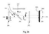
本発明について述べるために、図1に示されるようなWGPベースのLCoSマイクロディスプレイ・システムの1つの色チャネルから選択された光学機器が、さらに詳細に議論される。図2aおよび2bを参照すると、これらの光学機器は、前偏光子200、WGP201、トリム・リターダ202、VANモードLCoSパネル203、およびクリーンアップ偏光子204を含むサブシステムを形成する。
To describe the present invention, an optical instrument selected from one color channel of a WGP-based LCoS microdisplay system as shown in FIG. 1 will be discussed in further detail. Referring to FIGS. 2 a and 2 b, these optical instruments form a subsystem that includes a
前偏光子200は、P偏光(たとえば、水平両側矢印として示されている)を透過させるように方位づけされた偏光子である。一実施形態によれば、前偏光子は、グリッド・ベースの(反射)偏光子(たとえば、アルミニウム・ワイヤグリッド)または規則的な二色シート(吸収)偏光子のほぼ平行な要素の1つまたは複数のステージを含む。
WGP201は、当業者には周知であるように、透明基板の上に配置された複数の平行ミクロワイヤから形成された偏光子である。WGP201は、その透過軸が前偏光子201の透過軸にほぼ平行であり、かつミクロワイヤがy軸に平行に位置合わせされるように(すなわち、やはりP偏光のみを透過させるように)方位づけされる。通常、ワイヤは、WGP基板の背面上に配置され(前偏光子201から離れて)、それにより、直線偏光は、基板の熱および/または機械応力誘起複屈折によって受ける影響が小さくなる。そのようなWGP構成の第2の利点は、投影経路の光学要素の非点収差およびコマ収差を低減することである。
しかし、WGP201は、入射円錐束の中心光線に関して垂直入射に方位づけされない。むしろ、WGP201は、z軸に対して約45°だけ傾斜される。より具体的には、WGPは、XY平面に平行である初期位置合わせから+y軸の回りに+45°に回転される(または、単にz軸に対して+45°に傾斜される)。これは、右手XYZ座標系(RF−XYZ)でのオイラー角回転の慣例に準拠する。図2aおよび2bに示されるように垂直外入射において使用されるとき、WGP201は、透過直線偏光(たとえば、P偏光)が入射平面(P面)に含まれる場合、高偏光コントラスト・モードにおいて動作する。再び図2aおよび2bを参照すると、この高コントラスト構成は、マイクロワイヤがS面に平行(中心光線に関して入射平面に直交する)に方位づけされることを必要とする。光学システムの輝度とアパーチャとの間の兼ね合いのために(「エテンデュ」)、サブシステムは、各光学要素について中程度の数のアパーチャを使用することを必要とする。f/2.4システムで十分に機能するように光学要素を構成することが一般的である(大気入射において約±12°)。この場合、偏光のPおよびS面は、各局所WGP要素に対する円錐束の中心光線(これ以後の主光線と呼ぶ)の直線偏光を指す。
However,
トリム・リターダ202は補償要素であり、上記で議論されたように、マイクロディスプレイ・システムのコントラスト性能を向上させるために使用される。トリム・リターダ202は、Aプレート成分、ならびに任意選択でCプレート成分および/またはOプレート成分を含む。より具体的には、トリム・リターダ202は、LCoS 204の面内リターダンスより高いAプレート・リターダンスを提供する。その結果、トリム・リターダ202は、SA 230が非交差方式で隣接象限(すなわち、RF−XYZ座標系に関して第3象限)において方位づけされるようにオーバークロックされる。表1によれば、中程度に高いトリム・リターダ・リターダンスおよびかなり低いVAN−LCoSパネル・リターダンスでは、SA 230の位置は、通常30°未満であり、最も近い「S」軸または「P」軸から15°未満であることがさらにより好ましい。
The
トリム・リターダは、当技術分野において周知である。トリム・リターダを形成するために使用される材料のいくつかの例には、2軸または1軸の負の複屈折層を形成するように1つまたは2つの軸において伸張されている等方性ポリマー、酢酸セルロースなどの2軸有機フォイル、ディスコティック・フィルム、複屈折結晶、無機薄膜、ひずみらせん強誘電液晶ポリマー、および/またはポリマー・ホストに架橋された液晶混合物(LCP)がある。後者は、リターダンスを対象とする信頼性、一様性、および容易さについて非常に多面的であり、さらに、−Cプレート機能を提供するように無機薄膜と統合されることが実証されている。結果的な完全機能トリム・リターダは、優れたコントラスト補償ならびに環境安定性を提供することがさらに実証されている。 Trim retarders are well known in the art. Some examples of materials used to form trim retarders include isotropic stretches in one or two axes to form a biaxial or uniaxial negative birefringent layer There are polymers, biaxial organic foils such as cellulose acetate, discotic films, birefringent crystals, inorganic thin films, strained helical ferroelectric liquid crystal polymers, and / or liquid crystal mixtures (LCP) crosslinked to polymer hosts. The latter is very versatile in terms of reliability, uniformity, and ease for retardance, and has been demonstrated to be integrated with inorganic thin films to provide -C plate functionality. . The resulting fully functional trim retarder is further demonstrated to provide excellent contrast compensation as well as environmental stability.
VAN−LCoSパネル203は、当技術分野において周知であるように、垂直配向ネマチック・モード液晶オン・シリコン・パネルである。パネル203は、不透明基板203aおよび切替え可能液晶層203bを含むように示されている。カバー・ガラスおよび金属反射器は、示されていない。LCoSパネル203は、遅軸(SA)220がRH−XYZ座標系の第4象限に位置し、一方、第1パス(RH−XYZ)の観測者に入射するビームを見る状態で方位づけされている。VAN−LCoSパネルのSA220の記述において、極角が+z軸に向かって傾斜している(正の傾斜)SA220の方位角方位を参照する。VAN−LCoSパネルの速軸(FA)221は、SA方位に直交する(すなわち、SAに対して±90°の方位角ずれ)。FA221は、第1象限に位置し、x軸から45°の方位角にある。
The VAN-
VAN−LCoS203は、縦向きモードにおいて位置合わせされて示されている。より具体的には、矩形(たとえば、4:3または16.9のアスペクト比)ディスプレイ・ユニットは、最長寸法がWGPワイヤに平行に位置合わせされるように方位づけされている。縦向きモードを使用する利点は、傾斜WGPの寸法が、非傾斜WGPに対して〜1.41倍(すなわち、1/cos(45°))に増大されなければならないことである。したがって、垂直入射におけるWGPの16/9アスペクト比は、VAN−LCoSについて横向きモードが選択される場合の〜2.51ではなく、〜1.26になる。ほぼ1のアスペクト比は、高熱および高フラックス条件におけるWGPの湾曲が最小限に抑えられることを保証する。当然、横向きモードにおいて位置合わせされたVAN−LCoS203も可能である。
VAN-
クリーンアップ偏光子204は、S偏光(たとえば、図2aの垂直両側矢印および図2bの点で表される)を透過させるように方位づけされた偏光子である。前偏光子200およびクリーンアップ偏光子204は共に、主光線の伝播方向に対して同様に配置され、傾斜していない。一実施形態によれば、クリーンアップ偏光子204は、ほぼ平行な吸収偏光子要素の1つまたは複数のステージを含む。
動作時、先行ステージ照明(図示せず)から出力された無偏光または部分偏光240が、P偏光241を得るように前偏光子200を通過する。光は、WGP201を透過し、偏光消光比は改善される。トリム・リターダ202は、入射P偏光ビーム242を事前調整し、楕円出力を創出する。理想的には、ダーク(オフ)状態にあるLCoSパネル204に入射する偏光の楕円率は、残留パネル・リターダンスによって無効になる。したがって、反射光は、VAN−LCoSパネル203およびトリム・リターダ202を通る2重パスを完了した後、依然としてP偏光である。しかし、所与の円錐束と、トリム・リターダおよびVAN−LCoSパネル・リターダンスならびに軸方位の両方のある程度の空間変化とについて、出て行く光は、ある程度の楕円率243を累積している。わずかに楕円の偏光243は、WGP201によって分析される。より具体的には、楕円偏光のS偏光成分244は、WGP201のワイヤ側面によって直交経路212に偏向される。この成分は、「S漏れ」と呼ばれ、クリーンアップ偏光子204を通過する。漏れは、投影レンズ(図示せず)によってスクリーン(図示せず)に中継され、順次コントラストの低質化に寄与する。WGP201によって透過された残りのP偏向成分245は、光路213を介して照明システムに再び注入され、最終的には失われる。
In operation, unpolarized or partially
図2cおよび2dを参照すると、WGPベースのLCoSマイクロディスプレイ・システムの他の色チャネルから選択された光学機器が示されている。これらの光学機器は、前偏光子300、WGP301、トリム・リターダ302、VANモードLCoSパネル303、およびクリーンアップ偏光子304を含むサブシステムを形成する。
Referring to FIGS. 2c and 2d, an optical instrument selected from other color channels of a WGP-based LCoS microdisplay system is shown. These optical instruments form a subsystem that includes a
前偏光子300は、P偏光(たとえば、水平の両側矢印として示されている)を透過させるように方位づけされた偏光子である。一実施形態によれば、前偏光子は、グリッド・ベースの(反射型)偏光子(たとえば、アルミニウム・ワイヤグリッド)または規則的な二色シート(吸収型)偏光子のほぼ平行な要素の1つまたは複数のステージを含む。
The
WGP301は、当業者には周知であるように、透明基板の上に配置された複数の平行ミクロワイヤから形成された偏光子である。WGP301は、その透過軸が前偏光子301の透過軸にほぼ平行であり、また、ミクロワイヤがy軸に平行に位置合わせされるように(すなわち、やはりP偏光のみを透過させるように)方位づけされる。通常、ワイヤは、WGP基板の背面の上に配置され(前偏光子301から離れて)、それにより、直線偏光は、基板の熱および/あまたは機械応力誘起複屈折によって受ける影響が小さくなる。そのようなWGP構成の第2の利点は、投影経路の光学要素の非点収差およびコマ収差を低減することである。
The
しかし、WGP301は、入射円錐束の中心光線に関して垂直入射に方位づけされない。むしろ、WGP301は、z軸に対して約45°だけ傾斜される。より具体的には、WGPは、XY面に平行な初期位置合わせから+y軸の回りに−45°に回転される(または、単にz軸に対して−45°に回転される)。これは、右手XYZ座標系(RH−XYZ)でのオイラー角回転の慣例に準拠する。図2cおよび2dに示されるように垂直外入射において使用されるとき、WGP301は、透過直線偏光(たとえば、P偏光)が入射平面(P面)に含まれる場合、高偏光コントラスト・モードにおいて動作する。再び図2cおよび2dを参照すると、この高コントラスト構成は、ミクロワイヤがS面(中心光線に対して入射平面に直交する)に平行に方位づけされることを必要とする。光学システムの輝度とアパーチャとの兼ね合いのために(「エテンデュ」)、サブシステムは、各光学要素について中程度の数のアパーチャを使用することを必要とする。f/2.4システムで十分に機能するように光学要素を構成することが一般的である(大気入射において約±12°)。この場合、偏光のP面およびS面は、各局所WGP要素に対する円錐束の中心光線(これ以後主光線と呼ぶ)の直線偏光を指す。
However,
トリム・リターダ302は補償要素であり、上記で議論されたように、マイクロディスプレイ・システムのコントラスト性能レベルを向上させるために使用される。トリム・リターダ302は、Aプレート成分、ならびに任意選択でCプレート成分および/またはOプレート成分を含む。より具体的には、トリム・リターダ302は、LCoS303の面内リターダンスより高いAプレート・リターダンスを提供する。その結果、トリム・リターダ302は、SA330が非交差方式で隣接象限(すなわち、RH−XYZ座標系に関して第3象限)において方位づけされるようにオーバークロックされる。表1によれば、中程度に高いトリム・リターダ・リターダンスおよびかなり低いVAN−LCoSパネル・リターダンスでは、SA330の位置は、通常30°未満であり、最も近い「S」軸または「P」軸から15°未満であることがさらにより好ましい。
The
トリム・リターダは、当技術分野において周知である。トリム・リターダを形成するために使用される材料のいくつかの例には、2軸または1軸の負の複屈折層を形成するように1つまたは2つの軸において伸張されている等方性ポリマー、酢酸セルロースなどの2軸有機フォイル、ディスコティック・フィルム、複屈折結晶、無機薄膜、ひずみらせん強誘電液晶ポリマー、および/またはポリマー・ホストに架橋された液晶混合物(LCP)がある。後者は、リターダンスを対象とする信頼性、一様性、および容易さについて非常に多面的であり、さらに、−Cプレート機能を提供するように無機薄膜に統合されることが実証されている。結果的な完全機能トリム・リターダは、優れたコントラスト補償ならびに環境安定性を提供することがさらに実証されている。 Trim retarders are well known in the art. Some examples of materials used to form trim retarders include isotropic stretches in one or two axes to form a biaxial or uniaxial negative birefringent layer There are polymers, biaxial organic foils such as cellulose acetate, discotic films, birefringent crystals, inorganic thin films, strained helical ferroelectric liquid crystal polymers, and / or liquid crystal mixtures (LCP) crosslinked to polymer hosts. The latter is very versatile in terms of reliability, uniformity, and ease for retardance, and has been demonstrated to be integrated into inorganic thin films to provide -C plate functionality. . The resulting fully functional trim retarder is further demonstrated to provide excellent contrast compensation as well as environmental stability.
VAN−LCoSパネル303は、当技術分野において周知であるように、垂直配向ネマチック・モード液晶オン・シリコン・パネルである。パネル303は、不透明基板303aおよび切替え可能液晶層303bを含むように示されている。カバー・ガラスおよび金属反射器は、示されていない。LCoSパネル303は、遅軸(SA)320がRH−XYZ座標系の第4象限に位置し、一方、第1パス(RH−XYZ)の観測者に入射するビームを見る状態で方位づけされている。VAN−LCoSパネルのSA320の記述において、極角が+z軸に向かって傾斜している(正の傾斜)SA320の方位角方位を参照する。VAN−LCoSパネルの速軸(FA)321は、SA方位に直交する(すなわち、SAに対して±90°の方位角のずれ)。FA321は第1象限に位置し、x軸から45°の方位角にある。
The VAN-
VAN−LCoS303は、縦向きモードにおいて位置合わせされて示されている。より具体的には、矩形(たとえば、4:3または16:9のアスペクト比)のディスプレイ・ユニットは、最長寸法がWGPワイヤに平行に位置合わせされるように方位づけされている。縦向きモードを使用する利点は、傾斜WGPの寸法が、非傾斜WGPに対して〜1.41倍(すなわち、1/cos(45°))に増大されなければならないことである。したがって、垂直入射におけるWGPの16/9アスペクト比は、VAN−LCoSについて横向きモードが選択される場合の〜2.51ではなく、〜1.26になる。ほぼ1のアスペクト比は、高熱および高フラックス条件におけるWGPの湾曲が最小限に抑えられることを保証する。当然、横向きモードにおいて位置合わせされたVAN−LCoS303も可能である。
VAN-
クリーンアップ偏光子304は、S偏光(たとえば、図2cの垂直両側矢印および図2dの点で表される)を透過させるように方位づけされた偏光子である。前偏光子300およびクリーンアップ偏光子304は共に、主光線の伝播方向に対して同様に配置され、傾斜していない。一実施形態によれば、クリーンアップ偏光子304は、ほぼ平行の吸収偏光子要素の1つまたは複数のステージを含む。
動作時、先行ステージ照明(図示せず)から出力された無偏光または部分偏光340は、P偏光341を得るように前偏光子300を通過する。光はWGP301を透過し、偏光消光比は改善される。トリム・リターダ302は、入射P偏光ビーム342を事前調節し、楕円出力を創出する。理想的には、ダーク(オフ)状態にあるLCoSパネル303に入射する偏光の楕円率は、残留パネル・リターダンスによって無効になる。したがって、反射光は、VAN−LCoSパネル303およびトリム・リターダ302を通る2重パスを完了した後、依然としてP偏光である。しかし、所与の円錐束と、トリム・リターダおよびVAN−LCoSパネル・リターダンスならびに軸方位の両方のある程度の空間変化とについて、出て行く光は、ある程度の楕円率343を累積している。わずかに楕円の偏光343は、WGP301によって分析される。より具体的には、楕円偏光のS偏光成分344は、WGP301のワイヤ側面によって直交経路312に偏向される。この成分は、「S漏れ」と呼ばれ、クリーンアップ偏光子304を通過する。漏れは、投影レンズ(図示せず)によってスクリーン(図示せず)に中継され、順次コントラストの低質化に寄与する。WGP301によって透過された残りのP偏光成分345は、光路313を介して照明システムに再び注入され、最終的には失われる。
In operation, unpolarized or partially
図2aおよび2bに示されるWGP201は、z軸に対して+45°に傾斜しており、これは、図1に示されたLCoS投影システムの赤および青の色チャネルにおいて使用される方位と同じであり(すなわち、13、15と同様)、一方、図2cおよび2dに示されるWGP301は、z軸に対して−45°に傾斜しており、これは、緑色チャネルにおいて使用される方位と同じである(すなわち、14と同様)ことに留意されたい。より具体的には、第1WGP201は、第2WGP301の鏡像である。たとえば図1に示されるように、図2aおよび2cに示されるサブシステムが同じLCoS投影システムにおいて使用されるとき、トリム・リターダ202および302は、同一に方位づけされる、または方位づけされない。理想的には、同じトリム・リターダは、区別不可能な全コントラスト性能を有するWGPの2つの異なる方位について所与のLCoSパネルに有用である。
The
表2は、λ=550nmにおいて2nm/250nm Aプレート/CプレートVAN−LCoSパネルへのカスケードとしてモデリングされた完全機能Aプレート/−Cプレート・トリム・リターダ(TR)のシミュレーションのデバイス・パラメータ、想定、および性能パラメータを示す。 Table 2 shows the device parameters and assumptions for a full-function A-plate / -C-plate trim retarder (TR) simulation modeled as a cascade to 2 nm / 250 nm A-plate / C-plate VAN-LCoS panels at λ = 550 nm And performance parameters.
10,000:1のシステム・ベースライン・コントラストでは、2重パスTR/LCoSおよびTR反射直交偏光漏れ光(S漏れ)のインコヒーレント和は、λ=550nmにおいて6,700:1でモデリングされている。図3を参照すると、ビューイング・マップ(a)は、LCoS光オフ状態についてシミュレーションした2重パスTR/LCoS S漏れ透過を示し、一方、ビューイング・マップ(b)は、トリム・リターダ補償器のみの反射S漏れを示す。LH−XYZ座標系が使用されている。明らかに、パネルは、円錐束の各光線角度について一様で低レベルの漏れ光強度で十分に補償されている。 For a system baseline contrast of 10,000: 1, the incoherent sum of double pass TR / LCoS and TR reflected orthogonal polarization leakage light (S leakage) is modeled at 6,700: 1 at λ = 550 nm. Yes. Referring to FIG. 3, viewing map (a) shows a simulated dual path TR / LCoS S leakage transmission for LCoS optical off state, while viewing map (b) shows a trim retarder compensator. Only reflection S leakage is shown. The LH-XYZ coordinate system is used. Clearly, the panel is well compensated with a uniform and low level of leakage light intensity for each ray angle of the cone bundle.
システム・ベースライン・コントラストは、パネルが高品質ミラーによって置き換えられ、TRが通常の位置から取り除かれるときの光学システムの円錐加重明所視コントラスト比である。このベースラインの量は、WGPを含めて、交差偏光子の軸はずれ漏れ光を測定する。前偏光子、WGP、およびクリーンアップ偏光子の偏光コントラストは、発表されたデータから得られる。WPGがビーム分割デバイスとしてのみ使用され、前偏光子およびクリーンアップ偏光子の両方が二色シートで作成されると想定すると、TRに入射する光の偏光コントラストは、WGP透過偏光コントラストと二色透過偏光コントラストの積:450×1000によってほぼ与えられる。戻りパスにおいて、WGP反射は、偏光コントラストにおいて著しくより不十分であり、交差検光子について30×1000の偏光コントラストを与える。これらの2つの偏光消光比(偏光コントラストの逆数)は、モデルの入力偏光子および出力検光子のジョーンズ・ベクトルとして使用される。したがって、交差偏光子の軸はずれ効果は、システム・ベースライン・コントラストによって考慮される。 System baseline contrast is the cone-weighted photopic contrast ratio of the optical system when the panel is replaced by a high quality mirror and TR is removed from its normal position. This baseline amount measures the off-axis leakage light of the crossed polarizer, including WGP. The polarization contrast of the prepolarizer, WGP, and cleanup polarizer is obtained from the published data. Assuming that WPG is used only as a beam splitting device and both the pre-polarizer and the clean-up polarizer are made of dichroic sheets, the polarization contrast of the light incident on TR is the WGP transmissive polarization contrast and dichroic transmission. Polarization contrast product: approximately given by 450 × 1000. In the return pass, WGP reflection is significantly less in polarization contrast, giving a 30 × 1000 polarization contrast for the cross analyzer. These two polarization extinction ratios (reciprocal of polarization contrast) are used as Jones vectors for the model input polarizer and output analyzer. Therefore, the off-axis effect of crossed polarizers is taken into account by the system baseline contrast.
このシミュレーション・モデルでは、全システム・コントラストは、TRの遅軸の方位に依存しない。実際、数値結果は、様々なTR方位について<<1%のコントラスト比の変化を示す。数値モデルでは、LCoSパネルは、−45°LH−XYZシステムに方位づけされたSAを有し、一方、TRの公称SAは、−98.1°LH−XYZシステムに方位づけされる。近似分析式から得られるオーバークロック角度は、交差軸構成から±36.7°の方位角のずれ、またはこれらの2つの位置のさらに180°のずれである。数値モデルの4つのTR方位のいずれも、6,700:1の公称コントラスト比から有意な差を生成せず、10,000:1のシステム・ベースライン・コントラストを想定する。 In this simulation model, the overall system contrast does not depend on the TR slow axis orientation . In fact, the numerical results show a contrast ratio change of << 1% for various TR orientations . In the numerical model, LCoS panel has an orientation pickled been SA to -45 ° LH-XYZ system, whereas the nominal SA of the TR is orientation pickled to -98.1 ° LH-XYZ system. The overclocking angle obtained from the approximate analytical equation is an azimuthal deviation of ± 36.7 ° from the cross axis configuration, or a further 180 ° deviation of these two positions. None of the four TR orientations in the numerical model produces a significant difference from the nominal contrast ratio of 6,700: 1, assuming a system baseline contrast of 10,000: 1.
しかし、システム・コントラストの実験測定値は、モデリングされたのと同じVAN−LCoSパネルSA方位について、いくつかの色帯域において30%程度の差分コントラスト比を提供することが判明している。実験コントラスト比は、赤、緑、および青の色チャネルについて表3にまとめられている。 However, experimental measurements of system contrast have been found to provide differential contrast ratios on the order of 30% in several color bands for the same VAN-LCoS panel SA orientation as modeled. Experimental contrast ratios are summarized in Table 3 for the red, green, and blue color channels.
実験セットアップのWGP構成は、図2cに示されたものと同様であり、WGPは、z軸に対して−45°に傾斜していた。より具体的には、WGPは、z軸に対して−45°に傾斜し、パネルのSAは、LH−XYZ座標系に対して−45°に方位づけされた(すなわち、第4象限にあった)。540と名称付けされているこの構成は、図5cにおいて明確に示されている。546、547、548、および549と名称付けされている4つの可能なTR SA方位は、±オーバークロック角度およびその±180°の変化を使用して見つけられた。SA方位548および549は第1象限に位置し、一方、SA方位546および547は第3象限に位置する。実際の方位角オーバークロック角度は、各色帯域におけるTRおよびVAN−LCoSパネルの正確なAプレート・リターダンスに依存する。
The experimental setup WGP configuration was similar to that shown in FIG. 2c, with the WGP tilted to −45 ° with respect to the z-axis. More specifically, WGP is tilted to −45 ° with respect to the z-axis, and the panel SA is oriented at −45 ° with respect to the LH-XYZ coordinate system (ie, in the fourth quadrant). ) This configuration, labeled 540, is clearly shown in FIG. Four possible TR SA orientations , named 546, 547, 548, and 549, were found using the ± overclock angle and its ± 180 ° change.
実験コントラスト比は、明所視加重オン段階強度およびオフ状態強度の値を比率で表すことによって得られた。各色帯域の波長領域は、表3に与えられている。測定システム・ベースライン値は、収束f/2.4光円錐について、赤、緑、および青の波長帯域においてそれぞれ12,000:1、10,000:1、および6,000:1であった。再び表3を参照すると、最適システム・コントラスト比は、青、緑、および赤の波長帯域において、それぞれほぼ4,500、5,900、および7,900である。この最適方位は、第3象限に位置するTR SA547に対応し、LH−XYZ座標系に対して180°と255°の方位角の間に位置する。最悪TR SA方位と最適TR SA方位とを比較することによる利得は、青、緑、および赤の波長帯域において、それぞれ約35%、20%、および15%である。 The experimental contrast ratio was obtained by expressing the photopic weighted on-stage intensity and off-state intensity values as a ratio. The wavelength regions for each color band are given in Table 3. Measurement system baseline values were 12,000: 1, 10,000: 1, and 6,000: 1 in the red, green, and blue wavelength bands, respectively, for the convergent f / 2.4 light cone. . Referring again to Table 3, the optimal system contrast ratio is approximately 4,500, 5,900, and 7,900, respectively, in the blue, green, and red wavelength bands. This optimal orientation corresponds to TR SA547 located in the third quadrant and is located between 180 ° and 255 ° azimuth with respect to the LH-XYZ coordinate system. The gain from comparing the worst TR SA orientation with the optimal TR SA orientation is about 35%, 20%, and 15% in the blue, green, and red wavelength bands, respectively.
ここで使用される方位角(実験モデルおよび数値モデル)は、RH−XYZ座標系を基準とする。デバイス・モデルが指定されるとき、RH−XYZ座標系は、入射を基準とする。透過場を見るとき、RH−XYZ座標系は、透過ビームを基準とする。反射場または2重パス透過場を見るとき、RH−XYZ座標系は、戻りビームを基準とする。この慣例の結果として、透過側および入射側の座標セットは、互いに一貫しているが、反射側の座標セットは、入射座標セットに対して左右鏡の特性を有する。楕円偏光子およびリターダの記述において、楕円固有偏光の符号は、入射、透過、および反射の側において一貫して使用される。 The azimuth angle (experimental model and numerical model) used here is based on the RH-XYZ coordinate system. When a device model is specified, the RH-XYZ coordinate system is referenced to incidence. When viewing the transmitted field, the RH-XYZ coordinate system is referenced to the transmitted beam. When looking at the reflected or double pass transmitted field, the RH-XYZ coordinate system is referenced to the return beam. As a result of this convention, the transmission side and incident side coordinate sets are consistent with each other, while the reflective side coordinate sets have left-right mirror characteristics with respect to the incident coordinate sets. In the description of elliptical polarizers and retarders, the sign of elliptical intrinsic polarization is consistently used on the incident, transmission, and reflection sides.
RH−XYZ座標系は、図4aに示されている。座標軸は、入射ビームを正面から見ることに関してオイラー角(1軸媒体では2つの角度、および2軸媒体では3つの角度)を指定したときのRH−XYZを表す。各1軸層の極角および方位角は、(θc,φc)によって表される。反射(または2重パス透過)デバイスを入射側から見るとき、RH−XYZ系は、X軸の方向を反対にすることによって維持される。反射を見るためのRH−XYZ座標セットは、入射ビームを基準とするLH−XYZ座標セットと等しい(すなわち、入射の背面を見る)。これは、図4bに示されている。RH−XYZ座標系およびLH−XYZ座標系の両方において(共に入射の基準とされるので世界的定義)、方位角は、正のx軸から半時計回り(CCW)の回転について正と定義される。この軸方位は、たとえば、リターダの高速/遅軸を述べるために使用される。光円錐において視平面を指定するために、透過視平面は、入射平面に対して位置合わせされる。しかし、反射(または2重パス透過)システムでは、視平面は、入射平面から180°ずれている(360°の方位角平面領域および0から90°の極角領域について)。 The RH-XYZ coordinate system is shown in FIG. 4a. The coordinate axes represent RH-XYZ when the Euler angles (two angles for uniaxial media and three angles for biaxial media) are specified for viewing the incident beam from the front. The polar angle and azimuth angle of each uniaxial layer are represented by (θ c , φ c ). When viewing a reflective (or double pass transmissive) device from the incident side, the RH-XYZ system is maintained by reversing the direction of the X axis. The RH-XYZ coordinate set for viewing the reflection is equal to the LH-XYZ coordinate set relative to the incident beam (ie, looking at the back of the incident). This is shown in FIG. 4b. In both the RH-XYZ coordinate system and the LH-XYZ coordinate system (both defined globally because they are the basis for incidence), the azimuth is defined as positive for counterclockwise (CCW) rotation from the positive x axis. The This axial orientation is used, for example, to describe the fast / slow axis of the retarder. In order to specify a viewing plane in the light cone, the transmission viewing plane is aligned with respect to the incident plane. However, in a reflective (or double pass transmission) system, the viewing plane is 180 ° off the incidence plane (for 360 ° azimuthal plane region and 0 to 90 ° polar angle region).
XYZ座標系の慣例は確立されているので、図2a〜dに示されたサブシステムにおけるTRおよびLCoSのすべての可能な構成が、さらに分析される。図5a〜dを参照すると、WGP501がz軸に対して−45°に方位づけされるときのTRおよびLCoSの方位の可能な構成が示されている。より具体的には、図5aは、第1LCoSパネル503の方位について、TR502の4つの可能なSA方位(506、507、508、および509)を含む第1構成500を示し、LCoS SA 504は第3象限に位置し、速軸505にほぼ直交する。図5bは、第2LCoSパネル523の方位について、TR522の4つの可能なSA方位(526、527、528、および529)を含む第2構成520を示し、LCoS SA 524は第1象限に位置し、第1軸525にほぼ直交する。図5cは、第3LCoSパネル543の方位について、TR542の4つの可能なSA方位(546、547、548、および549)を含む第3構成540を示し、LCoS SA 544は第4象限に位置し、速軸545にほぼ直交する。図5dは、第4LCoSパネル563の方位について、TR562の4つの可能なSA方位(566、567、568、および569)を含む第4構成560を示し、LCoS SA 564は第2象限に位置し、速軸565にほぼ直交する。これらの構成500、520、540、および560は、LH−XYZ座標系を基準とする。パネルのSA504、524、544、および564は、システムのS偏光方向およびP偏光方向をほぼ二等分すると想定される(たとえば、二等分線の±10°内において)。
Since the convention of the XYZ coordinate system is established, all possible configurations of TR and LCoS in the subsystems shown in FIGS. Referring to FIGS. 5a-d, possible configurations of TR and LCoS orientations when
図6a〜dを参照すると、WGP601がz軸に対して+45°に方位づけされているときの4つの可能なLCoSパネルSA方位、および16つの可能なTR SA方位が示されている。より具体的には、図6aは、第3LCoSパネル603の方位について、TR602の4つの可能なSA方位(606、607、608、および609)を含む第1構成600を示し、LCoS SA 604は第4象限にあり、速軸605にほぼ直交する。図6bは、第4LCoSパネル623の方位について、TR622の4つの可能なSA方位(626、627、628、および629)を含む第2構成620を示し、LCoS SA 624は第2象限にあり、速軸625にほぼ直交する。図6cは、第1LCoSパネル634の方位について、TR642の4つの可能なSA方位(646、647、648、および649)を含む第3構成640を示し、LCoS SA 644は第3象限にあり、速軸645にほぼ直交する。図6dは、第2LOCSパネル663の方位について、TR662の4つの可能なSA方位(666、667、668、および669)を含む第4構成660を示し、LCoS SA 664は第1象限にあり、速軸665にほぼ直交する。600、620、640、および660と呼ばれる4つの可能な光学システム構成は、それぞれ、構成500、520、540、および560の鏡像(y軸について)である。CCW正の方位角の慣例でのLH−XYZ座標系が、TRおよびLCoSの遅軸の方位を表すために採用されたが、実際に示された方位は、Oプレート複屈折媒体の光学軸(LCoSおよび可能であればTRデバイスにおける)が、入射光に対して+z方向に傾斜されることを意味する。
Referring to FIGS. 6a-d, there are shown four possible LCoS panel SA orientations and 16 possible TR SA orientations when
数値モデルは、傾斜WGPの役割をモデルに組み込まない場合、異なるTRクロック角度について大きく異なるコントラスト・レベルを予測しないので、実験データは、システムの性能を定量化するために使用されてきた。実験は、f/2.4収束光円錐を使用した。3つの要素(WGP、TR、およびLCoS)の方位を含む32の可能な構成があるが、図5および6に示された構成間の鏡特性は、16の非固有構成を排除するために使用された。さらに、トリム・リターダ補償器の2つの変形形態が使用された。第1タイプのTRは、SA平面に沿って測定されるとき、入射角度(AOI)に対して正味線形リターダンスの非対称特性を有する。このタイプの特性は、たとえば、傾斜1軸Oプレートまたは傾斜2軸Oプレートによって与えることが可能である。第2タイプのTRは、SA平面に沿ってAOIに対して対称線形リターダンス特性を有する。非対称TRおよび対称TRのSAおよびFA平面正味線形リターダンス特性が、図7および8にそれぞれ示されている。図7を参照すると、非対称TRは、約5°のAOIにおいてピーク線形リターダンスを示す。一般に、非対称リターダは、非均一1軸Oプレート/−Cプレート・カスケードまたは均一傾斜2軸Oプレートとして傾斜構造を含む。図8を参照すると、対称TRの2軸特性は、垂直入射について鏡像化される。この実験データは、λ=450nmにおいてアクソメトリックス・アクソスキャン・ミュラー(Axometrics AxoScan Mueller)・マトリックス偏光計で収集された。この波長は、青帯域のほぼ中心にあり、表3に示されるように様々なTR方位のコントラスト比が劇的に異なることにより選択された。非対称および対称TRの例の単一パス透過リターダンス成分(すなわち、線形リターダンス、線形リターダ軸、および円形リターダンス)が、図9および10にそれぞれ示されている。垂直入射における非対称リターダのSA方位は、ビームを正面から見るとき、RH−XYZ座標系に対してほぼ−85°に位置合わせされている。垂直入射における対称リターダのSA方位は、ビームを正面から見るとき、RH−XYZ座標系に対して−65°にほぼ位置合わせされている。非対称TRは、すべての視方位角にわたって±20°のAOIまで著しい円形リターダンスを示さない。しかし、対称TRの例は、同じ視円錐にわたって、λ=450nmにおいて最高で7nmの円形リターダンスの大きさを示す。 Experimental data has been used to quantify system performance because numerical models do not predict significantly different contrast levels for different TR clock angles if the role of tilted WGP is not incorporated into the model. The experiment used an f / 2.4 converging light cone. Although there are 32 possible configurations involving the orientation of 3 elements (WGP, TR, and LCoS), the mirror properties between the configurations shown in FIGS. 5 and 6 are used to eliminate 16 non-unique configurations It was done. In addition, two variants of trim retarder compensator were used. The first type of TR has a net linear retardance asymmetric characteristic with respect to the angle of incidence (AOI) when measured along the SA plane. This type of characteristic can be provided, for example, by a tilted 1-axis O-plate or a tilted 2-axis O-plate. The second type TR has a symmetric linear retardance characteristic with respect to the AOI along the SA plane. The SA and FA planar net linear retardance characteristics of asymmetric TR and symmetric TR are shown in FIGS. 7 and 8, respectively. Referring to FIG. 7, the asymmetric TR exhibits a peak linear retardance at an AOI of about 5 °. In general, asymmetric retarders include tilt structures as non-uniform uniaxial O-plate / -C plate cascades or uniform tilted bi-axial O-plates. Referring to FIG. 8, the biaxial characteristics of the symmetric TR are mirrored for normal incidence. This experimental data was collected on an Axometrics AxoScan Mueller matrix polarimeter at λ = 450 nm. This wavelength was chosen at the approximate center of the blue band and the dramatically different contrast ratios for the various TR orientations as shown in Table 3. Example single pass transmission retardance components (ie, linear retardance, linear retarder axis, and circular retardance) for asymmetric and symmetric TR are shown in FIGS. 9 and 10, respectively. The SA orientation of the asymmetric retarder at normal incidence is aligned to approximately -85 ° with respect to the RH-XYZ coordinate system when viewing the beam from the front. The SA orientation of the symmetric retarder at normal incidence is approximately aligned to -65 ° with respect to the RH-XYZ coordinate system when viewing the beam from the front. The asymmetric TR does not show significant circular retardance up to ± 20 ° AOI across all viewing azimuth angles. However, the example of symmetric TR shows a circular retardance magnitude of up to 7 nm at λ = 450 nm over the same viewing cone.
実験のコントラスト結果は、PR−705スペクトル放射計で収集された。光オフ状態および光オン状態における強度は、青色帯域(λ=430nから490nm)において明所視的に加重された。VAN−LCoSパネルは、光オフ状態において駆動されなかった。これらの結果は、構成500、520、540、および560について表4a〜dにそれぞれ列挙されている。構成600、620、640、および660の実験結果は、光学構成における鏡対称性を考慮に入れて、それぞれ構成500、520、540、および560から導出された。
Experimental contrast results were collected on a PR-705 spectral radiometer. Intensities in the light-off and light-on states were photopically weighted in the blue band (λ = 430n to 490 nm). The VAN-LCoS panel was not driven in the light off state. These results are listed in Tables 4a-d for
これらの実験結果は、所与のLCoSパネル方位のTRの4つの可能な方位が等しいという一般的な考えを無効にする。異なる結果が、青帯域における各パネル方位、各TR方位、および各WGP方位について示されている。これらの結論は、可視波長領域のすべての色帯域に拡張することができる。 These experimental results negate the general idea that the four possible orientations of TR for a given LCoS panel orientation are equal. Different results are shown for each panel orientation , each TR orientation , and each WGP orientation in the blue band. These conclusions can be extended to all color bands in the visible wavelength region.
非対称TRを含むサブシステムについて測定されたコントラスト比を参照すると、WGPがどのように方位づけされているかに関係なく、各パネル方位について1つの最適TR方位が一般に存在する。各場合において、最適TR方位は、垂直入射におけるトリム・リターダの遅軸がシステムに入力される直線偏光に最も近くなるように位置合わせされる。この場合、遅軸方位は、RH−XYZ座標系において傾斜した正の1軸ディレクタおよびLH−XYZ座標系において傾斜した負の1軸ディレクタでの方位角を指す。 Referring to the contrast ratio measured for the sub-system including an asymmetric TR, regardless of WGP how are orientation pickled is, one of the optimal TR orientation for each panel orientation generally present. In each case, the optimal TR orientation is aligned so that the slow axis of the trim retarder at normal incidence is closest to the linear polarization input to the system. In this case, the slow axis azimuth refers to the azimuth angle at the positive uniaxial director inclined in the RH-XYZ coordinate system and the negative uniaxial director inclined in the LH-XYZ coordinate system.
トリム・リターダのAプレート・リターダンスが、LCoSパネルのAプレート・リターダンスより中程度に大きい場合、TRのSAは、光学システムへの入射直線偏光にほぼ平行である(たとえばここで示される光学セットアップではx軸の±30°内、またはより好ましくは±15°内)。各VAN−LCoSパネル方位について、入射偏光に最も近いSA方位を選択しているので、最適TR SA位置は、表6(a)に列挙されるように特定の1/8円内において選択される。 If the trim retarder's A-plate retardance is moderately greater than the LCoS panel's A-plate retardance, then the TR SA is approximately parallel to the linear polarization incident on the optical system (eg, the optical shown here). Set-up within ± 30 ° of x-axis, or more preferably within ± 15 °). For each VAN-LCoS panel orientation , the SA orientation closest to the incident polarization is selected, so the optimal TR SA position is selected within a specific 1/8 circle as listed in Table 6 (a). .
対称TRの場合、遅軸は、180°回転方位から容易には区別されない。青帯域における実験コントラスト結果は、垂直入射におけるTRのSAが入射直線偏光に最も近く位置合わせされるべきであることを示す。選択されたTR SA方位およびその180°回転バージョンは、測定雑音内においてコントラスト性能を与える。2つの最適TR SA位置は、表6(b)に列挙されるように特定の1/8円内において選択される。 In the case of symmetric TR, the slow axis is not easily distinguished from the 180 ° rotation orientation . Experimental contrast results in the blue band indicate that the TR SA at normal incidence should be aligned closest to the incident linear polarization. The selected TR SA orientation and its 180 ° rotated version give contrast performance within the measurement noise. The two optimal TR SA positions are selected within a specific 1/8 circle as listed in Table 6 (b).
2つのデバイスのアスペクト比に関係なく、トリム・リターダ補償器およびVAN−LCoSパネルの遅軸方位のみを参照することに留意されたい。各色チャネルにおける所与のWGP方位および非対称TRでは、いくつかのパネルSA位置について(たとえば、−45°WGP方位を有する構成560、および+45°方位を有する構成660)、ほぼ等しい最高コントラスト値を有する最高で3つのTR方位が存在する。3つのTR方位のいずれか1つを選択することが可能である。パネルSAの他の方位では、単一の最適TR SA方位のみが存在する可能性がある(たとえば、−45°WGP方位を有する構成520、および+45°WGP方位を有する構成620)。最適SA方位は、それぞれ表6aおよび6bにおいて概述されたように、対称TRについて1つの1/8円領域内、および対称TRについて2つの1/8円領域内にあり、投影システムにおけるWGPの方位およびLCoSパネルSAの方位に関係なく、ほぼ等しい像コントラスト性能を見込む。
Note that only the slow-axis orientation of the trim retarder compensator and VAN-LCoS panel is referred to, regardless of the aspect ratio of the two devices. For a given WGP orientation and asymmetric TR in each color channel, for some panel SA positions (eg,
VAN−LCoSパネルの公称SAは、±45°および±135°において名目的に固定されていた。実際には、この公称SA方位の小さい許容領域が存在する。許容度は、上述したVAN−LCoSパネル公称SA方位から通常±15°内、より好ましくは±10°内、さらにより好ましくは±5°内の逸脱である。所与の象限における意図したSP二等分線からのパネルSA方位のこれらの小さい方位角逸脱は、表6(a)および6(b)において報告された最適TR SA方位領域に影響を与えない。 The nominal SA for VAN-LCoS panels was fixed nominally at ± 45 ° and ± 135 °. In practice, there is an acceptable region with a small nominal SA orientation . The tolerance is usually a deviation within ± 15 °, more preferably within ± 10 °, and even more preferably within ± 5 ° from the nominal SA orientation of the VAN-LCoS panel described above. These small azimuthal deviations of the panel SA orientation from the intended SP bisector in a given quadrant do not affect the optimal TR SA orientation region reported in Tables 6 (a) and 6 (b). .
TRが非対称TRであるときのすべての4つのVAN−LCoSパネル方位のTR SA方位の最適領域が、図11a/b、12a/b、13a/b、および14a/bに示されている。各LCoS方位について、一般に、大域コントラスト最大値を提供する唯一のTR SA方位が存在する。陰影領域(すなわち、所定の1/8円内)におけるこの方位の選択は、両方のWGP方位についてLOCSパネルSA方位のいずれか1つを有するほぼ等しいコントラスト性能を見込む最適方位を提供する。 The optimum region of TR SA orientation for all four VAN-LCoS panel orientations when TR is asymmetric TR is shown in FIGS. 11a / b, 12a / b, 13a / b, and 14a / b. For each LCoS orientation there is generally a unique TR SA orientation that provides the global contrast maximum. Selection of this orientation in the shaded area (ie, within a predetermined 1/8 circle) provides an optimal orientation that allows for approximately equal contrast performance with either one of the LOCS panel SA orientations for both WGP orientations .
各光学構成における非対称トリム・リターダの唯一の最適方位は、y軸についてLCoSパネルSAの象限位置に鏡像化される象限に位置するSA方位角を有する。y軸は、2つのWGP方位(z軸に対して±45°傾斜)の回転軸でもある。最適TR SA方位は、LCoSパネルSAの象限位置に鏡像化される象限において、入射偏光軸に最も近い円の1/8内に含まれる。この観測は、最高で半波のTR Aプレート・リターダンスのすべての値について有効である。半波TR Aプレート値を超えると、遅軸および速軸の役割は切り替えられる。低い面内リターダンスを有するVAN−LCoSパネルを補償するために、λ=550nmを基準として、0nmから約4分の1の波、より好ましくは0nmから1/10の波、さらにより好ましくは1/50の波にわたるAプレート値を有するTRを使用することが一般的である。 The only optimal orientation of the asymmetric trim retarder in each optical configuration has an SA azimuth located in a quadrant that is mirrored to the quadrant location of the LCoS panel SA about the y-axis. The y-axis is also the rotation axis of two WGP orientations (tilt ± 45 ° with respect to the z-axis). The optimal TR SA orientation is contained within 1/8 of the circle closest to the incident polarization axis in the quadrant mirrored at the quadrant position of the LCoS panel SA. This observation is valid for all values of TRA plate retardance up to half-wave. When the half wave TRA plate value is exceeded, the roles of the slow axis and the fast axis are switched. To compensate for a VAN-LCoS panel with low in-plane retardance, λ = 550 nm as a reference, from 0 nm to about a quarter wave, more preferably from 0 nm to 1/10 wave, even more preferably 1 It is common to use TRs with A-plate values over / 50 waves.
トリム・リターダの非反射特性がデバイスの前面および背面から離れると十分に同様である場合、構成500および640について最適に方位された非対称トリム・リターダ(すなわち、パネル方位#1)は、トリム・リターダがx軸の回りに180°だけ回転される場合、構成540および600(すなわち、パネル方位#3)を最適に補償するように変換することが可能であり、またその反対も可能である。すなわち、マークされたSA位置は、x軸について鏡像化される。しかし、パネルの斜め傾斜の意味が反転されるので、正の傾斜(z軸に対して)に関するSA方位は、さらに180°の方位角のずれを有する。同様に、構成520および660(すなわち、パネル方位#2)ならびに構成560および620(すなわちパネル方位#4)の最適非対称TR方位は、x軸の回りの180°の回転によって鏡像化され、連結される。
If the non-reflective properties of the trim retarder are sufficiently similar away from the front and back of the device, the asymmetric trim retarder optimally oriented for
対称TRを有する最適TR SA方位のグラフ表示が、図15a/b、16a/b、17a/b、nおよび18a/bに与えられている。各LCoSパネルSA方位について、ほぼ等しいコントラスト性能の2つのTR SA方位がある。これらの2つの最適方位は、入射直線偏光にほぼ平行である。これらの2つの方位の領域は、入射直線偏光に最も近い陰影の付けられた1/8円としてマークされている。 A graphical representation of the optimal TR SA orientation with symmetric TR is given in FIGS. 15a / b, 16a / b, 17a / b, n and 18a / b. For each LCoS panel SA orientation, there are two TR SA orientations with approximately equal contrast performance. These two optimal orientations are approximately parallel to the incident linear polarization . These two orientation regions are marked as the shaded 1/8 circle closest to the incident linear polarization.
WGP方位の選択は、TRが対称TRであるとき、最適TR SA位置における絶対コントラスト数について差を生じることに留意されたい。たとえば、表4bおよび5dを参照すると、青帯域の実験コントラスト測定は、構成520について3500の最大値、構成660について4500の最大値を示し、共にパネル方位#2を使用する。比較すると、TRが非対称TRであるとき、比較的小さい差が存在する(すなわち、構成520および660についてそれぞれ4200と4300の間)。
Note that the selection of the WGP orientation makes a difference in the absolute contrast number at the optimal TR SA position when TR is symmetric TR. For example, referring to Tables 4b and 5d, blue band experimental contrast measurements show a maximum of 3500 for
トリム・リターダ方位を変化させることによるシステム・コントラストの実験観測差は、VAN−LCoSパネルおよびWGPをモデリングすることによってさらに調査された。 The experimental observation difference in system contrast by changing the trim retarder orientation was further investigated by modeling VAN-LCoS panels and WGP.
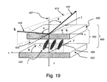
投影ディスプレイにおいて使用されるVAN−LCoSパネルは、斜め方位LCデバイス(すなわち、Oプレート構成)としてモデリングされた。図19は、斜め方位LCoSデバイスにおけるLCセル400の一例を示す。LC層401は、カバー・ガラス420とシリコン基板403との間に挟まれる。超大規模集積(VLSI)電子回路および光学品質反射電極(たとえば、アルミニウム・ミラー、図示せず)が、基板403の上面の上に製造される。ミラーにおける印加電圧が、LC分子404を駆動し、カバー・ガラス402の上の対向透明電極が、他の電気接点を提供する。光オフ状態において、長距離平均LCディレクタ405は、デバイスの法線(z方向)407からわずかに傾斜される。この極角θcは、方位角φcのデバイス平面上への投影を有する。方位角平面は、傾斜平面406でもある。極角θcは、+z軸に対して正の角度であり、0と90°の間の値に制限されることに留意されたい。LCディレクタの方位角φcは、360°の領域内において画定される。傾斜平面および極角は、図19において「RH−XYZ」座標系で示されている。角度(θc,φc)の対は、平均LCディレクタの方位を一意に指定する。LCoSデバイスは、ほぼ軸上円錐で照明される(すなわち、円錐軸は、デバイスの法線に垂直である)。入射平面410は、デバイス法線407に対して極角θに傾斜している波ベクトル408を含む。LCoSなどの反射デバイスでは、LH−XYZ座標系において視角を示すことが好都合である。入射波ベクトルは、409として反射される。この視平面(入射平面に対して180°方位角が異なる)により、LH−XYZ系のx軸を有する角度φvが生成される。同様に、角度(θ,φv)の対は、視位置を一意に指定する。
The VAN-LCoS panel used in the projection display was modeled as a diagonally oriented LC device (ie, an O-plate configuration). FIG. 19 shows an example of an
VAN−LCoSパネルにおいて使用されるLC混合物は、負の誘電非等方性を有する正の1軸材料である。これらのタイプのLC混合物のいくつかの例には、メルク(Merck)のMLC−6608およびMLC−6610がある。印加電場において、LCディレクタは、デバイス平面に向かって回転される。光オフ状態において、LCセルは、切替えに必要な閾値電圧以下において駆動され、または全く駆動されない。LCディレクタは、光オフ状態においてほぼホメオトロピックである。小さい事前傾斜角度が、LCディレクタの回位を回避し、フリンジ場の切替えによって受ける影響をより小さくし、および通常動作において切替え応答を高速化するために、5°と10°との間に通常設定される。VAN−LCoSの傾斜平面は、遅軸平面に対応する。VAN−+LCoSパネルのOプレート構造で、LC分子の正の傾斜を含む方位角が決定された。VAN−LCoSのLC事前傾斜は、セルの厚さにわたって均一であると想定された。透過デバイスでは、このOプレート構造は、視円錐全体(たとえば、最高で±30°の極角)にわたって有意な円形リターダンスを生成しない。しかし、均一なOプレート構造により、反射の際に測定可能な円形リターダンスが生じる。 The LC mixture used in VAN-LCoS panels is a positive uniaxial material with negative dielectric anisotropy. Some examples of these types of LC mixtures are Merck's MLC-6608 and MLC-6610. In the applied electric field, the LC director is rotated towards the device plane. In the light-off state, the LC cell is driven below the threshold voltage required for switching or not driven at all. The LC director is almost homeotropic in the light-off state. A small pre-tilt angle is usually between 5 ° and 10 ° in order to avoid LC director rotation, to be less affected by fringe field switching, and to speed up the switching response in normal operation. Is set. The inclined plane of VAN-LCoS corresponds to the slow axis plane. With the O plate structure of the VAN- + LCoS panel, the azimuth angle including the positive tilt of the LC molecules was determined. The LC pre-tilt of VAN-LCoS was assumed to be uniform across the cell thickness. In transmissive devices, this O-plate structure does not produce significant circular retardance over the entire viewing cone (eg, polar angle up to ± 30 °). However, the uniform O-plate structure produces a measurable circular retardance upon reflection.
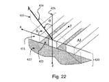
図20は、正の傾斜を有する遅軸方位を決定するためにモデリングされたVAN−LCoSパネルについてシミュレーションした反射リターダンス成分を示す。より具体的には、図20は、すべての方位角視平面について30°AOIにおけるVAN−LCoSのシミュレーションを示す。視平面が傾斜平面と一致するとき、観測者(または測定機器)は、最大線形リターダンスを認識するが、円形リターダンスは認識しない。これは、LCセルの遅軸を含む平面である。反対に、視平面が速軸平面と一致するとき(傾斜平面に直交)、観測者は、線形リターダンスにおいてディップを認識し、一方、円形リターダンスの大きさは最大である。円形リターダンスは、それぞれ、正および負の符号を割り当てられ、左手および右手の円形偏光に関連する。この慣例は、イェー(Yeh)ら、「Optics of liquid crystals displays」、John Wiley&Sons、ニュー・ヨークにおいて議論されている性質命名法に準拠する。プロットは、LCoS SA方位(z軸に対して正の極角を有するLCの傾斜平面)の[45°、135°、225°、315°]のLH−XYZについて±円形リターダンス符号の位置を示す。 FIG. 20 shows the reflected retardance component simulated for a VAN-LCoS panel modeled to determine the slow axis orientation with a positive slope. More specifically, FIG. 20 shows a VAN-LCoS simulation at 30 ° AOI for all azimuthal viewing planes. When the viewing plane coincides with the inclined plane, the observer (or measuring instrument) recognizes the maximum linear retardance but not the circular retardance. This is a plane including the slow axis of the LC cell. Conversely, when the viewing plane coincides with the fast axis plane (orthogonal to the tilted plane), the observer recognizes the dip in linear retardance, while the circular retardance has the largest magnitude. Circular retardance is assigned positive and negative signs, respectively, and is associated with circular polarization of the left hand and right hand. This convention follows the property nomenclature discussed in Yeh et al., “Optics of liquid crystals displays”, John Wiley & Sons, New York. The plot shows the position of ± circular retardance code for LH-XYZ [45 °, 135 °, 225 °, 315 °] in LCoS SA orientation (LC tilt plane with positive polar angle with respect to z-axis). Show.
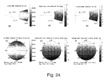
図21は、最高で±30°の極角の視円錐についてLCoSリターデーション成分を与える。これらのリターダンス成分である線形リターダンス、リターダンス軸、および円形リターダンスが、それぞれ(a)、(b)、および(c)に示されている。LCoSモデルにおけるLCディレクタは、135°(RH−XYZの慣例に関して)に位置し、したがって、SAは、北東/南西の線(LH−XYZ視円錐に関して)に沿って位置する。線形リターダンス・マップによってVAN−LCoS傾斜平面を決定することが可能であるが、円形リターダンス・マップが使用されない限り、LCの正対負の傾斜の意味を認識することは不可能である。円形リターダンスの大きさは、SA平面に沿ってほぼゼロである。直交方位角平面に沿って、円形リターダンスは、最大の大きさに達する。最大円形リターダンスの大きさの符号は、正のLCディレクタの傾斜(LH−XYZ座標系における回転)では、VAN−LCoS SA方位角から90度のCCW視方位角回転において正であり、90度のCW視方位角の回転において負である。約30°の軸はずれ照明において、円形リターダンスの大きさは、容易に測定することができる。このシミュレーションでは、VAN−LCoSは、λ=550nmにおいて2nm/250nmAプレート/Cプレートの4.5°の事前傾斜および線形リターダンス成分を有し、LCディレクタは、φc=135°に方位づけした正の傾斜を有する(RH−XYZ座標系)。コノスコープ円形リターダンス・マップは反射を見るように示されているので、遅軸は、45°の方位角に位置する(LH−XYZ座標系)。 FIG. 21 gives the LCoS retardation component for viewing cones with polar angles up to ± 30 °. These retardance components, linear retardance, retardance axis, and circular retardance are shown in (a), (b), and (c), respectively. The LC director in the LCoS model is located at 135 ° (with respect to the RH-XYZ convention), so SA is located along the northeast / southwest line (with respect to the LH-XYZ viewing cone). Although it is possible to determine the VAN-LCoS tilt plane by means of a linear retardance map, it is impossible to recognize the meaning of LC positive and negative tilt unless a circular retardance map is used. The magnitude of the circular retardance is almost zero along the SA plane. Along the orthogonal azimuth plane, the circular retardance reaches its maximum magnitude. The sign of the magnitude of the maximum circular retardance is positive in CCW viewing azimuth rotation of 90 degrees from VAN-LCoS SA azimuth at positive LC director tilt (rotation in LH-XYZ coordinate system), 90 degrees Is negative in the rotation of the CW viewing azimuth angle. In about 30 ° off-axis illumination, the magnitude of the circular retardance can be easily measured. In this simulation, VAN-LCoS has a 4.5 ° pre-tilt and linear retardance component of 2 nm / 250 nm A plate / C plate at λ = 550 nm, and the LC director oriented to φ c = 135 °. Has a positive slope (RH-XYZ coordinate system). Since the conoscopic circular retardance map is shown to see reflections, the slow axis is located at an azimuth of 45 ° (LH-XYZ coordinate system).
パネルの正味の反射リターダンス特性が極角および方位角の視角に対してプロットされるとき、明らかに、LCoSパネルの垂直入射に平行な単一対称軸が欠如している。この対称性の欠如は、少なくとも一部には、トリム・リターダの4つの可能なオーバークロック角度に対応する4つの局所的なコントラスト最大値が等しくないことが理由であると考えられる。 When the net reflection retardance characteristic of the panel is plotted against polar and azimuthal viewing angles, there is clearly a lack of a single symmetry axis parallel to the normal incidence of the LCoS panel. This lack of symmetry is believed to be due at least in part to the unequal four local contrast maxima corresponding to the four possible overclocking angles of the trim retarder.
上記で議論されたように、トリム・リターダおよびVAN−LCoSパネルを含む2ステージ・モデルは、トリム・リターダのSA方位に関する補償効率の依存性を予測しない(すなわち、4つの可能なオーバークロック角度は、ほぼ同じ補償を提供する)。さらに、モデルにおける入力偏光子および出力検光子は複屈折ではなかったが、適切な偏光消光比が含まれていた。高性能LCoSシステムでは、ワイヤグリッドPBSが、広範な波長帯域および広範な角度許容度を可能にするために使用される。損失に加えて(より低いスループット効率)、WGPの第2の望ましくない態様は、デバイスの位相リターダンスである。 As discussed above, the two-stage model, including trim retarder and VAN-LCoS panel, does not predict the dependency of compensation efficiency on trim retarder SA orientation (ie, the four possible overclocking angles are Provide nearly the same compensation). Furthermore, the input polarizer and output analyzer in the model were not birefringent, but included an appropriate polarization extinction ratio. In high performance LCoS systems, wire grid PBS is used to allow a wide wavelength band and wide angular tolerance. In addition to loss (lower throughput efficiency), the second undesirable aspect of WGP is device phase retardance.
実際、WGPは、有効媒体理論(EMT)屈折率楕円体を有する複屈折デバイスである(しかし、主な機能は、依然としてビーム・スプリッタおよび偏光子の1つである)。WGP屈折率楕円体は、投影応用分野では、公称システムXY平面から傾斜される。明らかに、WGPは、VAN−LCoSパネルの残留リターダンス補償に影響を与える複屈折特性を有する。垂直入射において、非常に高い消光比は、複屈折効果を排除するはずである。しかし、円錐応用分野では、特に反射の際に、スキュー光線効果が、TR/LCoS対の固有コントラストの達成において限定因子となる。 In fact, WGP is a birefringent device with an effective medium theory (EMT) index ellipsoid (but the main function is still one of a beam splitter and a polarizer). The WGP index ellipsoid is tilted from the nominal system XY plane for projection applications. Apparently, WGP has birefringence properties that affect the residual retardance compensation of VAN-LCoS panels. At normal incidence, a very high extinction ratio should eliminate birefringence effects. However, in conical applications, especially when reflecting, the skew ray effect is a limiting factor in achieving the intrinsic contrast of the TR / LCoS pair.
モデリングされたワイヤグリッド450が、図22に概略的に示されている。一連の平行ミクロワイヤ451が、1次元格子を形成するようにガラス基板452の上に配置される。格子ベクトルは、x軸に平行に位置合わせされる。シミュレーションでは、空気453がワイヤ間のギャップを埋めると想定された。入射波ベクトル454は、デバイスの法線456に対してθの極角において示されている。波ベクトルは、入射平面455内に含まれる。この入射平面は、x軸に対して方位角φを作成する。RH−XYZ座標系が使用されている。光エンジン・セットアップにおいて、ガラス基板452は、通常、光源(図示せず)に面するように方位づけされる。入射光は、収束円錐として、WGP450をガラス452から格子451まで通過する。第2パス上において、発散円錐は、ワイヤ側面に入射し、ワイヤグリッド451の反射は、検光子/投影レンズに向かって偏向される。
A modeled
WGPデバイスの法線に関する円錐照明の極角および方位角のずれが、図23に示されている。シミュレーションでは、f/2.4円錐(大気において〜12°の半円錐幅)が使用され、WGPはy軸の回りに45°回転されている(RH−XYZの慣例)と想定された。全方位角領域は、約±15.5°であり(WGP傾斜角度によって分割された半円錐幅の逆正弦によって与えられる)、一方、最大AOIスパンは、33°から57°にわたる。AOI領域は、選択された視方位角に依存する。方位角平面は、局所入射平面である。円錐がガラス媒体の中に屈折するとき、サンプルの各方位角は維持されるが、光線の角度は、スネルの法則によって小さくなる。ガラス媒体における円錐の断面は楕円であり、円錐幅は回転軸(y軸)に沿って延長されている。入射主平面(すなわち、XY平面)に沿ったAOI領域は、1.52のガラス屈折率について、ほぼ21°から33.5°にわたる。 The polar and azimuthal misalignment of the cone illumination with respect to the normal of the WGP device is shown in FIG. In the simulation, it was assumed that f / 2.4 cone (˜12 ° half-cone width in the atmosphere) was used and WGP was rotated 45 ° around the y-axis (RH-XYZ convention). The total azimuthal region is approximately ± 15.5 ° (given by the inverse sine of the half cone width divided by the WGP tilt angle), while the maximum AOI span ranges from 33 ° to 57 °. The AOI region depends on the selected viewing azimuth angle. The azimuth plane is a local incidence plane. When the cone is refracted into the glass medium, each azimuth of the sample is maintained, but the angle of the ray is reduced by Snell's law. The cross section of the cone in the glass medium is an ellipse, and the cone width is extended along the rotation axis (y axis). The AOI region along the incident principal plane (ie, the XY plane) ranges from approximately 21 ° to 33.5 ° for a glass refractive index of 1.52.
円錐マウントにおける1つのそのようなWGPがモデリングされた。マイクロワイヤは、150nmの幅、170nmの深度、および格子周期に対してワイヤの47%のデューティ・サイクルを有すると想定される。ワイヤの上下に追加のコーティング層は存在しない。モデルは、グレーティング・ソルバー・ディベロップメント・コーポレーション(Grating Solver Dev.Corp.)、PO Box353、アレン、テキサス州75013からのGSolverなどのソフトウエアを使用してモデリングされ、ワイヤグリッド格子のベクトル回折出力を計算するために、モデル分析および厳密結合波分析の組合わせを使用した。可視波長帯域内において格子のピッチが短いために、この格子は、透過および反射の両方についてゼロ次のみを生成した(他の次数は消失した)。デバイスの計算において、最高で±20の次数が維持された。次いで、0R次および0T次(それぞれ反射および透過のゼロ次)の複素振幅電場は、大域的「S」および「P」座標フレームに変換される。透過および反射に必要なジョーンズ2×2行列が計算された。ジョーンズ行列は、楕円偏光子(非減衰器)に分解され、楕円リターダが続いた。
One such WGP in a conical mount has been modeled. The microwire is assumed to have a width of 150 nm, a depth of 170 nm, and a 47% duty cycle of the wire for the grating period. There are no additional coating layers above and below the wire. The model is modeled using software such as Grating Solver Development Corp., PO Box 353, Allen, 75013 from Texas, Texas, and the vector diffraction output of a wire grid grating. A combination of model analysis and exact coupled wave analysis was used to calculate. Due to the short pitch of the grating within the visible wavelength band, this grating produced only the zero order for both transmission and reflection (other orders disappeared). Up to ± 20 orders were maintained in the device calculations. The complex amplitude electric fields of the 0R and 0T orders (the zero order of reflection and transmission, respectively) are then transformed into global “S” and “P” coordinate frames. The
アルミニウム・ワイヤグリッドは、(n,k)複素屈折率の表リストとしてモデリングされた(たとえば、Handbook of optical constants of solids、Ed.E.D.パリック(Palik)、Academic Press、オーランド、1985年から)。Al層ならびにガラス基板についての光学定数のいくつかの例が、表7に提供されている。 Aluminum wire grids were modeled as a tabular list of (n, k) complex indices of refraction (eg, from Handbook of optical constants of solids, Ed. ED Parik, Academic Press, Orlando, 1985). ). Some examples of optical constants for Al layers as well as glass substrates are provided in Table 7.
透過においてWGPを通る第1パスでは(ガラスからワイヤ)、透過場の非減衰成分およびリターデーション成分が図24および25にそれぞれ示されている。計算は、λ=450nmにおいて行われ、θはガラスにおいて21°から33.5°にわたり、視方位角φvは、−15.5°から+15.5°にわたった。これらの計算角領域による非減衰成分は、図24の上半分に示され、(a)は線形非減衰マップ、(b)は透過偏光子軸マップ、(c)は円形非減衰マップであり、各マップは、ガラスからワイヤグリッドまでの透過について少なくともf/2.4サンプリング円錐を網羅する。極角方向および方位角方向の両方において一様な角度ステップが使用された。視円錐のこのセグメントは、ガラスにおける屈折(実際の)円錐よりわずかに大きい(図23の実際の屈折円錐は、デバイスの法線を中心とする円錐セグメントの4側面に接する)。セグメントの鋭角は、実際の光円錐における光線角度を表さず、これらのデータ点は無視される。視円錐内の非減衰成分は、図24の下半分に示され、(d)は線形非減衰マップ、(e)は透過偏光子軸マップ、(f)は円形非減衰マップであり、各マップは、ガラスからワイヤグリッドまでの透過に必要なf/2.4サンプリング円錐のみを網羅する。これらの後者の3つの視円錐の座標は、大気における円錐軸を基準とする。 In the first pass through the WGP in transmission (glass to wire), the unattenuated and retardation components of the transmitted field are shown in FIGS. 24 and 25, respectively. The calculation was performed at λ = 450 nm, θ ranged from 21 ° to 33.5 ° in the glass, and the viewing azimuth angle φ v ranged from −15.5 ° to + 15.5 °. The non-attenuating components due to these calculated angular regions are shown in the upper half of FIG. 24, where (a) is a linear non-attenuating map, (b) is a transmitted polarizer axis map, (c) is a circular non-attenuating map, Each map covers at least f / 2.4 sampling cones for transmission from the glass to the wire grid. Uniform angular steps were used in both polar and azimuthal directions. This segment of the viewing cone is slightly larger than the refractive (real) cone in glass (the actual refractive cone in FIG. 23 touches the four sides of the cone segment centered on the device normal). The acute angle of the segment does not represent the ray angle in the actual light cone, and these data points are ignored. The non-attenuating components in the viewing cone are shown in the lower half of FIG. 24, where (d) is a linear non-attenuating map, (e) is a transmitted polarizer axis map, and (f) is a circular non-attenuating map. Covers only the f / 2.4 sampling cone required for transmission from the glass to the wire grid. The coordinates of these latter three viewing cones are relative to the cone axis in the atmosphere.
透過におけるWGPの線形非減衰は非常に高く、図24(d)に示されるようにほぼ100%である。線形非減衰軸は、従来の吸収偏光子およびワイヤグリッド反射偏光子において使用される透過軸および吸収軸の混乱を回避するために、「高位振幅」軸(HA)と呼ばれる。WGPでは、格子ベクトルはx軸に平行であり、透過場のHA方位は、大域的「P」偏光にほぼ平行に位置合わせされ、反射場のHA方位は、大域的「S」偏光にほぼ平行に位置合わせされる。HA方位角は、円錐光線が主入射平面から逸脱するので(すなわち、φv=0°または180°から離れる)、P偏光から逸脱する。図24(e)は、大気における通常のf/2.4円錐について、非減衰器軸が±1.7°程度変化することがあることを示す。同様に、円形非減衰は、非主平面入射において拾い上げられる。大気におけるf/2.4円錐の等価物内において、透過のWGPの円形非減衰は、約±3.4%に達する。 The linear non-attenuation of WGP in transmission is very high, approximately 100% as shown in FIG. The linear unattenuated axis is referred to as the “high amplitude” axis (HA) to avoid perturbation of the transmission and absorption axes used in conventional absorbing and wire grid reflective polarizers. In WGP, the grating vector is parallel to the x-axis, the HA orientation of the transmitted field is aligned approximately parallel to the global “P” polarization, and the HA orientation of the reflected field is approximately parallel to the global “S” polarization. To be aligned. The HA azimuth deviates from P-polarized light because the conical ray deviates from the main incidence plane (ie, deviates from φ v = 0 ° or 180 °). FIG. 24 (e) shows that for a normal f / 2.4 cone in the atmosphere, the non-attenuator axis may vary by about ± 1.7 °. Similarly, circular non-attenuation is picked up at non-main plane incidence. Within the equivalent of an f / 2.4 cone in the atmosphere, the circular unattenuation of the transmitted WGP reaches about ± 3.4%.
対応したシミュレーションされたリターデーションの結果が、線形リターダンス・マップ(a)、遅軸マップ(b)、および円形リターダンス・マップ(c)を含めて、図25に示されており、各マップは、必要なサンプリングf/2.4円錐を網羅する。ガラスからワイヤへの透過として使用されるWGPでは、線形リターダンスの大きさは、任意の視位置においてかなり一様である。λ=450nmにおける結果は、0.4の波線形リターダンス(450nmの波長に対して〜177nmのリターダンス)を示す。遅軸のマップは、線形非減衰器軸分布と比較して、線形リターダの同様であるが一様ではない軸分布を示す。遅軸は、大気におけるf/2.4円錐の等価物内において90°±25°にわたって分布する。ここで採用された極角分解方法は、リターダが続く非減衰器を想定することに留意されたい。これは、透過の光が、大気におけるf/2.4円錐の等価物内において0°±1.7°にわたるHA軸で直線偏光され、次いで、この直線偏光は、同じ円錐内における90°±2.5°の遅軸分布での約0.4波の線形リターダンスによって影響を受けることを意味する。透過におけるWGPの円形リターダンスは、f/2.4円錐の限界垂直方位角(λ=450nm)において±5.4nmに及ぶ。 The corresponding simulated retardation results are shown in FIG. 25, including a linear retardance map (a), a slow axis map (b), and a circular retardance map (c). Covers the required sampling f / 2.4 cone. In WGP used as glass-to-wire transmission, the linear retardance magnitude is fairly uniform at any viewing position. The result at λ = 450 nm shows a wave-like retardance of 0.4 (˜177 nm retardance for a wavelength of 450 nm). The slow axis map shows a similar but non-uniform axial distribution of the linear retarder compared to the linear non-attenuator axial distribution. The slow axis is distributed over 90 ° ± 25 ° within the equivalent of f / 2.4 cone in the atmosphere. Note that the polar angle decomposition method employed here assumes a non-attenuator followed by a retarder. This is because the transmitted light is linearly polarized with the HA axis spanning 0 ° ± 1.7 ° in the equivalent of an f / 2.4 cone in the atmosphere, and then this linear polarization is 90 ° ± in the same cone. It means being affected by a linear retardance of about 0.4 waves with a 2.5 ° slow axis distribution. WGP's circular retardance in transmission ranges ± 5.4 nm at the critical vertical azimuth (λ = 450 nm) of f / 2.4 cone.
第2パス上において、入力光がトリム・リターダおよびLCoSパネルを2重通過したのち、WGPの反射場特性(大気からガラス)が対象となる。反射場におけるf/2.4円錐(大気における)についてシミュレーションした非減衰およびリターデーションの特徴が、図26および27にそれぞれ示されている。第2パス(反射)におけるWGPの非減衰の特徴は、第1パスの透過非減衰(ガラスからワイヤ)より不良である。図26を参照すると、線形非減衰マップ(a)は、線形非減衰が、この場合は視円錐位置に甚大に依存することを示す(最大AOIの約78%から87%から最小AOIまで、または大気において約57°から33°のAOIにわたる)。遅軸マップ(b)は、線形非減衰器軸が、f/2.4円錐内において最高で±4.7°に及ぶことを示す(第1パスの±1.7°に対して)。円形非減衰マップ(c)は、円形非減衰も透過第1パスにおける円形非減衰より大きさが大きく、f/2.4円錐内において最高で±6.1%にあることを示す。 On the second pass, after the input light passes through the trim retarder and the LCoS panel twice, the reflected field characteristic of WGP (air to glass) becomes the target. Simulated unattenuation and retardation features for the f / 2.4 cone (in the atmosphere) in the reflected field are shown in FIGS. 26 and 27, respectively. The non-attenuating feature of WGP in the second pass (reflection) is worse than the transmission non-attenuating feature (glass to wire) in the first pass. Referring to FIG. 26, the linear non-attenuation map (a) shows that linear non-attenuation depends in this case on the view cone position (from about 78% to 87% of the maximum AOI to the minimum AOI, or Ranging from about 57 ° to 33 ° AOI in the atmosphere). Slow axis map (b) shows that the linear unattenuator axis extends up to ± 4.7 ° within the f / 2.4 cone (relative to ± 1.7 ° in the first pass). The circular unattenuation map (c) shows that the circular unattenuation is also larger in magnitude than the circular unattenuation in the transmission first pass and is up to ± 6.1% within the f / 2.4 cone.
著しくより不良な反射非減衰の特徴は、不良な反射リターデーション特性によって複雑になる。図27の線形リターダンス・マップ(a)は、公称f/2.4円錐内において、正味の線形リターダンスが、大気において33°から57°にわたるAOIについて、λ=450nmを基準として約125nmから175nmに変化することを示す。これは、明らかに、円錐軸に関するOプレート複屈折を示す。ワイヤグリッドに等価な屈折率楕円体の傾斜は、システムのXY平面に対して約+45°に位置合わせされていた。シミュレーションは、収束円錐として実施されたことに留意されたい。光エンジンでは、WGPにおける第2パスは、発散円錐を使用し、これは、非減衰およびリターデーションの特性が円錐軸の回りに180°の方位角だけ回転されることを意味する。再び図27を参照すると、反射場(b)の遅軸分布は、最高で±3.8度まで変化し、透過第1パスよりわずかに悪いが、円形リターダンス(c)は、反射場には存在しない。 The significantly worse reflection unattenuation feature is complicated by poor reflection retardation characteristics. The linear retardance map (a) of FIG. 27 shows that the net linear retardance is approximately 125 nm relative to λ = 450 nm for AOI ranging from 33 ° to 57 ° in the atmosphere within a nominal f / 2.4 cone. It shows changing to 175 nm. This clearly shows O-plate birefringence about the conical axis. The tilt of the index ellipsoid equivalent to the wire grid was aligned to about + 45 ° relative to the XY plane of the system. Note that the simulation was performed as a converging cone. In the light engine, the second pass in WGP uses a diverging cone, which means that the non-attenuating and retardation properties are rotated by 180 ° azimuth around the cone axis. Referring again to FIG. 27, the slow axis distribution of the reflected field (b) varies up to ± 3.8 degrees and is slightly worse than the transmission first pass, but the circular retardance (c) is not reflected in the reflected field. Does not exist.
VAN−LCoSベースの投影システムにおける複屈折の補償は、システムのz軸に対して公称±45°に傾斜したWGPの存在によって有意に影響を受けることに留意されたい。ワイヤグリッドを通る第1パス(ガラスからアルミニウム)は、すでに直線偏光している光ビームに無視できない円形リターダンスを導入する。透過におけるWGPのリターデーション特性は、負の1軸Aプレート(非常に小さい光学軸の傾斜を有する)に類似している。この特性は、WGPが面内において回転され、補償器として使用されるように利用された。 Note that birefringence compensation in a VAN-LCoS based projection system is significantly affected by the presence of WGP tilted to a nominal ± 45 ° relative to the system z-axis. The first pass through the wire grid (glass to aluminum) introduces a non-negligible circular retardance into the already linearly polarized light beam. The retardation characteristics of WGP in transmission are similar to negative uniaxial A-plates (with very small optical axis tilt). This property was exploited so that the WGP was rotated in-plane and used as a compensator.
また、視円錐依存円形リターダンスをも示すトリム・リターダ要素では、トリム・リターダ要素のある程度の方位は、視円錐の各象限における円形リターダンスの符号が適切には構成されないとき、最適より劣ることにも留意されたい。これは、無視できない円形リターダンスを有する対称リターダで得られる実際の補償パネル・コントラスト値の変化を説明する。 Also, for trim retarder elements that also exhibit a viewing cone-dependent circular retardance, some orientation of the trim retarder element is less than optimal when the sign of the circular retardance in each quadrant of the viewing cone is not properly configured. Please also note. This explains the actual compensation panel contrast value change obtained with a symmetric retarder having a non-negligible circular retardance.
2重パスにおいてトリム・リターダ補償器/VAN−LCoSパネル・デバイスを進行した後、光は、空気側からWGPに再び当たる。この場合、反射場が重要である。反射におけるWGPのリターデーション特徴のシミュレーション結果は、円形リターダンスを有さずに、ほぼOプレート1軸複屈折が得られることを示す。Oプレートは、WGPデバイス傾斜面内に含まれる光学軸を有する。円錐軸に関する線形リターダンスの変化は、具体的には遅軸がシステムの「S」および「P」主平面から逸脱するとき、LCoSおよびTRデバイスの傾斜でWGP複屈折の傾斜を補完する必要性を余儀なくされる。 After traveling through the trim retarder compensator / VAN-LCoS panel device in a double pass, light strikes the WGP again from the air side. In this case, the reflection field is important. The simulation results of the retardation features of WGP in reflection show that almost O-plate uniaxial birefringence can be obtained without circular retardance. The O-plate has an optical axis contained within the WGP device tilt plane. The linear retardance change with respect to the conical axis needs to complement the tilt of the WGP birefringence with the tilt of the LCoS and TR devices, specifically when the slow axis deviates from the “S” and “P” main planes of the system Will be forced.
ワイヤグリッドが反転方位において使用される場合(基板側面が光源に面する)、反射場がOプレート複屈折を示すことが予期される。再び、トリム・リターダは、非常に高いシステム・コントラスト比を実現するために適切に方位づけされるべきである。 When a wire grid is used in the reverse orientation (substrate side facing the light source), the reflected field is expected to exhibit O-plate birefringence. Again, the trim retarder should be properly oriented to achieve a very high system contrast ratio.
z軸に対して±45°に傾斜したWGPのリターデーション特性は、動作波長についてかなり分散的である。円錐にわたる正味のリターダンスは、λ=450nmにおいて半波未満であるようにモデリングされた。このリターダンスの大きさは、大気においてf/2.4円錐内の極視角のある程度について、λ=550nmおよび650nmにおいて約半波(およびそれ以上)に達する。各波長照明において、WGPの反射場は、関連する等価なOプレート複屈折を有する。 The retardation characteristics of WGP tilted ± 45 ° with respect to the z-axis are fairly dispersive with respect to the operating wavelength. The net retardance across the cone was modeled to be less than half wave at λ = 450 nm. The magnitude of this retardance reaches about half a wave (and more) at λ = 550 nm and 650 nm for some degree of polar viewing angle in the f / 2.4 cone in the atmosphere. For each wavelength illumination, the reflected field of the WGP has an associated equivalent O-plate birefringence.
明らかに、z軸に対して±45°におけるWGPの幾何学的構成は、VANモードLCoSリターダンス特性の非対称性に加えて、トリム・リターダの4つの可能なオーバークロック角度に対応する4つの局所コントラスト最大値が必ずしも等しくないということに寄与すると考えられる非対称性を課す。さらに、たとえば図7に示されるように、トリム・リターダが遅軸平面に沿って正味リターダンス特性において非対称性を示す場合、この追加の非対称性は、トリム・リターダの4つの可能なオーバークロック角度に対応する4つの局所コントラスト最大値が等しくないということにも寄与する可能性がある。 Clearly, the WGP geometry at ± 45 ° to the z-axis, in addition to the asymmetry of the VAN mode LCoS retardance characteristics, four local contrasts corresponding to the four possible overclocking angles of the trim retarder Imposes asymmetry that is thought to contribute to the fact that the maximum values are not necessarily equal. Further, if the trim retarder exhibits asymmetry in the net retardance characteristic along the slow axis plane, for example as shown in FIG. 7, this additional asymmetry is in the four possible overclocking angles of the trim retarder. It may also contribute that the corresponding four local contrast maxima are not equal.
本発明によれば、トリム・リターダは、全システム・コントラストが、液晶ディスプレイ・パネルの遅軸の方位角位置および/またはWPGの方位によって実質的に影響を受けないように、最適方位角方位にクロックされる。 According to the present invention, the trim retarder overall system contrast is so not subject substantially affected by the orientation of the azimuthal position and / or WPG of the slow axis of the liquid crystal display panel, the optimal azimuthal angle orientation Clocked.
たとえば、前者に関して、垂直入射におけるトリム・リターダの遅軸が入射光の偏光軸に平行に近く、ワイヤ・グリッドが−45°に方位づけされるように、非対称トリム・リターダがクロックされるとき、表4a〜dに列挙された測定コントラスト・レベルは、4つの異なるパネル方位について、4100、4400、3600、4200、4400、3400、4700、および4300を含む。測定コントラスト・レベルの差は、入射光の偏光軸(すなわち、y軸)に垂直な軸についてLCDパネルのSAの象限位置に鏡像化される象限にあるように開始オーバークロック角度を選択することによって、さらに低減される。この制約により、図11a、12a、13a、および14aのトリム・リターダの上部右コーナーにおいて概述されるように、測定コントラスト・レベルは、4100、4200、4400、および4300を含む。明らかに、これらの4つの構成のそれぞれにおけるトリム・リターダは、最適方位角方位にクロックされ、これにより、液晶ディスプレイ・パネルの遅軸の方位角位置によって実質的に影響を受けない全システム・コントラストが得られる。 For example, with respect to the former, when the asymmetric trim retarder is clocked so that the slow axis of the trim retarder at normal incidence is close to parallel to the polarization axis of the incident light and the wire grid is oriented at -45 ° The measured contrast levels listed in Tables 4a-d include 4100, 4400, 3600, 4200, 4400, 3400, 4700, and 4300 for four different panel orientations . By selecting the starting overclocking angle so that the difference in measurement contrast level is in a quadrant that is mirrored to the SA quadrant position of the LCD panel about an axis perpendicular to the polarization axis of the incident light (ie, the y-axis), Further reduced. Due to this constraint, the measured contrast levels include 4100, 4200, 4400, and 4300, as outlined in the upper right corner of the trim retarder of FIGS. 11a, 12a, 13a, and 14a. Clearly, the trim retarder in each of these four configurations is clocked to the optimal azimuth azimuth so that the overall system contrast is substantially unaffected by the slow azimuth position of the liquid crystal display panel. Is obtained.
同様に、垂直入射におけるトリム・リターダの遅軸が入射光の偏光軸に平行に近く、ワイヤ・グリッドが+45°に方位づけされるように、非対称トリム・リターダがクロックされるとき、表5a〜dに列挙された測定コントラスト・レベルは、4つの異なるパネル方位について、4100、4400、3600、4200、4400、3400、4700、および4300を含む。再び、測定コントラスト・レベルのこの差は、入射光の偏光軸(すなわち、y軸)に垂直な軸についてLCDパネルのSAの象限位置に鏡像化される象限にあるように開始オーバークロック角度を選択することによって、さらに低減される。この制約により、図11b、12b、13b、および14bのトリム・リターダの上部右コーナーにおいて概述されているように、結果的なコントラスト・レベルは、4400、4300、4100、4200として測定される。明らかに、これらの4つの構成のそれぞれのトリム・リターダは、やはり最適方位角方位にクロックされ、その結果、液晶ディスプレイ・パネルの遅軸の方位角位置によって実質的に影響を受けない全システム・コントラストが得られる。さらに、図11aおよび11b、12aおよび12b、13aおよび13b、ならびに14aおよび14bに示されるトリム・リターダの上部右コーナーに列挙されたコントラスト・レベルと比較すると、これらの最適方位角方位により、WGPの方位によって実質的に影響を受けない全システム・コントラストがやはり得られる。 Similarly, when the asymmetric trim retarder is clocked so that the slow axis of the trim retarder at normal incidence is close to parallel to the polarization axis of the incident light and the wire grid is oriented at + 45 °, Tables 5a- The measured contrast levels listed in d include 4100, 4400, 3600, 4200, 4400, 3400, 4700, and 4300 for four different panel orientations . Again, this difference in measured contrast level selects the starting overclocking angle so that it is in a quadrant that is mirrored to the SA quadrant position of the LCD panel about an axis perpendicular to the polarization axis of the incident light (ie, the y-axis). This is further reduced. Due to this constraint, the resulting contrast level is measured as 4400, 4300, 4100, 4200, as outlined in the upper right corner of the trim retarder of FIGS. 11b, 12b, 13b, and 14b. Obviously, each trim retarder in each of these four configurations is also clocked to the optimal azimuth azimuth so that the entire system is not substantially affected by the slow axis azimuth position of the liquid crystal display panel. Contrast is obtained. Furthermore, these optimal azimuth orientations allow the WGP's to be compared to the contrast levels listed in the upper right corner of the trim retarder shown in FIGS. A total system contrast that is substantially unaffected by orientation is still obtained.
本発明により、商用的に価値のある最適化技術が得られ、この技術により、一貫した全システム・コントラスト・レベルが得られ、したがって、産物のコントラスト比が規格化されることが有利である。より具体的には、最適化技術により、適切な最適領域において方位づけされたSAでさいの目にされた1セットのトリム・リターダが、同様のコントラスト・レベルを依然として維持しながら、同じまたは異なる投影システムにおいて様々に方位づけされたLCDパネルおよび/または方位づけされたWGPに使用されることが可能になる。 The present invention provides a commercially valuable optimization technique that advantageously provides a consistent overall system contrast level and thus normalizes the product contrast ratio. More specifically, the optimization technique allows a set of trim retarders sighted in SA oriented in the appropriate optimal region to maintain the same contrast level while maintaining the same or different projection system. Can be used for variously oriented LCD panels and / or oriented WGPs .
本発明によって提供される最適化技術は、最高全システム・コントラストに対応するトリム・リターダの方位角方位を実験的に決定することとは著しく異なることに留意されたい。たとえば、本発明の一実施形態によれば、図11aおよび11bを参照すると、パネル方位#1にあるLCoSの非対称トリム・リターダの最適方位角は、WGPの方位に関係なく、0と−44°との間にある(たとえば、これは、構成500および640について4100および4400の同様のコントラスト・レベルをそれぞれ生成する)。表4aを参照すると、パネル方位#1および−45°に方位づけされたWGPの最高実験コントラスト測定値は、136と180°との間にあるトリム・リターダSA方位508について4400である。このSA方位領域(すなわち、136と180°との間)により、−45°に方位づけされたWGPについて最適領域(すなわち、0と−44°との間)より高い実験コントラスト測定値が得られたが、同じ領域が、WGPが+45°に方位づけされている構成に使用される場合、結果的なコントラスト測定値は、はるかにより低くなる(たとえば、SA方位648について3400)。
Note that the optimization technique provided by the present invention is significantly different from experimentally determining the azimuth orientation of the trim retarder corresponding to the highest overall system contrast. For example, referring to FIGS. 11a and 11b, according to one embodiment of the present invention, the optimal azimuth of an LCoS asymmetric trim retarder in
垂直入射におけるトリム・リターダの遅軸が、LCoSパネルに透過した直線偏光に最も近くなるように、対称トリム・リターダがクロックされるとき、表4a〜dに列挙された測定コントラスト・レベルは、4つのパネル方位および−45°のワイヤ・グリッド方位について、4400、4000、3300、3500、3400、3800、4100、および4500である。これらの測定コントラスト比は、トリム・リターダの遅軸が任意に選択されるときの2300の最大変化と比較して、1200の最大変化を提供する(すなわち、方位566対569)。その結果、これらの8つの構成のそれぞれにおけるトリム・リターダは、液晶ディスプレイ・パネルの遅軸の方位角位置によって実質的に影響を受けない全システム・コントラストを提供する最適方位角方位にクロックされると言われる。
When the symmetric trim retarder is clocked so that the slow axis of the trim retarder at normal incidence is closest to the linear polarization transmitted through the LCoS panel, the measured contrast levels listed in Tables 4a-d are 4 4400, 4000, 3300, 3500, 3400, 3800, 4100, and 4500 for one panel orientation and a wire grid orientation of −45 °. These measured contrast ratios provide a maximum change of 1200 (ie,
同様に、垂直入射におけるトリム・リターダの遅軸が、LCoSパネルに透過した直線偏光に最も近くなるように、対称トリム・リターダがクロックされるとき、表5a〜dに列挙された測定コントラスト・レベルは、4つのパネル方位および+45°のワイヤ・グリッド方位について、4400、4000、3300、3500、3400、3800、4100、および4500である。これらの測定コントラスト比は、トリム・リターダの遅軸が任意に選択されるときの2300の最大変化と比較して、1200の最大変化を提供する(すなわち、方位667対668)。その結果、これらの8つの構成のそれぞれにおけるトリム・リターダは、液晶ディスプレイ・パネルの遅軸の方位角位置によって実質的に影響を受けない全システム・コントラストを提供する最適方位角方位にクロックされると言われる。15aおよび15b、16aおよび16b、17aおよび17b、ならびに18aおよび18bに示されるトリム・リターダの上部右コーナーに列挙されたコントラスト・レベルと比較すると、WGPの方位は、トリム・リターダが非対称である実施形態より、全システム・コントラストの決定について重要な役割を果たすことに留意されたい。
Similarly, the measured contrast levels listed in Tables 5a-d when the symmetric trim retarder is clocked so that the slow axis of the trim retarder at normal incidence is closest to the linear polarization transmitted through the LCoS panel. Are 4400, 4000, 3300, 3500, 3400, 3800, 4100, and 4500 for 4 panel orientations and + 45 ° wire grid orientation . These measured contrast ratios provide a maximum change of 1200 (ie,
本発明の一実施形態によれば、特定のタイプのLCDパネルを補償するために選択された非対称トリム・リターダが、WGPとLCDパネルとの間に配置され、LCDパネルの遅軸の方位に依存して選択された所定の最適領域内に遅軸があるように回転される。たとえば、LCDパネルの遅軸がパネル方位#1に対応する場合、所定の最適領域は0と−44°との間にあるが、LCDパネルの遅軸がパネル方位#2、#3、または#4に対応する場合、所定の最適領域は、それぞれ、136と180°、−136と−180°、および0と44°との間にある。遅軸が所定の領域内にあるようになった後、トリム・リターダは、正確な最適方位角にクロックされる(たとえば、計算されたオーバークロック角度および/または実験による微調整を使用して)。任意選択で、第1トリム・リターダと同じパラメータを有して製造された第2非対称トリム・リターダが、第2WGPと第2LCパネルとの間に配置され、遅軸が、第2LCDパネルの遅軸の方位に依存して選択された第2の所定の最適領域内にあるように回転される。第1および第2トリム・リターダ、WGP、ならびにLCDパネルは、同じ投影システムの異なる投影システムまたは異なる色チャネルのいずれかの部分である。後者に関して、異なる色チャネルが、異なる方位のWGPおよび/または異なる方位のLCDパネルを有することが可能である。この最適化技術により、第1および第2LCDの遅軸方位ならびに/あるいは2つのWGPの方位によって実質的に影響を受けない全システム・コントラストが得られることが有利である。
According to one embodiment of the present invention, an asymmetric trim retarder selected to compensate for a particular type of LCD panel is placed between the WGP and the LCD panel and depends on the slow axis orientation of the LCD panel Thus, the rotation is performed so that the slow axis is within the predetermined optimum region selected. For example, if the slow axis of the LCD panel corresponds to the
非対称トリム・リターダに適切な材料のいくつかの例には、a)形状複屈折コーティングなどの随意選択の−Cプレート要素を有する、1軸O−プレートとして構成された液晶ポリマー、b)−Cプレート要素がOプレート要素と均一に統合される傾斜ディスコティック(負)1軸Oプレート(フジ・ワイドビュー・フィルムなど)、c)2軸媒体のc軸がデバイスの法線から傾斜される酢酸セルロース化合物などの傾斜負2軸有機フォイル、d)正および負の両方の複屈折結晶を適用可能とすることが可能である、Oプレート(1つまたは複数の層を有する)として構成された複屈折結晶(固体)、e)得られる等価な屈折率の屈折率楕円体が傾斜1軸もしくは2軸複屈折である斜めコーティング無機薄膜リターダ、ならびに/あるいはf)各LCディレクタがデバイスの法線に関して傾斜されているが、LCディレクタがz軸の回りに歳差運動する際のLCディレクタの連続ねじれが、実効屈折率の屈折率楕円体を傾斜負2軸複屈折の1つに平均するらせん強誘電液晶ポリマーがある。任意選択で、傾斜c軸を有し、かつ面内リターダンス成分を有する非対称トリム・リターダが、非均一組合わせによって追加の−Cプレート要素を組み込む(非均一リターダ)。 Some examples of materials suitable for asymmetric trim retarders include: a) liquid crystal polymer configured as a uniaxial O-plate with an optional -C plate element, such as a shape birefringent coating, b) -C Tilted discotic (negative) uniaxial O-plate (Fuji Wide View Film etc.) where the plate element is uniformly integrated with the O-plate element, c) acetic acid where the c-axis of the biaxial media is tilted from the normal of the device A graded negative biaxial organic foil, such as a cellulose compound, d) a composite configured as an O-plate (having one or more layers), which can make both positive and negative birefringent crystals applicable. A refractive crystal (solid), e) an obliquely coated inorganic thin film retarder in which the resulting refractive index ellipsoid of equivalent refractive index is tilted uniaxial or biaxial birefringence, and / or f Each LC director is tilted with respect to the device normal, but the LC director's continuous twist as the LC director precesses about the z-axis causes the refractive index ellipsoid of the effective refractive index to tilt negative biaxially. There is a helical ferroelectric liquid crystal polymer that averages one of the refractions. Optionally, an asymmetric trim retarder having a tilted c-axis and having an in-plane retardance component incorporates an additional -C plate element with a non-uniform combination (non-uniform retarder).
本発明の他の態様によれば、特定のタイプのLCDパネルを補償するために選択された対称トリム・リターダが、WGPとLCDパネルとの間に配置され、LCDパネルの遅軸の方位に依存して選択された2つの所定の最適領域の一方の内部に遅軸があるように回転される。たとえば、LCDパネルの遅軸がパネル方位#1に対応する場合、2つの所定の最適領域は、0から−44°および136から180°であり、一方、LCDパネルの遅軸がパネル方位#2、#3、または#4に対応する場合、所定の最適領域は、それぞれ、0から−44°および136から180°、0から44°および−136から−180°、ならびに0から44°および−136から−180°である。遅軸が2つの所定の領域の一方の内部にあるようになった後、トリム・リターダは、正確な最適方位角にクロックされる(たとえば、計算されたオーバークロック角度および/または実験による微調整を使用して)。任意選択で、第1トリム・リターダと同じパラメータを有して製造された第2対称トリム・リターダが、第2WGPと第2LCDパネルとの間に配置され、第2LCDパネルの遅軸の方位に依存して選択された2つの所定の最適領域の一方の内部に遅軸があるように回転される。第1および第2トリム・リターダ、WGP、ならびにPCDパネルは、異なる投影システムまたは同じ投影システムの異なる色チャネルのいずれかの部分である。後者に関して、異なる色チャネルが、異なる方位のWGPおよび/または異なる方位のLCパネルを有することが可能である。この最適化技術により、第1および第2LCDの遅軸方位ならびに/あるいはWGPの方位によって実質的に影響を受けない全システム・コントラストが得られることが有利である。
According to another aspect of the invention, a symmetrical trim retarder selected to compensate for a particular type of LCD panel is placed between the WGP and the LCD panel and depends on the slow axis orientation of the LCD panel Thus, the rotation is performed so that the slow axis is inside one of the two predetermined optimum regions selected. For example, if the slow axis of the LCD panel corresponds to
適切な対称トリム・リターダのいくつかの例には、a)形状複屈折要素などの随意選択の−Cプレート要素を有する、1軸Aプレート(トリム・リターダ・デバイスの平面における光学軸)として構成された液晶ポリマー・リターダ、b)格子ピッチが照明波長よりかなり短く、格子が、リターダ・デバイスの平面において位置合わせされた光学軸を有する実効形状複屈折媒体に等価であるゼロ次格子(ZOG)(ZOGは、Eビーム符号化、または適切な基板もしくはコーティング材料のフォトレジスト・パターニングおよびエッチングでUV感応層の上に書くことが可能である)、c)2軸媒体のc軸がディスプレイ・システムのz軸に平行である、酢酸セルロース化合物などの非傾斜有機2軸フォイル、d)正および負の両方の複屈折結晶を適用可能とすることが可能である、Aプレートとして構成された複屈折結晶(固体)、ならびに/あるいはe)得られる等価な屈折率の屈折率楕円体が、ほぼ傾斜していない1軸または2軸の複屈折である斜めコーティング無機薄膜リターダがある。任意選択で、非傾斜c軸を有し、かつ面内リターダンス成分を有する対称トリム・リターダが、非均一様組合わせによって追加の−Cプレート要素を組み込む(非一様リターダ)。 Some examples of suitable symmetric trim retarders include: a) configured as a single axis A plate (optical axis in the plane of the trim retarder device) with an optional -C plate element such as a shape birefringent element B) Zero-order grating (ZOG) in which the grating pitch is considerably shorter than the illumination wavelength and the grating is equivalent to an effective shape birefringent medium with the optical axis aligned in the plane of the retarder device (ZOG can be written on the UV sensitive layer by E-beam encoding or photoresist patterning and etching of appropriate substrate or coating material), c) c-axis of biaxial media is a display system A non-tilted organic biaxial foil, such as a cellulose acetate compound, parallel to the z-axis, d) both positive and negative birefringence A birefringent crystal (solid) configured as an A plate, and / or e) a refractive index ellipsoid with an equivalent refractive index that is substantially tilted. Alternatively, there is an oblique coating inorganic thin film retarder that is biaxial birefringence. Optionally, a symmetric trim retarder having a non-tilted c-axis and having an in-plane retardance component incorporates an additional -C plate element by a non-uniform combination (non-uniform retarder).
本発明について、例示のために、前偏光子、WGP、トリム・リターダ、VANモードLCoSパネル、およびクリーンアップ偏光子204を含むサブシステムを参照して述べた。当業者なら、本発明の範囲から逸脱せずに、サブシステムを変更および修正することが可能であることを理解するであろう。たとえば図28、29、30a、および30bを参照すると、他の実施形態によれば、本発明は、WGPではなく、マックニール・タイプまたは3Mポリマー膜偏光ビーム・スプリッタ(PBS)キューブ501a(PBSのコーティングされた傾斜斜辺が非対称EMF屈折率楕円体を生じる)、および/または反射LCoSパネルではなく、ねじれネマチック(TN)もしくはVANモード透過液晶パネル403(偏光子401aおよび検光子401bは、通常、システムのXY平面に対して傾斜していないが、単一パスLSDにより、リターダンス特性について非対称性が生じ、したがって、オーバー値トリム・リターダ補償器が特定の方式でクロックされることを必要とする)を使用するマイクロディスプレイ投影システムにおける補償器の最適技術を提供する。当業者なら、トリム・リターダSAの最適領域は、異なる実施形態について変更されることが可能であることを理解するであろうことに留意されたい。たとえば、マックニール・タイプのPBSキューブを使用する図28および29に示される実施形態では、トリム・リターダSAの最適領域は、第2直線偏光に近い(すなわち、入り偏光に直交する)ことが予期される。したがって、本発明の範囲は、添付の請求項の範囲によってのみ限定されることを意図する。
The present invention has been described with reference to a subsystem including a front polarizer, WGP, trim retarder, VAN mode LCoS panel, and
200 前偏光子
201 WGP
202 トリム・リターダ
203 VANモードLCoSパネル
203a 不透明基板
203b 切替え可能液晶層
204 クリーンアップ偏光子
212 直交経路
213 光路
220 遅軸(SA)
221 速軸(FA)
240 無偏光または部分偏光
241 P偏光
243 わずかに楕円に偏光した光
244 S偏光成分
245 残りのP偏光成分
200 Pre-polarizer 201 WGP
221 Fast axis (FA)
240 Non-polarized or partially polarized light 241 P-polarized
Claims (22)
前記光源から光を受光して、第1直線偏光軸を有する第1直線偏光を透過させる第1偏光子と、
遅軸および速軸を有する、前記第1直線偏光を光変調するための液晶ディスプレイ・パネルと、
前記光変調された光を受光して、第2直線偏光軸を有する第2直線偏光を透過させる第2偏光子と、
前記第2直線偏光をスクリーン上に投影するための投影レンズと、
前記液晶ディスプレイ・パネルと前記第1および第2偏光子のうちの少なくとも1つとの間に配置され、前記液晶ディスプレイの残留面内リターダンスより大きい面内リターダンスを有し、かつ遅軸を有するトリム・リターダであって、前記トリム・リターダの遅軸の方位角が、前記液晶ディスプレイ・パネルの前記遅軸の異なる方位、ならびに前記第1および第2偏光子の異なる方位、のうちの少なくとも一方の前記異なる方位間でシステム・コントラスト・レベルの差を低減するように事前に決定された方位角領域にあるように選択される、トリム・リターダとを備え、
前記液晶ディスプレイ・パネルの前記遅軸の異なる方位のそれぞれが、前記液晶ディスプレイ・パネルの異なる象限で前記第1および第2直線偏光軸を実質的に二等分するものであり、
前記第1および第2偏光子の異なる方位が、光の進行方向に対して約+45°および約−45°だけ傾斜した方位である、
液晶ディスプレイ・ベースの投影システム。 A light source;
Receiving light from said light source, a first polarizer for transmitting a first linearly polarized light having a first linear polarization axis,
A liquid crystal display panel for light modulating the first linearly polarized light having a slow axis and a fast axis;
By receiving the light modulated light, and a second polarizer is transmitted through the second linear polarized light having a second linear polarization axis,
A projection lens for projecting the second linearly polarized light onto a screen;
An in-plane retardance greater than a residual in-plane retardance of the liquid crystal display and having a slow axis disposed between the liquid crystal display panel and at least one of the first and second polarizers; a trim retarder, the azimuth angle of the slow axis of the trim retarder, the slow axis different orientation of the liquid crystal display panel, and the first and second polarizers of different orientations, at least one of A trim retarder selected to be in a predetermined azimuthal region to reduce the difference in system contrast level between said different orientations of
Each of the different orientations of the slow axis of the liquid crystal display panel substantially bisect the first and second linear polarization axes in different quadrants of the liquid crystal display panel;
The different orientations of the first and second polarizers are orientations inclined by about + 45 ° and about −45 ° with respect to the light traveling direction;
LCD-based projection system.
液晶ディスプレイ・ベースの投影システムにおいて第1液晶ディスプレイ・パネルの残留面内リターダンスを補償するために第1トリム・リターダを提供する工程であって、前記液晶ディスプレイ・ベースの投影システムが、光源と、前記光源から光を受光して、第1直線偏光軸を有する第1直線偏光を前記第1液晶ディスプレイ・パネルに透過させ、前記第1液晶ディスプレイ・パネルから第2直線偏光軸を有する第2直線偏光を受光する少なくとも1つの偏光子と、前記第2直線偏光をスクリーン上に投影するための投影レンズとを含み、前記第1トリム・リターダが、前記第1液晶ディスプレイの残留面内リターダンスより大きい面内リターダンスを有し、かつ遅軸を有する工程、
前記第1トリム・リターダの前記遅軸の方位角について第1方位角領域を決定する工程であって、前記第1方位角領域が、前記第1液晶ディスプレイ・パネルの前記遅軸の異なる方位、および前記少なくとも1つの偏光子の異なる方位、のうちの少なくとも一方の前記異なる方位間でシステム・コントラスト・レベルの差を低減するように選択され、前記液晶ディスプレイ・パネルの前記遅軸の異なる方位のそれぞれが、前記液晶ディスプレイ・パネルの異なる象限で前記第1および第2直線偏光軸を実質的に二等分するものであり、前記少なくとも1つの偏光子の異なる方位が、光の進行方向に対して約+45°および約−45°だけ傾斜した方位である工程、および、
遅軸の方位角が前記第1方位角領域内にあるように、前記第1トリム・リターダを方位づけする工程を備える、方法。 A method of clocking a trim retarder,
Providing a first trim retarder to compensate for residual in-plane retardance of a first liquid crystal display panel in a liquid crystal display based projection system, the liquid crystal display based projection system comprising: a light source; receives light from the light source, second with a first linearly polarized light is transmitted through the first liquid crystal display panel, a second linear polarization axis from the first liquid crystal display panel having a first linear polarization axis at least one polarizer for receiving the linearly polarized light, the second linearly polarized light and a projection lens for projecting onto a screen, the first trim retarder, residual in-plane retardance of the first liquid crystal display have a larger in-plane retardance, and the step of having the slow axis,
Determining a first azimuth angle region for the slow axis azimuth of the first trim retarder, wherein the first azimuth region is a different azimuth of the slow axis of the first liquid crystal display panel ; And at least one of the different orientations of the at least one polarizer is selected to reduce a difference in system contrast level between the different orientations of the different orientations of the slow axis of the liquid crystal display panel. Each substantially bisects the first and second linear polarization axes in different quadrants of the liquid crystal display panel, and the different orientations of the at least one polarizer are relative to the light traveling direction. And an orientation inclined at about + 45 ° and about −45 ° , and
As the azimuth angle of the slow axis is in the first azimuthal region, comprising the step of association orientation the first trim retarder, method.
前記第2トリム・リターダの前記遅軸の方位角の第2方位角領域を決定する工程であって、前記第2方位角領域が、前記システム・コントラスト・レベルを提供するように選択される工程、および、
遅軸の前記方位角が前記第2方位角領域内にあるように、前記第2トリム・リターダを方位づけする工程を備える、請求項15に記載の方法。 Providing a second trim retarder to compensate for a residual in-plane retardance of the second liquid crystal display panel, wherein the second trim retarder is in the residual plane of the second liquid crystal display panel; has a retardance larger plane retardance, and the step of having the slow axis,
A step of determining the second azimuth angle range of the azimuth angle of the slow axis of the second trim retarder, the step of the second azimuthal angle range is selected to provide the system contrast level ,and,
16. The method of claim 15, comprising orienting the second trim retarder such that the slow axis azimuth is in the second azimuth region.
Applications Claiming Priority (4)
| Application Number | Priority Date | Filing Date | Title |
|---|---|---|---|
| US71582905P | 2005-09-09 | 2005-09-09 | |
| US60/715,829 | 2005-09-09 | ||
| US73711305P | 2005-11-16 | 2005-11-16 | |
| US60/737,113 | 2005-11-16 |
Publications (3)
| Publication Number | Publication Date |
|---|---|
| JP2007094399A JP2007094399A (en) | 2007-04-12 |
| JP2007094399A5 JP2007094399A5 (en) | 2012-09-27 |
| JP5095162B2 true JP5095162B2 (en) | 2012-12-12 |
Family
ID=37684078
Family Applications (1)
| Application Number | Title | Priority Date | Filing Date |
|---|---|---|---|
| JP2006241082A Expired - Fee Related JP5095162B2 (en) | 2005-09-09 | 2006-09-06 | Optimal clock type trim retarder |
Country Status (4)
| Country | Link |
|---|---|
| US (1) | US7714945B2 (en) |
| EP (1) | EP1764644B1 (en) |
| JP (1) | JP5095162B2 (en) |
| CN (1) | CN1928632B (en) |
Cited By (1)
| Publication number | Priority date | Publication date | Assignee | Title |
|---|---|---|---|---|
| EP4025952A4 (en) * | 2019-11-22 | 2023-11-08 | Valve Corporation | Head-mounted display (hmd) with spatially-varying retarder optics |
Families Citing this family (54)
| Publication number | Priority date | Publication date | Assignee | Title |
|---|---|---|---|---|
| JP4661510B2 (en) * | 2005-10-03 | 2011-03-30 | 日本ビクター株式会社 | Projection display device and three-plate liquid crystal projector |
| KR100976623B1 (en) * | 2006-09-08 | 2010-08-18 | 주식회사 엘지화학 | Mirror effect liquid crystal display device using reflection polarizer |
| JP2008216867A (en) * | 2007-03-07 | 2008-09-18 | Sanyo Electric Co Ltd | Projection type display device |
| EP1980902B1 (en) | 2007-04-10 | 2015-07-15 | JDS Uniphase Corporation | Twisted nematic xLCD contrast compensation with tilted-plate retarders |
| USRE44483E1 (en) | 2007-06-20 | 2013-09-10 | Reald Inc. | ZSCREEN® modulator with wire grid polarizer for stereoscopic projection |
| US7633666B2 (en) * | 2007-06-20 | 2009-12-15 | Real D | ZScreen® modulator with wire grid polarizer for stereoscopic projection |
| EP2240814B1 (en) * | 2008-01-22 | 2016-05-04 | Alcatel Lucent | A light modulator for optical image projection |
| US20090213281A1 (en) * | 2008-02-26 | 2009-08-27 | Young Garrett J | System and method for improved contrast ratio in a projection system |
| WO2011003168A1 (en) * | 2009-07-10 | 2011-01-13 | Isee3D Inc. | Method and apparatus for generating three dimensional image information using a single imaging path |
| EP2282231A3 (en) * | 2009-08-07 | 2011-05-04 | JDS Uniphase Corporation | Multi-segment optical retarder for creating 3d images |
| BR112012005031A2 (en) * | 2009-09-11 | 2016-05-03 | Thomson Licensing | method and system for three-dimensional projection (3d). |
| JP5573197B2 (en) | 2010-01-27 | 2014-08-20 | セイコーエプソン株式会社 | Reflective LCD projector |
| JP5471674B2 (en) | 2010-03-23 | 2014-04-16 | セイコーエプソン株式会社 | projector |
| CN102096187B (en) * | 2010-12-23 | 2014-10-15 | 福建福晶科技股份有限公司 | Broadband achromatic Solier-Babinet compensator |
| JP5703774B2 (en) * | 2011-01-21 | 2015-04-22 | セイコーエプソン株式会社 | projector |
| JP5930600B2 (en) * | 2011-04-08 | 2016-06-08 | キヤノン株式会社 | Polarization separation element and image projection apparatus |
| US8867001B2 (en) | 2011-06-13 | 2014-10-21 | Benq Materials Corp. | Patterned retardation film comprising relief-like stripe structures and sub micron grooves |
| TWI450780B (en) * | 2011-07-07 | 2014-09-01 | Benq Materials Corp | Manufacturing method of roller for phase retardation film, method for manufacturing phase retardation film by roller and phase retardation film made therefrom |
| CN203405635U (en) * | 2013-09-05 | 2014-01-22 | 深圳市时代华影科技开发有限公司 | Stereographic projection device with low projection ratio and high lighting effect and stereographic projection system |
| EP3369034B1 (en) | 2015-10-26 | 2023-07-05 | RealD Spark, LLC | Intelligent privacy system, apparatus, and method thereof |
| CN114554177A (en) | 2016-05-19 | 2022-05-27 | 瑞尔D斯帕克有限责任公司 | Wide-angle imaging directional backlight source |
| KR101915843B1 (en) * | 2016-06-29 | 2018-11-08 | 한국과학기술원 | Method for estimating depth of image using birefringent medium with a camera and apparatus therefor |
| US10126575B1 (en) | 2017-05-08 | 2018-11-13 | Reald Spark, Llc | Optical stack for privacy display |
| WO2018208619A1 (en) | 2017-05-08 | 2018-11-15 | Reald Spark, Llc | Optical stack for directional display |
| JP6575563B2 (en) | 2017-06-29 | 2019-09-18 | セイコーエプソン株式会社 | Liquid crystal display device and electronic device |
| TW201921060A (en) | 2017-09-15 | 2019-06-01 | 美商瑞爾D斯帕克有限責任公司 | Optical stack for switchable directional display |
| US10948648B2 (en) | 2017-09-29 | 2021-03-16 | Reald Spark, Llc | Backlights having stacked waveguide and optical components with different coefficients of friction |
| WO2019090246A1 (en) | 2017-11-06 | 2019-05-09 | Reald Spark, Llc | Privacy display apparatus |
| AU2018368783A1 (en) * | 2017-11-17 | 2020-07-02 | Gary Sharp Innovations, Inc. | Self-compensating liquid crystal retardation switch |
| JP7353007B2 (en) | 2018-01-25 | 2023-09-29 | リアルディー スパーク エルエルシー | Touch screen for privacy display |
| AU2019211358A1 (en) | 2018-01-25 | 2020-09-24 | Reald Spark, Llc | Reflective optical stack for privacy display |
| KR20200141459A (en) | 2018-03-22 | 2020-12-18 | 리얼디 스파크, 엘엘씨 | Optical waveguide for directional backlight |
| EP3814832A4 (en) | 2018-06-29 | 2022-04-06 | RealD Spark, LLC | Stabilization for privacy display |
| US11073735B2 (en) | 2018-07-18 | 2021-07-27 | Reald Spark, Llc | Optical stack for switchable directional display |
| JP7177617B2 (en) * | 2018-07-24 | 2022-11-24 | スタンレー電気株式会社 | Lamp units, vehicle lighting systems |
| WO2020072643A1 (en) | 2018-10-03 | 2020-04-09 | Reald Spark, Llc | Privacy display control apparatus |
| CN113167953B (en) | 2018-11-07 | 2023-10-24 | 瑞尔D斯帕克有限责任公司 | Directional display device |
| WO2020146091A1 (en) | 2019-01-07 | 2020-07-16 | Reald Spark, Llc | Optical stack for privacy display |
| CN113646695A (en) | 2019-02-12 | 2021-11-12 | 瑞尔D斯帕克有限责任公司 | Diffuser for a privacy display |
| CN110261317B (en) * | 2019-06-17 | 2021-11-16 | 西安理工大学 | Measurement system and method for Mueller matrix spectrum |
| TW202102883A (en) | 2019-07-02 | 2021-01-16 | 美商瑞爾D斯帕克有限責任公司 | Directional display apparatus |
| WO2021021648A1 (en) | 2019-07-26 | 2021-02-04 | Magic Leap, Inc. | Panel retardance measurement |
| EP4007930A4 (en) | 2019-08-02 | 2023-08-30 | RealD Spark, LLC | Optical stack for privacy display |
| US11114063B2 (en) | 2019-10-02 | 2021-09-07 | Reald Spark, Llc | Privacy display apparatus |
| US11079646B2 (en) | 2019-11-13 | 2021-08-03 | Reald Spark, Llc | Display device off-axis luminance reduction uniformity |
| EP4073560A4 (en) | 2019-12-10 | 2024-02-21 | Reald Spark Llc | Control of reflections of a display device |
| CN114902093A (en) | 2019-12-18 | 2022-08-12 | 瑞尔D斯帕克有限责任公司 | Control of ambient light for privacy display |
| CN115735144A (en) | 2020-04-30 | 2023-03-03 | 瑞尔D斯帕克有限责任公司 | Directional display device |
| CN115768643A (en) | 2020-04-30 | 2023-03-07 | 瑞尔D斯帕克有限责任公司 | Directional display device |
| EP4143631A1 (en) | 2020-04-30 | 2023-03-08 | RealD Spark, LLC | Directional display apparatus |
| EP4189285A1 (en) | 2020-07-29 | 2023-06-07 | RealD Spark, LLC | Backlight for switchable directional display |
| TW202204818A (en) | 2020-07-29 | 2022-02-01 | 美商瑞爾D斯帕克有限責任公司 | Pupillated illumination apparatus |
| US11892717B2 (en) | 2021-09-30 | 2024-02-06 | Reald Spark, Llc | Marks for privacy display |
| US11892718B2 (en) | 2022-04-07 | 2024-02-06 | Reald Spark, Llc | Directional display apparatus |
Family Cites Families (51)
| Publication number | Priority date | Publication date | Assignee | Title |
|---|---|---|---|---|
| US2478385A (en) | 1946-12-07 | 1949-08-09 | Libbey Owens Ford Glass Co | Multilayer low light reflecting film |
| US3185020A (en) | 1961-09-07 | 1965-05-25 | Optical Coating Laboratory Inc | Three layer anti-reflection coating |
| US3463574A (en) | 1967-06-26 | 1969-08-26 | Perkin Elmer Corp | Multilayer antireflection coating for low index materials |
| US3604784A (en) | 1969-01-21 | 1971-09-14 | Bausch & Lomb | Antireflection coatings |
| US3565509A (en) | 1969-03-27 | 1971-02-23 | Bausch & Lomb | Four layered antireflection coatings |
| US3936136A (en) | 1970-12-29 | 1976-02-03 | Nippon Kogaku K.K. | Multilayer anti-reflection film for ultraviolet rays |
| FR2149311B1 (en) | 1971-08-19 | 1974-05-10 | Anvar | |
| JPS5310861B2 (en) | 1972-04-26 | 1978-04-17 | ||
| US3781090A (en) | 1972-11-06 | 1973-12-25 | Minolta Camera Kk | Four layer anti-reflection coating |
| US4313647A (en) | 1975-12-23 | 1982-02-02 | Mamiya Koki Kabushiki Kaisha | Nonreflective coating |
| US4666250A (en) | 1985-04-16 | 1987-05-19 | Rockwell International Corporation | Interference filter design using flip-flop optimization |
| DE69008875T2 (en) | 1989-01-19 | 1994-09-01 | Seiko Epson Corp | Electro-optical liquid crystal display device. |
| JP2565563B2 (en) | 1989-03-18 | 1996-12-18 | 株式会社日立製作所 | Liquid crystal display device manufacturing method and liquid crystal display device phase plate manufacturing method |
| JP2558905B2 (en) * | 1990-02-01 | 1996-11-27 | シャープ株式会社 | Liquid crystal display |
| US5184237A (en) | 1990-03-27 | 1993-02-02 | Ricoh Company, Ltd. | Super-twisted nematic type liquid crystal display device |
| US5196953A (en) | 1991-11-01 | 1993-03-23 | Rockwell International Corporation | Compensator for liquid crystal display, having two types of layers with different refractive indices alternating |
| FR2693020B1 (en) * | 1992-06-26 | 1999-01-22 | Thomson Consumer Electronics | NEMATIC LIQUID CRYSTAL DISPLAY DEVICE. |
| JP2624116B2 (en) * | 1993-04-22 | 1997-06-25 | 松下電器産業株式会社 | Liquid crystal display device and projection display device using the same |
| US5986733A (en) | 1993-04-30 | 1999-11-16 | Rockwell International Corporation | Negative optical compensator tilted in respect to liquid crystal cell for liquid crystal display |
| JP2968152B2 (en) * | 1993-07-27 | 1999-10-25 | シャープ株式会社 | Liquid crystal display |
| JP3041169B2 (en) * | 1993-09-14 | 2000-05-15 | シャープ株式会社 | Liquid crystal display |
| KR100376387B1 (en) | 1994-08-23 | 2003-11-17 | 코닌클리케 필립스 일렉트로닉스 엔.브이. | Liquid Crystal Display and Inhibition Foil |
| US5638200A (en) | 1995-02-03 | 1997-06-10 | Ois Optical Imaging Systems, Inc. | Liquid crystal display with tilted retardation film |
| WO1996026462A1 (en) | 1995-02-23 | 1996-08-29 | Philips Electronics N.V. | Liquid crystal display device and retardation foil |
| JP3462334B2 (en) * | 1995-03-08 | 2003-11-05 | セイコーエプソン株式会社 | Projection display device |
| JPH10161106A (en) * | 1996-11-28 | 1998-06-19 | Matsushita Electric Ind Co Ltd | Projection-type liquid crystal display device |
| GB2321529A (en) | 1997-01-24 | 1998-07-29 | Sharp Kk | Broadband cholesteric optical device |
| JPH10282487A (en) | 1997-02-05 | 1998-10-23 | Sharp Corp | Liquid crystal display element |
| US5895106A (en) | 1997-06-13 | 1999-04-20 | Ois Optical Imaging Systems, Inc. | NW twisted nematic LCD with negative tilted retarders on one side of liquid crystal cell |
| FR2781892B1 (en) | 1998-07-28 | 2002-08-30 | Sextant Avionique | IMPROVED VIEWING ANGLE OF AN LCD SCREEN BY NEW STACK OF BIREFRINGENT FILMS |
| JP2000347177A (en) * | 1999-03-29 | 2000-12-15 | Minolta Co Ltd | Display optical device and projector display device using the same |
| JP4367585B2 (en) | 1999-07-27 | 2009-11-18 | ソニー株式会社 | LCD projector |
| WO2001020394A1 (en) | 1999-09-16 | 2001-03-22 | Merck Patent Gmbh | Optical compensator and liquid crystal display i |
| US6590707B1 (en) | 2000-03-31 | 2003-07-08 | 3M Innovative Properties Company | Birefringent reflectors using isotropic materials and form birefringence |
| US6587172B1 (en) * | 2000-05-03 | 2003-07-01 | Three-Five Systems, Inc. | Controlled angle retarder with liquid crystal cell bias tuned for a sequence of wavelengths |
| EP1160617B1 (en) | 2000-05-31 | 2004-10-13 | Sony Corporation | Liquid crystal display projector with improved contrast |
| JP3724335B2 (en) * | 2000-05-31 | 2005-12-07 | ソニー株式会社 | Liquid crystal projector apparatus and contrast improving method |
| JP2002072209A (en) | 2000-08-28 | 2002-03-12 | Sharp Corp | Liquid crystal display device |
| US6585378B2 (en) | 2001-03-20 | 2003-07-01 | Eastman Kodak Company | Digital cinema projector |
| JP4444650B2 (en) * | 2001-06-11 | 2010-03-31 | スリーエム イノベイティブ プロパティズ カンパニー | Projection system with low astigmatism |
| US6857747B2 (en) | 2001-08-06 | 2005-02-22 | Advanced Digital Optics, Inc. | Color management system |
| US6909473B2 (en) | 2002-01-07 | 2005-06-21 | Eastman Kodak Company | Display apparatus and method |
| US7006184B2 (en) * | 2002-04-12 | 2006-02-28 | Eastman Kodak Company | Bend aligned namatic liquid crystal imaging display with compensation film |
| US6805445B2 (en) | 2002-06-05 | 2004-10-19 | Eastman Kodak Company | Projection display using a wire grid polarization beamsplitter with compensator |
| JP2004126496A (en) * | 2002-08-05 | 2004-04-22 | Hitachi Ltd | Optical unit and projection type video display device using optical unit |
| JP4386407B2 (en) | 2002-11-20 | 2009-12-16 | 富士フイルム株式会社 | Phase difference compensation system and liquid crystal projector |
| US6950454B2 (en) * | 2003-03-24 | 2005-09-27 | Eastman Kodak Company | Electronic imaging system using organic laser array illuminating an area light valve |
| US6805924B1 (en) | 2003-04-14 | 2004-10-19 | Eastman Kodak Company | Compensation films for LCD |
| US7626661B2 (en) | 2003-12-11 | 2009-12-01 | Jds Uniphase Corporation | Polarization controlling elements |
| EP1542044A1 (en) * | 2003-12-11 | 2005-06-15 | JDS Uniphase Corporation | Trim retarders incorporating negative birefringence |
| JP3972371B2 (en) * | 2005-03-15 | 2007-09-05 | ソニー株式会社 | Phase difference compensation plate, phase difference compensator, liquid crystal display device and projection type image display device |
-
2006
- 2006-08-31 EP EP06254535.5A patent/EP1764644B1/en not_active Not-in-force
- 2006-08-31 US US11/468,860 patent/US7714945B2/en active Active
- 2006-09-06 JP JP2006241082A patent/JP5095162B2/en not_active Expired - Fee Related
- 2006-09-11 CN CN2006101269735A patent/CN1928632B/en not_active Expired - Fee Related
Cited By (1)
| Publication number | Priority date | Publication date | Assignee | Title |
|---|---|---|---|---|
| EP4025952A4 (en) * | 2019-11-22 | 2023-11-08 | Valve Corporation | Head-mounted display (hmd) with spatially-varying retarder optics |
Also Published As
| Publication number | Publication date |
|---|---|
| US20070064163A1 (en) | 2007-03-22 |
| JP2007094399A (en) | 2007-04-12 |
| US7714945B2 (en) | 2010-05-11 |
| CN1928632A (en) | 2007-03-14 |
| EP1764644A3 (en) | 2007-10-24 |
| EP1764644B1 (en) | 2017-08-30 |
| CN1928632B (en) | 2012-03-28 |
| EP1764644A2 (en) | 2007-03-21 |
Similar Documents
| Publication | Publication Date | Title |
|---|---|---|
| JP5095162B2 (en) | Optimal clock type trim retarder | |
| JP2007094399A5 (en) | ||
| JP4608459B2 (en) | Inclined C-plate retarder and display system incorporating the same | |
| TWI427374B (en) | Retardation compensation element, van liquid crystal display device, and liquid crystal projector | |
| US8537310B2 (en) | Polarization-independent liquid crystal display devices including multiple polarization grating arrangements and related devices | |
| US9195092B2 (en) | Polarization-independent liquid crystal display devices including multiple polarizing grating arrangements and related devices | |
| WO2019090246A1 (en) | Privacy display apparatus | |
| US7518662B2 (en) | Contrast enhancement for liquid crystal based projection systems | |
| JP4805130B2 (en) | Reflective liquid crystal display element and reflective liquid crystal projector | |
| JP5386101B2 (en) | Liquid crystal display projection system and method for improving contrast ratio in liquid crystal display projection system | |
| JP2010015150A (en) | Contrast compensation of microdisplay panels including high-order waveplate | |
| KR20110105351A (en) | Liquid crystal device and projection display device | |
| KR100749113B1 (en) | Projection display, liquid crystal device and electronic equipment | |
| US20240094554A1 (en) | Control of reflections of a display device | |
| JP5170207B2 (en) | Distributed compensator and projection liquid crystal display | |
| WO2007021981A2 (en) | Contrast enhancement for liquid crystal based projection systems | |
| JP2007017485A (en) | Liquid crystal display device and liquid crystal projector | |
| JP2003322853A (en) | Projector | |
| JP5682333B2 (en) | Projection type liquid crystal display device | |
| JP2011180485A (en) | Reflection type liquid crystal device and electronic equipment |
Legal Events
| Date | Code | Title | Description |
|---|---|---|---|
| A621 | Written request for application examination |
Free format text: JAPANESE INTERMEDIATE CODE: A621 Effective date: 20090819 |
|
| A977 | Report on retrieval |
Free format text: JAPANESE INTERMEDIATE CODE: A971007 Effective date: 20120131 |
|
| A131 | Notification of reasons for refusal |
Free format text: JAPANESE INTERMEDIATE CODE: A131 Effective date: 20120313 |
|
| A601 | Written request for extension of time |
Free format text: JAPANESE INTERMEDIATE CODE: A601 Effective date: 20120608 |
|
| A602 | Written permission of extension of time |
Free format text: JAPANESE INTERMEDIATE CODE: A602 Effective date: 20120613 |
|
| A601 | Written request for extension of time |
Free format text: JAPANESE INTERMEDIATE CODE: A601 Effective date: 20120712 |
|
| A602 | Written permission of extension of time |
Free format text: JAPANESE INTERMEDIATE CODE: A602 Effective date: 20120718 |
|
| A524 | Written submission of copy of amendment under article 19 pct |
Free format text: JAPANESE INTERMEDIATE CODE: A524 Effective date: 20120813 |
|
| TRDD | Decision of grant or rejection written | ||
| A01 | Written decision to grant a patent or to grant a registration (utility model) |
Free format text: JAPANESE INTERMEDIATE CODE: A01 Effective date: 20120904 |
|
| A01 | Written decision to grant a patent or to grant a registration (utility model) |
Free format text: JAPANESE INTERMEDIATE CODE: A01 |
|
| A61 | First payment of annual fees (during grant procedure) |
Free format text: JAPANESE INTERMEDIATE CODE: A61 Effective date: 20120919 |
|
| R150 | Certificate of patent or registration of utility model |
Free format text: JAPANESE INTERMEDIATE CODE: R150 |
|
| FPAY | Renewal fee payment (event date is renewal date of database) |
Free format text: PAYMENT UNTIL: 20150928 Year of fee payment: 3 |
|
| R250 | Receipt of annual fees |
Free format text: JAPANESE INTERMEDIATE CODE: R250 |
|
| S533 | Written request for registration of change of name |
Free format text: JAPANESE INTERMEDIATE CODE: R313533 |
|
| R250 | Receipt of annual fees |
Free format text: JAPANESE INTERMEDIATE CODE: R250 |
|
| R350 | Written notification of registration of transfer |
Free format text: JAPANESE INTERMEDIATE CODE: R350 |
|
| R250 | Receipt of annual fees |
Free format text: JAPANESE INTERMEDIATE CODE: R250 |
|
| LAPS | Cancellation because of no payment of annual fees |