JP5386101B2 - Liquid crystal display projection system and method for improving contrast ratio in liquid crystal display projection system - Google Patents
Liquid crystal display projection system and method for improving contrast ratio in liquid crystal display projection system Download PDFInfo
- Publication number
- JP5386101B2 JP5386101B2 JP2008101980A JP2008101980A JP5386101B2 JP 5386101 B2 JP5386101 B2 JP 5386101B2 JP 2008101980 A JP2008101980 A JP 2008101980A JP 2008101980 A JP2008101980 A JP 2008101980A JP 5386101 B2 JP5386101 B2 JP 5386101B2
- Authority
- JP
- Japan
- Prior art keywords
- plate
- liquid crystal
- crystal display
- retardance
- retarder
- Prior art date
- Legal status (The legal status is an assumption and is not a legal conclusion. Google has not performed a legal analysis and makes no representation as to the accuracy of the status listed.)
- Expired - Fee Related
Links
Images


Classifications
-
- G—PHYSICS
- G02—OPTICS
- G02F—OPTICAL DEVICES OR ARRANGEMENTS FOR THE CONTROL OF LIGHT BY MODIFICATION OF THE OPTICAL PROPERTIES OF THE MEDIA OF THE ELEMENTS INVOLVED THEREIN; NON-LINEAR OPTICS; FREQUENCY-CHANGING OF LIGHT; OPTICAL LOGIC ELEMENTS; OPTICAL ANALOGUE/DIGITAL CONVERTERS
- G02F1/00—Devices or arrangements for the control of the intensity, colour, phase, polarisation or direction of light arriving from an independent light source, e.g. switching, gating or modulating; Non-linear optics
- G02F1/01—Devices or arrangements for the control of the intensity, colour, phase, polarisation or direction of light arriving from an independent light source, e.g. switching, gating or modulating; Non-linear optics for the control of the intensity, phase, polarisation or colour
- G02F1/13—Devices or arrangements for the control of the intensity, colour, phase, polarisation or direction of light arriving from an independent light source, e.g. switching, gating or modulating; Non-linear optics for the control of the intensity, phase, polarisation or colour based on liquid crystals, e.g. single liquid crystal display cells
- G02F1/133—Constructional arrangements; Operation of liquid crystal cells; Circuit arrangements
- G02F1/1333—Constructional arrangements; Manufacturing methods
- G02F1/1335—Structural association of cells with optical devices, e.g. polarisers or reflectors
- G02F1/13363—Birefringent elements, e.g. for optical compensation
- G02F1/133634—Birefringent elements, e.g. for optical compensation the refractive index Nz perpendicular to the element surface being different from in-plane refractive indices Nx and Ny, e.g. biaxial or with normal optical axis
-
- G—PHYSICS
- G02—OPTICS
- G02B—OPTICAL ELEMENTS, SYSTEMS OR APPARATUS
- G02B5/00—Optical elements other than lenses
- G02B5/30—Polarising elements
-
- G—PHYSICS
- G02—OPTICS
- G02F—OPTICAL DEVICES OR ARRANGEMENTS FOR THE CONTROL OF LIGHT BY MODIFICATION OF THE OPTICAL PROPERTIES OF THE MEDIA OF THE ELEMENTS INVOLVED THEREIN; NON-LINEAR OPTICS; FREQUENCY-CHANGING OF LIGHT; OPTICAL LOGIC ELEMENTS; OPTICAL ANALOGUE/DIGITAL CONVERTERS
- G02F1/00—Devices or arrangements for the control of the intensity, colour, phase, polarisation or direction of light arriving from an independent light source, e.g. switching, gating or modulating; Non-linear optics
- G02F1/01—Devices or arrangements for the control of the intensity, colour, phase, polarisation or direction of light arriving from an independent light source, e.g. switching, gating or modulating; Non-linear optics for the control of the intensity, phase, polarisation or colour
- G02F1/13—Devices or arrangements for the control of the intensity, colour, phase, polarisation or direction of light arriving from an independent light source, e.g. switching, gating or modulating; Non-linear optics for the control of the intensity, phase, polarisation or colour based on liquid crystals, e.g. single liquid crystal display cells
- G02F1/133—Constructional arrangements; Operation of liquid crystal cells; Circuit arrangements
- G02F1/1333—Constructional arrangements; Manufacturing methods
- G02F1/1335—Structural association of cells with optical devices, e.g. polarisers or reflectors
- G02F1/13363—Birefringent elements, e.g. for optical compensation
-
- H—ELECTRICITY
- H04—ELECTRIC COMMUNICATION TECHNIQUE
- H04N—PICTORIAL COMMUNICATION, e.g. TELEVISION
- H04N9/00—Details of colour television systems
- H04N9/12—Picture reproducers
- H04N9/31—Projection devices for colour picture display, e.g. using electronic spatial light modulators [ESLM]
- H04N9/3102—Projection devices for colour picture display, e.g. using electronic spatial light modulators [ESLM] using two-dimensional electronic spatial light modulators
- H04N9/3105—Projection devices for colour picture display, e.g. using electronic spatial light modulators [ESLM] using two-dimensional electronic spatial light modulators for displaying all colours simultaneously, e.g. by using two or more electronic spatial light modulators
-
- G—PHYSICS
- G02—OPTICS
- G02F—OPTICAL DEVICES OR ARRANGEMENTS FOR THE CONTROL OF LIGHT BY MODIFICATION OF THE OPTICAL PROPERTIES OF THE MEDIA OF THE ELEMENTS INVOLVED THEREIN; NON-LINEAR OPTICS; FREQUENCY-CHANGING OF LIGHT; OPTICAL LOGIC ELEMENTS; OPTICAL ANALOGUE/DIGITAL CONVERTERS
- G02F1/00—Devices or arrangements for the control of the intensity, colour, phase, polarisation or direction of light arriving from an independent light source, e.g. switching, gating or modulating; Non-linear optics
- G02F1/01—Devices or arrangements for the control of the intensity, colour, phase, polarisation or direction of light arriving from an independent light source, e.g. switching, gating or modulating; Non-linear optics for the control of the intensity, phase, polarisation or colour
- G02F1/13—Devices or arrangements for the control of the intensity, colour, phase, polarisation or direction of light arriving from an independent light source, e.g. switching, gating or modulating; Non-linear optics for the control of the intensity, phase, polarisation or colour based on liquid crystals, e.g. single liquid crystal display cells
- G02F1/133—Constructional arrangements; Operation of liquid crystal cells; Circuit arrangements
- G02F1/136—Liquid crystal cells structurally associated with a semi-conducting layer or substrate, e.g. cells forming part of an integrated circuit
- G02F1/1362—Active matrix addressed cells
- G02F1/136277—Active matrix addressed cells formed on a semiconductor substrate, e.g. of silicon
-
- G—PHYSICS
- G02—OPTICS
- G02F—OPTICAL DEVICES OR ARRANGEMENTS FOR THE CONTROL OF LIGHT BY MODIFICATION OF THE OPTICAL PROPERTIES OF THE MEDIA OF THE ELEMENTS INVOLVED THEREIN; NON-LINEAR OPTICS; FREQUENCY-CHANGING OF LIGHT; OPTICAL LOGIC ELEMENTS; OPTICAL ANALOGUE/DIGITAL CONVERTERS
- G02F2413/00—Indexing scheme related to G02F1/13363, i.e. to birefringent elements, e.g. for optical compensation, characterised by the number, position, orientation or value of the compensation plates
- G02F2413/10—Indexing scheme related to G02F1/13363, i.e. to birefringent elements, e.g. for optical compensation, characterised by the number, position, orientation or value of the compensation plates with refractive index ellipsoid inclined, or tilted, relative to the LC-layer surface O plate
Description
本出願は、全体的に、液晶ディスプレイのためのリターダ補償器に関し、特に傾斜プレート・リターダ補償器、および傾斜プレート・リターダ補償器を含むツイスト・ネマティック透過液晶ディスプレイ・システムに関する。 The present application relates generally to retarder compensators for liquid crystal displays, and more particularly to tilted plate retarder compensators and twisted nematic transmissive liquid crystal display systems including tilted plate retarder compensators.
いくつかのマイクロ・ディスプレイ・プロジェクション(MDP)技術は、40インチから70インチのTVスクリーン対角寸法を目標とする市場で現在利用可能になっている。例えば、デジタル光プロセッサ(DLP)ベースのプロジェクタは、画素レベルで二値強度変調を組み込み、かつ典型的に、画像の赤、緑、および青(RGB)カラー・チャネル情報を時間的に多重化(時間で順次の方法で)するために、単一のパネルによる。他方、透過液晶ディスプレイ(xLCD)および液晶オン・シリコン(LCoS)プロジェクタの両方は、画素レベル変調を提供するために切り替え可能なLC層の電気光学効果を利用する。偏光ベースのxLCDおよびLCoS MDPパネルの製造は、典型的に、DLPバックプレーン上に数百万個のヒンジで取り付けられたマイクロ・ミラーの製造より価格が安くかつ歩留まりが高いので、両方のxLCDおよびLCoS光学エンジンは、RGBカラー・チャネルが、スクリーンに投影される前に、同時に表示されかつ収束される3パネル・アーキテクチャを有してしばしば構成される。LCoSパネルは、ツイスト・ネマティック(TN)または垂直方向に配向されたネマティック(VAN)液晶(LC)層のいずれかに基づくことができる一方、VANモードLC技術は、市販のLCoSベースのプロジェクタで一般的により普及している。産業では、xLCDパネルにおけるVANモードLCへ移行しているが、xLCDパネルにおける普及しているLCモード動作はTNである。 Several micro display projection (MDP) technologies are currently available in markets targeting TV screen diagonal dimensions from 40 inches to 70 inches. For example, digital light processor (DLP) based projectors incorporate binary intensity modulation at the pixel level and typically multiplex the red, green, and blue (RGB) color channel information of the image in time ( By a single panel (in a sequential manner in time). On the other hand, both transmissive liquid crystal display (xLCD) and liquid crystal on silicon (LCoS) projectors take advantage of the electro-optic effect of the switchable LC layer to provide pixel level modulation. Because the manufacture of polarization-based xLCDs and LCoS MDP panels is typically cheaper and yields higher than the manufacture of micro mirrors mounted on a DLP backplane with millions of hinges, both xLCDs and LCoS optical engines are often configured with a three-panel architecture in which the RGB color channels are displayed and converged simultaneously before being projected onto the screen. LCoS panels can be based on either twisted nematic (TN) or vertically aligned nematic (VAN) liquid crystal (LC) layers, while VAN mode LC technology is commonly used in commercial LCoS-based projectors More popular. The industry is moving to VAN mode LC in xLCD panels, but the prevalent LC mode operation in xLCD panels is TN.
3枚のTN xLCDパネルを使用する光学エンジンは、「3LCD」産業フォーラムの下で促進された。3LCDアーキテクチャのサブ・システムは、典型的な3パネル光エンジンの画像変調セグメントを示す図1に概略的に示される。光学サブ・システム100は、入力プレ偏光子101a、101b、101cと、リターダ補償器103a、103b、103cと、xLCDパネル104a、104b、104cと、出口クリーン・アップ偏光子105a、105b、105cとを含む。光学サブ・システム100の中心要素は、Xキューブ110であり、Xキューブ110で、3つの別個の光ビーム120a、120b、120cが、集められ、かつスクリーン(図示せず)上に投影される収束された光ビーム130として放出される。3つの別個の光ビームは、RGBチャネル・データを提供する。一般に、緑チャネルは、それが、Xキューブの透過されたポートに向けられるように第1の光ビーム120aにしばしば対応する。各カラー・チャネルに対して、xLCDパネル104a/104b/104cは、一組の交差された偏光子間(例えば、それぞれ入力プレ偏光子101a/101b/101cと、出口クリーン・アップ偏光子105a/105b/105cとの間)に配置される。概略的に示されるように、入力プレ偏光子101a、101b、101cは、それらの水平方向に配向された(図面の面に平行)透過軸を有し、一方、出口クリーン・アップ偏光子105a、105b、105cは、それらの垂直方向に配向された透過軸を有する。緑すなわち「a」チャネルに対応する光学サブ・システム100のアームは、典型的に、変調された垂直方向偏光光を水平方向偏光光に変換する半波長板(HWP)106を含み、それは、Xキューブ斜辺に対するP偏光光として現れ、Xキューブを通って透過される。代わりに、xLCDパネル104aが、到来する垂直方向偏光をオン状態の水平方向偏光へ回転するなら、HWP106は、光学サブ・システム100の他のアームに配置されることができる。
An optical engine using three TN xLCD panels was promoted under the “3LCD” industry forum. The sub-system of the 3LCD architecture is shown schematically in FIG. 1, which shows a typical three-panel light engine image modulation segment. The
リターダ補償器103a、103b、103cは、パネルが斜めに観察されたときに、そうでないと低減されるxLCD MDPシステムのコントラスト・レベルを改善するために使用される補償要素である。例えば、TNモードLCDパネルにおける屈折率異方性が、xLCD MDPシステムの視野角特性を劣化することは良く知られている。リターダ補償器103a、103b、103cが存在しないと、xLCD本来のパネル・コントラストは、一般的に数百対1である。リターダ補償器103a、103b、103cを有すると、補償されたxLCDパネル・コントラストは、実質的により高い。
The
従来、リターダ補償器103a、103b、103cは、トリアセテート・セルロース(TAC)基板上のディスコティック層からなるフジの広視野(WV)フィルムなどの伸張された有機ホイルから製造される。MDPシステムにおけるリターダ補償器としての伸張された有機ホイルの使用は、大きなスクリーン面積(例えば、2.5インチ以上)が、コントラストを補償されること、および/または視野角を改善することが必要である、直視LCD産業での伸張された有機ホイルの使用をおそらく起源にしている。しかしながら、MDP応用において、増大された光束が、これら有機リターダ補償器の早期の劣化を結果として生じることがある。さらに、小さなスクリーン面積(例えば、2.5インチ以下)に必要な均一性および表面品質仕様は、これら有機リターダ補償器で必ずしも満たされない。したがって、コントラスト増強解決方法としてより信頼性があるリターダ技術が望まれる。
Conventionally, the
1つのそのような解決方法は、その内容全体が参照によって本明細書に組み込まれる米国特許出願第20060268207号で提案された。この参照文献において、Tanらは、透過(例えば、xLCD)および反射(例えば、LCoS)MDPシステムの両方で、コントラスト増強器として傾斜されたCプレート・リターダの使用を開示している。傾斜されたCプレート・リターダは、真空被覆された誘電体層で製造され、したがって高い信頼性および高いリターダンス均一性を示す。特に、Cプレート要素を形成するために真空被覆された誘電体層を使用することは、また、参照によって本明細書に組み込まれる米国特許第7170574号に記載されている。 One such solution was proposed in US Patent Application No. 20060268207, the entire contents of which are incorporated herein by reference. In this reference, Tan et al. Disclose the use of a tilted C-plate retarder as a contrast enhancer in both transmissive (eg, xLCD) and reflective (eg, LCoS) MDP systems. The tilted C-plate retarder is manufactured with a vacuum-coated dielectric layer and thus exhibits high reliability and high retardance uniformity. In particular, the use of a vacuum coated dielectric layer to form a C-plate element is also described in US Pat. No. 7,170,574, which is incorporated herein by reference.
図2を参照すると、傾斜されたCプレート・リターダ補償器を使用する従来技術のxLCD MDPシステムの1つのアームの光学素子が示される。このサブ・システム200において、前ステージ光パイプ(または、示されていないFly’s Eye Arrayなどの他のホモジェナイザー)からの光出力のコーンは、プレ偏光子201によって直線偏光される。円全体にわたって任意に配向されることができるプレ偏光子201の透過軸220は、典型的に、x軸に対して±45°、0°、または90°で配向される(0°の配向で示される)。プレ偏光子201を通って透過された光は、リターダ補償器203およびxLCDイメージャ204を通過され、xLCDイメージャ204は、プレ偏光子の透過軸220に対する±45°方位角オフセット235で配向された遅軸230を一般に有する。xLCDイメージャ204を通過する光は、次にポスト解析器205に透過され、ポスト解析器205は、典型的にプレ偏光子軸220に垂直に配向された透過軸221を有する。
Referring to FIG. 2, an optical element of one arm of a prior art xLCD MDP system using a tilted C-plate retarder compensator is shown. In this
この光学システム200は、プレ偏光子201とxLCDイメージャ204との間に配置されるただ1つのリターダ補償器203を含んで示されるが、代替実施形態は、プレ偏光子201とポスト解析器205との間のいずれの場所にも挿入されることができるリターダ補償器の1つ以上のステージを提供する。例えば、他の実施形態において、リターダ補償器203は、xLCDイメージャ204とポスト解析器205との間に配置される。さらに他の実施形態において、第1のリターダ補償器203は、プレ偏光子201とxLCDイメージャ204との間に設けられ、一方、第2のリターダ補償器(図示されず)は、xLCDイメージャ204とポスト解析器205との間に設けられる。
Although this
各場合において、リターダ補償器203は、xy平面に対してある角度で搭載されたCプレート・リターダを含む。より詳細には、Cプレート・リターダ203は、それが、システムのx軸に対する極角(polar angle)傾斜211およびシステムのy軸に対する極角傾斜212で配向されるように傾斜される。この2次元の傾斜は、x軸に対する方位角245に回転軸240を設定する。回転軸240は、xLCDイメージャ204の面に平行であり、かつシステムのxy平面に平行である。z軸は、透過軸とも呼ばれる主要な光線の伝播軸である。
In each case, the
回転軸240に対する傾斜されたCプレート・リターダ203の速軸/遅軸の割り当ては、Cプレート・リターダンス符号による。−Cプレートに関して、遅軸(SA)は、イメージャSA235に対して公称上垂直である方位角245で傾斜された表面にある。+Cプレートに関して、速軸(FA)は、イメージャSA235に対して公称上平行である方位角245で傾斜された表面にある。用語「公称上垂直」および「公称上平行」は、わずかな値だけ、イメージャSA235に対して垂直方向の配向からのリターダ補償器SAの回転または時計回転(clocking)のリタデーション補償における一般的な慣例を反映するために使用される。
The assignment of the fast / slow axis of the tilted C-plate retarder 203 to the
有利には、−Cプレートの傾斜は、主要な光線で見られるように、暗状態でxLCDパネルの残留面内リターダンスに対する補償を提供する強度を有する正味のリターダンスを導入する。さらに、傾斜されたCプレート上の構造性複屈折被覆は、暗状態でxLCDパネルの残留面外リターダンスに対する補償を提供するリターダンス特性(入射角度とともに)を提供する。換言すれば、単一の−Cプレートだけの構成要素は、xLCD MDPシステムに対するオン軸およびオフ軸リターダンスの両方の補償を提供し、それによって最小の構成要素で高いコントラスト画像を提供するために使用される。 Advantageously, the tilt of the -C plate introduces a net retardance having an intensity that provides compensation for the residual in-plane retardance of the xLCD panel in the dark state, as seen in the principal ray. Furthermore, the structural birefringent coating on the tilted C-plate provides a retardance characteristic (with incident angle) that provides compensation for the residual out-of-plane retardance of the xLCD panel in the dark state. In other words, a single -C plate only component provides both on-axis and off-axis retardance compensation for the xLCD MDP system, thereby providing a high contrast image with minimal components. used.
傾斜されたCプレートだけのリターダ補償器は、高い光束環境におけるその耐久性および非常に均一なリターダンス特性が有利である、LCoSおよびxLCD MDPシステムの両方における使用の可能性を示したが、それが、幾何形状傾斜面から速軸/遅軸の分離が不可能であることに制限される。実際、傾斜されたCプレート・リターダは、幾何形状リターダであり、FAおよびSAは、入射面によって設定される(例えば、前述されたように、傾斜された−CプレートにおけるSA面は、傾斜面である)。 The tilted C-plate-only retarder compensator has shown potential for use in both LCoS and xLCD MDP systems, where its durability in high flux environments and very uniform retardance characteristics are advantageous. However, it is limited that separation of the fast axis / slow axis from the geometrically inclined surface is impossible. In fact, the tilted C-plate retarder is a geometric retarder, and the FA and SA are set by the entrance plane (eg, the SA plane in the tilted -C plate is tilted as described above. Is).
SAおよびFAは、入射面によって設定されるので、所定のパネルの線形リターダンス要件(例えば、遅相または速軸の一方の沿ったそのコノスコープの線形リターダンス特性における独特の非対称性を示すことがある)に合致する線形リターダンス特性を有する幾何形状リターダを製造することは、より興味をそそる。
傾斜されたCプレート・リターダ補償器によって提供されるのと類似する耐久性および/またはリターダンス均一特性を提供するリターダ補償器を提供することが有利であり、ここではFAおよびSAは入射面によって決定されない。 It would be advantageous to provide a retarder compensator that provides durability and / or retardance uniformity characteristics similar to those provided by a tilted C-plate retarder compensator, where FA and SA are dependent on the plane of incidence. Not determined.
本発明は、傾斜されたOプレート要素または傾斜されたAプレート要素に結合された1つ以上の−Cプレート要素を含むリターダ補償器に関する。Oプレート要素および/またはAプレート要素は、無機複屈折結晶から製造されることができ、一方、1つ以上の−Cプレート要素は、真空被覆された誘電体層で製造されることができるので、結果としての合成リターダは、典型的に高い信頼性および/または高いリターダンス均一性を示す。 The present invention relates to a retarder compensator that includes one or more -C plate elements coupled to a tilted O-plate element or a tilted A-plate element. O-plate elements and / or A-plate elements can be made from inorganic birefringent crystals, while one or more -C plate elements can be made with a vacuum-coated dielectric layer. The resulting synthetic retarder typically exhibits high reliability and / or high retardance uniformity.
さらに、傾斜されたOプレート要素に結合された1つ以上の−Cプレート要素を含むリターダ補償器は、デカルト・リターダとして機能する。特に、リターダ補償器の面内速軸および遅軸は、面内リターダ層(例えば、AプレートまたはOプレート・リターダ)によって定義される。有利には、これらの軸は、所定のxLCDパネルの要件に合致するように適切に整列されることができ、一方、xLCDパネルのリターダンス傾斜は、リターダ層の斜め構成および/またはリターダ補償器の斜め方向付けによって補足されることができる。 In addition, a retarder compensator that includes one or more -C plate elements coupled to a tilted O plate element functions as a Cartesian retarder. In particular, the in-plane fast axis and slow axis of the retarder compensator are defined by an in-plane retarder layer (eg, an A-plate or O-plate retarder). Advantageously, these axes can be properly aligned to meet the requirements of a given xLCD panel, while the retardance slope of the xLCD panel is dependent on the slant configuration of the retarder layer and / or the retarder compensator Can be supplemented by diagonal orientation.
本発明の一態様によれば、液晶ディスプレイ・プロジェクション・システムが提供され、液晶ディスプレイ・プロジェクション・システムが、光源と、光源から光を受けるものであり、第1の偏光を有する光を透過するように方向付けられた透過軸を有する第1の偏光子と、第1の偏光子を通って透過された光を受け、かつ前記透過された光を選択的に変調する液晶ディスプレイ・パネルと、液晶ディスプレイ・パネルを通って透過された光を受けるものであり、第1の偏光子の透過軸に対して実質的に垂直に方向付けられた透過軸を有する第2の偏光子と、補償プレートとを備え、前記補償プレートは、プレート法線に対して0度より大きな第1の角度に方向付けられた光学軸を有する第1の複屈折要素と、プレート法線に対して0度に実質的に等しい第2の角度に方向付けられた光学軸を有する第2の複屈折要素とを含み、前記補償プレートは、液晶ディスプレイ・パネルの面に対して傾斜される。 According to one aspect of the present invention, a liquid crystal display projection system is provided, the liquid crystal display projection system receiving light from a light source and the light source, and transmitting light having a first polarization. A first polarizer having a transmission axis directed to the liquid crystal, a liquid crystal display panel that receives light transmitted through the first polarizer and selectively modulates the transmitted light, and liquid crystal A second polarizer for receiving light transmitted through the display panel and having a transmission axis oriented substantially perpendicular to the transmission axis of the first polarizer; a compensation plate; The compensation plate includes a first birefringent element having an optical axis oriented at a first angle greater than 0 degrees with respect to the plate normal, and at 0 degrees with respect to the plate normal. And a second birefringent element having an optic axis oriented in manner equal second angle, said compensating plate is tilted relative to the plane of the liquid crystal display panel.
本発明の他の態様によれば、液晶ディスプレイ・プロジェクション・システムにおけるコントラスト比を改善する方法が提供され、前記方法は、プレート法線に対して0度より大きな第1の角度に方向付けられた光学軸を有する第1の複屈折要素と、プレート法線に対して0度に実質的に等しい第2の角度に方向付けられた光学軸を有する第2の複屈折要素とを含む補償プレートを用意すること、および、前記補償プレートが、液晶ディスプレイ・プロジェクション・システムにおける液晶ディスプレイ・パネルに対して傾斜されるように、前記補償プレートを配置することを含む。 According to another aspect of the invention, a method is provided for improving the contrast ratio in a liquid crystal display projection system, said method being oriented at a first angle greater than 0 degrees with respect to the plate normal. A compensation plate comprising a first birefringent element having an optic axis and a second birefringent element having an optic axis oriented at a second angle substantially equal to 0 degrees with respect to the plate normal. Providing and arranging the compensation plate such that the compensation plate is tilted relative to a liquid crystal display panel in a liquid crystal display projection system.
本発明のさらなる特徴および利点は、添付の図面とともに行われる以下の詳細な記載から明らかになる。 Further features and advantages of the present invention will become apparent from the following detailed description taken in conjunction with the accompanying drawings.
添付された図面中で、類似する特徴が、類似する参照符号によって識別されることに留意されたい。 It should be noted that like features are identified by like reference numerals in the accompanying drawings.
リターダ補償器およびTNモードのxLCD MDPシステムにおけるそれらの使用のより広い理解を提供するために、以下の理論的および/または実験データが示される。 To provide a broader understanding of the retarder compensator and their use in the TN mode xLCD MDP system, the following theoretical and / or experimental data is presented.
90度のノーマリ・ホワイト(NW)TNセル(TN90)は、eまたはoのいずれかの導波としてオン状態(例えば、駆動されていない)の断熱導波を提供するように設計される。印加電圧が存在しない状態で、入射光の偏光は、平滑な90度ツイストを受けるLC配向子のツイスト角度で回転し、透過光は、入射光の偏光に対して直交する偏光を有して放出される。オフまたは暗状態において、印加電圧によって生成される静電界は、セルの透過軸に沿ってLC配向子を配向し(例えば、ホメオトロピック配向)、その結果入射光の偏光は、LCセルを通過するとき変化しない。セル全体は、オフ状態のホメオトロピック配向を有するとしてしばしば記載されるが、それは、一般的に、真にホメオトロピックであるLCセルの内部または中間部分だけであることに留意されたい。なぜなら、セルの出口および入口部分に近いLC配向子は、配向層(例えば、薄膜トランジスタ(TFT)基板および対向基板上)の定着力によって影響を受けるからである。 A 90 degree normally white (NW) TN cell (TN90) is designed to provide an adiabatic waveguide in the on state (eg, not driven) as either e or o waveguide. In the absence of an applied voltage, the polarization of the incident light is rotated by the twist angle of the LC director that receives a smooth 90 degree twist, and the transmitted light is emitted with a polarization orthogonal to the polarization of the incident light. Is done. In the off or dark state, the electrostatic field generated by the applied voltage orients the LC director along the cell's transmission axis (eg, homeotropic orientation) so that the incident light polarization passes through the LC cell. When does not change. Note that although the entire cell is often described as having an off-state homeotropic orientation, it is generally only the interior or middle portion of an LC cell that is truly homeotropic. This is because the LC director close to the cell outlet and inlet portions is affected by the fixing force of the alignment layers (eg, on the thin film transistor (TFT) substrate and the counter substrate).
オフ状態のTN90の理論的なLC配向子分布の実施例は、図3に示される。出口または透過された側からTN90を見るとき、入口LC配向子方位301は、X軸に沿って配向され、一方、出口LC配向子方位303は、−Y軸に平行に配向される。入口部分と出口部分との間で、LC配向子は、経路302に沿って連続して回転し、一方、LCセル厚みを通して面外傾斜を変化させる。したがって、TN90は、反時計方向(CCW)ツイスト(外表面から見られるとき)または左手(LH)ツイストを有すると言われる。特に、ツイスト角の範囲は、RH−XYZ視野の第4象限にある。通常入射でのTN90の有効遅軸(SA)は、ツイスト角の範囲をほぼ二分する。図3において、SAは、方位角305で矢印304として示される。
An example of a theoretical LC director distribution of TN90 in the off state is shown in FIG. When viewing the
LC配向子分布300の一次元(1D)数値計算が、図4に示される。セルは、Mauguin条件(セル厚みdは、√3/2×λ0/Δnによって与えられ、ここで中心波長λ0=550nmであり、λ0でΔn=0.15である)で構成され、E7ネマティックLCの誘電特性が、エネルギ最小化計算で使用される。分数セル厚みに対するLC傾斜角度θtの表示図を含む図面の上半分を参照すると、セルの中央部分は、セルが暗状態に駆動されるときにホメオトロピック(すなわち、約90°の傾斜角度を有する)であることは明らかである。入口部分は、3度のプレ傾斜角度から、小さなセル分数厚みにわたって90度へ迅速に変化する。出口部分における傾斜角度は、90度から対称な態様で3度に迅速に変化して戻る。分数セル厚みに対する方位角φcの表示図である図面の下半分を参照すると、ほとんどの非ホメオトロピックに配向されたLC分子が、X軸または−Y軸のいずれかに平行に定着されることは明らかである。したがって、交差した軸リターダンスの相殺は、オフ状態における残留LCセル・リターダンスが非常に小さいように生じる。残留LCセル・リターダンスは理論的に最小であるが、実際に、TN90セルは、一般的に上述された対称な配向分布を示さない。したがって、市販のTN90イメージャの残留する正味のリターダンスは、明らかにより高い(例えば、数nmから20〜30nmの値であり得る)。
A one-dimensional (1D) numerical calculation of the
米国特許出願第20060268207号で議論されているように、暗状態のTN90の残留する正味のリターダンスを補償する1つの方法は、傾斜された構成で搭載された単一の負のCプレート(NCP)を使用することである。この例(例えば、全体のツイスト角度が、ほぼ90度以下である)において、NCPは、TNツイスト角範囲の二等分線に実質的に垂直であるように選択された回転軸の周りで傾斜される。xy平面に対するNCPの傾斜角度は、典型的に、実質的に暗状態のxLCDパネルの残留リターダンス以上であるように選択されたNCPの正味のリターダンスの大きさを決定する。一般に、Cプレート・リターダンスの強度および極角傾斜量は、傾斜された−Cプレート・リターダおよびTNセルの正味のリターダンスのコノスコープ・マップの非対称性が良好に合致するように調整されることもできる。 As discussed in US Patent Application No. 20060268207, one way to compensate for the residual net retardance of dark TN90 is to use a single negative C plate (NCP) mounted in a tilted configuration. ) Is to use. In this example (eg, the overall twist angle is less than or equal to approximately 90 degrees), the NCP is tilted about the axis of rotation selected to be substantially perpendicular to the bisector of the TN twist angle range. Is done. The NCP tilt angle relative to the xy plane typically determines the net retardance magnitude of the NCP selected to be greater than or equal to the residual retardance of the substantially dark xLCD panel. In general, the intensity and polar tilt of the C-plate retardance is adjusted so that the asymmetry of the tilted -C-plate retarder and TN cell net retardance conoscope map is well matched. You can also
TN90 xLCDの理論的なリターダンス・トリプレット構成要素、および収束f/2.4(ほぼ±12度)コーン照明に関する傾斜された−450nmのCプレート・リターダ(λ0=550nm)が、それぞれ図5および図6に示される。より詳細には、図5は、図4に示されるLC配向子特性に関する計算された線形リターダンス(左)、遅軸(中央)、および円リターダンス(右)のコノスコープ・表示図を示し、一方、図6は、9.5度の傾斜角度で搭載された−450nmのCプレート(+45度の回転軸周りのCCW)に関する計算された線形リターダンス(左)、遅軸(中央)、および円リターダンス(右)のコノスコープ・表示図を示す。各コノスコープ・表示図は、方位平面の360度にわたる入射の0度から12度の極角のリターダンス成分を示す。±90度移行期での遅軸の急激な変化は、表示図慣例の人工的産物であることに留意されたい。 The theoretical retardance triplet component of the TN90 xLCD and the tilted -450 nm C-plate retarder (λ 0 = 550 nm) for convergent f / 2.4 (approximately ± 12 degrees) cone illumination are shown in FIG. And shown in FIG. More specifically, FIG. 5 shows a conoscopic display of the calculated linear retardance (left), slow axis (center), and circular retardance (right) for the LC director characteristics shown in FIG. On the other hand, FIG. 6 shows the calculated linear retardance (left), slow axis (middle) for a −450 nm C-plate (CCW around +45 degree rotation axis) mounted at a 9.5 degree tilt angle, And the conoscope and display diagram of the circle retardance (right) are shown. Each conoscope and display diagram shows a 0 to 12 degree polar retardance component of incidence over 360 degrees in the azimuth plane. Note that the rapid change in the slow axis at the ± 90 degree transition is an artifact of the display diagram convention.
線形リターダンス表示図(図5および図6の左側)で示されるように、TN xLCDパネルのSAおよびリターダ補償器のSAは、垂直方位角方向付けで構成され、その結果速軸/遅軸の役割は、垂直入射光に関してリターダ補償器からTN xLCDパネルへ切り替えることができる。換言すれば、特定の偏光を有する光は、それぞれリターダ補償器およびTN xLCDパネルにおいて交互により多くまたはより少なく、あるいはその逆に遅延される。垂直入射光に関する平均リタデーションが、ほぼ2つの構成要素(例えば、5.1〜5.3nm)で同じであるので、正味の効果は、到来する偏光に関する実質的にゼロの相対遅延である。垂直入射光に関する平均リタデーションが、リターダ補償器においてより大きいならば、リターダ補償器のSAは、典型的に、この交差軸構成から外れて回転(時計回転)されることになろう。 As shown in the linear retardance display diagrams (left side of FIGS. 5 and 6), the SA of the TN xLCD panel and the SA of the retarder compensator are configured with vertical azimuth orientation, resulting in a fast / slow axis The role can be switched from retarder compensator to TN xLCD panel for normal incident light. In other words, light with a particular polarization is delayed more or less alternately or vice versa in the retarder compensator and TN xLCD panel, respectively. The net effect is a substantially zero relative delay for the incoming polarization, since the average retardation for normal incident light is approximately the same for the two components (eg 5.1-5.3 nm). If the average retardation for normal incident light is greater in the retarder compensator, the SA of the retarder compensator will typically be rotated (clockwise) out of this cross-axis configuration.
視野角に対する計算されたコントラスト比は、図7に示される交差偏光子のコノスコープ漏洩強度特性で示される。補償されないTN90 xLCDパネルに関するコントラスト比輪郭表示図が、右手側で示され、補償されたTN90 xLCDパネルに関するコントラスト比輪郭表示図が、左に示される(例えば、−45度の方位角に沿って9.5度で傾斜された−450nmのCプレート・リターダで補償された(+45度の回転軸の周りのCCW回転によって生じる))。計算された2ステージのxLCD/補償器の生のコントラストは、5900:1である。これは、3000:1のシステム・コントラストを生じる、6000:1のシステム・ベースライン・コントラスト(交差された偏光子漏洩などによる達成可能なコントラストの限界)によって重み付けられて低下する。補償されていないTN90 xLCDコントラストは、500:1であると計算される。したがって、TN xLCDに対する補償器として適切な負のCプレート・リターダを使用することによって、コントラスト改善係数は約6Xである。 The calculated contrast ratio with respect to the viewing angle is shown by the conoscopic leakage strength characteristic of the crossed polarizer shown in FIG. A contrast ratio profile for the uncompensated TN90 xLCD panel is shown on the right hand side, and a contrast ratio profile for the compensated TN90 xLCD panel is shown on the left (eg, 9 along the azimuth angle of -45 degrees). Compensated with a -450 nm C-plate retarder tilted at .5 degrees (caused by CCW rotation around a +45 degree rotation axis). The calculated raw contrast of the two-stage xLCD / compensator is 5900: 1. This is weighted down by a 6000: 1 system baseline contrast (achievable contrast limit due to crossed polarizer leakage, etc.) resulting in a 3000: 1 system contrast. The uncompensated TN90 xLCD contrast is calculated to be 500: 1. Thus, by using a suitable negative C-plate retarder as a compensator for TN xLCD, the contrast improvement factor is about 6X.
この理論的なコントラスト改善は許容できるが、1D LC配向子分布モデルは、TN xLCDセルを完全に記載することができないことが留意される。特に、モデルは、酸化インジウム錫(ITO)層の下に埋め込まれる台、溝、およびラインなどのTFTバックプレーン上のマイクロ構造を説明することができない。フォトリソグラフィ露光およびエッチング処理のアーチファクトであるこれらマイクロ構造は、上述された1D LC配向子特性が不正確である方法でLC配向を制約する。例えば、図8に示される市販のTN90 xLCDパネル(すなわち、左にシフトされた1.3インチのTN90パネル)の実験によるコノスコープ・リターダンス特性を考慮する。TN90 xLCDが、暗状態に駆動されるとき、測定値が520nmの波長で得られた。驚くべきことに、垂直入射(面内リターダンス)でのリターダンスSAは、0度から−90度に及ぶツイスト範囲を形成する角度の範囲内にはない。代わりに、xLCD SAは、0度と90度との間の隣接する象限にある。TNツイストは、コノスコープ円リターダンスの符号および第4象限位置によって明示されるように、入力側の0度から出力側の−90度へ回転して示される。主要な線形リターダンスの非対称性(すなわち、コーン軸周りのリターダンス傾斜)は、また135/−45度の対角線に沿っても観察され、この対角線が、ツイスト角度の範囲を二分することを示す。TN90 xLCDセルは、約2.2nmの面内リターダンスの平均値を有し、X軸に対する40.1度に配向されたそのSAを有していた(RH−XYZ座標系におけるCCWの正の角度)。線形リターダンス表示図(左)を参照すると、実験によるデータ・セットにおいて「目」(すなわち、入射光線が、その光学軸に近くxLCDセルを通って伝播する場合の低リターダンス視角)は、予測される理論的な計算(例えば、図5)より垂直入射点により近い。結果として、オン軸リターダンスは、さらに低減される。 Although this theoretical contrast improvement is acceptable, it is noted that the 1D LC director distribution model cannot fully describe a TN xLCD cell. In particular, the model cannot account for microstructures on the TFT backplane such as pedestals, trenches, and lines embedded under an indium tin oxide (ITO) layer. These microstructures, which are artifacts of photolithography exposure and etching processes, constrain LC alignment in a way that the 1D LC director characteristics described above are inaccurate. For example, consider the conoscopic retardance characteristics from experiments with the commercially available TN90 xLCD panel shown in FIG. 8 (ie, a 1.3 inch TN90 panel shifted to the left). Measurements were obtained at a wavelength of 520 nm when the TN90 xLCD was driven to the dark state. Surprisingly, the retardance SA at normal incidence (in-plane retardance) is not in the range of angles that form a twist range from 0 degrees to -90 degrees. Instead, the xLCD SA is in an adjacent quadrant between 0 and 90 degrees. The TN twist is shown rotating from 0 degrees on the input side to -90 degrees on the output side, as evidenced by the sign of the conoscopic circle retardance and the fourth quadrant position. A major linear retardance asymmetry (ie retardance tilt around the cone axis) is also observed along the 135 / -45 degree diagonal, indicating that this diagonal bisects the range of twist angles. . The TN90 xLCD cell had an average value of in-plane retardance of about 2.2 nm and had its SA oriented at 40.1 degrees with respect to the X axis (CCW positive in the RH-XYZ coordinate system). angle). Referring to the linear retardance display (left), the “eye” (ie, the low retardance viewing angle when the incident light propagates through the xLCD cell near its optical axis) is predicted in the experimental data set. It is closer to the normal incidence point than the theoretical calculation done (eg, FIG. 5). As a result, on-axis retardance is further reduced.
実験による暗状態TN xLCDのリターダンスの結果により近いコノスコープ・リターダンス特性を生じるモデル310が、図9に示される。この複合モデルは、図3に関して議論されたものと類似する第1のリターダと、AプレートまたはOプレートとして構成された第2のリターダとを含む。透過側からTN xLCDを観察するとき、第1のリターダの入口LC配向子方位301は、X軸に沿って配向され、配向子は、対向基板に向かって連続してツイスト302し、一方、LCセル厚みを通して面外傾斜を変える。第1のリターダの出口LC配向子方位303は、−Y軸に平行に配向される。結果は、左側ツイストの意味を持つTNセルである。AプレートまたはOプレートのいずれかとして構成される第2のリターダは、ツイスト角の範囲を含む象限に隣接する象限において、垂直入射でTNセルの有効SAを数値モデル化するために提供される。第2のリターダは、SA方位角312を有するリターダ要素311として示される。追加のAプレート/Oプレート・リターダ要素を有する90度TNセルの正味の複屈折効果は、X軸に対する方位角315を有するSA314を生じる。
A
TN90 xLCDのこの数値モデルのコノスコープ結果は、図10に示される。これらの表示図は、図8に示される実験データに著しい類似性を示す。線形リターダンス表示図(左)は、135°/−45°の方位平面に沿った非常に非対称特性(すなわち、速軸(FA)面により近い)を示す。さらに、低リターダンスの「目」は、垂直入射点により近く配置される(特に、モデル化された表示図は、135°方位角にほぼ沿って配置される他の「目」も含む)。実験データおよび数値結果の両方の円リターダンス表示図(右)は、垂直入射で無視できる円リターダンスを示す。12°AOIのコーン縁部で、円リターダンスは、ツイスト角の範囲を含む象限内の−45°方位角に沿ってほぼ12nmの最大強度に到達する。実験および数値TNデバイスの両方のSAは、X軸から約40°のCCWで配向される。有効なTNセルのSAリターダンスが、増大するグレー・レベル(例えば、低減した印加電圧で)とともに、第4象限に向かって徐々にドリフトする(ツイスト角の範囲内で)ことが予想される。これは、図11に示されるTN90 xLCDの完全な暗およびグレー・レベル駆動電圧に関して表示された実験による遅軸スペクトル(中央)によって支持される。 The conoscopic result of this numerical model of TN90 xLCD is shown in FIG. These representations show a remarkable similarity to the experimental data shown in FIG. The linear retardance display (left) shows very asymmetric properties (ie closer to the fast axis (FA) plane) along the 135 ° / −45 ° azimuthal plane. In addition, the low retardance “eyes” are located closer to the normal incidence point (in particular, the modeled representation includes other “eyes” located approximately along the 135 ° azimuth). The circular retardance display diagram (right) of both experimental data and numerical results shows the circular retardance negligible at normal incidence. At the cone edge of 12 ° AOI, the circular retardance reaches a maximum intensity of approximately 12 nm along a −45 ° azimuth angle in a quadrant that includes a range of twist angles. Both the experimental and numerical TN device SAs are oriented with a CCW of about 40 ° from the X axis. It is expected that the effective TN cell SA retardance will gradually drift towards the fourth quadrant (within the twist angle range) with increasing gray levels (eg, with a reduced applied voltage). This is supported by the experimental slow axis spectrum (middle) displayed for the full dark and gray level drive voltage of the TN90 xLCD shown in FIG.
図8および図10を再び参照すると、実験パネルおよび数値TNデバイス・モデルの両方は、FA面に沿った(垂直入射の周り)線形リターダンス特性における大きな非対称性を示す。この非対称性は、実験TN xLCDパネルに関する速軸および遅軸に沿った線形リターダンス特性を示す図12に明らかに示される。特に、図12は、FA(例えば、円形マーカを有するラインに関する)に沿った実験による線形リターダンスが、520nmでの照明波長に関して、θ=−12°で約12nmからθ=+12°で約−27nmに外れて回転することを示す。負のリタデーション値は、速軸/遅軸が位置を変えることを意味する。 Referring back to FIGS. 8 and 10, both the experimental panel and the numerical TN device model show a large asymmetry in the linear retardance characteristic along the FA plane (around normal incidence). This asymmetry is clearly shown in FIG. 12, which shows the linear retardance characteristics along the fast and slow axes for the experimental TN xLCD panel. In particular, FIG. 12 shows that experimental linear retardance along FA (eg, for a line with a circular marker) is about 12 nm at θ = -12 ° to about −12 at θ = + 12 ° for an illumination wavelength at 520 nm. It shows that it rotates out of 27 nm. A negative retardation value means that the fast / slow axis changes position.
図6を参照すると、傾斜されたNCPは、FA面に沿った線形リターダンス特性における非対称性も示す。この非対称性は、1Dモデル(例えば、図5に示される)におけるSA面に沿った非対称性を補足するが、複合モデル(例えば、図10に示される)におけるFA面に沿った大きな非対称性に対して補足しないことは明らかである。したがって、NCPは、図8に関して議論された実験TN90 xLCDパネルの暗状態の残留リターダンスを補償することは理想的ではないように見える。 Referring to FIG. 6, the tilted NCP also exhibits asymmetry in the linear retardance characteristic along the FA plane. This asymmetry complements the asymmetry along the SA plane in the 1D model (eg, shown in FIG. 5), but in the large asymmetry along the FA plane in the composite model (eg, shown in FIG. 10). Obviously, it is not supplemented. Therefore, it appears that NCP is not ideal to compensate for the dark state residual retardance of the experimental TN90 xLCD panel discussed with respect to FIG.
TN90 xLCDパネルに関する改善されたリターダ補償器を提供するために、リターダ補償器の好ましい特性を調べる必要がある。理想的には、リターダ補償器は、(a)パネルの面内リターダンスを補償すること、(b)パネルの面外+Cプレート・リターダンスを低減すること、(c)パネル・リターダンスの線形リターダンス非対称性であるが位置を変えた軸(リターダのSAに対するパネルのFA、およびその逆)に一致すること、および(d)オフ状態のパネルの円リターダンスを低減することを可能にすべきである。 In order to provide an improved retarder compensator for TN90 xLCD panels, it is necessary to investigate the preferred characteristics of the retarder compensator. Ideally, the retarder compensator (a) compensates for in-plane retardance of the panel, (b) reduces out-of-plane + C-plate retardance of the panel, and (c) linearity of the panel retardance. Allows retardance asymmetry but coincides with repositioned axis (panel FA to retarder SA, and vice versa) and (d) reduces circular retardance of off-state panels Should.
従来、最初の2つの要件(a)および(b)は、例えば、米国特許第7170574号に開示されるような、AプレートおよびCプレート・リターダンスの独立した制御によって柔軟な態様で対処された。AプレートおよびCプレート・リターダンスは、異なる構成要素によって提供されるので、最初の3つの要件(a)、(b)、および(c)は、比較的容易に満たされる。米国特許出願第20060268207号におけるように、最初の2つの要件(a)および(b)は、パネルの面内および面外リターダンスの両方に補償を提供するために傾斜された−Cプレートだけのリターダで対処された。傾斜されたCプレートだけのリターダは、有利にわずかな構成要素だけを使用するが、リターダ補償器のFAおよびSAが、入射面によって設定される(例えば、上記で議論されたような幾何形状リターダである)事実は、第3の要件を満たすことをより興味をそそることにすることができる。例えば、上述の実験TN xLCDパネルに関して第3の要件(c)を満たすために、リターダ補償器は、波長λ=520nmで、θ=−12度で約12nmからθ=+12度で約−27nmへ外れて回転するSA面に沿った線形リターダンスを示すべきである。上述のように、−Cプレートだけのリターダは、FA面に沿った線形リターダンス特性で非対称性を示す。したがって、Cプレートだけのリターダは、速軸/遅軸方向付け間での自然の一致、およびTPRとxLCDとの間のパネル・リターダンス非対称性が存在する透過パネルのコントラスト補償に、および/または非対称性が、上述のTNモードxLCDのコントラスト補償よりダブル・パス構成で等化される反射パネルのコントラスト補償により適している。 Traditionally, the first two requirements (a) and (b) were addressed in a flexible manner by independent control of A-plate and C-plate retardance, as disclosed, for example, in US Pat. No. 7,170,574. . Since the A-plate and C-plate retardance are provided by different components, the first three requirements (a), (b), and (c) are relatively easily met. As in U.S. Patent Application No. 20060268207, the first two requirements (a) and (b) are only for -C plates that are tilted to provide compensation for both in-plane and out-of-plane retardance of the panel. Dealed with a retarder. A tilted C-plate-only retarder advantageously uses few components, but the FA and SA of the retarder compensator are set by the entrance plane (eg, the geometric retarder as discussed above). The fact can be more intriguing to meet the third requirement. For example, to meet the third requirement (c) for the experimental TN xLCD panel described above, the retarder compensator is from about 12 nm at θ = −12 degrees to about −27 nm at θ = + 12 degrees at the wavelength λ = 520 nm. It should show a linear retardance along the off-rotating SA surface. As described above, a retarder with only a -C plate exhibits asymmetry with a linear retardance characteristic along the FA plane. Thus, a C-plate-only retarder can be used for natural panel matching between fast / slow axis orientation and for transmissive panel contrast compensation where there is a panel retardance asymmetry between TPR and xLCD, and / or Asymmetry is more suitable for contrast compensation of the reflective panel that is equalized in a double pass configuration than the contrast compensation of the TN mode xLCD described above.
本発明の一実施形態によれば、AプレートまたはOプレート一軸性リターダおよび1つ以上の−Cプレート・リターダから製造されたリターダ補償器は、TN xLCDパネルに関するリターダンス補償を提供する傾斜された構成で使用される。有利には、Aプレート要素またはOプレート要素と、1つ以上の−Cプレート要素との組み合わせは、デカルト・リターダとして機能する複合リターダを提供する。傾斜された−Cプレート・リターダは、パネル線形リターダンスの非対称性の一致を可能にし、一方、傾斜されたAプレートまたはOプレート・リターダの面内構成要素は、必要な方向付けでリターダ補償器の遅軸を固定する。 According to one embodiment of the invention, a retarder compensator made from an A-plate or O-plate uniaxial retarder and one or more -C plate retarders is tilted to provide retardance compensation for a TN xLCD panel. Used in configuration. Advantageously, the combination of an A or O plate element and one or more -C plate elements provides a composite retarder that functions as a Cartesian retarder. The tilted -C plate retarder allows matching the asymmetry of the panel linear retardance, while the tilted A-plate or O-plate retarder in-plane components are retarder compensators with the required orientation. The slow axis of is fixed.
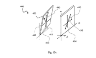
図13aを参照すると、本発明の一実施形態によるリターダ補償器の概略図が示される。リターダ補償器は、垂直入射でパネル404のFAを含む視野面に沿って、TN xLCDパネル404と縦列で示される補償プレート403である(例えば、パネルのFAは、図面の平面内である)。補償プレート403は、2つの負のCプレート・リターダ407a、407b間に配置されるOプレート・リターダ406を含む。組み合わせられたリターダ要素403は、傾斜されたプレート・リターダ(TPR)と呼ばれるものを形成するために、TN xLCDパネル404の面に対して角度θpt410で傾斜される。
Referring to FIG. 13a, a schematic diagram of a retarder compensator according to one embodiment of the present invention is shown. The retarder compensator is a
Oプレート・リターダ406は、プレート/層の面に対して斜めの角度で方向付けられたその光学軸(すなわち、C軸)を有する複屈折要素である。Oプレート・リターダ406の光学軸は、リターダ・プレート垂線に対して極角θc420で傾斜される(例えば、屈折率異方性を示すために使用される屈折率楕円体によって示されるように)。ここで使用される用語の光学軸は、均一に傾斜された複屈折層のC軸、または連続して広げられる複屈折層の平均C軸に関連する。屈折率楕円体の対応する面外傾斜は、θt421によって与えられ、ここで、θt+θc=90°である。Oプレート・リターダ要素406が、正の一軸性要素として構成されるとき、光学軸は、また遅軸である。Oプレート・リターダ406の遅軸方位角は、傾斜面(例えば、この面は、また図13aで描かれた面に対応する傾斜角度θpt全体を含む)に沿って配向される。Oプレート・リターダ406を製造するために適した材料のいくつかの実施例は、液晶ポリマー(LCP)材料、および単結晶水晶などの正の一軸性複屈折結晶材料を含む。任意に、Oプレート・リターダは、支持基板を含む。
O-
各−Cプレート・リターダ407a、407bは、プレート/層の面に対して垂直に方向付けられたその光学軸を有する複屈折要素である。−Cプレートは、垂直入射光線に関する任意の正味のリタデーションを一般に提供しないが(すなわち、垂直入射光は、複屈折性によって影響を受けない)、オフ軸(すなわち、光軸に対するある角度)の入射光線は、入射角度による正味のリタデーションを受ける。特に、正味のリターダンスは、入射角度とともに低減する(例えば、正味のリターダンスが、入射角度とともに増大する+Cプレートとは対照的に)。−Cプレート要素の407a、407bは、それらの光軸が、Oプレート複屈折要素の面に対して垂直に方向付けられるように、Oプレート406に結合される。−Cプレート407a、407bを製造するのに適した材料のいくつかの実施例は、ディスコティック液晶、およびディスコティック複屈折ポリマー化合物を含む。−Cプレート407a、407bを製造する1つの特に魅力的な方法は、Oプレート406の両側を構造性複屈折(form−birefringent)反射防止(FBAR)被覆で被覆することである。FBAR被覆において、複屈折性は、交互の屈折率を有する材料から形成された複数の薄膜層によって提供され、各薄膜層の厚みは、動作波長の分数である。面外の負の複屈折性の強度は、被覆の厚み、交互層間の屈折率の差異、および/または交互層の厚みにおける差異によって決定される。複数の薄膜層は、典型的に良く知られている様々な堆積技術の1つ(例えば、スパッタリングまたは他の真空堆積)を使用して、誘電体材料から形成されるので、−Cプレートは、プロジェクション・システムで見出される高い光束および/または高温環境での使用に良く適している。FBAR被覆は、例えば、米国特許第7170574号でさらに詳細に議論されている。
Each -
透過側からのサブ・システム400の図を示す概略図である図13bを同様に参照すると、リターダ補償器403は、回転軸440の周りを角度θptで傾斜される。回転軸440は、x軸に対して(例えば、パネルの長手側に対して)角度445(例えば、ほぼ75°)で示される。この傾斜された幾何形状は、表記(φ、θpt)を使用して記載されることができ、ここで、第1の値φは、プレート傾斜方位角(0°から360°の範囲)を記載し、第2の値θは、プレート傾斜極角(>0°)を記載する。例えば、プレート傾斜角度θptが10°に等しく、かつプレート傾斜方位角が−15°であるなら、この傾斜された幾何形状は、(−15°、10°)として定義される。代わりに、この傾斜された幾何形状は、リターダ補償器403が、−15°のプレート傾斜方位面に沿って10度の傾斜角度で搭載されることを述べることによって定義される。CCWプレートの回転が、その周りで行われる回転軸は、90°を加えたプレート傾斜方位角として定義されるので、−15°のプレート傾斜方位角は、75°の回転軸に対応する。一般に、回転軸440は、TNパネルが、垂直入射点(すなわち、大きな線形リターダンスの非対称性を有する)を通るリターダンス傾斜の最大量を示す視野方位角平面に隣接する象限にある。図8に示される実験によるTNリターダンスの結果において、この非対称面は、−45度の方位角に対応する。したがって、回転の公称軸は、リターダが傾斜されたとき、TPRから得られたリターダンスが、−45度方位角に沿ったパネルのリターダンスに対して応分の非対称性も示すような態様で、+45度で配向される。TPRの遅軸は、TNパネルの場合のように速軸の代わりに、この非対称面に沿って配向される。
Referring also to FIG. 13b, which is a schematic diagram illustrating a diagram of the
上記で議論されたように、TPR403の面内遅軸450の方向付けは、TPRおよびTN90 xLCDパネルの両方が、ほぼ同じリターダンス強度を有するとき、TN90 xLCDパネル404の面内遅軸430にほぼ垂直に(例えば、方位角方向に)配向される。より一般的な場合、TPR要素の正味のリターダンスは、パネル・リターダンス公差を考慮してより大きく作られ、時計回転は、コントラスト性能を最適化するために用いられる(すなわち、時計回転軸は、傾斜された面に対して垂直である)。この場合、回転軸、および/またはデカルト・リターダ要素の遅軸は、それぞれプレート傾斜方位面に垂直であるかつ平行であることから逸脱することがある。例えば、図13bに示されるように、回転軸440は、X軸から75度のCCWでほぼ配向され、一方、デカルト・リターダは、X軸から110度のCCWでほぼ配向された遅軸450を有する。Oプレート・デカルト・リターダ要素に関して、遅軸は、+Z軸に対して光学軸の鋭い極角を有する方位角平面に言及する。回転軸およびデカルト・リターダ遅軸の全体的な配向の3D斜視図が、図13cに示される。プレート傾斜の後、回転軸が、パネルxy平面に平行なままであることに留意されたい。デカルト・リターダは、システムX軸に対して極角傾斜411で、かつシステムY軸に対して極角傾斜412で配向される。
As discussed above, the orientation of the in-plane
再び図13aを参照すると、TPR403のSAは、傾斜されたOプレート・リターダ406のSA450および傾斜された−Cプレート・リターダ407a、407bのSAによって決定される。補償器プレートが傾斜されるとき、−Cプレート構成要素の遅軸の方向付けは、回転軸(例えば、角度445を有する)と平行に配向されることに留意されたい。したがって、Oプレート要素の両側に2つの−Cプレート要素を有するTPRに関して、コーン中心での光線は、440の向きに配向された第1の遅軸と、450の向きに配向された第2の遅軸と、440の向きに配向された第3の遅軸とを有する結果として生じた効果を受ける。一般に、Oプレート・リターダ406は、同じプレート傾斜角度での−Cプレート・リターダ407a、407bの負のリタデーション効果より小さなプレート傾斜角度で、より大きな正のリタデーション効果を生じる。したがって、OプレートのSA方向付けが、プレート傾斜方位面にほぼ沿って方向付けられ、かつOプレートの相対リタデーション強度が、−Cプレート・リターダの相対リターダンス強度より大きいとき、コーン中心光線は、負のCプレート・リターダが、Oプレートのリタデーション効果を低減しても、プレート傾斜方位に沿ってほぼ方向付けられたTPRの有効SAをみる。
Referring again to FIG. 13a, the
動作において、TN xLCDパネル404は、極値470および471を有し、かつハーフ・コーン角度θh475の境界を示す光の入射コーンの中心光線461が、垂直入射であるように配置される。傾斜されたプレート・リターダ(TPR)403は、コーン照明の中心光線461が、プレート傾斜角度θpt410によって決定される入射角度(AOI)θi460で−Cプレート407aに当たるように配置される。わずかな側方並進の後、コーンの中心光線461は、光線462としてTPR403およびTN xLCDパネル404の両方を出て行く。
In operation, the
コーンの上半分(例えば、470)における収束光線は、垂直入射光線より大きい(例えば、Oプレートからの正味のリターダンスより大きい)補償器リタデーションをみる。さらに、コーンの上半分(例えば、470)における収束光線は、垂直入射光線(例えば、パネルの面内および面外リターダンスから生じる)より大きなパネルの正味のリタデーション(リタデーション符号を含む)もみる。実際、1Dコーン照明内の全ての光線は、良好に補償されることを示すために、リターダ補償器403は、補償効率を計算するために単一層の一軸性Oプレート・リターダおよび単一層の一軸性−Cプレート・リターダ(例えば、2つの−Cプレート・リターダの407a、407bによって示される同じ−Cプレート・リターダンス)で近似された。
The convergent ray in the upper half of the cone (eg, 470) sees a compensator retardation that is greater than the normal incident ray (eg, greater than the net retardance from the O-plate). In addition, the convergent rays in the upper half of the cone (eg, 470) also see the panel's net retardation (including the retardation code) greater than the normal incident rays (eg, resulting from in-plane and out-of-plane retardance of the panel). In fact, to show that all rays in the 1D cone illumination are well compensated, the
表1は、TN xLCDパネルのFA面リターダンス特性と一致するために、傾斜されかつSA面リターダンス特性で構成される−Cプレート・リターダと結合された単一層の一軸性Oプレート・リターダを有するリターダ補償器に関して計算された面内リターダンスおよびCプレート・リターダンスを示す。シミュレーションの波長は520nmである。λ=520nmでのOプレートに関する屈折率{no、ne}は、{1.502、1.655}であり、一方、λ=520nmでの−Cプレートに関する屈折率{no、ne}は、{1.655、1.502}である。 Table 1 shows a single layer uniaxial O-plate retarder combined with a C-plate retarder that is tilted and configured with SA-plane retardance characteristics to match the FA plane retardance characteristics of the TN xLCD panel. Figure 5 shows in-plane retardance and C-plate retardance calculated for a retarder compensator with. The simulation wavelength is 520 nm. lambda = the refractive index on O plate at 520 nm {n o, n e} is {1.502,1.655}, whereas, lambda = -C plate relates to the refractive index at 520 nm {n o, n e } Is {1.655, 1.502}.
表1によれば、必要なプレート傾斜角度θptおよび必要なCプレート・リターダンスの両方は、Oプレート屈折率楕円体の面外傾斜角度θtに応じて変化する。これらのパラメータの表示図が図14に示される。Cプレート・リターダンス要件は、75°より大きいOプレート屈折率楕円体の傾斜角度θtで近似的に大きくなることは明らかである。70°より小さいOプレート屈折率楕円体の傾斜角度θtで、Cプレート・リターダンスは、大きく変化しないが、必要なプレート傾斜角度θptは、Oプレート屈折率楕円体の傾斜角度θtが低減すると、連続して増大する。したがって、プレート傾斜角度θptとCプレート・リターダンスとの間のトレードオフを調整するために、かつTN xLCDパネルのFA面線形リターダンス特性に一致された遅軸の面線形特性を生じるために、Oプレート屈折率楕円体の傾斜角度θtは、典型的には30°と75°との間であり、より可能性があるのは50°と70°との間である。 According to Table 1, both the required plate tilt angle θ pt and the required C plate retardance vary with the out-of-plane tilt angle θ t of the O-plate refractive index ellipsoid. A display diagram of these parameters is shown in FIG. C-plate retardance requirement is obviously approximately larger that at the inclination angle theta t of 75 ° greater than O plate refractive index ellipsoid. Although the C-plate retardance does not change greatly at an inclination angle θ t of the O-plate refractive index ellipsoid smaller than 70 °, the required plate inclination angle θ pt is equal to the inclination angle θ t of the O-plate refractive index ellipsoid. As it decreases, it increases continuously. Therefore, to adjust the trade-off between plate tilt angle θ pt and C-plate retardance and to produce a slow-axis planar linear characteristic that is consistent with the FA planar linear retardance characteristic of the TN xLCD panel The tilt angle θ t of the O-plate refractive index ellipsoid is typically between 30 ° and 75 °, more likely between 50 ° and 70 °.

コントラスト効率の例示的な計算として、−Cプレート・リターダに結合された単一層の一軸性のOプレート・リターダを有し、かつ−45°方位角平面に沿ったほぼ10.3°に傾斜された(または+45°方位角で回転軸の周りのCCW回転)リターダ補償器がモデル化された。この傾斜されたプレート幾何形状は、(−45°、10.3°)と呼ばれ、ここで、第1の値は、プレート傾斜方位角(0°から360°の範囲)を記載し、第2の値は、プレート傾斜極角(>0°)を記載する。−45°でのプレート傾斜方位角(PTA)は、TN xLCDパネルのSA面(例えば、+40.1°)にほぼ直交する。単一層のOプレートは、50°の面外傾斜でその屈折率楕円体配向を有し、12.6nmの面内リターダンスを生じる。−Cプレートは、λ=520nmで−525nmのリターダンスを有する。12.6nmの面内リターダンスおよび10.3°のプレート傾斜は、50°の面外傾斜に関して表1で計算された対応する値とは異なることに留意されたい。なぜなら、このモデルは、{1.598、1.670}の屈折率{no、ne}(例えば、専売の液晶ポリマー(LCP)に対応する)を有するOプレートを使用するからである。一実施形態において、1つ以上の誘電体の構造性複屈折ARスタックから形成される負のCプレートは、{1.655、1.502}の屈折率を有する等しいCプレート・リターダで近似される。
An exemplary calculation of contrast efficiency has a single layer uniaxial O-plate retarder coupled to a -C plate retarder and is tilted to approximately 10.3 ° along a -45 ° azimuthal plane. A retarder compensator was modeled (or CCW rotation around the rotation axis at + 45 ° azimuth). This tilted plate geometry is called (−45 °, 10.3 °), where the first value describes the plate tilt azimuth (
−Cプレート・リターダに結合された単一層の一軸性のOプレート・リターダのコノスコープ・リターダンス構成要素は、λ=520nmでほぼf/2.4のコーン照明に関して図15に示される。左の表示図は、線形リターダンス・コノスコープ特性を示し、それは、コーン中心光線によって見られる遅軸が、パネル遅軸にほぼ直交する(例えば、TN90 xLCDパネルに関する+40.1°に対するTPRに関する−45°)ことを除いて、それは、実験によるTN xLCDパネルに類似する線形リターダンス分布を有する(例えば、図8を参照)。傾斜された面は、TPRおよび実験TN xLCDパネルの一致したリターダンス強度によって必要とされるように(例えば、コーン中心光線に関して両方とも〜2.2nmリターダンス)、パネルの遅軸に対してほぼ交差された軸構成を課すために、この計算実施例において−45°であるように選択されたことに留意されたい。図15における中心表示図は、TPRの遅軸分布を示す。それは、図8に示される実験によるTN xLCDの遅軸分布に対してほぼ90°のオフセットを有する(例えば、40.1°の平均に対する−45°の平均)。単一層のOプレート複屈折構造から予測されるように、単一パス透過に関する無視できる円リターダンス構成要素がある。これは、図15の右側の表示図で示される。 The conoscopic retardance component of a single layer uniaxial O-plate retarder coupled to a C-plate retarder is shown in FIG. 15 for a cone illumination of λ = 520 nm and approximately f / 2.4. The display on the left shows the linear retardance conoscopic characteristic, which is that the slow axis seen by the cone center ray is approximately orthogonal to the panel slow axis (eg, for TPR for + 40.1 ° for a TN90 xLCD panel- 45 °), it has a linear retardance distribution similar to the experimental TN xLCD panel (see, eg, FIG. 8). The tilted surface is approximately relative to the slow axis of the panel, as required by the matched retardance intensity of the TPR and experimental TN xLCD panels (eg, both ~ 2.2 nm retardance with respect to the cone center ray). Note that in this calculation example, it was chosen to be −45 ° to impose a crossed axis configuration. The center display diagram in FIG. 15 shows the TPR slow axis distribution. It has an approximately 90 ° offset to the slow axis distribution of the TN xLCD according to the experiment shown in FIG. 8 (eg, an average of −45 ° relative to an average of 40.1 °). There are negligible circular retardance components for single-pass transmission, as expected from a single layer O-plate birefringent structure. This is shown in the display on the right side of FIG.
TPRおよび実験TN xLCDパネル・データを含む2ステージ・システム計算は、図16に示される正味のコノスコープ・リターダンス構成要素を生じる。この図面の左、中央、および右表示図は、f/2.4収束コーンに対する線形リターダンス、遅軸、および円リターダンス分布を表す。全ての3つの表示図上の陰を付けたグレー・スケールは、実験TN xLCDパネル・データ(例えば、図8)およびTPRデータ(例えば、図15)で使用された対応するスケールに類似する。線形リターダンス表示図(左)にしたがって、実験TN xLCDパネルの残留線形リターダンスは、TPRの線形リターダンスによって良好に補償される。実際、2ステージ・システムは、180°コーン方位角周りの領域を除いて、全てのコーン照明角度で〜0nmの正味のリターダンスを示す。2ステージ・システムの遅軸分布は、正味の線形リターダンスが0nmに近いので重要ではない。2ステージ・システムの正味の円リターダンスは、TPRが円リターダンスを生じないので、実験TN xLCDパネルとほぼ同じ特性を有する。TN xLCDパネルにおける円リターダンスは、コントラスト補償器としてモデル化されたTPRを使用して最大に達成可能なコントラストを最終的に制限する。このコントラスト計算の実施例において、実験TN xLCDパネルは、λ=520nmで300:1のコントラストを有するようにモデル化され、一方、TPRで補償された同じパネルは、4100:1のコントラストを生じる。この補償されたコントラストは、光学システム・ベースライン・コントラスト(例えば、交差偏光子漏洩などに起因する)によって低く重み付けられることがわかる。予測されるシステム・コントラスト比は、6000:1の実際のシステム・ベースライン・コントラストで2400:1である。交差偏光子漏洩のコノスコープ特性は、図17に示される。左手表示図は、右手表示図におけるパネルだけの漏洩強度の陰が付けられたグレー・スケールの1/10を有する、補償されたパネル漏洩の強度結果を示す。補償されたパネル漏洩表示図において、第4象限の周りのコーン縁部の視野角は、パネルにおける残る補償されていない円リターダンスの明示である最も厳しい漏洩を有する。同様に、パネルだけの漏洩特性は、また、残留線形および円リターダンスの組み合わせられた効果に起因して、第4象限におけるコーン縁部周りで最も厳しい漏洩を有する。 A two stage system calculation including TPR and experimental TN xLCD panel data results in the net conoscopic retardance component shown in FIG. The left, center, and right views of this figure represent the linear retardance, slow axis, and circular retardance distributions for the f / 2.4 convergence cone. The shaded gray scale on all three display diagrams is similar to the corresponding scale used in the experimental TN xLCD panel data (eg, FIG. 8) and TPR data (eg, FIG. 15). According to the linear retardance display diagram (left), the residual linear retardance of the experimental TN xLCD panel is well compensated by the linear retardance of the TPR. In fact, the two-stage system exhibits a net retardance of ˜0 nm at all cone illumination angles except for the region around the 180 ° cone azimuth. The slow axis distribution of the two stage system is not important as the net linear retardance is close to 0 nm. The net circular retardance of the two stage system has almost the same characteristics as the experimental TN xLCD panel because the TPR does not produce a circular retardance. Circular retardance in TN xLCD panels ultimately limits the maximum achievable contrast using TPR modeled as a contrast compensator. In this contrast calculation example, the experimental TN xLCD panel is modeled to have a 300: 1 contrast at λ = 520 nm, while the same panel compensated with TPR yields a 4100: 1 contrast. It can be seen that this compensated contrast is weighted lower by the optical system baseline contrast (eg, due to crossed polarizer leakage, etc.). The expected system contrast ratio is 2400: 1 with an actual system baseline contrast of 6000: 1. The conoscopic characteristics of crossed polarizer leakage are shown in FIG. The left hand view shows a compensated panel leak strength result having 1/10 of the gray scale shaded of the panel only leak strength in the right hand view. In the compensated panel leak display, the viewing angle of the cone edge around the fourth quadrant has the most severe leak, which is manifestation of the remaining uncompensated circular retardance in the panel. Similarly, the panel-only leakage characteristics also have the most severe leakage around the cone edge in the fourth quadrant due to the combined effects of residual linearity and circular retardance.
上記のコントラスト計算実施例を用いて、実験TN xLCDパネルと対にされるTPRのコントラスト補償効果が示された。市販の光エンジン応用において、TN xLCDおよびTPRの両方のパラメータは、均一な分布を有する。特に、パネル・オフ状態リターダンスおよび軸方向付けは、パネル毎に変化し、また温度ドリフト、機械的搭載応力などとともに変化する。TPRは、Oプレート傾斜角度、面内リターダンス、およびCプレート・リターダンス強度の分布を有する。能動的に切り替えられるTN xLCDは、受動Oプレート・リターダ(例えば、最大±5%のリターダンス分散)より大きなリターダンス分散(例えば、±30%と同じ大きさ)を有することが予測される。パネルおよびTPRの両方の全体の製造分散を包含することを目的とする実際のTPR設計は、Oプレートの面内リターダンスを増加しかつ1つまたは組み合わせのTPRの極角傾斜の調整を使用することと、光学系Z軸の周りでTPRを回転することと、傾斜面に沿ってそのデバイス垂線の周りでTPRを回転することと(例えば、時計回転することと)、かつ暗ステージ・パネル・リターダンスおよび/または遅軸/速軸が、所定のTPRの要件に一致することができるようにTN xLCDの電圧/温度制御の非機械的手段とを含む。 Using the contrast calculation example above, the contrast compensation effect of the TPR paired with the experimental TN xLCD panel was shown. In commercial light engine applications, both TN xLCD and TPR parameters have a uniform distribution. In particular, panel off-state retardance and axial orientation vary from panel to panel and vary with temperature drift, mechanical mounting stress, and the like. The TPR has a distribution of O-plate tilt angle, in-plane retardance, and C-plate retardance intensity. An actively switched TN xLCD is expected to have a retardance variance (eg, as large as ± 30%) that is greater than a passive O-plate retarder (eg, a maximum ± 5% retardance variance). An actual TPR design intended to encompass the entire manufacturing variance of both the panel and TPR increases the in-plane retardance of the O-plate and uses one or a combination of TPR polar angle adjustments. Rotating the TPR about the optical system Z-axis, rotating the TPR about the device normal along the inclined surface (eg, rotating clockwise), and the dark stage panel Non-mechanical means of voltage / temperature control of the TN xLCD so that the retardance and / or slow / fast axis can be matched to the requirements of a given TPR.
製造可能なTPR設計の例示として、50°の屈折率楕円体傾斜および32.0nmの面内リターダンスを有するOプレート・リターダは、−525nmの負のCプレート・リターダに結合される(両方ともλ=520nmに対して言及されるリターダンス)。組み合わせられたリターダは、−15°のプレート傾斜方位角に沿った9°極角で傾斜される。この場合において、生の補償されたコントラストは、図18に示されるように16000:1であり、これは、図17で示されるほぼ交差された軸の補償解決方法のコントラストの4倍に近い。図18において左および右手表示図で示される陰が付けられたグレー・スケールは、図17におけるグレー・スケールと同一である。−15°の方位角平面に沿った9°で傾斜された、32nmのTPRのコノスコープ・リターダンス構成要素は、f/2.4コーンの座標に対して図19に示される。Oプレート・リターダの遅軸は、−64.0°によって「時計回転」される(面外傾斜後、およびプレート傾斜方位に含まれることから離れた後、プレート垂線の周りのCW回転)。コノスコープTPR線形リターダンスは、TN xLCD線形リターダンス特性とは似ていないが、リターダンス特性ならびにその遅軸分布(中心表示図に示されるようにほぼ±90°に近い)は、過剰時計回転の要件を満たす。TPRリターダンス特性と実験TN xLCDリターダンスとの組み合わせは、図20に示される2ステージ・リターダンス特性を生じる。対にされたデバイスの正味の線形リターダンスは、0nmに近づかないが、それらの組み合わされた線形リターダンス効果は、全てのコーン角度に関する交差偏光子にほぼ平行/直交して配向された複屈折軸を結果として生じることが見られる。TN xLCDパネルにおける線形リターダンスの補償に加えて、このTPRは、パネルの円リターダンスも低減する。これは、実験TN xLCDの円リターダンスに対する右表示図における低減された円リターダンスによって示される(例えば、パネルにおける0.5nmに対するオン軸0.1nm、およびパネルにおける−11.5〜5.1nmに対する−5.8〜2.3nmの円リターダンス範囲)。 As an example of a manufacturable TPR design, an O-plate retarder with a 50 ° index ellipsoid tilt and 32.0 nm in-plane retardance is coupled to a -525 nm negative C-plate retarder (both Retardance mentioned for λ = 520 nm). The combined retarder is tilted at a 9 ° polar angle along the −15 ° plate tilt azimuth. In this case, the raw compensated contrast is 16000: 1 as shown in FIG. 18, which is close to four times the contrast of the nearly crossed axis compensation solution shown in FIG. The shaded gray scale shown in the left and right hand views in FIG. 18 is the same as the gray scale in FIG. A 32 nm TPR conoscopic retardance component, tilted at 9 ° along the -15 ° azimuthal plane, is shown in FIG. 19 for f / 2.4 cone coordinates. The slow axis of the O-plate retarder is “clockwise” by −64.0 ° (CW rotation around the plate normal after out-of-plane tilt and after leaving the plate tilt orientation). The conoscopic TPR linear retardance is not similar to the TN xLCD linear retardance characteristic, but the retardance characteristic and its slow axis distribution (nearly ± 90 ° as shown in the center view) are overclockwise. Meet the requirements. The combination of the TPR retardance characteristic and the experimental TN xLCD retardance produces the two stage retardance characteristic shown in FIG. The net linear retardance of the paired devices does not approach 0 nm, but their combined linear retardance effect is birefringence oriented approximately parallel / orthogonal to the crossed polarizers for all cone angles It can be seen that the resulting axis. In addition to compensating for linear retardance in TN xLCD panels, this TPR also reduces the circular retardance of the panel. This is shown by the reduced circular retardance in the right display for the experimental TN xLCD circular retardance (eg, on-axis 0.1 nm vs 0.5 nm in the panel, and −11.5-5.1 nm in the panel). -5.8 to 2.3 nm circular retardance range).
傾斜されたプレート・リターダの構造は、Oプレート厚みを横切る均一な遅軸方位角に起因する任意の円リターダンスを生じない。しかしながら、TPRが、TN xLCDパネル・リターダンスを補償するために使用されるとき、パネル・リターダンスと組み合わせてコーン光線によって見られるTPRリターダンスは、不均一なリターダ縦列を形成する。パネルの垂直入射は、ほぼ+0.5nmの円リターダンスを生じる。TPRとパネル線形リターダンスとの組み合わせは、また、+0.5nmの残留パネル円リターダンスを低減するために、負の円リターダンスを生じなければならない。負の円リターダンスを得るために、2つ以上のリターダ要素の縦列は、入力から出力方向への時計方向を通してツイストする遅軸方向付けを有するべきである(左側は、光伝播の方向で親指ポインティング、および遅軸回転の意味の指ポインティングでツイストする)。この実施例において、TPRは、ほぼ−88.2°(また91.8°)で配向されたその遅軸を有し、一方、パネルは、ほぼ+40.1°で配向されたその遅軸を有する。もたらされた円リターダンスは、符号が負であり、2ステージ・システムの垂直入射の円リターダンスは、低減される。同様に、全ての他のコーン光線は、不均一なリターダ縦列の形成に適切な手を有し、f/2.4コーン内の最も大きな正および最も大きな負のパネル円リターダンスの両方は、部分的に補償される。したがって、それ自体が円リターダンスを含まない傾斜されたプレート・リターダの応用は、上記補償要件(d)によるパネル円リターダンスを低減する手段を提供する。 The tilted plate retarder structure does not produce any circular retardance due to the uniform slow axis azimuth across the O-plate thickness. However, when TPR is used to compensate for TN xLCD panel retardance, TPR retardance seen by cone rays in combination with panel retardance forms a non-uniform retarder column. Normal incidence of the panel produces a circular retardance of approximately +0.5 nm. The combination of TPR and panel linear retardance must also produce a negative circular retardance to reduce the residual panel circular retardance of +0.5 nm. To obtain negative circular retardance, the column of two or more retarder elements should have a slow axis orientation that twists through the clockwise direction from the input to the output direction (the left side is the thumb in the direction of light propagation) Twist with pointing and finger pointing meaning slow axis rotation). In this example, the TPR has its slow axis oriented at approximately -88.2 ° (also 91.8 °), while the panel has its slow axis oriented at approximately + 40.1 °. Have. The resulting circular retardance is negative in sign and the normal incidence circular retardance of the two stage system is reduced. Similarly, all other cone rays have the right hand to form a non-uniform retarder column, and both the largest positive and largest negative panel circle retardances within the f / 2.4 cone are Partially compensated. Therefore, the application of a tilted plate retarder that itself does not include a circular retardance provides a means to reduce the panel circular retardance according to the compensation requirement (d) above.
いくつかのリターダ補償器が製造された。リターダ組立品は、LCPデカルトOプレート・リターダおよびFBAR−Cプレート要素のモノリシック集積を使用する。リターダは、所定の回転軸に周りで所定の傾斜角度で配向された。コントラスト最適化は、そのプレート垂直軸の周りでリターダ組立品を時計回転して(すなわち、回転して)達成された。パネル・オンおよびオフ状態の輝度値は、スペクトル分解検出器システムを用いて収集され、光応答機能によって重み付けられた。コントラスト結果は、図21に示される。緑チャネルにおいて、TPRは、ほぼ230:1からほぼ1050:1へパネル・コントラストを改善した。利得係数は4倍より大きい。明らかに、本発明の一実施形態により設計され、かつTNパネルを組み込むプロジェクタ・システムに応用されるリターダ補償器は、著しいコントラスト増強を提供する。 Several retarder compensators were manufactured. The retarder assembly uses a monolithic integration of LCP Cartesian O-plate retarder and FBAR-C plate elements. The retarder was oriented at a predetermined tilt angle around a predetermined axis of rotation. Contrast optimization was achieved by clockwise (ie, rotating) the retarder assembly about its plate vertical axis. Panel on and off state luminance values were collected using a spectrally resolved detector system and weighted by the light response function. The contrast result is shown in FIG. In the green channel, TPR improved panel contrast from approximately 230: 1 to approximately 1050: 1. The gain factor is greater than 4 times. Clearly, a retarder compensator designed according to one embodiment of the present invention and applied to a projector system incorporating a TN panel provides significant contrast enhancement.
TPRを使用するときに考慮する1つのことは、負のCプレート・リターダの波長分散である。Oプレート・リターダは、TN xLCDパネルで見出されるLCに類似する材料屈折率分散を有する複屈折材料(例えば、LCP)を使用してしばしば構成されるが、−Cプレート・リターダは、1つ以上のFBAR被覆からしばしば形成される。上述のように、FBAR被覆は、典型的に、複数の交互の低および高屈折率の誘電体薄層から製造される。大きな有効な構造性複屈折を提供するために、屈折率コントラスト(低屈折率に対する高屈折率の比)は、一般的に非常に高い。例えば、FBAR被覆は、しばしば交互のタンタラおよびシリカ層から形成される。タンタラなどの高屈折率材料は、LCDパネルにおけるLC材料より分散的である。したがって、TPRで使用されるFBAR被覆は、任意にCプレート・リターダンス分散を低減するように設計される。 One thing to consider when using TPR is the chromatic dispersion of the negative C-plate retarder. O-plate retarders are often constructed using birefringent materials (e.g., LCP) that have a refractive index dispersion similar to LC found in TN xLCD panels, but more than one -C plate retarder Often formed from a FBAR coating. As noted above, FBAR coatings are typically fabricated from a plurality of alternating low and high index dielectric thin layers. In order to provide a large effective structural birefringence, the refractive index contrast (ratio of high refractive index to low refractive index) is generally very high. For example, FBAR coatings are often formed from alternating tantala and silica layers. High refractive index materials such as tantala are more dispersive than LC materials in LCD panels. Thus, the FBAR coating used in TPR is optionally designed to reduce C-plate retardance dispersion.
計算実施例として、4つの異なるFBARスタック設計がモデル化された。第1のFBAR設計は、30nmH/45nmLの繰り返しセグメントを含み、第2のFBAR設計は、20nmH/30nmLの繰り返しセグメントを含み、第3のFBAR設計は、15nmH/23nmLの繰り返しセグメントを含み、かつ第4のFBAR設計は、10nmH/15nmLの繰り返しセグメントを含んだ。各場合において、「H」は、タンタラの高屈折率層に言及し、「L」は、シリカの低屈折率層に言及する。各4つのスタックは、λ=520nmで−340nmのCプレート・リターダンス、および460〜580nm内の0.1%未満の反射率を目標とした。各場合において、H/L層厚みの比は、ほぼ同じであり、一方、交互のH/L層の組み合わされた厚みは変更された。 As a computational example, four different FBAR stack designs were modeled. The first FBAR design includes 30 nmH / 45 nmL repeating segments, the second FBAR design includes 20 nmH / 30 nmL repeating segments, the third FBAR design includes 15 nmH / 23 nmL repeating segments, and the first Four FBAR designs included 10 nmH / 15 nmL repeat segments. In each case, “H” refers to the tantala high index layer and “L” refers to the silica low index layer. Each of the four stacks targeted a C-plate retardance of λ = 520 nm and −340 nm, and a reflectivity of less than 0.1% within 460-580 nm. In each case, the ratio of H / L layer thickness was approximately the same, while the combined thickness of alternating H / L layers was changed.
7°のプレート傾斜角度(またコーン中心光線の入射角度)で計算されたリターダンス・スペクトルが図22に示される。4つのFBARスタックの最良の分散性能は、最も薄い繰り返し層(例えば、第4のFBAR設計)から生じる。構造性複屈折の理論は、「H」および「L」の両方の層厚みが0nmに近づく準静的状況に基づく。したがって、かなりの「H」および「L」層で形成された繰り返しセグメントは、構造性複屈折の理論の示唆より大きな分散である。所定の実施例において、最も大きな分散性の「厚い」繰り返し対は、λ=520nmで公称リターダンスに対する短いおよび長い波長縁部で+19.5/−11.3%のリターダンスの分散を生じる。他方、最も小さな分散性の「薄い」繰り返し対は、対応する波長点で+8.9%/−6.0%のリターダンスの分散を生じる。実際に、所定の真空堆積プロセスで製造可能なものと、必要な波長帯域にわたる最良のコントラスト補償との間のトレードオフがある。 The retardance spectrum calculated at a plate tilt angle of 7 ° (and the incident angle of the cone center ray) is shown in FIG. The best dispersion performance of the four FBAR stacks results from the thinnest repeating layer (eg, the fourth FBAR design). The theory of structural birefringence is based on a quasi-static situation where both “H” and “L” layer thicknesses approach 0 nm. Thus, repetitive segments formed with significant “H” and “L” layers are more dispersive than suggested by structural birefringence theory. In a given embodiment, the largest dispersive “thick” repeat pair produces a retardance dispersion of + 19.5 / −11.3% at the short and long wavelength edges relative to the nominal retardance at λ = 520 nm. On the other hand, the smallest dispersive “thin” repeat pair produces a retardance dispersion of +8.9% / − 6.0% at the corresponding wavelength point. In fact, there is a trade-off between what can be produced with a given vacuum deposition process and the best contrast compensation over the required wavelength band.
交互のH/L層の適切な組み合わされた厚みを選択することに加えて、「L」層厚みに対する「H」層厚みの比は、Cプレート・リターダンス分散にも影響する。例えば、50nmの対の厚みが、良好な製造公差に関して最も薄い組み合わせられた層厚みであるなら、リターダンス分散を最小化することができるまだいくつかの設計の変形が存在する。 In addition to choosing an appropriate combined thickness of alternating H / L layers, the ratio of “H” layer thickness to “L” layer thickness also affects C-plate retardance dispersion. For example, if a 50 nm pair thickness is the thinnest combined layer thickness for good manufacturing tolerances, there are still some design variations that can minimize retardance dispersion.
計算実施例として、さらに5つの異なるFBARスタック設計がモデル化された。第5のFBAR設計は、10nmH/40nmLの繰り返しセグメントを含み、第6のFBAR設計は、20nmH/30nmLの繰り返しセグメントを含み、第7のFBAR設計は、25nmH/25nmLの繰り返しセグメントを含み、第8のFBAR設計は、30nmH/20nmLの繰り返しセグメントを含み、かつ第9のFBAR設計は、40nmH/10nmLの繰り返しセグメントを含んだ。各場合において、「H」は、タンタラの高屈折率層に言及し、「L」は、シリカの低屈折率層に言及する。各これら5つのスタックは、λ=520nmで公称−340nmのCプレート・リターダンスを目標とした。 As a computational example, five more different FBAR stack designs were modeled. The fifth FBAR design includes 10 nmH / 40 nmL repeating segments, the sixth FBAR design includes 20 nmH / 30 nmL repeating segments, the seventh FBAR design includes 25 nmH / 25 nmL repeating segments, The FBAR design included 30 nmH / 20 nmL repeat segments and the ninth FBAR design included 40 nmH / 10 nmL repeat segments. In each case, “H” refers to the tantala high index layer and “L” refers to the silica low index layer. Each of these five stacks was targeted for a nominal -340 nm C-plate retardance at λ = 520 nm.
7AOIおよびλ=520nmでのリターダンスの分散スペクトルが図23に示される。繰り返しセグメント内の「H」部分がより高くなると、Cリターダンスの分散がより大きくなる(例えば、第9番目の設計)ことが見出された。したがって、10nmH/40nmL設計(例えば、第9番目の設計)が、最も好ましい設計である。しかしながら、50:50の比に近くない「H」および「L」の対にされた厚みを選択することは、有効な構造性複屈折を低減する。したがって、5つの実施例における最良および最悪の分散設計は、同じ量のCリターダンスを生じるために著しくより多い層を必要とする。本明細書で参照されるCリターダンス量は、λ=520nmで{1.655、1.502}の屈折率を有する単一層の一軸性の負のCプレート・リターダ(および提供された他の波長における全屈折率分散)の等価のオフ軸リタデーション効果に向けられたことに留意されたい。合計の異常および正常屈折率を参照するCリターダンス量が、本明細書に報告される結果とは極めて異なることがある。 The dispersion spectrum of the retardance at 7 AOI and λ = 520 nm is shown in FIG. It has been found that the higher the “H” portion in the repeat segment, the greater the variance of the C retardance (eg, the ninth design). Therefore, the 10 nm H / 40 nm L design (eg, the ninth design) is the most preferred design. However, choosing an “H” and “L” paired thickness that is not close to a 50:50 ratio reduces effective structural birefringence. Thus, the best and worst distributed designs in the five examples require significantly more layers to produce the same amount of C retardance. The amount of C retardance referred to herein is a single layer uniaxial negative C-plate retarder (and other provided ones) with a refractive index of {1.655, 1.502} at λ = 520 nm. Note that it was directed to an equivalent off-axis retardation effect of total refractive index dispersion at wavelength. The amount of C retardance referring to the total anomaly and normal refractive index can be very different from the results reported herein.
図24を参照すると、本発明の他の実施形態によるリターダ補償器の概略図が示される。リターダ補償器は、垂直入射でパネル504のFAを含む視野面に沿って、TN xLCDパネル504と縦列で示される補償プレート503である(例えば、パネルのFAは、図面の平面内である)。補償プレート503は、2つの負のCプレート・リターダ507a、507b間に配置されるAプレート・リターダ506を含む。組み合わせられたリターダ要素503は、傾斜されたプレート・リターダ(TPR)と呼ばれるものを形成するために、TN xLCDパネル504の面に対して角度θptで傾斜される。
Referring to FIG. 24, a schematic diagram of a retarder compensator according to another embodiment of the present invention is shown. The retarder compensator is a
Aプレート・リターダ506は、プレート/層の面に対して平行に方向付けられたその光学軸を有する複屈折要素である(例えば、異方性を示すために使用される屈折率楕円体によって示されるように)。Aプレート・リターダ要素506が、正の一軸性要素として構成されるとき、光学軸は、また遅軸である。Aプレート・リターダ506を製造するために適した材料のいくつかの実施例は、伸張されたホイル・リターダ、液晶ポリマー、および単結晶水晶を含む。任意に、Aプレート・リターダ506は、支持基板を含む。
The
各−Cプレート・リターダ507a、507bは、プレート/層の面に対して垂直に方向付けられたその光学軸を有する複屈折要素である。−Cプレートは、垂直入射光線に関する任意の正味のリタデーションを一般に提供しないが(すなわち、垂直入射光は、複屈折性によって影響を受けない)、オフ軸(すなわち、光軸に対するある角度)の入射光線は、入射角度に比例する正味のリタデーションを受ける。特に、正味のリターダンスは、入射角度とともに低減する(例えば、正味のリターダンスが、入射角度とともに増大する+Cプレートとは対照的に)。−Cプレート要素の507a、507bは、それらの光軸が、Aプレートの面に対して垂直に向けられるように、Aプレート506に結合される。−Cプレート507a、507bを製造するのに適した材料のいくつかの実施例は、ディスコティック液晶、およびディスコティック複屈折ポリマー化合物を含む。−Cプレート507a、507bを製造する1つの特に魅力的な方法は、Aプレート506の両側を構造性複屈折反射防止(FBAR)被覆で被覆することである。
Each -
上記で議論されたように、組み合わされたAプレート/−Cプレート・リターダ要素503は、TN xLCDパネル504の面に対して角度θptでサブ・システム500内で傾斜される。より詳細には、リターダ補償器503は、所定の回転軸(図示されないが、図面の面に垂直)の周りを角度θptで傾斜される。Aプレート屈折率楕円体の傾斜角度θtは、ほぼ0°であるので、Aプレートのプレート傾斜角度θptは、典型的に、Oプレート・リターダを利用するデカルト・リターダ要素の対応するプレート傾斜角度より大きい。
As discussed above, the combined A-plate / -C-
図13aおよび図24を参照して記載された各実施形態において、Aおよび/またはOプレートの傾斜は、傾斜されていない構成に対する、A/Oプレート・デカルト・リターダ要素の光学軸と透過軸(例えば、z軸)との間の角度が低減するように実施される。したがって、A/Oプレートの有効面内リターダンスは低減され、コーン軸の周りの大きな線形リターダンスの非対称性は、同じ方位角平面に沿ったTNパネルの線形リターダンス傾斜に一致するように誘導される。デカルト・リターダ要素(例えば、AプレートまたはOプレート)の正味のリターダンスと傾斜された−Cプレートとの間の相互作用は、有効リターダンス傾斜の整形を可能にする。1つの方位角方向に沿って、傾斜されたデカルト・リターダ要素の正味のリターダンスは、平坦なリターダンス特性を生成するように傾斜された−Cプレート・リターダの正味のリターダンスに対抗する。反対側の方位角方向(すなわち、180度オフセット)に沿って、光線は、傾斜されたデカルト・リターダ要素の光学軸近くを伝播し、鋭いリターダンス傾斜が、傾斜された−Cプレート要素から得られる。 In each embodiment described with reference to FIGS. 13a and 24, the tilt of the A and / or O plate is such that the optical and transmission axes of the A / O plate Cartesian retarder element for an untilted configuration ( For example, the angle with respect to the z-axis) is reduced. Thus, the effective in-plane retardance of the A / O plate is reduced and the large linear retardance asymmetry around the cone axis is induced to match the linear retardance slope of the TN panel along the same azimuthal plane. Is done. The interaction between the net retardance of the Cartesian retarder element (eg, A plate or O plate) and the tilted -C plate allows shaping of the effective retardance tilt. Along one azimuthal direction, the net retardance of the tilted Cartesian retarder element counters the net retardance of the tilted -C plate retarder to produce a flat retardance characteristic. Along the opposite azimuthal direction (ie, 180 degree offset), the rays propagate near the optical axis of the tilted Cartesian retarder element, and a sharp retardance tilt is obtained from the tilted -C plate element. It is done.
換言すれば、1つ以上の−Cプレート被覆で被覆されたA/Oプレートを傾斜することは、また、リターダ補償器の非対称の線形リターダンス特性が、オフ状態のTN xLCDパネルの非対称の線形リターダンス特性に一致し/補足するように、調整されることができる他の変数を提供する。さらに、1つ以上の−Cプレート被覆で被覆されたA/Oプレートを傾斜することは、傾斜されたプレート・リターダが、少なくとも部分的にパネル円リターダンスを相殺し、それによってTN xLCDパネルのコントラストを改善するように、傾斜されたプレート・リターダが、透過軸に対して平行ではない軸の周りでほぼ交差された軸構成から離れて時計回転されることを可能にする。したがって、傾斜されたプレート・リターダは、また、上述の第4番目の要件(d)を満足する。 In other words, tilting an A / O plate coated with one or more -C plate coatings also causes the asymmetric linear retardance characteristic of the retarder compensator to be asymmetric linear of the off-state TN xLCD panel. Provide other variables that can be adjusted to match / complement the retardance characteristics. In addition, tilting an A / O plate coated with one or more -C plate coatings causes the tilted plate retarder to at least partially offset the panel circular retardance, thereby reducing the TN xLCD panel's In order to improve contrast, the tilted plate retarder can be rotated clockwise away from a substantially crossed axis configuration about an axis that is not parallel to the transmission axis. Therefore, the tilted plate retarder also satisfies the fourth requirement (d) described above.
上述のように、補償プレートの傾斜は、パネルの線形リターダンスの非対称性に一致されることができる線形リターダンスにおける傾斜を導入する。特に、補償プレートは、液晶プレートのリターダンス非対称性に類似するリターダンス非対称性を提供するように選択された、回転軸の周りを傾斜される。有利には、傾斜されたプレート・リターダは、その遅軸が、AプレートまたはOプレートによって設定されるデカルト・リターダとして機能する。傾斜されたプレート・リターダが、交差軸構成から離れて時計回転されると、その線形リターダンスの非対称性は、同じ方位角平面に沿ったパネル線形リターダンスの非対称性で配向され、一方、傾斜されたAプレートまたはOプレート・リターダの面内構成要素は、必要な方向付けでリターダ補償器の遅軸を固定する。 As mentioned above, the slope of the compensation plate introduces a slope in linear retardance that can be matched to the asymmetry of the linear retardance of the panel. In particular, the compensation plate is tilted about an axis of rotation that is selected to provide a retardance asymmetry that is similar to the retardance asymmetry of the liquid crystal plate. Advantageously, the tilted plate retarder functions as a Cartesian retarder whose slow axis is set by the A-plate or O-plate. When the tilted plate retarder is rotated clockwise away from the cross-axis configuration, its linear retardance asymmetry is oriented with the panel linear retardance asymmetry along the same azimuthal plane, while tilting The in-plane component of the A-plate or O-plate retarder that is fixed secures the retarder compensator slow axis in the required orientation.
有利に、上述のパネル補償は、パネル補償の多くの従来技術よりわずかな数の構成要素で達成される。例えば、いくつかの従来技術の補償技術によれば、TN xLCDパネルの補償は、LC層の第1の側に配置された第1のOプレートと、LC層の第2の反対側に配置された第2のOプレートとを含む補償構造によって提供される。H.Mori、M.Nagai、H.Nakayama、Y.Itoh、K.Kamada、K.Arakawa、およびK.Kawata、「Novel Optical Compensation Method Based upon a Discotic Optical Compensation Film for Wide−Viewing−Angle LCDS」、SID 03 Digest 1058−1061(2003)において、2つのOプレートが、ディスコティック膜から形成される。T.Bachels、J.Funfschiling、H.Seiberle、M.Schadt、G.Gomez、およびE.Criton、「Novel Photo−aligned LC Polymer Wide View Film for TN Displays」、Eurodisplay 2002、p183において、ならびにJ.Chen、K.C.Chang、J.DelPico、H.Seiberle、およびM.Schadt、「Wide viewing angle Photoaligned Plastic Films for TN−LCDS」、SID 99 Digest、p98−101、1999において、2つのOプレートは、LCPから形成される。これら各引用文献において、各Oプレート(後者の引用文献において傾斜されたAプレートと呼ばれる)は、LC層の面に平行である。上述の本発明の実施形態により、TN xLCDパネルの補償は、LC層の面に非平行であるただ1つの補償プレート(例えば、単一のOプレートを有する)で達成される。 Advantageously, the panel compensation described above is achieved with a few components than many prior art panel compensations. For example, according to some prior art compensation techniques, the compensation of the TN xLCD panel is located on the first O plate located on the first side of the LC layer and on the second opposite side of the LC layer. And a second O-plate. H. Mori, M.M. Nagai, H .; Nakayama, Y. et al. Itoh, K.M. Kamada, K .; Arakawa, and K.K. Kawata, “Novel Optical Compensation Method Based up a Discotic Optical Compensation Film for Wide-Viewing-Angle LCDS”, SID 03 Digest 1058-106. T.A. Bachels, J.M. Funfschiling, H.C. Seiberle, M.C. Schadt, G.M. Gomez, and E.I. Criton, "Novel Photo-aligned LC Polymer Wide View Film for TN Displays", Eurodisplay 2002, p183, and J. Org. Chen, K.M. C. Chang, J. et al. DelPico, H.C. Seiberle, and M.M. In Schadt, "Wide viewing angle Photoaligned Plastic Films for TN-LCDS", SID 99 Digest, p98-101, 1999, two O-plates are formed from LCP. In each of these references, each O-plate (referred to as the tilted A-plate in the latter reference) is parallel to the plane of the LC layer. With the above-described embodiments of the present invention, compensation of a TN xLCD panel is achieved with only one compensation plate (eg, having a single O plate) that is non-parallel to the plane of the LC layer.
もちろん、上記実施形態は、例示だけとして提供された。様々な修正、代替構成、および/または等価物が、本発明の精神および範囲から逸脱することなく用いられることは当業者に理解される。 Of course, the above embodiments have been provided as examples only. It will be understood by those skilled in the art that various modifications, alternative constructions, and / or equivalents can be used without departing from the spirit and scope of the invention.
例えば、傾斜されたプレート・リターダは、LHツイストを有し、第4象限に配置されるツイスト範囲を有し、および/またはx軸およびy軸に平行な入口/出口LC配向子を有する、90度ツイスト・パネルとして構成されたTN xLCDパネルを補償することに制限されない。一実施形態において、傾斜されたリターダ補償器は、右手側(RH)ツイストを有するTN90セルにおいてコントラスト比を改善するために使用される。他の実施形態において、傾斜されたリターダ補償器は、必要なように配置されたその入口/出口の方位角平面を有する非90度TNセルのコントラスト比を改善するために使用される。 For example, a tilted plate retarder has an LH twist, has a twist range located in the fourth quadrant, and / or has an inlet / outlet LC director parallel to the x and y axes, 90 It is not limited to compensating a TN xLCD panel configured as a twist panel. In one embodiment, a tilted retarder compensator is used to improve the contrast ratio in a TN90 cell with a right hand side (RH) twist. In other embodiments, a tilted retarder compensator is used to improve the contrast ratio of a non-90 degree TN cell with its entrance / exit azimuth plane arranged as required.
さらに、本発明は、プレ偏光子とxLCDイメージャとの間、および/または照明の収束または発散コーン内に傾斜されたプレート・リターダを配置することに制限されない。しかしながら、収束/発散イメージング・システム内の傾斜されたプレート光学要素の任意の挿入を有して、コマの形態の収差および非点収差は、プレート傾斜によって引き起こされることができることに留意されたい。傾斜されたプレート・リターダが、TN xLCDパネルに隣接して、入力偏光子と出力解析板の間に配置されるなら、傾斜されたプレートの結果として生じる収差は、照明特性(すなわち、それが照明経路にあるので)を劣化させることがあるが、スクリーン上の最終画像品質を損なわない(すなわち、プロジェクション経路は、傾斜されたプレート・リターダを含まないので)。低い画素解像度パネル(例えば、20〜30ミクロン画素ピッチを有する720pパネル)において、傾斜されたプレート・リターダによって引き起こされた収差は、傾斜されたプレートが、プロジェクション経路内に配置されていても、感知できるほどの変調伝達関数(MTF)低下を引き起こさない可能性があることにも留意されたい。 Furthermore, the present invention is not limited to placing a tilted plate retarder between the pre-polarizer and the xLCD imager and / or within the illumination convergence or diverging cone. However, it should be noted that with the optional insertion of tilted plate optical elements in a convergent / divergent imaging system, coma form aberrations and astigmatism can be caused by plate tilt. If a tilted plate retarder is placed adjacent to the TN xLCD panel and between the input polarizer and the output analysis plate, the resulting aberration of the tilted plate can be attributed to illumination characteristics (i.e., it is in the illumination path). But may not degrade the final image quality on the screen (ie, the projection path does not include a tilted plate retarder). In low pixel resolution panels (eg, 720p panels with 20-30 micron pixel pitch), aberrations caused by the tilted plate retarder are sensed even when the tilted plate is placed in the projection path. Note also that it may not cause as much modulation transfer function (MTF) degradation as possible.
さらに、傾斜されたプレート・リターダは、空気入射で自由に傾斜されることに制限されない。例えば、一実施形態において、傾斜されたプレート・リターダは、リターダ補償器の入口および/または出口面が、TN xLCDパネルに実質的に平行であるように(例えば、A/Oプレート自体が、透過軸に対してまだ傾斜されるが)、比較的密な等方光学媒体(例えば、固体または液体のいずれか)に浸漬される。 Further, the tilted plate retarder is not limited to being tilted freely with air incidence. For example, in one embodiment, a tilted plate retarder is used so that the inlet and / or outlet faces of the retarder compensator are substantially parallel to the TN xLCD panel (eg, the A / O plate itself is transmissive). Although still tilted with respect to the axis), it is immersed in a relatively dense isotropic optical medium (eg, either solid or liquid).
各上述の実施形態において、傾斜されたプレート・リターダは、2つの−Cプレート間に挟まれた傾斜されたA/Oプレートを含むとして記載された。2つの−Cプレートを使用することは、Oプレート・リターダおよび/またはその任意の支持基板上の応力を等化することに有利であるが、ただ1つの−Cプレートを提供し、かつ/または異なる構成を使用することは、また本発明の範囲内にある。例えば、一実施形態において、単一の−Cプレート複屈折要素は、光伝播シーケンスに関するデカルト・リターダの前または後に搭載され、完全な補償プレートは、パネルおよび補償器のシステムの円リターダンスを低減するように、また光伝播シーケンスに関してマイクロディスプレイ・パネルの前または後に搭載される。図25に示されるさらに他の実施形態において、傾斜されたプレート・リターダ603は、基板609(例えば、透明ガラス基板)の第1の側に配置された第1のFBAR被覆スタック607a、および基板609の第2の反対側に配置された第2のFBAR被覆スタック607bを含む。Oプレート606は、FBAR被覆された基板(例えば、LCP層)の一方側に設けられた。例えば、一実施形態において、Oプレート606は、FBAR被覆された基板の第2の側に搭載される。Oプレート606の反対側には、反射を低減するためにAR被覆608が設けられる。補償プレート603全体は、θptによって示される角度で液晶ディスプレイ・パネル604の面に対して傾斜される。特に、光伝播に関するFBARスタック607a/607bおよびOプレート606、ならびにパネル604のこの順番が、TN xLCDパネル604の改善された円リターダンス補償を提供するために、モデル化とともに示される。もちろん、代替構成も可能である(例えば、Oプレートは、入射側のFBAR被覆された基板上に堆積されることができる)。
In each of the above embodiments, the tilted plate retarder has been described as including a tilted A / O plate sandwiched between two -C plates. Using two -C plates is advantageous to equalize the stress on the O-plate retarder and / or any of its supporting substrates, but provides only one -C plate and / or It is also within the scope of the present invention to use different configurations. For example, in one embodiment, a single -C plate birefringent element is mounted before or after a Cartesian retarder for the light propagation sequence, and a complete compensation plate reduces the circular retardance of the panel and compensator system. And mounted on the front or back of the microdisplay panel with respect to the light propagation sequence. In yet another embodiment shown in FIG. 25, a tilted
さらに、上述された各実施形態において、傾斜されたプレート・リターダは、AプレートまたはOプレートだけで構成される。他の実施形態において、傾斜されたプレート・リターダは、必要な円リターダンスを生成するために、1つ以上のデカルト・ベースのリターダ要素の層(例えば、複数の液晶ポリマー層)で構成される。任意に、デカルト・リターダ要素の複数層は、また、−Cプレート機能性を生成するために使用される。 Further, in each of the above-described embodiments, the inclined plate retarder is composed of only an A plate or an O plate. In other embodiments, the tilted plate retarder is comprised of one or more Cartesian-based retarder element layers (eg, a plurality of liquid crystal polymer layers) to produce the required circular retardance. . Optionally, multiple layers of Cartesian retarder elements are also used to generate -C plate functionality.
さらに、上述された各実施形態において、傾斜されたプレート・リターダは、一軸性複屈折材料を含むとして記載された。任意に、傾斜されたプレート・リターダは、二軸材料を用いる。事実、実際に、真の一軸性層を製造することはしばしば困難である(例えば、一軸性であると考えられるいくつかの液晶ポリマーは、二軸構成要素を有することができる)。 Further, in each of the embodiments described above, the tilted plate retarder has been described as including a uniaxial birefringent material. Optionally, the tilted plate retarder uses a biaxial material. In fact, in practice, it is often difficult to produce a true uniaxial layer (eg, some liquid crystal polymers that are considered uniaxial can have a biaxial component).
ただ1つの傾斜されたプレート・リターダが、コントラスト補償に関して示されるが、1つ以上の傾斜されたプレート・リターダを提供することは、また本発明の範囲内であることに留意されたい。したがって、本発明の範囲は、添付の特許請求の範囲によってのみ制限されることを目的とする。 It should be noted that although only one tilted plate retarder is shown for contrast compensation, it is also within the scope of the present invention to provide one or more tilted plate retarders. Accordingly, the scope of the invention is intended to be limited only by the scope of the appended claims.
300 LC配向子分布
301 入口LC配向子方位
302 経路
303 出口LC配向子方位
304 矢印
305、315 方位角
310 モデル
311 リターダ要素
312 SA方位角
314 SA
403、503 補償プレート、補償要素
404、504 TN xLCDパネル
406 Oプレート・リターダ
407a、407b、507a、507b 負のCプレート・リターダ
410 角度θpt
411 極角傾斜
420 極角θc
412 角度θt
430、450 面内遅軸
440 回転軸
445 角度
460 入射角度
461 中心光線
470、471 極値
475 ハーフ・コーン角度θh
500 サブ・システム
506 Aプレート・リターダ
603 傾斜されたプレート・リターダ、補償プレート
604 液晶ディスプレイ・パネル
606 Oプレート
607a、607b FBAR被覆スタック
608 AR被覆
609 基板
300
403, 503 Compensation plate,
411
412 Angle θ t
430, 450 In-plane
500
Claims (19)
光源と、
前記光源から光を受けるものであり、第1の偏光を有する光を透過するように方向付けられた透過軸を有する第1の偏光子と、
前記第1の偏光子を通って透過された光を受け、かつ前記透過された光を選択的に変調する液晶ディスプレイ・パネルと、
前記液晶ディスプレイ・パネルを通って透過された光を受けるものであり、前記第1の偏光子の前記透過軸に対して垂直に方向付けられた透過軸を有する第2の偏光子と、
補償プレートとを備え、前記補償プレートは、
プレート法線に対して0度より大きな第1の角度に方向付けられた光学軸を有する第1の複屈折要素と、
プレート法線に対して0度に等しい第2の角度に方向付けられた光学軸を有する第2の複屈折要素とを含み、
前記補償プレートは、前記液晶ディスプレイ・パネルの面に対して0度よりも大きい角度で傾斜される液晶ディスプレイ・プロジェクション・システム。 A liquid crystal display projection system,
A light source;
A first polarizer receiving light from the light source and having a transmission axis oriented to transmit light having a first polarization;
A liquid crystal display panel that receives light transmitted through the first polarizer and selectively modulates the transmitted light;
Said is intended for receiving light transmitted through the liquid crystal display panel, a second polarizer having a transmission axis oriented vertically into and with respect to the transmission axis of the first polarizer,
A compensation plate, the compensation plate comprising:
A first birefringent element having an optical axis oriented at a first angle greater than 0 degrees with respect to the plate normal;
And a second birefringent element having an equal correct optic axis oriented at a second angle to 0 degrees to the plate normal,
The compensation plate is tilted at an angle greater than 0 degrees with respect to the surface of the liquid crystal display panel.
プレート法線に対して0度より大きな第1の角度に方向付けられた光学軸を有する第1の複屈折要素と、プレート法線に対して0度に等しい第2の角度に方向付けられた光学軸を有する第2の複屈折要素とを含む補償プレートを用意すること、および
前記補償プレートが、前記液晶ディスプレイ・プロジェクション・システムにおける液晶ディスプレイ・パネルに対して0度よりも大きい角度で傾斜されるように、前記補償プレートを配置することを含むコントラスト比を改善する方法。 A method for improving the contrast ratio in a liquid crystal display projection system, comprising:
A first birefringent element having an optic axis oriented at a first angle from 0 degrees to the plate normal, oriented at equal correct second angle to 0 degrees to the plate normal A compensation plate including a second birefringent element having an optical axis, and the compensation plate is tilted at an angle greater than 0 degrees relative to a liquid crystal display panel in the liquid crystal display projection system A method for improving the contrast ratio comprising disposing the compensation plate.
Applications Claiming Priority (2)
| Application Number | Priority Date | Filing Date | Title |
|---|---|---|---|
| US91092307P | 2007-04-10 | 2007-04-10 | |
| US60/910,923 | 2007-04-10 |
Publications (2)
| Publication Number | Publication Date |
|---|---|
| JP2008282007A JP2008282007A (en) | 2008-11-20 |
| JP5386101B2 true JP5386101B2 (en) | 2014-01-15 |
Family
ID=39598427
Family Applications (1)
| Application Number | Title | Priority Date | Filing Date |
|---|---|---|---|
| JP2008101980A Expired - Fee Related JP5386101B2 (en) | 2007-04-10 | 2008-04-09 | Liquid crystal display projection system and method for improving contrast ratio in liquid crystal display projection system |
Country Status (7)
| Country | Link |
|---|---|
| US (1) | US8072561B2 (en) |
| EP (1) | EP1980902B1 (en) |
| JP (1) | JP5386101B2 (en) |
| KR (1) | KR101431167B1 (en) |
| CN (1) | CN101285966B (en) |
| DK (1) | DK1980902T3 (en) |
| TW (1) | TWI434110B (en) |
Families Citing this family (8)
| Publication number | Priority date | Publication date | Assignee | Title |
|---|---|---|---|---|
| KR20040046468A (en) * | 2002-11-27 | 2004-06-05 | 삼화정보통신(주) | Sealing Assembly for Protecting Cable Joints |
| US8184246B2 (en) * | 2006-11-16 | 2012-05-22 | Fujifilm Corporation | Transparent film, polarizing plate, and liquid crystal display device |
| US8384694B2 (en) * | 2009-11-17 | 2013-02-26 | Microsoft Corporation | Infrared vision with liquid crystal display device |
| US8184215B2 (en) * | 2010-08-17 | 2012-05-22 | Lc-Tec Displays Ab | High-speed liquid crystal polarization modulator |
| US8820937B2 (en) | 2010-08-17 | 2014-09-02 | Lc-Tec Displays Ab | Optical polarization state modulator assembly for use in stereoscopic three-dimensional image projection system |
| JP2013088639A (en) * | 2011-10-19 | 2013-05-13 | Seiko Epson Corp | Liquid crystal device, electronic apparatus and projection type display device |
| US11716209B2 (en) * | 2020-04-14 | 2023-08-01 | The Regents Of The University Of Colorado, A Body Corporate | Systems and methods for azimuthal multiplexing three-dimensional diffractive optics |
| CN114911013A (en) * | 2021-02-10 | 2022-08-16 | 维林光电(苏州)有限公司 | Optical fiber coupling semiconductor laser and optical fiber coupling method |
Family Cites Families (46)
| Publication number | Priority date | Publication date | Assignee | Title |
|---|---|---|---|---|
| US2478385A (en) | 1946-12-07 | 1949-08-09 | Libbey Owens Ford Glass Co | Multilayer low light reflecting film |
| US3185020A (en) | 1961-09-07 | 1965-05-25 | Optical Coating Laboratory Inc | Three layer anti-reflection coating |
| US3463574A (en) | 1967-06-26 | 1969-08-26 | Perkin Elmer Corp | Multilayer antireflection coating for low index materials |
| US3604784A (en) | 1969-01-21 | 1971-09-14 | Bausch & Lomb | Antireflection coatings |
| US3565509A (en) | 1969-03-27 | 1971-02-23 | Bausch & Lomb | Four layered antireflection coatings |
| US3936136A (en) | 1970-12-29 | 1976-02-03 | Nippon Kogaku K.K. | Multilayer anti-reflection film for ultraviolet rays |
| FR2149311B1 (en) | 1971-08-19 | 1974-05-10 | Anvar | |
| JPS5310861B2 (en) | 1972-04-26 | 1978-04-17 | ||
| US3781090A (en) | 1972-11-06 | 1973-12-25 | Minolta Camera Kk | Four layer anti-reflection coating |
| US4313647A (en) | 1975-12-23 | 1982-02-02 | Mamiya Koki Kabushiki Kaisha | Nonreflective coating |
| US4666250A (en) | 1985-04-16 | 1987-05-19 | Rockwell International Corporation | Interference filter design using flip-flop optimization |
| DE69008875T2 (en) | 1989-01-19 | 1994-09-01 | Seiko Epson Corp | Electro-optical liquid crystal display device. |
| JP2565563B2 (en) | 1989-03-18 | 1996-12-18 | 株式会社日立製作所 | Liquid crystal display device manufacturing method and liquid crystal display device phase plate manufacturing method |
| US5184237A (en) | 1990-03-27 | 1993-02-02 | Ricoh Company, Ltd. | Super-twisted nematic type liquid crystal display device |
| US5196953A (en) | 1991-11-01 | 1993-03-23 | Rockwell International Corporation | Compensator for liquid crystal display, having two types of layers with different refractive indices alternating |
| FR2693020B1 (en) | 1992-06-26 | 1999-01-22 | Thomson Consumer Electronics | NEMATIC LIQUID CRYSTAL DISPLAY DEVICE. |
| JP2624116B2 (en) * | 1993-04-22 | 1997-06-25 | 松下電器産業株式会社 | Liquid crystal display device and projection display device using the same |
| US5986733A (en) | 1993-04-30 | 1999-11-16 | Rockwell International Corporation | Negative optical compensator tilted in respect to liquid crystal cell for liquid crystal display |
| US5619352A (en) * | 1994-04-04 | 1997-04-08 | Rockwell International Corporation | LCD splay/twist compensator having varying tilt and /or azimuthal angles for improved gray scale performance |
| KR100376387B1 (en) | 1994-08-23 | 2003-11-17 | 코닌클리케 필립스 일렉트로닉스 엔.브이. | Liquid Crystal Display and Inhibition Foil |
| US5638200A (en) | 1995-02-03 | 1997-06-10 | Ois Optical Imaging Systems, Inc. | Liquid crystal display with tilted retardation film |
| WO1996026462A1 (en) | 1995-02-23 | 1996-08-29 | Philips Electronics N.V. | Liquid crystal display device and retardation foil |
| GB2321529A (en) | 1997-01-24 | 1998-07-29 | Sharp Kk | Broadband cholesteric optical device |
| JPH10282487A (en) | 1997-02-05 | 1998-10-23 | Sharp Corp | Liquid crystal display element |
| GB9703616D0 (en) | 1997-02-21 | 1997-04-09 | Univ Paisley | Thin films |
| US5895106A (en) | 1997-06-13 | 1999-04-20 | Ois Optical Imaging Systems, Inc. | NW twisted nematic LCD with negative tilted retarders on one side of liquid crystal cell |
| FR2781892B1 (en) | 1998-07-28 | 2002-08-30 | Sextant Avionique | IMPROVED VIEWING ANGLE OF AN LCD SCREEN BY NEW STACK OF BIREFRINGENT FILMS |
| JP4367585B2 (en) | 1999-07-27 | 2009-11-18 | ソニー株式会社 | LCD projector |
| WO2001020394A1 (en) | 1999-09-16 | 2001-03-22 | Merck Patent Gmbh | Optical compensator and liquid crystal display i |
| EP1160617B1 (en) | 2000-05-31 | 2004-10-13 | Sony Corporation | Liquid crystal display projector with improved contrast |
| JP3724335B2 (en) * | 2000-05-31 | 2005-12-07 | ソニー株式会社 | Liquid crystal projector apparatus and contrast improving method |
| JP2002072209A (en) | 2000-08-28 | 2002-03-12 | Sharp Corp | Liquid crystal display device |
| US6585378B2 (en) | 2001-03-20 | 2003-07-01 | Eastman Kodak Company | Digital cinema projector |
| US6857747B2 (en) | 2001-08-06 | 2005-02-22 | Advanced Digital Optics, Inc. | Color management system |
| US6909473B2 (en) | 2002-01-07 | 2005-06-21 | Eastman Kodak Company | Display apparatus and method |
| US6919946B2 (en) | 2002-04-16 | 2005-07-19 | 3M Innovative Properties Company | Compensators for liquid crystal displays and the use and manufacture of the compensators |
| JP4133460B2 (en) * | 2002-05-27 | 2008-08-13 | シャープ株式会社 | Projection-type image display device |
| US6805445B2 (en) | 2002-06-05 | 2004-10-19 | Eastman Kodak Company | Projection display using a wire grid polarization beamsplitter with compensator |
| US6805924B1 (en) | 2003-04-14 | 2004-10-19 | Eastman Kodak Company | Compensation films for LCD |
| EP1542044A1 (en) * | 2003-12-11 | 2005-06-15 | JDS Uniphase Corporation | Trim retarders incorporating negative birefringence |
| US7626661B2 (en) | 2003-12-11 | 2009-12-01 | Jds Uniphase Corporation | Polarization controlling elements |
| US7345723B2 (en) | 2004-05-24 | 2008-03-18 | Colorlink, Inc. | LC panel compensators |
| JP2006171328A (en) * | 2004-12-15 | 2006-06-29 | Fuji Photo Film Co Ltd | Phase difference compensation element, optical modulation system, liquid crystal display device, and liquid crystal projector |
| US7518662B2 (en) | 2005-05-22 | 2009-04-14 | Real D | Contrast enhancement for liquid crystal based projection systems |
| US8237876B2 (en) * | 2005-05-25 | 2012-08-07 | Kim Leong Tan | Tilted C-plate retarder compensator and display systems incorporating the same |
| EP1764644B1 (en) * | 2005-09-09 | 2017-08-30 | Viavi Solutions Inc. | Optimally oriented trim retarders |
-
2008
- 2008-03-31 EP EP08153826.6A patent/EP1980902B1/en not_active Not-in-force
- 2008-03-31 DK DK08153826.6T patent/DK1980902T3/en active
- 2008-04-08 KR KR1020080032734A patent/KR101431167B1/en not_active IP Right Cessation
- 2008-04-09 US US12/100,024 patent/US8072561B2/en not_active Expired - Fee Related
- 2008-04-09 JP JP2008101980A patent/JP5386101B2/en not_active Expired - Fee Related
- 2008-04-09 TW TW097112875A patent/TWI434110B/en not_active IP Right Cessation
- 2008-04-10 CN CN2008100889778A patent/CN101285966B/en not_active Expired - Fee Related
Also Published As
| Publication number | Publication date |
|---|---|
| US20080252800A1 (en) | 2008-10-16 |
| KR101431167B1 (en) | 2014-09-22 |
| CN101285966B (en) | 2012-07-18 |
| TWI434110B (en) | 2014-04-11 |
| KR20080092277A (en) | 2008-10-15 |
| JP2008282007A (en) | 2008-11-20 |
| US8072561B2 (en) | 2011-12-06 |
| EP1980902B1 (en) | 2015-07-15 |
| EP1980902A3 (en) | 2009-11-18 |
| CN101285966A (en) | 2008-10-15 |
| TW200903112A (en) | 2009-01-16 |
| EP1980902A2 (en) | 2008-10-15 |
| DK1980902T3 (en) | 2015-07-27 |
Similar Documents
| Publication | Publication Date | Title |
|---|---|---|
| JP4744606B2 (en) | Phase difference compensation element, VAN liquid crystal display element, and liquid crystal projector | |
| JP5386101B2 (en) | Liquid crystal display projection system and method for improving contrast ratio in liquid crystal display projection system | |
| JP4586781B2 (en) | Phase difference compensation plate, phase difference compensator, liquid crystal display device and projection type image display device | |
| JP4608459B2 (en) | Inclined C-plate retarder and display system incorporating the same | |
| US7518662B2 (en) | Contrast enhancement for liquid crystal based projection systems | |
| EP1764644B1 (en) | Optimally oriented trim retarders | |
| JP4805130B2 (en) | Reflective liquid crystal display element and reflective liquid crystal projector | |
| US7170574B2 (en) | Trim retarders incorporating negative birefringence | |
| WO2020146091A1 (en) | Optical stack for privacy display | |
| JP2009037226A (en) | Near half-wave retarder for contrast compensation | |
| JP5193135B2 (en) | Contrast compensation for microdisplay panels containing higher-order wave plates | |
| JP2006505014A (en) | Multiple obliquely oriented plate compensators for multiple projection display systems | |
| KR20160003275A (en) | Liquid crystal display and optical compensation method therefor | |
| KR20110105351A (en) | Liquid crystal device and projection display device | |
| TWI392934B (en) | Image display apparatus and optical compensation device | |
| WO2007021981A2 (en) | Contrast enhancement for liquid crystal based projection systems | |
| JP2009075460A (en) | Phase-shift compensation device, liquid crystal display device, and projector | |
| JP2011180485A (en) | Reflection type liquid crystal device and electronic equipment | |
| JP2021092765A (en) | Phase difference compensation element, liquid crystal display device, and projection-type image display device | |
| JPWO2020158109A1 (en) | Optical compensation device, liquid crystal display device |
Legal Events
| Date | Code | Title | Description |
|---|---|---|---|
| A621 | Written request for application examination |
Free format text: JAPANESE INTERMEDIATE CODE: A621 Effective date: 20110405 |
|
| A977 | Report on retrieval |
Free format text: JAPANESE INTERMEDIATE CODE: A971007 Effective date: 20130227 |
|
| A131 | Notification of reasons for refusal |
Free format text: JAPANESE INTERMEDIATE CODE: A131 Effective date: 20130305 |
|
| A601 | Written request for extension of time |
Free format text: JAPANESE INTERMEDIATE CODE: A601 Effective date: 20130604 |
|
| A602 | Written permission of extension of time |
Free format text: JAPANESE INTERMEDIATE CODE: A602 Effective date: 20130607 |
|
| A601 | Written request for extension of time |
Free format text: JAPANESE INTERMEDIATE CODE: A601 Effective date: 20130804 |
|
| A602 | Written permission of extension of time |
Free format text: JAPANESE INTERMEDIATE CODE: A602 Effective date: 20130808 |
|
| A521 | Request for written amendment filed |
Free format text: JAPANESE INTERMEDIATE CODE: A523 Effective date: 20130903 |
|
| TRDD | Decision of grant or rejection written | ||
| A01 | Written decision to grant a patent or to grant a registration (utility model) |
Free format text: JAPANESE INTERMEDIATE CODE: A01 Effective date: 20131001 |
|
| A61 | First payment of annual fees (during grant procedure) |
Free format text: JAPANESE INTERMEDIATE CODE: A61 Effective date: 20131007 |
|
| R150 | Certificate of patent or registration of utility model |
Free format text: JAPANESE INTERMEDIATE CODE: R150 |
|
| S533 | Written request for registration of change of name |
Free format text: JAPANESE INTERMEDIATE CODE: R313533 |
|
| R350 | Written notification of registration of transfer |
Free format text: JAPANESE INTERMEDIATE CODE: R350 |
|
| R250 | Receipt of annual fees |
Free format text: JAPANESE INTERMEDIATE CODE: R250 |
|
| LAPS | Cancellation because of no payment of annual fees |