JP5094583B2 - Imaging apparatus, data communication system, and data communication method - Google Patents
Imaging apparatus, data communication system, and data communication method Download PDFInfo
- Publication number
- JP5094583B2 JP5094583B2 JP2008160945A JP2008160945A JP5094583B2 JP 5094583 B2 JP5094583 B2 JP 5094583B2 JP 2008160945 A JP2008160945 A JP 2008160945A JP 2008160945 A JP2008160945 A JP 2008160945A JP 5094583 B2 JP5094583 B2 JP 5094583B2
- Authority
- JP
- Japan
- Prior art keywords
- command
- image
- imaging
- output
- image signal
- Prior art date
- Legal status (The legal status is an assumption and is not a legal conclusion. Google has not performed a legal analysis and makes no representation as to the accuracy of the status listed.)
- Expired - Fee Related
Links
Images


Classifications
-
- H—ELECTRICITY
- H04—ELECTRIC COMMUNICATION TECHNIQUE
- H04N—PICTORIAL COMMUNICATION, e.g. TELEVISION
- H04N1/00—Scanning, transmission or reproduction of documents or the like, e.g. facsimile transmission; Details thereof
- H04N1/00127—Connection or combination of a still picture apparatus with another apparatus, e.g. for storage, processing or transmission of still picture signals or of information associated with a still picture
-
- H—ELECTRICITY
- H04—ELECTRIC COMMUNICATION TECHNIQUE
- H04N—PICTORIAL COMMUNICATION, e.g. TELEVISION
- H04N23/00—Cameras or camera modules comprising electronic image sensors; Control thereof
- H04N23/60—Control of cameras or camera modules
- H04N23/66—Remote control of cameras or camera parts, e.g. by remote control devices
-
- H—ELECTRICITY
- H04—ELECTRIC COMMUNICATION TECHNIQUE
- H04N—PICTORIAL COMMUNICATION, e.g. TELEVISION
- H04N1/00—Scanning, transmission or reproduction of documents or the like, e.g. facsimile transmission; Details thereof
- H04N1/00127—Connection or combination of a still picture apparatus with another apparatus, e.g. for storage, processing or transmission of still picture signals or of information associated with a still picture
- H04N1/00129—Connection or combination of a still picture apparatus with another apparatus, e.g. for storage, processing or transmission of still picture signals or of information associated with a still picture with a display device, e.g. CRT or LCD monitor
-
- H—ELECTRICITY
- H04—ELECTRIC COMMUNICATION TECHNIQUE
- H04N—PICTORIAL COMMUNICATION, e.g. TELEVISION
- H04N21/00—Selective content distribution, e.g. interactive television or video on demand [VOD]
- H04N21/40—Client devices specifically adapted for the reception of or interaction with content, e.g. set-top-box [STB]; Operations thereof
- H04N21/41—Structure of client; Structure of client peripherals
- H04N21/422—Input-only peripherals, i.e. input devices connected to specially adapted client devices, e.g. global positioning system [GPS]
- H04N21/4223—Cameras
-
- H—ELECTRICITY
- H04—ELECTRIC COMMUNICATION TECHNIQUE
- H04N—PICTORIAL COMMUNICATION, e.g. TELEVISION
- H04N21/00—Selective content distribution, e.g. interactive television or video on demand [VOD]
- H04N21/40—Client devices specifically adapted for the reception of or interaction with content, e.g. set-top-box [STB]; Operations thereof
- H04N21/43—Processing of content or additional data, e.g. demultiplexing additional data from a digital video stream; Elementary client operations, e.g. monitoring of home network or synchronising decoder's clock; Client middleware
- H04N21/436—Interfacing a local distribution network, e.g. communicating with another STB or one or more peripheral devices inside the home
- H04N21/43622—Interfacing an external recording device
-
- H—ELECTRICITY
- H04—ELECTRIC COMMUNICATION TECHNIQUE
- H04N—PICTORIAL COMMUNICATION, e.g. TELEVISION
- H04N21/00—Selective content distribution, e.g. interactive television or video on demand [VOD]
- H04N21/40—Client devices specifically adapted for the reception of or interaction with content, e.g. set-top-box [STB]; Operations thereof
- H04N21/43—Processing of content or additional data, e.g. demultiplexing additional data from a digital video stream; Elementary client operations, e.g. monitoring of home network or synchronising decoder's clock; Client middleware
- H04N21/443—OS processes, e.g. booting an STB, implementing a Java virtual machine in an STB or power management in an STB
- H04N21/4432—Powering on the client, e.g. bootstrap loading using setup parameters being stored locally or received from the server
-
- H—ELECTRICITY
- H04—ELECTRIC COMMUNICATION TECHNIQUE
- H04N—PICTORIAL COMMUNICATION, e.g. TELEVISION
- H04N21/00—Selective content distribution, e.g. interactive television or video on demand [VOD]
- H04N21/40—Client devices specifically adapted for the reception of or interaction with content, e.g. set-top-box [STB]; Operations thereof
- H04N21/43—Processing of content or additional data, e.g. demultiplexing additional data from a digital video stream; Elementary client operations, e.g. monitoring of home network or synchronising decoder's clock; Client middleware
- H04N21/443—OS processes, e.g. booting an STB, implementing a Java virtual machine in an STB or power management in an STB
- H04N21/4436—Power management, e.g. shutting down unused components of the receiver
-
- H—ELECTRICITY
- H04—ELECTRIC COMMUNICATION TECHNIQUE
- H04N—PICTORIAL COMMUNICATION, e.g. TELEVISION
- H04N21/00—Selective content distribution, e.g. interactive television or video on demand [VOD]
- H04N21/80—Generation or processing of content or additional data by content creator independently of the distribution process; Content per se
- H04N21/81—Monomedia components thereof
- H04N21/8146—Monomedia components thereof involving graphical data, e.g. 3D object, 2D graphics
- H04N21/8153—Monomedia components thereof involving graphical data, e.g. 3D object, 2D graphics comprising still images, e.g. texture, background image
-
- H—ELECTRICITY
- H04—ELECTRIC COMMUNICATION TECHNIQUE
- H04N—PICTORIAL COMMUNICATION, e.g. TELEVISION
- H04N23/00—Cameras or camera modules comprising electronic image sensors; Control thereof
- H04N23/60—Control of cameras or camera modules
- H04N23/65—Control of camera operation in relation to power supply
- H04N23/651—Control of camera operation in relation to power supply for reducing power consumption by affecting camera operations, e.g. sleep mode, hibernation mode or power off of selective parts of the camera
-
- H—ELECTRICITY
- H04—ELECTRIC COMMUNICATION TECHNIQUE
- H04N—PICTORIAL COMMUNICATION, e.g. TELEVISION
- H04N5/00—Details of television systems
- H04N5/76—Television signal recording
- H04N5/765—Interface circuits between an apparatus for recording and another apparatus
- H04N5/77—Interface circuits between an apparatus for recording and another apparatus between a recording apparatus and a television camera
-
- H—ELECTRICITY
- H04—ELECTRIC COMMUNICATION TECHNIQUE
- H04N—PICTORIAL COMMUNICATION, e.g. TELEVISION
- H04N1/00—Scanning, transmission or reproduction of documents or the like, e.g. facsimile transmission; Details thereof
- H04N1/00127—Connection or combination of a still picture apparatus with another apparatus, e.g. for storage, processing or transmission of still picture signals or of information associated with a still picture
- H04N1/00281—Connection or combination of a still picture apparatus with another apparatus, e.g. for storage, processing or transmission of still picture signals or of information associated with a still picture with a telecommunication apparatus, e.g. a switched network of teleprinters for the distribution of text-based information, a selective call terminal
- H04N1/00283—Connection or combination of a still picture apparatus with another apparatus, e.g. for storage, processing or transmission of still picture signals or of information associated with a still picture with a telecommunication apparatus, e.g. a switched network of teleprinters for the distribution of text-based information, a selective call terminal with a television apparatus
- H04N1/00291—Connection or combination of a still picture apparatus with another apparatus, e.g. for storage, processing or transmission of still picture signals or of information associated with a still picture with a telecommunication apparatus, e.g. a switched network of teleprinters for the distribution of text-based information, a selective call terminal with a television apparatus with receiver circuitry
-
- H—ELECTRICITY
- H04—ELECTRIC COMMUNICATION TECHNIQUE
- H04N—PICTORIAL COMMUNICATION, e.g. TELEVISION
- H04N2201/00—Indexing scheme relating to scanning, transmission or reproduction of documents or the like, and to details thereof
- H04N2201/0008—Connection or combination of a still picture apparatus with another apparatus
- H04N2201/0074—Arrangements for the control of a still picture apparatus by the connected apparatus
- H04N2201/0075—Arrangements for the control of a still picture apparatus by the connected apparatus by a user operated remote control device, e.g. receiving instructions from a user via a computer terminal or mobile telephone handset
-
- H—ELECTRICITY
- H04—ELECTRIC COMMUNICATION TECHNIQUE
- H04N—PICTORIAL COMMUNICATION, e.g. TELEVISION
- H04N2201/00—Indexing scheme relating to scanning, transmission or reproduction of documents or the like, and to details thereof
- H04N2201/0077—Types of the still picture apparatus
- H04N2201/0084—Digital still camera
Description
本発明は、特に例えば静止画像および/または動画像を記憶する記憶機能および外部機器と接続するためのインタフェースを有し、該静止画像および/または動画像の縮小画像をマルチ表示出力をさせる撮像装置に関する。 In particular, the present invention has a storage function for storing, for example, still images and / or moving images, and an interface for connecting to an external device, and makes it possible to output a reduced image of the still images and / or moving images in a multi-display output. About.
近年、静止画像を撮像および記録するだけでなく、長時間にわたって動画像を撮像および記録できる機能を有するビデオカメラが商品化されている。撮像された動画像は、ビデオカメラが具備しているモニタに再生表示するだけでなく、ビデオカメラに接続された液晶ディスプレイなどの固定画素方式やブラウン管方式などのテレビ受像機にて再生表示を行うことができる。この再生表示を実現させるビデオカメラとテレビ受像機の接続インタフェースとして、HDMI(High−Definition Multimedeia Interface)規格のインタフェースを持つビデオカメラやテレビ受像機が商品化されている。このHDMI規格のインタフェースを備え、接続されるビデオカメラやテレビ受像機間では、1本のケーブルで映像・音声・制御信号などのデータの送受信が可能である。 In recent years, video cameras having a function of not only capturing and recording still images but also capturing and recording moving images over a long period of time have been commercialized. The captured moving image is not only reproduced and displayed on a monitor provided in the video camera, but also reproduced and displayed on a fixed-pixel method such as a liquid crystal display connected to the video camera or a television receiver such as a cathode ray tube method. be able to. Video cameras and television receivers having an interface of HDMI (High-Definition Multimedia Interface) standard have been commercialized as connection interfaces between video cameras and television receivers that realize this reproduction display. This HDMI standard interface is provided, and data such as video, audio, and control signals can be transmitted and received with a single cable between connected video cameras and television receivers.
さて、このHDMI規格に準じた商品には、CEC(Consumer Electoronics Control)と呼ばれる相互機器制御機能を備えるものがある。このCEC機能を使用すると、使用者が1台のリモコンでCEC機能を持つ複数の電子機器を制御することができる。 Some products conforming to the HDMI standard have a mutual device control function called CEC (Consumer Electronics Control). When this CEC function is used, the user can control a plurality of electronic devices having the CEC function with a single remote controller.
従来、この種の電子機器の一例が、特許文献1に開示されている。この従来技術は、表示装置の出力ソースを表示装置側とゲーム機側との間で切替えるときに、操作用のリモコンやコントローラを持ち帰る必要がなく、かつリモコンやコントローラの向きを意識的に画面とは異なる方向に向ける必要なく良好な操作性を得る技術である。
さて、例えば、ビデオカメラとテレビ受像機が接続されているものの、テレビ受像機との間でデータ通信を行っていない場合には、通常ビデオカメラは必要最小限の電力で稼動している。この状態で、使用者が直ぐにビデオカメラの中にどのような画像が記憶されているかが知りたくても、ビデオカメラの電源スイッチを手動で操作することにより起動させるか、付属のリモコンにてビデオカメラを起動させ、かつ再生モードにした後にマルチ画面表示操作を行うといった煩雑な操作が必要であった。 For example, when a video camera and a television receiver are connected but data communication is not performed with the television receiver, the video camera is normally operated with the minimum necessary power. In this state, even if the user wants to know what kind of image is immediately stored in the video camera, it can be started by manually operating the power switch of the video camera, or the video can be A complicated operation such as performing a multi-screen display operation after starting the camera and setting the playback mode is necessary.
本発明は、上記の問題点を解決するもので、上述した使用者の煩雑な操作を軽減し、より簡単に、また迅速に、使用者が所望する画像を出力させる撮像装置、データ通信システムおよびデータ通信方法を提供するものである。 The present invention solves the above-described problems, reduces the above-described complicated operation of the user, and more easily and quickly outputs an image desired by the user, a data communication system, and A data communication method is provided.
第1の発明の撮像装置は、被写体の光学像を取り込み画像信号を生成する撮像手段を備える撮像装置であって、操作キーを備えるリモートコントローラからの指示に従って制御される外部電子機器と撮像装置本体とを接続するためのインタフェース部と、外部電子機器から出力されるリモートコントローラの操作キーの各々の操作に応じた指示に対応するコマンドを受け付けるコマンド受付手段と、画像信号に基づいて画像信号に対応する静止画または動画の縮小画に対応する縮小画像信号を生成する縮小画像信号生成手段と、画像信号を画像ファイルとして記憶する記憶手段と、記憶手段に記憶されている複数の画像ファイルに対応する複数の前記縮小画像信号を前記インタフェース部を介して前記外部電子機器へ出力する出力処理を実行する出力制御手段と、少なくとも撮像手段および出力制御手段を含む撮像装置本体の一部が非稼動状態である場合に、コマンド受付手段において、操作キーの単一の操作に応じた指示に対応するコマンドを受け付けると、撮像装置本体の一部を稼動状態に移行させ、出力制御手段における出力処理を実行せしめる制御手段を備えることを特徴とする。 An image pickup apparatus according to a first aspect of the present invention is an image pickup apparatus including an image pickup unit that takes in an optical image of a subject and generates an image signal, and an external electronic device controlled according to an instruction from a remote controller including an operation key and the image pickup apparatus main body An interface unit for connecting the control unit, a command receiving means for receiving a command corresponding to an operation of each of the operation keys of the remote controller output from the external electronic device, and an image signal based on the image signal Corresponding to a reduced image signal generating means for generating a reduced image signal corresponding to a still image or a reduced image of a moving image, a storage means for storing the image signal as an image file, and a plurality of image files stored in the storage means Output processing for outputting a plurality of reduced image signals to the external electronic device via the interface unit And a command corresponding to an instruction corresponding to a single operation of the operation key in the command receiving means when the output control means and at least a part of the imaging apparatus main body including the imaging means and the output control means are in a non-operating state. The control unit includes a control unit that shifts a part of the main body of the imaging apparatus to an operation state and executes an output process in the output control unit.
第2の発明の撮像装置は、第1の発明の撮像装置に従属し、インタフェースはHDMI規格に準拠しており、相互機器制御機能を備えることを特徴とする。 An image pickup apparatus according to a second invention is dependent on the image pickup apparatus according to the first invention, and an interface conforms to the HDMI standard and has a mutual device control function.
第3の発明の撮像装置は、第1の発明の撮像装置または第2の発明の撮像装置に従属し、外部電子機器は表示手段をさらに備え、出力制御手段によって出力される縮小画像信号はデジタル信号であり、インタフェース部を介して出力されるデジタル信号は表示手段に供給されることを特徴とする。 An image pickup apparatus according to a third invention is dependent on the image pickup apparatus according to the first invention or the image pickup apparatus according to the second invention, wherein the external electronic device further includes a display means, and the reduced image signal output by the output control means is digital. A digital signal output through the interface unit is supplied to the display means.
第4の発明のデータ通信システムは、被写体の光学像を取り込み画像信号を生成する撮像手段と、画像信号に基づいて画像信号に対応する静止画または動画の縮小画に対応する縮小画像信号を生成する縮小画像信号生成手段と、画像信号を画像ファイルとして記憶手段とを備える撮像装置と、撮像装置と接続される、操作キーを備えるリモートコントローラからの指示に従って制御される外部電子機器との間でデータ通信を行うデータ通信システムであって、撮像装置は、外部電子機器から出力されるリモートコントローラの操作キーの各々の操作に応じた指示に対応するコマンドを受け付けるコマンド受付手段と、記憶手段に記憶されている複数の画像ファイルに対応する複数の縮小画像信号を外部電子機器へ出力する出力処理を実行する出力制御手段と、少なくとも撮像手段および出力制御手段を含む撮像装置本体の一部が非稼動状態である場合に、コマンド受付手段において、操作キーの単一の操作に応じた指示に対応するコマンドを受け付けると、撮像本体の一部を稼動状態に移行させ、出力制御手段における出力処理を実行せしめる制御手段をさらに備えることを特徴とする。 According to a fourth aspect of the present invention, there is provided a data communication system that captures an optical image of a subject and generates an image signal, and generates a reduced image signal corresponding to a still image corresponding to the image signal or a reduced image of a moving image based on the image signal. Between an image pickup apparatus including a reduced image signal generating means, a storage means for storing an image signal as an image file, and an external electronic device connected to the image pickup apparatus and controlled in accordance with an instruction from a remote controller including an operation key A data communication system that performs data communication, wherein the imaging device stores a command reception unit that receives a command corresponding to an instruction corresponding to each operation of an operation key of a remote controller output from an external electronic device, and stores the command in a storage unit Output processing for outputting a plurality of reduced image signals corresponding to a plurality of image files to an external electronic device When a part of the imaging apparatus main body including the force control unit and at least the imaging unit and the output control unit is in a non-operating state, a command corresponding to an instruction corresponding to a single operation of the operation key is issued in the command receiving unit. The control unit further includes a control unit that, when accepted, shifts a part of the imaging main body to an operating state and causes the output control unit to execute an output process.
第5の発明のデータ通信方法は、被写体の光学像を取り込み画像信号を生成する撮像手段と、画像信号に基づいて画像信号に対応する静止画または動画の縮小画に対応する縮小画像信号を生成する縮小画像信号生成手段と、画像信号を画像ファイルとして記憶手段と、記憶手段に記憶されている複数の画像ファイルに対応する複数の縮小画像信号を介して外部電子機器へ出力する出力処理を実行する出力制御手段を備える撮像装置と、撮像装置と接続される、操作キーを備えるリモートコントローラからの指示に従って制御される外部電子機器との間でデータ通信を行うデータ通信方法であって、外部電子機器から出力されるリモートコントローラの操作キーの各々の操作に応じた指示に対応するコマンドを受け付けるコマンド受付ステップと、少なくとも撮像手段および出力制御手段を含む撮像装置本体の一部が非稼動状態である場合に、コマンド受付ステップにおいて、操作キーの単一の操作に応じた指示に対応するコマンドを受け付けると、撮像装置本体の一部を稼動状態に移行させる移行ステップと、移行ステップの後に、出力制御手段における出力処理を実行せしめるステップを備えることを特徴とする。 According to a fifth aspect of the present invention, there is provided a data communication method for generating an image signal by capturing an optical image of a subject and generating a reduced image signal corresponding to a still image corresponding to the image signal or a reduced image of a moving image based on the image signal. Reduced image signal generating means, storage means for storing image signals as image files, and output processing for outputting to an external electronic device via a plurality of reduced image signals corresponding to a plurality of image files stored in the storage means A data communication method for performing data communication between an imaging device having an output control means and an external electronic device connected to the imaging device and controlled in accordance with an instruction from a remote controller having an operation key. Command receiving step for receiving a command corresponding to an instruction corresponding to each operation of the operation key of the remote controller output from the device When a command corresponding to an instruction corresponding to a single operation of the operation key is received in the command receiving step when a part of the imaging apparatus main body including at least the imaging unit and the output control unit is in a non-operating state, imaging is performed. A transition step of shifting a part of the apparatus main body to an operating state, and a step of executing an output process in the output control means after the transition step are provided.
この発明によれば、使用者の煩雑な操作を軽減し、より簡単に、また迅速に、使用者が所望する画像を出力させる撮像装置、データ通信システムおよびデータ通信方法を提供することができる。 According to the present invention, it is possible to provide an imaging device, a data communication system, and a data communication method that reduce a user's complicated operation and output an image desired by the user more easily and quickly.
本実施例においては、撮像装置の1つの例として、電子カメラ10の形態を説明する。
In the present embodiment, the configuration of the
図1は、本実施例の電子カメラ10とテレビ受像機4の接続例を示している。電子カメラ10およびテレビ受像機4はHDMIケーブル8で接続される。2は電子カメラ10に操作指示を与えるための電子カメラ用リモコンである。6は、テレビ受像機4とHDMIケーブル8で接続される電子カメラ10に操作指示を与えるためのテレビ受像機用リモコンである。
FIG. 1 shows an example of connection between the
そして、電子カメラ10およびテレビ受像機4は、HDMI規格に従ってデータの送受を行う。以下、本実施例の電子カメラ10は、HDMIケーブル8でテレビ受像機4と接続されているものとし、HDMI規格に従ってデータ送受を行うものとして、説明を行う。
The
図2は、テレビ受像機用リモコン6のボタン配置を示した図である。60は、テレビ受像機4の電源を投入せしめる電源ボタンである。62は、電子カメラ10とテレビ受像機4がHDMIケーブル8で接続されている状態で且つ、電子カメラ10が電力をセーブする省電力モードの際に、押下されることによって、省電力モードから通常電子カメラ10が稼動する通常稼動モードに移行し、かつ電子カメラ10に記憶されている画像情報の一覧、詳細にはサムネイル画像マルチ表示画面をテレビ受像機4へ出力せしめるカメラ一覧ボタンである。省電力モードの詳細については、後述する。64は、テレビ受像機4のチャネルを選択するためのチャネル選択ボタンであり、66は、テレビ受像機4に表示されるさまざまな項目を選択/決定するためのカーソルキーである。ここで、電子カメラ10とテレビ受像機4がHDMIケーブル8で接続されている状態を、HDMI接続状態と定義する。68は、HDMI接続状態で、押下されることにより、電子カメラ10のメニュー画面をテレビ受像機4へ出力せしめるメニューボタンであり、70は、HDMI接続状態で、押下されることにより、電子カメラ10内の画像データに対して広角処理を行わせ、テレビ受像機4へ出力せしめるWIDEボタンである。72は、同じくHDMI接続状態で押下されることにより、電子カメラ10内の画像データに対してズーム処理を行わせ、テレビ受像機4へ出力せしめるTELEボタンであり、74は、HDMI接続状態で、押下されることにより、電子カメラ10に対して、後述する静止画撮像処理を行わせ、テレビ受像機4へ出力せしめるカメラボタンである。
FIG. 2 is a diagram showing the button arrangement of the television
このように、HDMIケーブル8で互いに接続される電子カメラ10およびテレビ受像機4は、HDMI規格にCECと呼ばれる相互機器制御機能を備え、このCEC機能を使用することにより、テレビ受像機用リモコン6による操作による電子カメラ10の動作が実現される。
Thus, the
次に図1で示した電子カメラ10内部のブロック図である図3を用いて、電子カメラ10の詳細を説明する。
Next, details of the
電子カメラ10は、撮像レンズ12、CMOSイメージャ14aおよび撮像処理部14bを有するCMOSイメージャユニット14、SDRAM18、タイマ20aを有するCPU20、圧縮・伸張処理部22、コマンド制御部24、操作部26、リモコン受光部28、カード制御部30、外部メモリカード32、LCDモニタ34、HDMIインタフェース36、HDMI端子38およびバス42を備えて構成されている。図4は、HDMI端子38のコネクタピン配列を示しており、テレビ受像機4とのデータの送受を該HDMI端子38を介して行う。
The
撮像レンズ12は、被写体の光学像を、撮像デバイスであるCMOSイメージャ14aの撮像面上に結像させる。また、撮像レンズ12は、CMOSイメージャ14aの出力信号に基づいて、光軸方向の移動を調節される。CMOSイメージャ14aから出力されたアナログ撮像信号は、一旦、SDRAM18に格納され、SDRAM18に格納されているアナログ撮像信号が撮像処理部14bに入力され、撮像処理部14bによってさまざまな信号処理が施され、その結果、輝度信号であるY信号および色差信号であるU、V信号が生成される。
The
撮像レンズ12、CMOSイメージャユニット14、SDRAM18、圧縮・伸張処理部24、カード制御部30およびLCDモニタ34は、バス42を介して、CPU20によって制御される。CPU20は、図示しない内部メモリに格納されているプログラムに従って、接続されるブロックに対して制御を行う。また、タイマ20aは、CPU20の内部に設けられ、時間をカウントし、所定時間をカウントするとタイムアップ状態を示すフラグを立てる。
The
CPU20は、また、コマンド制御部24、操作部26およびリモコン受光部28に接続される。そして、電子カメラ10には、CPU20が、タイマ20aからのタイムアップ状態を示すフラグを検知することにより、所定の時間内に操作部12またはリモコン受光部28への操作指示の入力がないと判断すると、電子カメラ10の通常の稼動状態の通常稼動モードから一部の稼動を停止するモードに移行する、省電力モードが設けられている。
The
本実施例における、この省電力モードでは、HDMIインタフェース36、コマンド制御部24およびCPU20への電力供給が行われるものの、他のブロックには電力供給が行われなれず、他のブロックについては非稼動状態なる。この非稼動状態に対して、ほとんど全部のブロックに電力供給が行われると、通常稼動状態となり、この状態を通常稼動モードと定義する。
In this power saving mode in this embodiment, power is supplied to the
操作部26またはリモコン受光部28またはコマンド制御部24からの指示を受けることによって、CPU20は撮像処理および再生処理を実行する。本実施例の電子カメラ10において、撮像処理として、静止画撮像処理および動画撮像処理がある。
Upon receiving an instruction from the
まず、静止画撮像処理を具体的に説明する。操作部26またはリモコン受光部28またはコマンド制御部24から静止画撮像指示がCPU20に与えられると、CPU20は、撮像レンズ12、CMOSイメージャユニット14およびSDRAM18を制御することによって、1フレーム分のY、U、V信号を生成する。Y、U、V信号はバス42を介して、再びSDRAM18に一旦格納され、圧縮・信号処理部22に入力される。圧縮・伸張処理部22では、Y、U、V信号に対して、圧縮・伸張処理を施す。静止画撮像処理が実行される場合には、圧縮・伸張処理部22は、圧縮・伸張処理としてJPEG方式に従ってY、U、V信号に対し圧縮・伸張処理を施し、静止画像圧縮データをバス42へ出力する。
First, the still image capturing process will be specifically described. When a still image imaging instruction is given to the
また、SDRAM18に一旦格納されたY、U、V信号は、CPU20により間引き処理が施され、静止画サムネイル画像データが生成される。そして、圧縮・画像処理部22へ入力されることにより、JPEG方式で圧縮処理が施され、静止画サムネイル圧縮データが生成され、バス42へ出力される。出力された静止画像圧縮データおよび静止画サムネイル圧縮データは、CPU20により制御されるカード制御部30によって、静止画像ファイルとして外部メモリカード32に記憶される。
The Y, U, and V signals once stored in the
次に、動画撮像処理を具体的に説明する。操作部26またはリモコン受光部28またはコマンド制御部24から動画撮像指示がCPU20に与えられると、CPU20は、撮像レンズ12、CMOSイメージャユニット14およびSDRAM18を制御することによって、所定のフレームレートに従って、Y、U、V信号を繰り返し生成する。Y、U、V信号はバス42を介して、再びSDRAM18に格納され、圧縮・信号処理部22へ繰り返し入力される。動画撮像処理が実行される場合には、圧縮・伸張処理部22は、圧縮処理としてMPEG方式に従って、Y、U、V信号に対し圧縮処理を施し、動画像圧縮データは、バス42を介して、SDRAM18に格納される。また、SDRAM18に連続的に格納されたY、U、V信号の1フレーム分に対して、CPU20は間引き処理を施すことによって動画サムネイル画像を生成する。そして、圧縮・伸張処理部22へ入力されることにより、この場合、圧縮・伸張処理部22はJPEG方式に従って圧縮処理を施すことにより、動画サムネイル圧縮画像データを生成する。そして、CPU20により制御されるカード制御部30によって、動画像圧縮データおよび動画サムネイル画像は、動画像ファイルとして外部メモリカード32に記憶される。
Next, the moving image capturing process will be specifically described. When a moving image imaging instruction is given to the
次に、再生処理を具体的に説明する。本実施例において、再生処理としては、複数の静止画像ファイルまたは動画像ファイルの静止画サムネイル画像または動画像サムネイル画像のサムネイル画像マルチ表示画面データを生成し、LDCモニタ34またはHDMIインタフェース36を介して、テレビ受像機4へ出力させるサムネイル画像マルチ再生処理、静止画像ファイルの1フレーム分の静止画像をLCDモニタ34またはHDMIインタフェース36を介して、テレビ受像機4へ出力させる静止画像再生処理および、動画像ファイルの複数フレームで構成される動画像を撮像時のフレームレートにてLCDモニタ34またはHDMIインタフェース36を介して、テレビ受像機4へ出力させる動画像再生処理がある。
Next, the reproduction process will be specifically described. In the present embodiment, as the reproduction processing, still image thumbnail images of a plurality of still image files or moving image files or thumbnail image multi-display screen data of moving image thumbnail images are generated, and the LDC monitor 34 or the
まず、サムネイル画像マルチ再生処理を具体的に説明する。操作部26またはリモコン受光部28からLCDモニタ34へ出力するためのサムネイル画像マルチ再生処理指示が、CPU20に与えられると、CPU20はカード制御部30を制御し、外部メモリカード32に記憶されている静止画像ファイルおよび動画像ファイルから、各ファイルのサムネイル画像を読み出し、圧縮・伸張処理部22へ出力する。圧縮・伸張処理部22では、JPEG方式に従って伸張処理を施し、SDRAM18へ出力する。そしてCPU20は、SDRAM18上に、サムネイル画像を縦3枚×横3枚、合計9枚分のサムネイルを配列させるサムネイル画像マルチ表示画面データを生成し、LCDモニタ34に出力する。本実施例におけるサムネイル画像マルチ表示画面としては、図5に示すように、70〜82に示す7枚を静止画像ファイルに対応する静止画サムネイル画像、84および86に示す2枚を動画像ファイルに対応する動画サムネイル画像とし、サムネイル画像マルチ再生処理では、これらのサムネイル画像のサムネイル画像マルチ表示画面データを生成している。
First, the thumbnail image multi-playback process will be specifically described. When a thumbnail image multi-playback processing instruction for output from the
また、上述した省電力モードにおいて、テレビ受像機用リモコン6のカメラ一覧ボタン62が押下されることにより、テレビ受像機4に接続されるHDMI端子38を介して、一部稼動中のHDMIインタフェース36からCEC信号線を通ってコマンド制御部24に、外部メモリカード32に記憶されている各ファイルのサムネイル画像を出力指示するためのサムネイル画像出力コマンドが入力される。
In the power saving mode described above, when the
コマンド制御部24は、どのようなコマンドが入力されたかを解析するコマンド解析を行い、テレビ受像機4へサムネイル画像マルチ表示画面データを出力させるためのコマンドであると判断すると、CPU20へテレビ受像機4へ出力させるためのサムネイル画像マルチ再生処理指示を出力する。
When the
すると、CPU20は電子カメラ10を一部の稼動を停止している省電力モードから、通常稼動モードへ移行させる。そして、CPU20は、外部メモリカード32に記憶されている静止画像ファイルおよび/または動画像ファイルから各ファイルのサムネイル画像圧縮データを読み出し、圧縮・伸張処理部22によりJPEG方式に従う伸張処理が施された各サムネイル画像データに基づいて、図5に示すように9枚分のサムネイルを配列させるサムネイル画像マルチ表示画面データを生成する。そして、TMDS信号線を通してHDMIインタフェース36からHDMI端子38を介して、テレビ受像機4へ、サムネイル画像マルチ表示画面データを出力する。
Then, the
次に、静止画像再生処理を具体的に説明する。操作部26またはリモコン受光部28からLCDモニタ34へ、外部メモリカード32に記憶されている静止画像ファイルの静止画像をLCDモニタ34へ出力させる静止画像再生処理指示が、CPU20に与えられると、CPU20はカード制御部30を制御して、所望の静止画像圧縮データを読み出し、圧縮・伸張処理部22へ入力する。圧縮・伸張処理部22では、JPEG方式に従って伸張処理を施し、SDRAM18に一旦格納した後、LCDモニタ34へ出力する。
Next, the still image reproduction process will be specifically described. When a still image reproduction processing instruction for outputting a still image of a still image file stored in the
また、テレビ受像機用リモコン6のメニューボタン68およびカーソルキー66が操作されることによって、テレビ受像機4へ、外部メモリカード32に記憶されている静止画像圧縮データに基づく静止画像データを出力させるコマンドがHDMI端子38およびHDMIインタフェース36を介してコマンド制御部24に入力されると、コマンド制御部24は、どのようなコマンドが入力されたかを解析するコマンド解析を行う。
Further, by operating the
そして、コマンド制御部24は、CPU20に対して、テレビ受像機4へ静止画像データを出力させる指示を出力する。CPU20は、該指示を受け取ると、カード制御部30を制御して、所望の静止画像圧縮データを読み出し、圧縮・伸張処理部22でJPEG方式に従って伸張処理を施し、SDRAM18に一旦格納した後、TMDS信号線を通してHDMIインタフェース36およびHDMI端子38を介してテレビ受像機4へ、静止画像データを出力する。
Then, the
動画像再生処理は、CPU20によって、ほぼ静止画像再生処理と同様の手続にて実行される。相違点としては、圧縮・伸張処理部22における伸張処理がMPEG方式に従うものであり、LCDモニタ34、またはHDMIインタフェース36およびHDMI端子38を介してテレビ受像機4へ、動画像データが動画撮像時のフレームレートに従って出力される。
The moving image reproduction process is executed by the
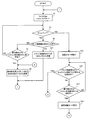
次に、図7および図8のフローチャートを参照して、本実施例の電子カメラ10におけるCPU20の動作について説明する。
Next, the operation of the
まず、電子カメラ10の電源がON状態となると、ステップS1で、タイマ20aのリセット&スタートを実行し、ステップS3へ進む。ステップS3では、タイマ20aがタイムアップして、タイムアップ状態を示すフラグが立っているか否かを判別する。ステップS3においてNOと判別すると、ステップS5へ進み、コマンド制御部24から指示の入力が有ったか否かを判別する。ステップS5においてNOと判別するとステップS7へ進み、操作部26またはリモコン受光部28から操作指示が有ったか否かを判別し、NOと判別するとステップS3へ戻る。ステップS7においてYESと判別するとステップS9へ進み、操作部26またはリモコン受光部28からの操作指示に応じた処理を実行し、ステップS1へ戻る。
First, when the power source of the
ステップS5において、YESと判別すると、ステップS11へ進み、コマンド制御部24からの指示に応じた処理を実行し、ステップS1へ戻る。
If YES is determined in the step S5, the process proceeds to a step S11, a process corresponding to an instruction from the
ステップS3において、YESと判別すると、ステップS13へ進み、電子カメラ10を通常稼動モードから一部のブロックの稼動を停止する省電力モードへ移行させる。そして、ステップS15へ進み、コマンド制御部24からテレビ受像機4へ出力させるためのサムネイル画像マルチ再生処理指示が有ったか否かを判別する。ステップS15においてNOと判別するとステップS17へ進み、操作部26またはリモコン受光部28から操作指示が有ったか否かを判別する。ステップS17において、NOであると判別するとステップS15へ戻り、YESであると判別するとステップS19へ進む。ステップS19では、電子カメラ10を一部の稼動を停止する省電力モードから通常稼動モードへ移行させ、ステップS9へ進む。
If YES is determined in step S3, the process proceeds to step S13, and the
ステップS15において、YESと判別すると、ステップS21へ進み、電子カメラ10を一部の稼動を停止する省電力モードから通常稼動モードへ移行させ、ステップS23へ進む。ステップS23では、外部メモリカード32に記憶されている静止画像ファイルおよび/または動画像ファイルから各ファイルのサムネイル画像圧縮データを読み出し、圧縮・伸張処理部22によりJPEG方式に従う伸張処理が施された各サムネイル画像データに基づいて、図5に示すように9枚分のサムネイルを配列させるサムネイル画像マルチ表示画面データを生成する。そして、ステップS25へ進み、TMDS信号線を通してHDMIインタフェース36からHDMI端子38を介して、テレビ受像機4へ、サムネイル画像マルチ表示画面データを出力し、ステップS1へ戻る。
If YES is determined in the step S15, the process proceeds to a step S21 so as to shift the
以上のように、本実施例によれば、電子カメラ10とテレビ受像機4がHDMIケーブル8で接続されており、かつ電子カメラ10が省電力モードにおいて、テレビ受像機用リモコン6のカメラ一覧ボタン62が押下されると、電子カメラ10が省電力モードから通常稼動モードへ移行し、かつテレビ受像機4に、電子カメラ10の外部メモリカード32に記憶されている静止画像ファイルおよび/または動画像ファイルの各サムネイル画像がマルチ表示されるため、使用者にとっては、簡単な操作ですぐに外部メモリカード20にどのような画像が記憶されているかを確認できるため、便利である。
As described above, according to this embodiment, when the
また、電子カメラ10に備えられたLCDモニタ34のよりも大きいテレビ受像機4のディスプレイにて、サムネイル画像がマルチ表示されるため、LCDモニタ34にて所望のサムネイル画像を検索するよりも、検索しやすく、利便性が高い。
In addition, since the thumbnail images are displayed in multiple on the display of the
また、本実施例の電子カメラ10とテレビ受像機4は、HDMI規格のインタフェースに準じたHDMIケーブル8で接続されており、非圧縮デジタル音声および映像を伝達することができ、高品質の音声および映像画質の劣化が生じないため、使用者は、常に鮮明な映像を見ることができる。そして、HDMI規格のインタフェースで互いに接続される電子機器が、現在急速に普及が始まっているため、汎用性が高い。
In addition, the
なお、本実施例の電子カメラ10では、撮像デバイスとしてCMOSイメージャ14aを採用したが、CCDイメージャでもよい。
In the
また、本実施例の電子カメラ10では、外部メモリカード32に静止画像ファイルおよび/または動画像ファイルが記憶される構成としたが、電子カメラ10内部に設けられたメモリでもよい。
In the
また、本実施例の電子カメラ10では、テレビ受像機4と接続されるインタフェースとしてHDMI規格のインタフェースを採用したが、他のインタフェースでも良い。
In the
また、本実施例の電子カメラ10は、電子カメラ10内のHDMI端子38を介して、直接テレビ受像機4とHDMIケーブル8にて接続される構成としたが、電子カメラ10とテレビ受像機4との間に電子カメラ10用のクレードルを介して、接続しても良い。
The
また、本実施例の電子カメラ10では、省電力モード状態において、HDMIインタフェース36、コマンド制御部24およびCPU20のみへ電力供給が行われているが、電子カメラ10の消費電力が、通常稼動モードに対して極力少ない節電状態となるような電力供給状態であれば、他のブロックに対しても電力供給が行われていても良い。
Further, in the
また、本実施例の電子カメラ10では、CPU20が電子カメラ10のほとんど全ての機能を制御しているとして説明したが、CPUは複数存在し、夫々のCPUが制御する機能が夫々異なるような構成でも良い。この構成における、省電力モード状態としては、HDMIインタフェース36、コマンド制御部24及びコマンド制御部24に接続されるCPUのみへ電力供給が行われる状態であっても良い。
Further, in the
また、本実施例の電子カメラ10では、コマンド制御部24がHDMIインタフェース36に接続され、テレビ受像機4からのコマンドを解析し、CPU20へ指示を出力しているが、CPU20がコマンド制御部24の機能を持っていても良い。その場合、HDMIインタフェース36とCPU20が接続され、コマンド解析をCPU20が実行することとなる。
In the
4 …テレビ受像機
6 …テレビ受像機用リモコン
8 …HDMIケーブル
10 …電子カメラ
12 …撮像レンズ
14 …CMOSイメージャユニット
18 …SDRAM
20 …CPU
20a …タイマ
22 …圧縮・伸張処理部
24 …コマンド制御部
26 …操作部
30 …カード制御部
32 …外部メモリカード
34 …LCDモニタ
36 …HDMIインタフェース
38 …HDMI端子
42 …バス
62 …カメラ一覧ボタン
4 ...
20 ... CPU
20a ...
Claims (5)
操作キーを備えるリモートコントローラからの指示に従って制御される外部電子機器と前記撮像装置本体とを接続するためのインタフェース部と、
前記外部電子機器から出力される前記リモートコントローラの前記操作キーの各々の操作に応じた指示に対応するコマンドを受け付けるコマンド受付手段と、
前記画像信号に基づいて該画像信号に対応する静止画または動画の縮小画に対応する縮小画像信号を生成する縮小画像信号生成手段と、
前記画像信号を画像ファイルとして記憶する記憶手段と、
前記記憶手段に記憶されている複数の画像ファイルに対応する複数の前記縮小画像信号を前記インタフェース部を介して前記外部電子機器へ出力する出力処理を実行する出力制御手段とを備え、
前記撮像装置は、少なくとも前記撮像手段または前記出力制御手段が稼働状態である第一モードと、前記撮像手段および前記出力制御手段を含む前記撮像装置本体の一部が非稼動状態である第二モードとを有し、
前記外部電子機器から出力されるコマンドは、前記撮像処理を要求する第1コマンドおよび前記出力処理を要求する第2コマンドを含み、
前記撮像装置が前記第一モードである場合には、前記コマンド受付手段は前記第1コマンドまたは前記第2コマンドを受け付け、前記撮像装置が前記第二モードである場合には、前記コマンド受付手段は前記第1コマンドと前記第2コマンドのうち前記第2コマンドのみを受け付けることを特徴とする、撮像装置。 An imaging apparatus including an imaging unit and a display for performing an imaging process for capturing an optical image of a subject and generating an image signal,
An interface unit for connecting an external electronic device controlled in accordance with an instruction from a remote controller having an operation key and the imaging apparatus body;
Command receiving means for receiving a command corresponding to an instruction corresponding to each operation of the operation key of the remote controller output from the external electronic device;
Reduced image signal generation means for generating a reduced image signal corresponding to a still image or a reduced image of a moving image corresponding to the image signal based on the image signal;
Storage means for storing the image signal as an image file;
Output control means for executing output processing for outputting a plurality of reduced image signals corresponding to a plurality of image files stored in the storage means to the external electronic device via the interface unit;
The imaging apparatus includes a first mode in which at least the imaging unit or the output control unit is in an operating state, and a second mode in which a part of the imaging apparatus main body including the imaging unit and the output control unit is in an inoperative state And
The command output from the external electronic device includes a first command that requests the imaging process and a second command that requests the output process,
When the imaging device is in the first mode, the command receiving unit receives the first command or the second command, and when the imaging device is in the second mode, the command receiving unit is An imaging apparatus that accepts only the second command of the first command and the second command .
前記外部出力制御手段によって出力される前記縮小画像信号はデジタル信号であり、
前記インタフェース部を介して出力される前記デジタル信号は前記表示手段に供給されることを特徴とする、請求項1または2に記載の撮像装置。 The external electronic device further includes display means,
The reduced image signal output by the external output control means is a digital signal,
The imaging apparatus according to claim 1, wherein the digital signal output via the interface unit is supplied to the display unit.
前記画像信号に基づいて該画像信号に対応する静止画または動画の縮小画に対応する縮小画像信号を生成する縮小画像信号生成手段と、
前記画像信号を画像ファイルとして記憶手段とを備える撮像装置と、
該撮像装置と接続される、操作キーを備えるリモートコントローラからの指示に従って制御される外部電子機器との間でデータ通信を行うデータ通信システムであって、
前記撮像装置は、
前記外部電子機器から出力される前記リモートコントローラの前記操作キーの各々の操作に応じた指示に対応するコマンドを受け付けるコマンド受付手段と、
前記記憶手段に記憶されている複数の画像ファイルに対応する複数の前記縮小画像信号を前記外部電子機器へ出力する出力処理を実行する出力制御手段とを備え、
少なくとも前記表示出力手段または前記出力制御手段が稼働状態である第一モードと、前記表示出力手段および前記出力制御手段を含む前記撮像装置本体の一部が非稼動状態である第二モードとを有し、
前記外部電子機器から発行されるコマンドは、前記撮像処理を要求する第1コマンドおよび前記出力処理を要求する第2コマンドを含み、
前記撮像装置が前記第一モードである場合には前記コマンド受付手段は前記第1コマンドまたは前記第2コマンドを受け付け、前記撮像装置が前記第二モードである場合には、前記コマンド受付手段は前記第1コマンドと前記第2コマンドのうち前記第2コマンドのみを受け付けることを特徴とする、データ通信システム。 Imaging means for capturing an optical image of a subject and generating an image signal;
Reduced image signal generation means for generating a reduced image signal corresponding to a still image or a reduced image of a moving image corresponding to the image signal based on the image signal;
An imaging device comprising a storage means as the image signal as an image file;
A data communication system that performs data communication with an external electronic device that is connected to the imaging device and controlled according to an instruction from a remote controller having an operation key,
The imaging device
Command receiving means for receiving a command corresponding to an instruction corresponding to each operation of the operation key of the remote controller output from the external electronic device;
Output control means for executing output processing for outputting a plurality of the reduced image signals corresponding to the plurality of image files stored in the storage means to the external electronic device;
A first mode in which at least the display output unit or the output control unit is in an operating state; and a second mode in which a part of the imaging apparatus main body including the display output unit and the output control unit is in an inoperative state. And
The commands issued from the external electronic device include a first command that requests the imaging process and a second command that requests the output process,
When the imaging apparatus is in the first mode, the command receiving means receives the first command or the second command, and when the imaging apparatus is in the second mode, the command receiving means is A data communication system, wherein only the second command is accepted among the first command and the second command .
前記画像信号に基づいて該画像信号に対応する静止画または動画の縮小画に対応する縮小画像信号を生成する縮小画像信号生成手段と、
前記画像信号を画像ファイルとして記憶手段とを備える撮像装置と、
該撮像装置と接続される、操作キーを備えるリモートコントローラからの指示に従って制御される外部電子機器との間でデータ通信を行うデータ通信方法であって、
前記外部電子機器から出力される前記リモートコントローラの前記操作キーの各々の操作に応じた指示に対応するコマンドを受け付けるコマンド受付ステップと、
前記記憶手段に記憶されている複数の画像ファイルに対応する複数の前記縮小画像信号を前記外部電子機器へ出力する出力処理を実行する出力制御ステップとを備え、
少なくとも前記表示出力ステップまたは前記外部出力制御ステップが実行可能状態である第一モードと、前記撮像手段および前記外部出力制御ステップを含む前記撮像装置本体の一部が実行不可能状態である第二モードとを有し、
前記外部電子機器から発行されるコマンドは、前記撮像処理を要求するを要求する第1コマンドおよび前記出力処理を要求する第2コマンドを含み、
前記撮像装置が前記第一モードである場合には前記コマンド受付ステップは前記第1コマンドまたは前記第2コマンドを受け付け、前記撮像装置が前記第二モードである場合には、前記コマンド受付ステップは前記第1コマンドと前記第2コマンドのうち前記第2コマンドのみを受け付けることを特徴とする、データ通信方法。 Imaging means for capturing an optical image of a subject and generating an image signal;
Reduced image signal generation means for generating a reduced image signal corresponding to a still image or a reduced image of a moving image corresponding to the image signal based on the image signal;
An imaging and storage means the image signal as an image file,
A data communication method for performing data communication with an external electronic device connected to the imaging device and controlled according to an instruction from a remote controller having an operation key,
A command receiving step for receiving a command corresponding to an instruction corresponding to each operation of the operation key of the remote controller output from the external electronic device;
An output control step for executing output processing for outputting a plurality of the reduced image signals corresponding to the plurality of image files stored in the storage means to the external electronic device,
A first mode in which at least the display output step or the external output control step is executable; and a second mode in which a part of the imaging apparatus main body including the imaging means and the external output control step is in an inexecutable state And
The commands issued from the external electronic device include a first command for requesting the imaging process and a second command for requesting the output process,
When the imaging device is in the first mode, the command receiving step receives the first command or the second command, and when the imaging device is in the second mode, the command receiving step is A data communication method characterized by receiving only the second command of the first command and the second command .
Priority Applications (3)
| Application Number | Priority Date | Filing Date | Title |
|---|---|---|---|
| JP2008160945A JP5094583B2 (en) | 2008-06-19 | 2008-06-19 | Imaging apparatus, data communication system, and data communication method |
| US12/487,482 US20090316017A1 (en) | 2008-06-19 | 2009-06-18 | Imaging apparatus, data communicating system, and data communicating method |
| CN200910166958A CN101635814A (en) | 2008-06-19 | 2009-06-18 | Imaging apparatus, data communicating system, and data communicating method |
Applications Claiming Priority (1)
| Application Number | Priority Date | Filing Date | Title |
|---|---|---|---|
| JP2008160945A JP5094583B2 (en) | 2008-06-19 | 2008-06-19 | Imaging apparatus, data communication system, and data communication method |
Publications (2)
| Publication Number | Publication Date |
|---|---|
| JP2010004297A JP2010004297A (en) | 2010-01-07 |
| JP5094583B2 true JP5094583B2 (en) | 2012-12-12 |
Family
ID=41430830
Family Applications (1)
| Application Number | Title | Priority Date | Filing Date |
|---|---|---|---|
| JP2008160945A Expired - Fee Related JP5094583B2 (en) | 2008-06-19 | 2008-06-19 | Imaging apparatus, data communication system, and data communication method |
Country Status (3)
| Country | Link |
|---|---|
| US (1) | US20090316017A1 (en) |
| JP (1) | JP5094583B2 (en) |
| CN (1) | CN101635814A (en) |
Families Citing this family (5)
| Publication number | Priority date | Publication date | Assignee | Title |
|---|---|---|---|---|
| JP2008089887A (en) * | 2006-09-29 | 2008-04-17 | Toshiba Corp | Video output device and display device |
| JP5501442B2 (en) * | 2010-03-09 | 2014-05-21 | キヤノン株式会社 | VIDEO DISPLAY DEVICE, VIDEO DISPLAY DEVICE CONTROL METHOD, VIDEO OUTPUT DEVICE, AND VIDEO OUTPUT DEVICE CONTROL METHOD |
| KR101952260B1 (en) * | 2012-04-03 | 2019-02-26 | 삼성전자주식회사 | Video display terminal and method for displaying a plurality of video thumbnail simultaneously |
| US9987184B2 (en) * | 2013-02-05 | 2018-06-05 | Valentin Borovinov | Systems, methods, and media for providing video of a burial memorial |
| JP7321685B2 (en) * | 2018-08-22 | 2023-08-07 | キヤノン株式会社 | Imaging device |
Family Cites Families (10)
| Publication number | Priority date | Publication date | Assignee | Title |
|---|---|---|---|---|
| US20030117499A1 (en) * | 2001-12-21 | 2003-06-26 | Bianchi Mark J. | Docking station that enables wireless remote control of a digital image capture device docked therein |
| JP4055059B2 (en) * | 2002-09-20 | 2008-03-05 | 株式会社リコー | Image forming apparatus |
| US20060044394A1 (en) * | 2004-08-24 | 2006-03-02 | Sony Corporation | Method and apparatus for a computer controlled digital camera |
| JP2006074255A (en) * | 2004-08-31 | 2006-03-16 | Kyocera Mita Corp | Image processing apparatus |
| JP4208805B2 (en) * | 2004-09-15 | 2009-01-14 | キヤノン株式会社 | Electronic device, control method thereof, and program |
| JP2007221239A (en) * | 2006-02-14 | 2007-08-30 | Canon Inc | Extended image processing system |
| JP2007221397A (en) * | 2006-02-16 | 2007-08-30 | Fujitsu General Ltd | Electronics device equipped with remote control receiving circuit |
| JP2007228049A (en) * | 2006-02-21 | 2007-09-06 | Pentax Corp | Imaging apparatus control unit and digital camera |
| EP2950528A1 (en) * | 2006-11-07 | 2015-12-02 | Sony Corporation | Video signal transmitting device |
| JP4829806B2 (en) * | 2007-01-30 | 2011-12-07 | キヤノン株式会社 | Data processing apparatus and computer program |
-
2008
- 2008-06-19 JP JP2008160945A patent/JP5094583B2/en not_active Expired - Fee Related
-
2009
- 2009-06-18 US US12/487,482 patent/US20090316017A1/en not_active Abandoned
- 2009-06-18 CN CN200910166958A patent/CN101635814A/en active Pending
Also Published As
| Publication number | Publication date |
|---|---|
| JP2010004297A (en) | 2010-01-07 |
| CN101635814A (en) | 2010-01-27 |
| US20090316017A1 (en) | 2009-12-24 |
Similar Documents
| Publication | Publication Date | Title |
|---|---|---|
| US8564723B2 (en) | Communication system, communication method, video output apparatus and video input apparatus | |
| RU2363114C1 (en) | Image playback device and control method | |
| US8581994B2 (en) | Photographing apparatus | |
| US8687119B2 (en) | Video display apparatus and control method thereof, and video output apparatus and control method thereof | |
| US20080320395A1 (en) | Electronic apparatus, an imaging apparatus, a display control method for the same and a program which allows a computer to execute the method | |
| JP4945961B2 (en) | Imaging device | |
| JP2010177980A (en) | Imaging apparatus and imaging method | |
| JP5094583B2 (en) | Imaging apparatus, data communication system, and data communication method | |
| JP6362116B2 (en) | Display device, control method therefor, program, and storage medium | |
| US8310558B2 (en) | Imaging apparatus having a recording function of a still image and a moving image and displaying a through image | |
| JP2009094663A (en) | Imaging apparatus | |
| US9323496B2 (en) | Electronic device capable of transmitting an image | |
| US9263001B2 (en) | Display control device | |
| JP4369263B2 (en) | Digital camera and image signal generation method | |
| US20160156843A1 (en) | Image processing apparatus | |
| JP4871819B2 (en) | Image storage system, image storage device, and control method of image storage device | |
| JP2013090243A (en) | Image output device and image display device | |
| KR20060057058A (en) | Display apparatus capable of setting optimized external input and method thereof | |
| KR101102388B1 (en) | Apparatus and method capturing still image in digital broadcasting receiver | |
| JP2005080042A (en) | Digital camera | |
| JP2005080041A (en) | Digital camera | |
| JP2009159194A (en) | Image pickup device | |
| JP2019110423A (en) | Imaging device, control method, and program | |
| JP2019204032A (en) | Display | |
| JP2017022546A (en) | Communication device |
Legal Events
| Date | Code | Title | Description |
|---|---|---|---|
| A621 | Written request for application examination |
Free format text: JAPANESE INTERMEDIATE CODE: A621 Effective date: 20110527 |
|
| RD02 | Notification of acceptance of power of attorney |
Free format text: JAPANESE INTERMEDIATE CODE: A7422 Effective date: 20111117 |
|
| RD04 | Notification of resignation of power of attorney |
Free format text: JAPANESE INTERMEDIATE CODE: A7424 Effective date: 20111130 |
|
| A977 | Report on retrieval |
Free format text: JAPANESE INTERMEDIATE CODE: A971007 Effective date: 20120515 |
|
| A131 | Notification of reasons for refusal |
Free format text: JAPANESE INTERMEDIATE CODE: A131 Effective date: 20120612 |
|
| A521 | Request for written amendment filed |
Free format text: JAPANESE INTERMEDIATE CODE: A523 Effective date: 20120802 |
|
| TRDD | Decision of grant or rejection written | ||
| A01 | Written decision to grant a patent or to grant a registration (utility model) |
Free format text: JAPANESE INTERMEDIATE CODE: A01 Effective date: 20120821 |
|
| A01 | Written decision to grant a patent or to grant a registration (utility model) |
Free format text: JAPANESE INTERMEDIATE CODE: A01 |
|
| A61 | First payment of annual fees (during grant procedure) |
Free format text: JAPANESE INTERMEDIATE CODE: A61 Effective date: 20120918 |
|
| FPAY | Renewal fee payment (event date is renewal date of database) |
Free format text: PAYMENT UNTIL: 20150928 Year of fee payment: 3 |
|
| FPAY | Renewal fee payment (event date is renewal date of database) |
Free format text: PAYMENT UNTIL: 20150928 Year of fee payment: 3 |
|
| S111 | Request for change of ownership or part of ownership |
Free format text: JAPANESE INTERMEDIATE CODE: R313113 |
|
| FPAY | Renewal fee payment (event date is renewal date of database) |
Free format text: PAYMENT UNTIL: 20150928 Year of fee payment: 3 |
|
| R350 | Written notification of registration of transfer |
Free format text: JAPANESE INTERMEDIATE CODE: R350 |
|
| LAPS | Cancellation because of no payment of annual fees |