JP5090963B2 - Control device and control method for damping force variable damper - Google Patents
Control device and control method for damping force variable damper Download PDFInfo
- Publication number
- JP5090963B2 JP5090963B2 JP2008042880A JP2008042880A JP5090963B2 JP 5090963 B2 JP5090963 B2 JP 5090963B2 JP 2008042880 A JP2008042880 A JP 2008042880A JP 2008042880 A JP2008042880 A JP 2008042880A JP 5090963 B2 JP5090963 B2 JP 5090963B2
- Authority
- JP
- Japan
- Prior art keywords
- damping force
- roll
- turning
- vehicle
- target damping
- Prior art date
- Legal status (The legal status is an assumption and is not a legal conclusion. Google has not performed a legal analysis and makes no representation as to the accuracy of the status listed.)
- Expired - Fee Related
Links
Images


Description
本発明は、減衰力可変ダンパの制御装置および制御方法に係り、詳しくは、旋回走行時における乗り心地の向上やタイヤ横滑りの抑制等を実現する技術に関する。 The present invention relates to a control device and a control method for a damping force variable damper, and more particularly to a technique for improving riding comfort and suppressing tire skidding during turning.
4輪自動車のサスペンションに用いられる筒型ダンパとして、乗り心地や操縦安定性の向上を図るべく、減衰力を段階的あるいは無段階に可変制御できる減衰力可変型のものが種々開発されている。減衰力可変ダンパ(以下、単にダンパと記す)を装着した自動車では、その走行状態に応じてダンパの減衰力を可変制御することにより、操縦安定性や乗り心地の向上を図ることが可能となる。例えば、自動車の旋回走行時には横方向運動に伴う慣性力(横加速度)によって車体が左右方向にロール動するが、横加速度の微分値に応じて第1のロール目標減衰力を算出する一方で、ヨーレイトの2階微分値に応じて第2のロール目標減衰力を算出し、これら第1,第2のロール目標減衰力のうちでその絶対値が大きい方に基づいて減衰力制御を行うものが提案されている(特許文献1参照)。また、車体の前後加速度の微分値または横加速度の微分値に基づきロール目標減衰力を設定した後、このロール目標減衰力をばね下速度あるいはダンパの荷重によって補正するものが提案されている(特許文献2参照)。 As a cylindrical damper used for a suspension of a four-wheeled vehicle, various types of damping force variable types capable of variably controlling the damping force stepwise or steplessly have been developed in order to improve ride comfort and handling stability. In an automobile equipped with a variable damping force damper (hereinafter simply referred to as a damper), it is possible to improve steering stability and ride comfort by variably controlling the damping force of the damper according to its running state. . For example, when the vehicle turns, the vehicle body rolls in the left-right direction due to inertial force (lateral acceleration) that accompanies lateral movement, while calculating the first roll target damping force according to the differential value of the lateral acceleration, The second roll target damping force is calculated according to the second-order differential value of the yaw rate, and the damping force control is performed based on the larger one of the first and second roll target damping forces. It has been proposed (see Patent Document 1). Further, there has been proposed a method in which a roll target damping force is set based on a differential value of longitudinal acceleration or lateral acceleration of a vehicle body, and then the roll target damping force is corrected by an unsprung speed or a damper load (patent) Reference 2).
しかしながら、特許文献1,2の方法では、全車輪のロール目標減衰力を同一の値としていることに起因して、乗り心地や操縦安定性の点で以下に述べるような問題が生じていた。すなわち、自動車の旋回走行時おいて全車輪のロール目標減衰力が高く設定されると、路面からの突き上げ(車輪の上下動がサスペンションを介して車体へ伝達される現象)をいなし難くなって乗り心地が低下する。また、全車輪のロール目標減衰力が高く設定された場合、車輪間での荷重の移動速度が高くなるため、図13に示すように、旋回外輪3fr,3rr側に過渡的に大きな荷重Lfr,Lrrが掛かる。そのため、路面の摩擦係数が小さい場合等に荷重が増加した旋回外輪3fr,3rrのタイヤが発生するコーナリングパワーが飽和することで、旋回内輪3fl,3rlのタイヤと旋回外輪3fr,3rrのタイヤとの平均コーナリングパワーが減少してしまい、タイヤの横滑りが発生する虞があった。なお、図14の荷重−コーナリングパワー線図に示すように、コーナリングパワーは荷重に対して上向きに凸な変化を示すため、旋回内輪側の荷重と旋回外輪側の荷重との差が小さいほど、高い平均コーナリングパワーが得られる。 However, the methods of Patent Documents 1 and 2 have the following problems in terms of ride comfort and handling stability because the roll target damping force of all the wheels is set to the same value. That is, if the roll target damping force of all the wheels is set high during turning of the automobile, it becomes difficult to push up from the road surface (a phenomenon in which the vertical movement of the wheels is transmitted to the vehicle body via the suspension). Ride comfort is reduced. Further, when the roll target damping force of all the wheels is set to be high, the moving speed of the load between the wheels becomes high. Therefore, as shown in FIG. 13, a transiently large load Lfr, Lrr is applied. Therefore, when the cornering power generated by the tires of the turning outer wheels 3fr and 3rr with increased load is saturated when the friction coefficient of the road surface is small, the tires of the turning inner wheels 3fl and 3rl and the tires of the turning outer wheels 3fr and 3rr are saturated. There was a risk that the average cornering power would decrease and the skid of the tire would occur. In addition, as shown in the load-cornering power diagram of FIG. 14, the cornering power shows an upwardly convex change with respect to the load. Therefore, the smaller the difference between the load on the turning inner ring side and the load on the turning outer ring side, High average cornering power is obtained.
本発明は、このような背景に鑑みなされたもので、旋回走行時における乗り心地の向上やタイヤ横滑りの抑制等を実現する減衰力可変ダンパの制御装置および制御方法を提供することを目的とする。 The present invention has been made in view of such a background, and an object of the present invention is to provide a control device and a control method for a damping force variable damper that realizes improvement in riding comfort and suppression of tire skidding during turning. .
第1の発明は、車体と各車輪との間に減衰力可変ダンパがそれぞれ介装された車両に搭載され、当該減衰力可変ダンパの減衰力制御に供される制御装置であって、前記車両の旋回状態量を検出する旋回状態量検出手段と、前記旋回状態量検出手段の検出結果に基づき、各減衰力可変ダンパのロール目標減衰力を個別に設定するロール目標減衰力設定手段とを備え、前記ロール目標減衰力設定手段は、前記車両が旋回走行状態にある場合、旋回内側前輪側以外のロール目標減衰力を低下させることを特徴とする。 A first invention is a control device mounted on a vehicle in which a damping force variable damper is interposed between a vehicle body and each wheel, and used for damping force control of the damping force variable damper. And a roll target damping force setting unit for individually setting a roll target damping force of each damping force variable damper based on a detection result of the turning state amount detection unit. The roll target damping force setting means reduces the roll target damping force other than the side of the turning inner front wheel when the vehicle is in a turning traveling state.
また、第2の発明は、第1の発明に係る減衰力可変ダンパの制御装置において、各車輪の滑り状態を検出する車輪滑り状態検出手段を更に備え、前記ロール目標減衰力設定手段は、前記車輪滑り状態検出手段によっていずれかの車輪が滑っていることが検出された場合にのみ、旋回内側前輪側以外のロール目標減衰力を低下させることを特徴とする。 The second aspect of the invention is the damping force variable damper control device according to the first aspect of the invention, further comprising wheel slip state detecting means for detecting a slip state of each wheel, wherein the roll target damping force setting means is the Only when it is detected by the wheel slip state detecting means that one of the wheels is slipping, the roll target damping force other than that on the turning inner front wheel side is reduced.
また、第3の発明は、車両の懸架に供される減衰力可変ダンパの制御方法であって、前記車両の旋回状態量を検出する処理と、前記旋回状態量に基づき、前記減衰力可変ダンパのロール目標減衰力を設定する処理と、前記車両が旋回走行状態にあるか否かを判定する処理と、前記車両が旋回走行状態にあると判定した場合、旋回内側前輪側以外のロール目標減衰力を低下させる処理とを含むことを特徴とする。 The third invention is a control method of the variable damping force damper which is subjected to the suspension of the vehicle, the processing for detecting the turning state of the vehicle, based on the turning state quantity, the damping force variable damper A roll target damping force other than the inside wheel on the inside of the turn when it is determined that the vehicle is in a turning traveling state, and a process for determining whether or not the vehicle is in a turning traveling state. And a process for reducing the force.
第1の発明によれば、旋回走行時において、旋回内側前輪以外のロール目標減衰力を低下させるようにしたため、路面からの突き上げがいなされやすくなり、良好な乗り心地を確保することができる。また、過渡時における旋回外側車輪の荷重と旋回内側車輪の荷重との差が小さくなるため、より大きな平均コーナリングパワーが得られてタイヤの横滑りを効果的に抑制することができる。また、第2の発明によれば、旋回内側前輪以外のロール目標減衰力を車輪がスリップしたときにのみ低下させるため、乗り心地をより向上させることができる。また、第3の発明によれば、旋回走行時において、旋回内側前輪以外のロール目標減衰力を低下させるようにしたため、路面からの突き上げがいなされやすくなり、良好な乗り心地を確保することができる。また、過渡時における旋回外側車輪の荷重と旋回内側車輪の荷重との差が小さくなるため、より大きな平均コーナリングパワーが得られてタイヤの横滑りを効果的に抑制することができる。 According to the first aspect of the invention, since the roll target damping force other than the turning inner front wheel is reduced during turning, it is easy to push up from the road surface, and a good riding comfort can be ensured. Further, since the difference between the load on the turning outer wheel and the load on the turning inner wheel at the time of transition is reduced, a larger average cornering power can be obtained and the side skid of the tire can be effectively suppressed. In addition, according to the second invention, the roll target damping force other than the turning inner front wheel is reduced only when the wheel slips, so that the riding comfort can be further improved. In addition, according to the third aspect of the present invention, the roll target damping force other than the turning inner front wheel is reduced during turning, so that it is easy to push up from the road surface, and good riding comfort can be ensured. . Further, since the difference between the load on the turning outer wheel and the load on the turning inner wheel at the time of transition is reduced, a larger average cornering power can be obtained and the side skid of the tire can be effectively suppressed.
以下、本発明を4輪自動車に適用した2つの実施形態について、図面を参照して詳細に説明する。 Hereinafter, two embodiments in which the present invention is applied to a four-wheeled vehicle will be described in detail with reference to the drawings.
[第1実施形態]
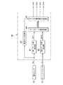
図1は第1実施形態に係る4輪自動車の概略構成図であり、図2は第1実施形態に係るダンパの縦断面図であり、図3は第1実施形態に係る減衰力制御装置の概略構成を示すブロック図であり、図4は第1実施形態に係るロール演算制御部の概略構成を示すブロック図である。
[First Embodiment]
FIG. 1 is a schematic configuration diagram of a four-wheel vehicle according to the first embodiment, FIG. 2 is a longitudinal sectional view of a damper according to the first embodiment, and FIG. 3 is a diagram of the damping force control device according to the first embodiment. FIG. 4 is a block diagram illustrating a schematic configuration, and FIG. 4 is a block diagram illustrating a schematic configuration of a roll calculation control unit according to the first embodiment.
<自動車の概略構成>
先ず、図1を参照して、第1実施形態に係る自動車の概略構成について説明する。説明にあたり、4本の車輪やそれらに対応してする部材(タイヤやサスペンション等)については、それぞれ符号(数字)に前後左右を示す添字を付して、車輪3fl(左前)、車輪3fr(右前)、車輪3rl(左後)、車輪3rr(右後)等と記すとともに、総称する場合には添字の無い符号を用いて車輪3等と記す。
<Schematic configuration of automobile>
First, a schematic configuration of the automobile according to the first embodiment will be described with reference to FIG. In the description, for the four wheels and corresponding members (tires, suspensions, etc.), suffixes indicating front, rear, left and right are attached to the reference numerals (numbers), respectively, so that the wheels 3fl (front left) and wheels 3fr (front right) ), Wheel 3rl (rear left), wheel 3rr (rear right), and the like, and when referring generically, it is denoted as wheel 3 or the like using a symbol without a suffix.
図1に示すように、自動車(車両)Vの車体1にはタイヤ2が装着された車輪3が前後左右に設置されており、これら各車輪3がサスペンションアーム4や、スプリング5、減衰力可変式ダンパ(以下、単にダンパと記す)6等からなるサスペンション7によって車体1に懸架されている。自動車Vには、各種の制御に供されるECU(Electronic Control Unit)8の他、車速センサ9や横Gセンサ10、前後Gセンサ11、ヨーレイトセンサ12等が車体1の適所に設置されている。また、自動車Vには、上下Gセンサ(ばね上加速度検出手段)13と、ストロークセンサ(状態量検出手段)14と、車輪速センサ15とが各車輪3fl〜3rrごとに設置されている。
As shown in FIG. 1, a vehicle body 1 of an automobile (vehicle) V has wheels 3 with tires 2 mounted on the front, rear, left and right thereof. These wheels 3 are each provided with a suspension arm 4, a spring 5, and a variable damping force. It is suspended from the vehicle body 1 by a suspension 7 composed of a type damper (hereinafter simply referred to as a damper) 6 or the like. In the vehicle V, in addition to an ECU (Electronic Control Unit) 8 used for various controls, a
ECU8は、マイクロコンピュータやROM、RAM、周辺回路、入出力インタフェース、各種ドライバ等から構成されており、通信回線(第1実施形態では、CAN(Controller Area Network))を介して、各車輪3のダンパ6や各センサ9〜15と接続されている。
The ECU 8 includes a microcomputer, a ROM, a RAM, a peripheral circuit, an input / output interface, various drivers, and the like. Each of the wheels 3 is connected via a communication line (CAN (Controller Area Network) in the first embodiment). The
<ダンパ>
図2に示すように、第1実施形態のダンパ6は、モノチューブ式(ド・カルボン式)であり、MRF(Magneto-Rheological Fluid:磁気粘性流体)が充填された円筒状のシリンダ22と、このシリンダ22に対して軸方向に摺動するピストンロッド23と、ピストンロッド23の先端に装着されてシリンダ22内を上部油室24と下部油室25とに区画するピストン26と、シリンダ22の下部に高圧ガス室27を画成するフリーピストン28と、ピストンロッド23等への塵埃の付着を防ぐカバー29と、フルバウンド時における緩衝を行うバンプストップ30とを主要構成要素としている。
<Damper>
As shown in FIG. 2, the
シリンダ22は、下端のアイピース22aに嵌挿されたボルト31を介して、車輪側部材であるサスペンションアーム4の上面に連結されている。また、ピストンロッド23は、上下一対のラバーブッシュ32とナット33とを介して、その上端のスタッド23aが車体側部材であるダンパベース(ホイールハウス上部)34に連結されている。
The
ピストン26には、上部油室24と下部油室25とを連通する連通路41と、この連通路41の内側に位置するMLVコイル42とが設けられている。ECU8からMLVコイル42に電流が供給されると、連通路41を流通するMRFに磁界が印可されて強磁性微粒子が鎖状のクラスタを形成する。これにより、連通路41を通過するMRFの見かけ上の粘度(以下、単に粘度と記す)が上昇し、ダンパ6の減衰力が増大する。
The
<減衰力制御装置の概略構成>
図3に示すように、ECU8には、ダンパ6の制御を行う減衰力制御装置50が内装されている。減衰力制御装置50は、上述した各センサ9〜15が接続する入力インタフェース51と、各センサ9〜15の検出信号から得られたロールモーメントやピッチモーメント、ばね上速度等に基づき各ダンパ6の目標減衰力を設定する減衰力設定部52と、減衰力設定部52から入力した目標減衰力とストロークセンサ14から入力したストローク速度Ssとに応じて各ダンパ6(MLVコイル42)への駆動電流を生成する駆動電流生成部53と、駆動電流生成部53が生成した駆動電流を各ダンパ6に出力する出力インタフェース54とから構成されている。なお、減衰力設定部52には、スカイフック制御に供されるスカイフック演算制御部55や、ロール制御に供されるロール演算制御部56、ピッチ制御に供されるピッチ演算制御部57等が収容されている。
<Schematic configuration of damping force control device>
As shown in FIG. 3, the
<ロール演算制御部>
図4に示すように、ロール演算制御部56は、横加速度Gyに基づいて第1ベース値Drb1を設定する第1ベース値設定部61と、ヨーレイトγに基づいて第2ベース値Drb2を設定する第2ベース値設定部62と、第1ベース値Drb1と第2ベース値Drb2とのうち絶対値の大きい方をロール減衰力ベース値Drbaseとして選択/設定するロールベース値設定部63と、横加速度Gyに基づいて旋回方向を判定する旋回方向判定部64と、ロールベース値設定部63の設定結果と旋回方向判定部64の判定結果とに基づいて各車輪3に対するロール目標減衰力Drtfl〜Drtrrを設定/出力するロール目標減衰力設定部65を備えている。
<Roll calculation control unit>
As shown in FIG. 4, the roll
≪第1実施形態の作用≫
<減衰力制御>
自動車Vが走行を開始すると、減衰力制御装置50は、所定の処理インターバル(例えば、10ms)をもって、図5のフローチャートにその手順を示す減衰力制御を繰り返し実行する。減衰力制御を開始すると、減衰力制御装置50は、図5のステップS1で、横Gセンサ10、前後Gセンサ11、および上下Gセンサ13から得られた車体1の各加速度や、車速センサ(図示せず)から入力した車速等に基づき自動車Vの運動状態を判定する。次に、減衰力制御装置50は、自動車Vの運動状態に基づき、ステップS2でスカイフック目標減衰力Dshtgtを設定し、ステップS3で各ダンパ6のロール目標減衰力Drtgt(Drtfl〜Drtrr)をそれぞれ設定し、ステップS4でピッチ目標減衰力Dptgtを設定する。
<< Operation of First Embodiment >>
<Damping force control>
When the vehicle V starts traveling, the damping
次に、減衰力制御装置50は、ステップS5で各ダンパ6のストローク速度Ssが正の値であるか否かを判定し、この判定がYesであった場合(すなわち、ダンパ6が伸び側に作動している場合)、ステップS6で3つの目標減衰力Dshtgt,Drtgt,Dptgtのうち値が最も大きいものを目標減衰力Dtgtとして採用する。また、減衰力制御装置50は、ステップS5の判定がNoであった場合(すなわち、ダンパ6が縮み側に作動している場合)、ステップS7で3つの目標減衰力Dshtgt,Drtgt,Dptgtのうち値が最も小さいものを目標減衰力Dtgtとして採用する。
Next, the damping
ステップS6またはステップS7で目標減衰力値Dtgtを決定すると、減衰力制御装置50は、ステップS8で図6の目標電流マップから目標減衰力Dtgtおよびストローク速度Ssに応じた目標電流Itgtを検索/設定した後、ステップS9で各ダンパ6のMLVコイル46に対して駆動電流を出力する。
When the target damping force value Dtgt is determined in step S6 or step S7, the damping
<ロール目標減衰力設定処理>
上述した減衰力制御と並行して、減衰力制御装置50内のロール演算制御部56は、所定の処理インターバルをもって、図7のフローチャートにその手順を示すロール目標減衰力設定処理を繰り返し実行する。ロール目標値設定処理を開始すると、ロール演算制御部56は、図7のステップS21で、横Gセンサ10から入力した横加速度Gyの微分値(以下、横加速度微分値と記す)Gy’を算出し、ステップS22で、図8の横加速度−減衰力マップを用いて、第1ベース値Drb1を検索/設定する。
<Roll target damping force setting process>
In parallel with the damping force control described above, the roll
次に、ロール演算制御部56は、ステップS23で、ヨーレイトセンサ12から入力したヨーレイトγを2階微分してヨーレイト2階微分値γ”(車軸位置の横加速度)を算出した後、ステップS24で、図9のヨーレイト−減衰力マップから第2ベース値Drb2を検索/設定する。次に、ロール演算制御部56は、ステップS25で、第1ベース値Drb1と第2ベース値Drb2とを比較し、絶対値の大きい方をロール減衰力ベース値Drbaseに設定する。
Next, in step S23, the roll
ステップS25でロール減衰力ベース値Drbaseを設定すると、ロール演算制御部56は、横加速度Gyに基づき、ステップS26で現在の旋回方向が左であるか否かを判定する。そして、ロール演算制御部56は、ステップS26の判定がYesであれば、ステップS27で、ロール減衰力ベース値Drbaseをそのまま旋回内側前輪(左前輪3fl)側に対するロール目標減衰力Drtflとし、ステップS28で、所定の低減係数Ki(例えば、0.1〜0.2)をロール減衰力ベース値Drbaseに乗じた値を他の車輪3fr〜3rr側に対するロール目標減衰力Drtfr〜Drtrrとした後、ステップS29で各ロール目標減衰力Drtfl〜Drtrrを出力する。
When the roll damping force base value Drbase is set in step S25, the roll
また、ステップS26の判定がNoであれば、ロール演算制御部56は、ステップS30で、ロール減衰力ベース値Drbaseをそのまま旋回内側前輪(右前輪3fr)側に対するロール目標減衰力Drtfrとし、ステップS31で、低減係数Ki(例えば、0.1〜0.2)をロール減衰力ベース値Drbaseに乗じた値を他の車輪3fl,3rl,3rr側に対するロール目標減衰力Drtfl,Drtrl,Drtrrとした後、ステップS29で各ロール目標減衰力Drtfl〜Drtrrを出力する。
If the determination in step S26 is No, the roll
本実施形態では、旋回走行時において、左前輪3fl側のダンパ6fl(あるいは、右前輪3fr側のダンパ6fr)以外のロール目標減衰力を低減させるようにしたため、路面からの突き上げがいなされやすくなり、良好な乗り心地を確保することができた。また、左旋回走行の場合を例にすると、図10に示すように、過渡時における旋回外側車輪3fr,3rrの荷重Lfr,Lrrと旋回内側車輪3fl,3rlの荷重Lfl,Lrlとの差が小さくなるため、前述の荷重−コーナリングパワー線図(図14)から判るように、より大きな平均コーナリングパワーが得られ、タイヤ2の横滑りを効果的に抑制することができる。 In the present embodiment, the roll target damping force other than the damper 6fl on the left front wheel 3fl side (or the damper 6fr on the right front wheel 3fr side) is reduced during cornering, so that it is easy to push up from the road surface. A good ride was secured. Further, taking the case of left turn as an example, as shown in FIG. 10, the difference between the loads Lfr, Lrr of the turning outer wheels 3fr, 3rr and the loads Lfl, Lrr of the turning inner wheels 3fl, 3rl at the time of transition is small. Therefore, as can be seen from the aforementioned load-cornering power diagram (FIG. 14), a larger average cornering power can be obtained, and the side slip of the tire 2 can be effectively suppressed.
[第2実施形態]
図11は、第2実施形態に係るロール演算制御部の概略構成を示すブロック図である。第2実施形態は、自動車や減衰力制御装置の構成を始め、減衰力制御の手順等も第1実施形態と同一であるため、重複する説明は省略する。
[Second Embodiment]
FIG. 11 is a block diagram illustrating a schematic configuration of a roll calculation control unit according to the second embodiment. In the second embodiment, the configuration of the automobile and the damping force control device, the damping force control procedure, and the like are the same as those in the first embodiment, and therefore, a duplicate description is omitted.
図11に示すように、第2実施形態のロール演算制御部56も上述した第1実施形態と略同様の構成を採っているが、各車輪3の車輪速センサ15からの車輪速vhに基づいてタイヤ2のスリップを判定するスリップ判定部66を備え、ロール目標減衰力設定部65がこのスリップ判定部66の判定結果も用いてロール目標減衰力の設定を行う点が異なっている。
As shown in FIG. 11, the roll
<ロール目標減衰力設定処理>
前述した減衰力制御(図5)と並行して、ロール演算制御部56は、所定の処理インターバルをもって、図12のフローチャートにその手順を示すロール目標減衰力設定処理を繰り返し実行する。ロール目標値設定処理を開始すると、ロール演算制御部56は、図12のステップS41で、横Gセンサ10から入力した横加速度Gyの微分値(以下、横加速度微分値と記す)Gy’を算出し、ステップS42で、図8の横加速度−減衰力マップを用いて、第1ベース値Drb1を検索/設定する。
<Roll target damping force setting process>
In parallel with the above-described damping force control (FIG. 5), the roll
次に、ロール演算制御部56は、ステップS43で、ヨーレイトセンサ12から入力したヨーレイトγを2階微分してヨーレイト2階微分値γ”(車軸位置の横加速度)を算出した後、ステップS44で、図9のヨーレイト−減衰力マップから第2ベース値Drb2を検索/設定する。次に、ロール演算制御部56は、ステップS45で、第1ロール減衰力ベース値Dbr1と第2ベース値Drb2とを比較し、絶対値の大きい方をロール減衰力ベース値Drbaseに設定する。
Next, in step S43, the roll
ステップS45でロール減衰力ベース値Drbaseを設定すると、ロール演算制御部56は、ステップS46で、各車輪3の車輪速vhfl〜vhrrを微分して車輪加速度vhfl’〜vhrr’を算出する。次に、ロール演算制御部56は、ステップS47で、これら車輪加速度vhfl’〜vhrr’のいずれかが所定のスリップ判定閾値vh’th(例えば、2.0G)を超えたか否かを判定する。そして、ステップS47の判定がNoであれば、ロール演算制御部56は、ステップS48でロール減衰力ベース値Drbaseをそのまま各車輪3のダンパ6に対するロール目標減衰力Drtfl〜Drtrrとし、ステップS49で各ロール目標減衰力Drtfl〜Drtrrを出力する。
When the roll damping force base value Drbase is set in step S45, the roll
一方、いずれかの車輪3のタイヤ2がスリップし、ステップS47の判定がYesになると、ロール演算制御部56は、横加速度Gyに基づき、ステップS50で現在の走行状態が左旋回走行であるか否かを判定する。そして、ステップS50の判定がYesであれば、ロール演算制御部56は、ステップS51で、ロール減衰力ベース値Drbaseをそのまま旋回内側前輪(左前輪3fl)側に対するロール目標減衰力Drtflとし、ステップS52で、他の車輪3fr〜3rr側に対するロール目標減衰力Drtfr〜Drtrrを0とする。しかる後、ロール演算制御部56は、ステップS49で各ロール目標減衰力Drtfl〜Drtrrを出力する。
On the other hand, if the tire 2 of any of the wheels 3 slips and the determination in step S47 becomes Yes, the roll
また一方、ステップS50の判定がNoであれば、ロール演算制御部56は、ステップS53で、ロール減衰力ベース値Drbaseをそのまま旋回内側前輪(右前輪3fr)側に対するロール目標減衰力Drtfrとし、ステップS54で、他の車輪3fl,3rl,3rr側に対するロール目標減衰力Drtfl,Drtrl,Drtrrを0とする。しかる後、ロール演算制御部56は、ステップS49で各ロール目標減衰力Drtfl〜Drtrrを出力する。
On the other hand, if the determination in step S50 is No, the roll
第2実施形態の作用・効果も上述した第1実施形態と略同様であるが、タイヤ2がスリップしたときにのみ旋回内側前輪側以外のロール目標減衰力を0とするようにしたため、乗り心地をより向上させることができる。 The operations and effects of the second embodiment are also substantially the same as those of the first embodiment described above, but the roll target damping force other than the turning inner front wheel side is set to 0 only when the tire 2 slips. Can be further improved.
以上で具体的実施形態の説明を終えるが、本発明の態様は上記実施形態に限られるものではない。例えば、旋回走行時の減衰力制御(ステップS6,S7)において、3つの目標減衰力から絶対値が最も小さいものを旋回内側前輪以外の目標減衰力として選択(ローセレクト)するようにしてもよく、その場合にも第1実施形態と略同様の効果を得ることができる。その他、本発明の趣旨を逸脱しない範囲であれば、自動車や制御装置の具体的構成、制御の具体的手順等についても適宜変更可能である。 Although description of specific embodiment is finished above, the aspect of the present invention is not limited to the above embodiment. For example, in damping force control during turning (steps S6 and S7), the one having the smallest absolute value among the three target damping forces may be selected (low selected) as the target damping force other than the turning front wheels. In this case, substantially the same effect as that of the first embodiment can be obtained. In addition, as long as it does not deviate from the gist of the present invention, the specific configuration of the automobile and the control device, the specific procedure of control, and the like can be appropriately changed.
1 車体
2 タイヤ
3 車輪
6 ダンパ
8 ECU
10 横Gセンサ(旋回状態量検出手段)
12 ヨーレイトセンサ(旋回状態量検出手段)
15 車輪速センサ
50 減衰力制御装置
56 ロール演算制御部
61 第1ベース値設定部
62 第2ベース値設定部
63 ロールベース値設定部
64 旋回方向判定部
65 ロール目標減衰力設定部(ロール目標減衰力設定手段)
66 スリップ判定部(車輪滑り状態検出手段)
V 自動車
1 Body 2 Tire 3
10 Lateral G sensor (turning state quantity detection means)
12 Yaw rate sensor (turning state quantity detection means)
DESCRIPTION OF
66 Slip judgment part (wheel slip state detection means)
V car
Claims (3)
前記車両の旋回状態量を検出する旋回状態量検出手段と、
前記旋回状態量検出手段の検出結果に基づき、各減衰力可変ダンパのロール目標減衰力を個別に設定するロール目標減衰力設定手段とを備え、
前記ロール目標減衰力設定手段は、前記車両が旋回走行状態にある場合、旋回内側前輪側以外のロール目標減衰力を低下させることを特徴とする減衰力可変ダンパの制御装置。 A control device mounted on a vehicle in which a damping force variable damper is interposed between a vehicle body and each wheel, and used for damping force control of the damping force variable damper,
A turning state amount detecting means for detecting a turning state amount of the vehicle;
Roll target damping force setting means for individually setting the roll target damping force of each damping force variable damper based on the detection result of the turning state quantity detecting means,
The roll target damping force setting means reduces the roll target damping force on the other side than the front inner wheel side when the vehicle is in a turning running state.
前記ロール目標減衰力設定手段は、前記車輪滑り状態検出手段によっていずれかの車輪が滑っていることが検出された場合にのみ、旋回内側前輪側以外のロール目標減衰力を低下させることを特徴とする、請求項1に記載された減衰力可変ダンパの制御装置。 Wheel slip state detecting means for detecting the slip state of each wheel is further provided,
The roll target damping force setting means reduces the roll target damping force other than that on the turning inner front wheel side only when it is detected by the wheel slip state detection means that any of the wheels is slipping. The damping force variable damper control device according to claim 1.
前記車両の旋回状態量を検出する処理と、
前記旋回状態量に基づき、前記減衰力可変ダンパのロール目標減衰力を設定する処理と、
前記車両が旋回走行状態にあるか否かを判定する処理と、
前記車両が旋回走行状態にあると判定した場合、旋回内側前輪側以外のロール目標減衰力を低下させる処理と
を含むことを特徴とする減衰力可変ダンパの制御方法。 A control method of a damping force variable damper provided for suspension of a vehicle,
Processing for detecting a turning state amount of the vehicle;
A process of setting a roll target damping force of the damping force variable damper based on the turning state quantity ;
A process for determining whether or not the vehicle is turning.
A control method for a variable damping force damper, comprising: a process of reducing a roll target damping force on a side other than the inside front wheel side when the vehicle is determined to be turning.
Priority Applications (1)
| Application Number | Priority Date | Filing Date | Title |
|---|---|---|---|
| JP2008042880A JP5090963B2 (en) | 2008-02-25 | 2008-02-25 | Control device and control method for damping force variable damper |
Applications Claiming Priority (1)
| Application Number | Priority Date | Filing Date | Title |
|---|---|---|---|
| JP2008042880A JP5090963B2 (en) | 2008-02-25 | 2008-02-25 | Control device and control method for damping force variable damper |
Publications (2)
| Publication Number | Publication Date |
|---|---|
| JP2009196586A JP2009196586A (en) | 2009-09-03 |
| JP5090963B2 true JP5090963B2 (en) | 2012-12-05 |
Family
ID=41140580
Family Applications (1)
| Application Number | Title | Priority Date | Filing Date |
|---|---|---|---|
| JP2008042880A Expired - Fee Related JP5090963B2 (en) | 2008-02-25 | 2008-02-25 | Control device and control method for damping force variable damper |
Country Status (1)
| Country | Link |
|---|---|
| JP (1) | JP5090963B2 (en) |
Cited By (1)
| Publication number | Priority date | Publication date | Assignee | Title |
|---|---|---|---|---|
| KR101470221B1 (en) | 2013-10-17 | 2014-12-05 | 현대자동차주식회사 | Apparatus for controlling suspension and method thereof |
Families Citing this family (1)
| Publication number | Priority date | Publication date | Assignee | Title |
|---|---|---|---|---|
| JP6207497B2 (en) * | 2014-12-24 | 2017-10-04 | 日立オートモティブシステムズ株式会社 | Suspension control device |
Family Cites Families (6)
| Publication number | Priority date | Publication date | Assignee | Title |
|---|---|---|---|---|
| JPS59186710A (en) * | 1983-03-15 | 1984-10-23 | Mazda Motor Corp | Suspension for automobile |
| JPH05131820A (en) * | 1991-11-14 | 1993-05-28 | Nissan Motor Co Ltd | Wheel load control device |
| JP3374390B2 (en) * | 1997-09-22 | 2003-02-04 | トヨタ自動車株式会社 | Vehicle damping force control device |
| JP3963195B2 (en) * | 1997-11-18 | 2007-08-22 | 株式会社日立製作所 | Vehicle suspension system |
| JP4596112B2 (en) * | 2001-04-27 | 2010-12-08 | 日立オートモティブシステムズ株式会社 | Vehicle integrated control device |
| JP2008007078A (en) * | 2006-06-30 | 2008-01-17 | Hitachi Ltd | Suspension control device |
-
2008
- 2008-02-25 JP JP2008042880A patent/JP5090963B2/en not_active Expired - Fee Related
Cited By (1)
| Publication number | Priority date | Publication date | Assignee | Title |
|---|---|---|---|---|
| KR101470221B1 (en) | 2013-10-17 | 2014-12-05 | 현대자동차주식회사 | Apparatus for controlling suspension and method thereof |
Also Published As
| Publication number | Publication date |
|---|---|
| JP2009196586A (en) | 2009-09-03 |
Similar Documents
| Publication | Publication Date | Title |
|---|---|---|
| JP4972440B2 (en) | Control device for damping force variable damper | |
| US8090501B2 (en) | Control device for a variable damper | |
| JP6130816B2 (en) | Control device for damping force variable damper | |
| JP5021348B2 (en) | Control device for damping force variable damper | |
| JP5162283B2 (en) | Control device and control method for damping force variable damper | |
| JP5193629B2 (en) | Control device for damping force variable damper | |
| JP5090963B2 (en) | Control device and control method for damping force variable damper | |
| JP4486979B2 (en) | Control device for damping force variable damper | |
| JP5144289B2 (en) | Control device for damping force variable damper | |
| JP5131679B2 (en) | Control device for damping force variable damper | |
| JP4435303B2 (en) | Control device for damping force variable damper | |
| JP4836648B2 (en) | Vehicle equipped with damper with variable damping force | |
| JP2009137342A (en) | Control device for attenuation force variable damper | |
| JP2009179293A (en) | Control device for damping-force variable damper | |
| JP5135023B2 (en) | Suspension characteristic control device | |
| JP5154277B2 (en) | Control method and control device for damping force variable damper | |
| JP5260480B2 (en) | Control device for damping force variable damper | |
| JP2008189025A (en) | Damping force variable damper attached vehicle | |
| JP5131685B2 (en) | Control device for damping force variable damper | |
| JP5291950B2 (en) | Control device and control method for damping force variable damper | |
| JP5148679B2 (en) | Control device and control method for damping force variable damper | |
| JP4638534B2 (en) | Control device and control method for damping force variable damper | |
| JP5122342B2 (en) | Suspension control device | |
| JP2009179089A (en) | Control device for damping-force variable damper | |
| JP2009269483A (en) | Control device of damping force variable damper |
Legal Events
| Date | Code | Title | Description |
|---|---|---|---|
| A621 | Written request for application examination |
Free format text: JAPANESE INTERMEDIATE CODE: A621 Effective date: 20101125 |
|
| RD02 | Notification of acceptance of power of attorney |
Free format text: JAPANESE INTERMEDIATE CODE: A7422 Effective date: 20110913 |
|
| A977 | Report on retrieval |
Free format text: JAPANESE INTERMEDIATE CODE: A971007 Effective date: 20120305 |
|
| A131 | Notification of reasons for refusal |
Free format text: JAPANESE INTERMEDIATE CODE: A131 Effective date: 20120410 |
|
| A521 | Request for written amendment filed |
Free format text: JAPANESE INTERMEDIATE CODE: A523 Effective date: 20120507 |
|
| TRDD | Decision of grant or rejection written | ||
| A01 | Written decision to grant a patent or to grant a registration (utility model) |
Free format text: JAPANESE INTERMEDIATE CODE: A01 Effective date: 20120821 |
|
| A01 | Written decision to grant a patent or to grant a registration (utility model) |
Free format text: JAPANESE INTERMEDIATE CODE: A01 |
|
| A61 | First payment of annual fees (during grant procedure) |
Free format text: JAPANESE INTERMEDIATE CODE: A61 Effective date: 20120913 |
|
| FPAY | Renewal fee payment (event date is renewal date of database) |
Free format text: PAYMENT UNTIL: 20150921 Year of fee payment: 3 |
|
| R150 | Certificate of patent or registration of utility model |
Ref document number: 5090963 Country of ref document: JP Free format text: JAPANESE INTERMEDIATE CODE: R150 Free format text: JAPANESE INTERMEDIATE CODE: R150 |
|
| R250 | Receipt of annual fees |
Free format text: JAPANESE INTERMEDIATE CODE: R250 |
|
| LAPS | Cancellation because of no payment of annual fees |